1
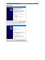
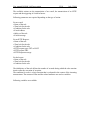
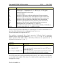
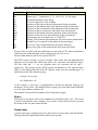
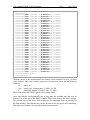
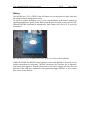
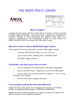
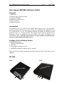
User manual BS1000 LAN base station
1/18
July 5 2010
User manual BS1000 LAN base station
Contents
1.Introduction
2.Package of the LAN Base Station
3.Software installation
4.Installation of the Receiver
5.Sensor operation
6.Software operation
Introduction
The BS1000 is a receiver station for the AREXX Multi Logger system. Like the BS500
station, the BS1000 receives sensor data via wireless transmission and sends these data
via a USB interface to a PC. The additional Ethernet link enables the BS1000 to send
measured values via a TCP/IP protocol. This interface allows also the transmission of
Messenger e-mails. In addition to that, the built-in web server can display recent
measurement values. With the latest software it is also possible to synchronize the
data of several BS-1000 or BS-500 receivers.
Package of the LAN Base Station
Contents of the package:
1. LAN Base Station module
2. USB cable
3. Power supply net adapter 5V DC.
4. CD-ROM including the software and user manual
Please check if the package contains all parts and contact your dealer if the package is not
complete.
BS-1000
Front
Back
1
5
2,3,4
6
7
User manual BS1000 LAN base station
1. On/Off switch
2. Red LED
3. Blue LED
4. Green LED
2/18
July 5 2010
5 LAN connector
6. USB connector
7. DC connector
LED functions:
Red LED
Blue LED
Green LED
–
–
–
–
LED is on when the BS-1000 is powered on.
Blinks when the BS-1000 receives sensor data
Off: network and flash memory storage are not active
On: network not active, flash storage active,
Blinks short on and long off: network active, no flash storage
Blinks long on and short off: network active, flash storage active
Software Installation
Prior to using the BS1000 via USB, you have to install the supplied software on your PC.
Insert the supplied CD-ROM into the CD drive of your PC. After insertion the
installation wizard will appear. If the automatic set up has been disabled in your
Windows software, you can activate the window by opening the Explorer file, go to the
CD drive and double-click on the default.htm file.
Select your language on the installation screen and then select the installation option.
Follow the instructions on the screen.
Installation of the receiver
Once you have installed the software and connected the BS1000 to the 5V power supply,
you can connect the receiver module (BS1000) to your computer via the supplied USB
lead. Windows will now start installing the required RF_USB driver. Depending on your
Windows version, the installation process may slightly vary:
User manual BS1000 LAN base station
Windows XP:
Please select ‘No, not this time’ and click on ‘Next’.
Choose the automatic software installation and click on ‘Next’
3/18
July 5 2010
User manual BS1000 LAN base station
4/18
July 5 2010
A Windows-Logo test has not been requested for the RF_USB-driver.
Therefore click on: ‘Continue Anyway’.
When the installation is complete, click on ‘Finish’.
Once the driver has been installed, you can start the application.
You can start the program via the start menu: Start->All Programs->Temperature-Logger.
On the left side a (still empty) sensor list is displayed. On the right side is a space for a
graphic display of the measured temperature curves. On the left bottom side of the screen
a status bar displays the message 'Ready'.
User manual BS1000 LAN base station
5/18
July 5 2010
Software operation
The temperature data will be received and stored as soon as the Windows system has
been started. Therefore it is not necessary to start the temperature-logger program to store
new data.
The program offers following functions:
•Graphic display of the measured temperatures for every individual sensor
•Settings for every individual sensor
•Export data in various formats
For further details please refer to the on-line help for the program.
In addition to that, the CD contains two extra tools: the NetworkConfig program to help
you detect the network parameters that the BS1000 is using, and the RuleEditor which is
a tool to build the messenger-control file that you need to control the built-in Messenger
facility. Furthermore, the BS1000 web server offers some administrative pages for
various settings.
NetworkConfig
The NetworkConfig-tool requests the network parameters of a BS1000 connected via
USB. To this end, the temperature-logger software should be installed already. These
network parameters allow you to look directly at the BS1000 web server. The standard
settings of the BS1000 sets the network name to 'log' followed by two digits. This name
is depicted on the BS1000 housing. With this name you can browse directly to the
webserver of the BS1000. The networkconfig tool is used to read or change its network
settings directly, if first connection is not possible.
In addition to the data logger, the web server contains administrative pages in which you
can set the parameters of the various functions:
- Network parameter
- E-mail parameter
- Messenger parameter
- Sensor parameter
- Internet time parameter
- Password
- Event Log parameter
In conjunction to the temperature logger software, the network config program displays
following window:
User manual BS1000 LAN base station
6/18
July 5 2010
The window contains the following fields:
- Use DHCP: If this box is checked, the BS1000 will use the network settings of an
available DHCP server. In this case, the other fields below remain inactive. If this box is
not checked, the network settings are static and the other fields must be filled in.
- Address: the current IP address of the BS1000
- NetMask: the utilized net mask setting
- Gateway: the utilized Gateway-address
- DNS server: the current DNS server
- Network name: the network name of the BS1000
- DNS suffix: the network suffix as indicated by the BS1000.
The Read button asks the BS1000 to supply the parameters.
The Write button writes the parameters into the BS1000.
The BS1000 web server is located at the address defined by the network name, followed
by the DNS network addition. In the example shown above the BS1000 is located at the
address: http://log40.lan.
The standard network name is 'log', followed by 2 digits. This name is indicated on the
housing of the BS1000.
This method allows you to browse directly to the indicated address without any tools.
User manual BS1000 LAN base station
7/18
July 5 2010
BS1000 Web server
The built-in web server contains a few pages of the most recent measurements. Moreover
the program offers administrative pages for various settings.
The BS1000 web server is located at the address that has been defined by the network
name, followed by the DNS network addition. Please note that an eventual blocking by a
firewall and/or browser should be disabled as long as these apply to the BS1000.
For every single sensor, the Initial page shows the most recent measurements:
In this case, the latest measurement received per sensor is registered. The time indication
is formatted according to the standard setting of the computer. The rssi column displays
the radio strength of the signal received.
You can access the admin pages via the link called 'Admin' on top of the screen.
After entering the User ID and the password (the standard settings are admin/admin) the
program activates following window:
User manual BS1000 LAN base station
8/18
July 5 2010
The active Firmware version is displayed on the screen. Further down we will explain the
links in the left column:
Network
This window contains the same data that have already been explained in the
NetworkConfig tool. You might update the settings via the Submit button, if necessary.
User manual BS1000 LAN base station
9/18
July 5 2010
E-mail
This page determines the data of the e-mail server address that is used to send the
Messenger records to an e-mail address.
The 'From field' defines the e-mail address of the sender that is used for the transmission
of the Messenger e-mail. In some cases, the user name and the password must be entered.
This can be done in the two lower fields. However, in most cases the user name and the
password are not required.
Sensors
The values of the incoming measurements are converted according to the sensor
definition file. This definition file is an xml file that contains the required parameters for
the conversion. If new sensor types are added, the relevant definition file can be uploaded
here so that the BS1000 can use these indications for the operation. When you submit an
empty file field, the default internal definition file is used.
User manual BS1000 LAN base station
10/18
July 5 2010
Messenger
The Messenger is configured via a 'Rule file' that is set up via a so-called ,Rule Editor'
and which contains one or more Messenger rules. These indications define actions that
are triggered as soon as one or more conditions are met. The currently valid 'Rule file'
will be marked as „current version“. Further details are given in the description of the
Rule Editor. When you submit an empty file field, the current rule file is erased, and no
rules are applied.
Names
Instead of showing sensors by id, sensors can be shown by their names. An xml file with
a namelist can be uploaded on this page. The namelist file is created by a small tool from
the temperature logger software (Name list editor). Besides manual entry of names, a list
can be imported by the tool from the temperature logger software.
User manual BS1000 LAN base station
11/18
July 5 2010
Time server
At the start up of the BS1000 and in certain time intervals (provided that the system has
been configured accordingly), the time is requested from an Internet time server and the
internal clock of the base system is updated by this time.
The clock of the BS1000 system is powered by a button cell when the station is switched
off. Therefore the BS1000 system will always register new measurement data after
switching on. This applies also for operation without PC nor network link.
The Messenger function is based on the availability of the internal clock. This clock uses
the standard time (UTC). The adjustment of the time zone is entered in minutes into the
field „Time Zone Offset“. The time indicated on the web pages of the BS1000 is local
time and based on the time parameters of the PC in charge of the browser.
Password
The admin pages of the BS1000 can only be accessed via a password. The standard
password is 'admin' and can be changed on this page.
User manual BS1000 LAN base station
12/18
July 5 2010
Recent Events
The Recent Events screen shows a short summary of the most recent events that the
BS1000 has recorded. The results of the executed rule actions are indicated in lines per
sensor. In addition to the executed rule actions, other events such as access to web pages
and DHCP actions are recorded.
Rule Editor
The Rule-Editor is a tool for the creation of a “rule” file that is used by the BS1000 to
control the built-in Messenger functions. The Messenger function allows the start of one
or more actions based on an incoming measured value, if its associated condition is met.
User manual BS1000 LAN base station
13/18
July 5 2010
The available actions are the transmission of an e-mail, the transmission of an HTTP
request and the triggering of a built-in buzzer.
Following parameters are required depending on the type of action:
For an e-mail:
• Name of the rule
• Time lock for the rule
• Condition for the rule
• E-mail address
• Subject of the rule
• E-mail message
For an HTTP Request:
• Name of the rule
• Time lock for the rule
• Condition for the rule
• HTTP request type: GET or POST
• HTTP request URL
• HTTP Request message
For the buzzer:
• Name of the rule
• Time lock for the rule
• Condition for the rule
The inhibit time of the rule defines the number of seconds during which the rules remains
inactive after the execution of an action.
The condition for a rule is a logic function that is evaluated in the context of the incoming
measurement. The measured value and the related attributes are used as variables.
Following variables are available:
User manual BS1000 LAN base station
Variable
$v
$q
$i
$r
$h
$m
$s
$Y
$M
$D
$S
$c
$a(len)
14/18
July 5 2010
Description
Measured value
Sensor type 1 = Temperature (°C), 3 = RV% (%), 5=CO2 (ppm)
Identification number of the sensor
rssi-value (dBm)
Indication of the hours in the time indication of the measurement
Indication of the minutes in the time indication of the measurement
Indication of the seconds in the time indication of the measurement
Indication of the year in the time indication of the measurement
Indication of the month in the time indication of the measurement
Indication of the day in the time indication of the measurement
Measurement time in seconds since 1-1-2000 UTC
Day of the week at the time of measurement (0=Sunday, 1=Monday...)
Current average value (len = Length in seconds)
Except for the $S, all time indications are expressed in UTC under consideration of the
time zone offset indication in the config page screen Time server.
The time indication $S is expressed in UTC.
The condition is structured like a logic expression. Following logical comparison
operators can be used for the definition: (<, <=, >, >=, <>, == en !=), as well as the
logical operators AND (&&), OR(||) and NOT(!). Moreover the expression can be
organised via the brackets „(„ and „)“.
Examples:
Expression
$v<10
$v<10 && $i=8297
($v<-10 || $v>10)&&c==0
Description
is true as soon as the measurement goes below the value
10 .
is true as soon as the measurement for sensor 8297 goes
below the value 10.
is true as soon as the measurement goes below the value
-10 or above10 and the day of the week is a Sunday.
The HTTP-report, the e-mail report and the subject line for the e-mail are text fields that
can be fitted with variables. The value of a variable will be replaced by text when the
message text is set up.
The list of variables is:
User manual BS1000 LAN base station
Variable
$v
$q
$i
$r
$h
$m
$s
$Y
$M
$D
$S
$w
$t
$d
15/18
July 5 2010
Description
Measured value
Sensor type 1 = Temperature (°C), 3 = RV% (%), 5=CO2 (ppm)
Identification number of the sensor
rssi-value (signal level value in dBm)
Indication of the hours in the time indication of the measurement
Indication of the minutes in the time indication of the measurement
Indication of the seconds in the time indication of the measurement
Indication of the year in the time indication of the measurement
Indication of the month in the time indication of the measurement
Indication of the day in the time indication of the measurement
Measurement time in seconds since 1-1-2000 UTC
Missing; Time when the latest measured value has not been transmitted to
the http server. Is required for the update of the temp-logger.
time string; Time of measurement in the format: hh:mm:ss
datum string; Date of the measurement in the short date format
Except for the $w and $S, all time indications are expressed in UTC under consideration
of the time zone offset indication in the config page screen Time server.
The time indications $w and $S are expressed in UTC.
The HTTP request message is base64 encoded. This means that non-alphanumerical
characters are converted into %hh-strings where „hh“ represents a hexadecimal figure.
The lines '&&' and '==' are an exception: these are converted into '&', and '='
respectively. The message for the HTTP request is transmitted via the request header
POST, or else added to the URL of the GET request. In this case, the separating sign '?' is
added between the URL and the message.
Example of a message:
id==$i&&value==$v
In this example, a web server is programmed to decode the indicated string in two
parameters 'id' and 'value'. This method allows to supply up-to-date data from the BS1000
to a web page without a running a PC.
This method is also used for the update of the Temperature Logger.
Buzzer
The buzzer is activated as soon as the condition has reached the value “true”. The buzzer
is shut off automatically after 5 minutes. You can also switch off the buzzer by pressing
the button on the rear panel of the BS1000.
Flashed data
A special xml page is implemented to let other software retrieve data from the BS1000.
The page data.xml outputs flashed data within a given period.
User manual BS1000 LAN base station
16/18
July 5 2010
The page is called with 4 parameters:
Parameter Type
name
Description
A
timestamp
Start of period; number of seconds since 1-1-2000
B
timestamp
End of period; number of seconds since 1-1-2000
C
integer
Sensor id
D
integer
Sensor type; 1=temperature, 3= RH%, 5=CO2
Example:
http://log77.lan/data.xml?A=327682224&B=327685203&C=4096&D=1
This call would result in the following dataset:
User manual BS1000 LAN base station
17/18
July 5 2010
<?xml version="1.0" encoding="utf-8" ?>
<measurements>
<value id="4096" type="1" t="327682224">25.1</value>
<value id="4096" type="1" t="327682287">39.5</value>
<value id="4096" type="1" t="327682335">33.7</value>
<value id="4096" type="1" t="327682378">30.7</value>
<value id="4096" type="1" t="327682417">28.9</value>
<value id="4096" type="1" t="327682493">26.8</value>
<value id="4096" type="1" t="327682581">25.4</value>
<value id="4096" type="1" t="327682660">24.7</value>
<value id="4096" type="1" t="327682718">24.4</value>
<value id="4096" type="1" t="327682783">24.1</value>
<value id="4096" type="1" t="327682833">23.9</value>
<value id="4096" type="1" t="327682877">23.8</value>
<value id="4096" type="1" t="327682949">23.6</value>
<value id="4096" type="1" t="327683003">23.5</value>
<value id="4096" type="1" t="327683048">23.5</value>
<value id="4096" type="1" t="327683119">23.4</value>
<value id="4096" type="1" t="327683172">23.3</value>
<value id="4096" type="1" t="327683217">23.3</value>
<value id="4096" type="1" t="327683257">23.2</value>
<value id="4096" type="1" t="327683295">23.2</value>
<value id="4096" type="1" t="327683332">23.2</value>
<value id="4096" type="1" t="327683408">23.2</value>
<value id="4096" type="1" t="327683463">23.2</value>
<value id="4096" type="1" t="327683533">23.1</value>
<value id="4096" type="1" t="327683624">23.1</value>
<value id="4096" type="1" t="327683687">23.1</value>
<value id="4096" type="1" t="327683736">23.1</value>
<value id="4096" type="1" t="327683778">23.1</value>
<value id="4096" type="1" t="327683855">23.1</value>
<value id="4096" type="1" t="327683942">23.1</value>
<value id="4096" type="1" t="327684021">23.0</value>
<value id="4096" type="1" t="327684078">23.0</value>
<value id="4096" type="1" t="327684124">23.0</value>
<value id="4096" type="1" t="327684165">23.1</value>
<more>327684165</more>
</measurements>
The data consists of the 'measurements' root element, which contains a list of 0, 1 or more
value elements. Each value element represent a measurement, and it has the following
attributes:
• id
sensor id
• type sensor type; 1=temperature, 3= RH%, 5=CO2
• t
timestamp; number of seconds since 1-1-2000
The measurement value itself is given as the element value.
Since data transfer could potentially take a long time, the resulting xml data may be
truncated, as is the case in the above example. This is indicated by the 'more' element.
The element value of the 'more' element gives the last timestamp that was examined in
the flash memory. Note that this may not be the same as the last given value timestamp.
When the more element is not present, the data is not truncated.
User manual BS1000 LAN base station
18/18
July 5 2010
Battery
The BS1000 has a 3V Li CR2032 coin cell battery for powering the real time clock and
the settings memory during power down.
We advise to replace the battery every 3 years. Actual lifetime of the battery depends on
operating temperature, quality of the battery and the period of time it stays powered off.
When the BS1000 is powered on continuously, then a battery life of over 10-15 years can
be expected.
The coin battery cell is located at the centre of the circuit board of the BS1000.
Unlike the BS500, the BS1000 starts logging as soon as the BS1000 is powered on. No
further requirements are necessary. The only exception is the first time use or when the
coin battery was removed: Then the clock must be set, before logging can start. This can
be done via the USB port, connected to the temperature logger software, or by a remote
time server via the network.