1
DOEPFER
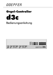
Organ Controller
d3c
User's Guide
Operating and Safety Instructions
Please follow the given instructions for use of the instrument because this will guarantee
correct instrument operation. Due to the fact that these instructions touch on Product
Liability, it is absolutely imperative that they be read carefully. Any claim for defect will be
rejected if one or more of the items was observed. Disregard of the instructions can
endanger warranty.
•
•
•
•
•
•
•
•
•
•
•
•
•
•
The instrument may only be used for the purpose described in this operating manual.
Due to safety reasons, the instrument must never be used for other purposes not
described in this manual. If you are not sure about the intended purpose of the
instrument please contact an expert.
The instrument has to be shipped only in the original packaging. Any instruments shipped
to us for return, exchange, warranty repair, update or examination must be in their
original packaging! Any other deliveries will be rejected. Therefore, you should keep the
original packaging and the technical documentation.
The instrument may only be operated with the voltage written on the power input on the
rear panel. Before opening the case disconnect the power plug.
Every modification has to be carried out only at the manufacturer or an authorized
service company. Any modification not released by the manufacturer leads to the
extinction of the operation permission.
With the introduction of a third person the warranty will be lost. In case of a destroyed
warranty seal, any warranty claim will be rejected.
The instrument must never be operated outdoors but only in dry, closed rooms. Never
use the instrument in a humid or wet environment nor near inflammables.
No liquids or conducting materials must get into the instrument. If this should happen the
instrument must be disconnected from power immediately and be examined, cleaned and
eventually be repaired by a qualified person.
Never subject the instrument to temperatures above +50°C or below -10°C. Before
operation the instrument should have a temperature of at least 10°C. Do not place the
instrument into direct sun light. Do not install the instrument near heat sources.
Keep the top side of the instrument free in order to guarantee proper ventilation,
otherwise the instrument could be overheated. Never place heavy objects on the
instrument.
All cables connected with the instrument must be checked periodically. If there is any
damage the cables must be repaired or replaced by an authorized person.
Transport the instrument carefully, never let it fall or overturn. Make sure that during
transport and in use the instrument has a proper stand and does not fall, slip or turn over
because persons could be injured.
Never use the instrument in the immediate proximity of interfering electronic devices (e.g.
monitors, computers) since this could create disturbances within the instrument and
corrupt memory data.
The exchange of electronic parts (e.g. EPROMs for software update) is allowed only if
the instrument is disconnected from power supply.
When using the instrument in Germany, the appropriate VDE standards must be
followed. The following standards are of special importance: DIN VDE 0100 (Teil
300/11.85, Teil 410/11.83, Teil 481/10.87), DIN VDE 0532 (Teil 1/03.82), DIN VDE 0550
(Teil 1/12.69), DIN VDE 0551 (05.72), DIN VDE 0551e (06.75), DIN VDE 0700 (Teil
1/02.81, Teil 207/10.82), DIN VDE 0711 (Teil 500/10.89), DIN VDE 0860 (05.89), DIN
VDE 0869 (01.85). VDE papers can be obtained from the VDE-Verlag GmbH, Berlin.
d3c
Page 2
User's Guide V1.0
Servicing / Updates
There are no controls, adjustments or other elements inside the case that have to be
operated by the user.
In case of an firmware update the case has to be opened to replace the main processor by
the new version. This service has to be carried out normally by the representative or dealer
where the device has been purchased. The service is offered by the manufacturer (Doepfer,
Germany) or an authorized dealer or service company too. Please look at the web site
www.doepfer.com for a list of all authorized companies.
Any firmware update is not free of charge. The costs for material, working time and shipment
is charged to the customer.
You may even carry out firmware updates yourself at your own risk. In this case the warranty
is lost if a mistake is made during the firmware update.
Pay attention that cases that are damaged while the device has been opened/closed (e.g.
scratched surface, damaged screws) cannot be taken back and the warranty is void.
The device d3c uses a rechargeable battery (accumulator) for memory backup of preset
data. These electronic parts have a limited lifespan and have to be inspected at least every
two years. This should be carried out by qualified personnel only as technical knowledge and
soldering experience is necessary. If you are able to carry out the inspection and the
possible replacement yourself this is the checking/replacement procedure:
•
•
•
•
•
•
•
•
Disconnect the device completely from mains voltage (i.e. remove the mains cable,
turning the device off with a mains switch is not sufficient !)
Open the case and find out the position of the battery (this is a black or blue cylindric
electronic part with about 15 mm diameter and 15 mm length, the target voltage "3.6V" is
printed on the part).
Optical inspection: check if the battery is still sealed and has no leakage.
Electrical inspection: measure the battery voltage with a suitable instrument (e.g. digital
multimeter in voltage mode). The voltage has to be within 10% of the target voltage
(3.6V), i.e. between ~ 3.2V and ~ 3.9V.
If the optical or electrical inspection indicates any fault the battery has to be replaced by
the same type (i.e. 3.6V rechargeable battery / accumulator with the same dimension).
Suitable batteries are available in electronic stores or from your local Doepfer
representative as spare part.
If the battery is defective the old one has to be removed (desoldered) and the new one
put in (soldered).
muss der Akkumulator ausgewechselt werden. Der Akkumulator ist im ElektronikFachhandel erhältlich oder kann von uns oder einer unserer Vertretungen als Ersatzteil
bezogen werden.
It is not allowed to put the old battery to the normal garbage. Please forward the old
battery for recycling to a suitable receiving office.
Technical data are subject to change without notice.
The topical version of this guide is available for download as pdf file on our website
www.doepfer.com (MANUALS section).
© 2006 by
Doepfer Musikelektronik GmbH
Geigerstr. 13
82166 Gräfelfing
Phone: +49 89 89809510
Fax: +49 89 89809511
www.doepfer.com
d3c
Page 3
User's Guide V1.0
Contents
Operating and Safety Instructions................................................................................2
Servicing / Updates ......................................................................................................3
Introduction ..................................................................................................................5
Connections (rear panel)..............................................................................................6
Power Supply n o ................................................................................................6
USB p .....................................................................................................................7
Midi In q / Midi Out r ...........................................................................................7
FOOT CONTROL ] /
^......................................................................................9
FOOT SWITCH _ ...................................................................................................9
Operation ...................................................................................................................10
Operation Modes ....................................................................................................12
B4 Mode ..............................................................................................................12
Other Modes........................................................................................................13
Appendix ....................................................................................................................14
Firmware updates ...................................................................................................14
Troubleshooting ......................................................................................................14
d3c
Page 4
User's Guide V1.0
Introduction
d3c is part of the modular organ masterkeyboard system d3 that is intended as a control
unit for organ emulations like Native Instruments B4 or Emagic evb3. The system has two
modules available: the keyboard unit d3m and the drawbar control unit d3c. Each of the
modules can be used alone or in combination with the other modules. The maximum system
consists of two keyboards d3m and one control unit d3c (and one bass pedal d3b as soon as
it is available). The bass pedal d3b is in preparation as the third module of the system.
The second part of the modular concept is drawbar control unit d3c: This unit contains all
elements required to control a typical organ emulation: 9 drawbars for upper manual, 9
drawbars for lower manual, 2 drawbars for bass pedal, 6 rotary controls for the parameters of
tube and percussion and a lot of additional buttons for vibrato, chorus, key click, rotary
speakers and so on. Even the 10 + 12 program selection buttons of the keyboard unit d3m
are available. This is necessary if the (one or two) d3m are mounted with hidden button
sections.
The connection between the d3 modules is established via Midi. The control unit d3c is
equipped with both Midi and USB interface. This allows to connect the d3 combination to
both worlds Midi and USB (e.g. a laptop that runs B4 or evb3).
The control unit d3c can be used as a stand-alone device or in combination with one
or two of the d3m keyboards (or even with other Midi keyboards). The mechanical
connection between the units is made with mounting angles or wooden side plates
that are available as accessories. Details about the available accessories and the
different mounting versions of d3m and dc3 can be found on our website
www.doepfer.com.
d3c
Page 5
User's Guide V1.0
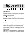
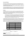
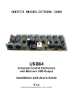
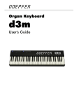
Connections (rear panel)
n
Power Supply n
o
p
q
r
]
^
_
o
d3c does not have a built-in power supply. Instead it uses a plug-in type external power
supply (AC adapter). One reason for this feature is electrical safety. Keeping danger voltages
(mains) out of the d3c increases the electrical safety. Another reason for the external power
supply is the fact that line voltages and plug types vary considerably from country to country.
Using a plug-in external supply the d3c can be used anywhere with a locally purchased
power supply, thus keeping the retail price down.
XLR socket
n
(labelled 9V DC In) is the power supply input socket. A power supply with
XLR plug is connected into this socket. Socket o (labelled 9V DC Out) is used to pass on
the supply voltage to the d3m unit(s) provided that one or two d3m are used in combination
with the d3c. Consequently only one power supply is necessary for the complete system
(d3c+d3m or d3c+2xd3m).
Internally the sockets n and o are connected. If only a d3c is used without d3m even
socket o can be used to supply the d3c. In this case sockets n remains unused.
Special cables with a low voltage DC plug on each side are used to connect d3c → d3m or
d3m → d3m. If the d3c is ordered together with one or two d3m suitable cables are
enclosed. Otherwise they have to be ordered later.
In Europe a VDE approved power supply (9V/800mA) is included with the d3c. This supply is
sufficient for up to one d3c and two d3m (see below). In other countries a power supply with
suitable mains voltage and mains connector has to be purchased separately by the user
provided that the dealer resp. representative does not enclose the power suppy. The power
supply must be able to deliver 7-12 VDC stabilized or unstabilized voltage, as well as a
minimum current of 250mA (if only the d3c is used). The correct polarity of the DC voltage
connector is: outside ring = GND, inside lead = +7...12V. An external power supply of high
quality and safety should be used. If one or two d3m have to be supplied with the same
power supply additional 250 mA are required for each d3m (i.e. 500mA for d3c + d3m,
750mA for d3c + 2x d3m).
The d3c is switched on by plugging the AC adapter into a wall outlet and connecting it to the
appropriate jack of the d3c. There is no separate on/off switch. If the polarity of the power
supply is incorrect, the d3c will not function. However, there is no danger of damage to the
circuitry since it is protected by a diode.
d3c
Page 6
User's Guide V1.0
USB p
This is the USB connector of d3c. If you want to run the d3c via the USB interface (instead of
Midi) this socket has to be connected to the USB socket of your computer with a suitable
cable (A-B type). A suitable cable is included with the d3c. But each standard A-B type USD
cable will work. The computer system has to be equipped with so-called generic USB
device class drivers for Midi devices. These are included in the Windows XP™ or Mac
OSX™ operating system.
Former Windows™ or Mac™ operating systems are not supported. In these cases the Midi
interface of d3c has to be used.
If the operating system supports the USB device class drivers the computer recognizes the
d3c connection as soon as the USB cable is connected and the corresponding driver is
installed. This is normally indicated by an acoustic computer signal.
After that a new Midi Input and Output labelled USB audio device is available and can be
used in all programs (e.g. Native Instruments B4).
If an error message appears (e.g. "USB device not recognized" or similar) the required USB
driver is probably not available or not installed on the computer. It is difficult to find out the
reason why it does not work as it depends upon the hardware and software (especially the
operating system and the installed drivers) of the computer.
But we will try to give some hints in this manual and on our website provided that we hear
about such problems and their solutions.
Using the USB connection has both advantages and disadvantages compared to the Midi
connection. Please read the corresponding notes in this manual and on our website.
Midi In q / Midi Out r
This is the Midi output and the Midi Input of d3c. There are different possibilities how to use
these sockets:
•
Only the d3c is used (no d3m or other Midi keyboards):
In this case Midi Out of d3c is connected to Midi In of the sound generator that is
controlled by d3c (e.g. computer with organ emulation, stand-alone organ exander). The
Midi In of the d3c remains unconnected in this case.
A typical example for this type of connection is a running sequence (e.g. with the VST
plugin B4) that is modified while it's running.
•
The d3c is used in combination with one or more d3m (or other Midi keyboards):
The d3m and d3c are daisy chained via Midi In and Out. Midi Out of the first d3m is
connected to Midi In of the second d3m. Midi Out of the second d3m is connected to
Midi In of the d3c. Midi Out of d3c is connected to Midi In of the sound generator that is
controlled by the d3c/d3m (e.g. computer with organ emulation, stand-alone organ
exander). Each d3m requires a different Midi channel to be able to distinguish the
keyboards (for details please refer to the d3m manual).
If a bass pedal d3b is used (future module) the Midi Out of the d3b is connected to Midi
In of the first d3m in the chain.
If Native Instruments B4 is used the Midi channels of the d3m keyboards have to be set
d3c
Page 7
User's Guide V1.0
in this way:
lower manual: Midi channel 2
upper manual: Midi channel 1
The Midi In of the first d3m in this chain remains unconnected or it is connected to the
Midi Out of the computer that runs the organ emulation (e.g. B4). This connection is only
necessary if a Midi feedback is needed.
Attention: This type of connection contains the risk of a Midi feedback loop ! The Midi
data sent by the computer are passed on in the d3m/d3c chain and consequently appear
again at the Midi In of the computer. One has to pay attention that the software in use
does not pass on the incoming Midi data again to it's output (no Midi "echo" from Midi In
to Midi Out) as this would cause an Midi "avalanche" and probably lead to a crash or
freezing of the computer system.
If the connection is made and the settings of the software are correct (i.e. no Midi "echo")
the new settings after a preset change are displayed with the LEDs of the d3c provided
that the software in use outputs this information via Midi Out. This guarantees a perfect
tuning of hard and software.
For optimal function of the display feedback the update V1.1.5 of Native Instruments B4
is required. This is available only for Mac OS X and Win XP but not for Mac OS 9 !
d3c will work perfect with each version of B4 (Mac OS 9, OS X, Win), but the Mac OS 9
version does not support the feedback function for the LED display of d3c!
If the computer in use has several Midi inputs/outputs available we recommend to
connect the Midi Out of each d3m and d3c to a separate Midi input (rather than daisy
chaining the devices via Midi In/Out) and to connect one Midi Out of the computer to Midi
In of the d3c - paying attention to the remarks mentioned above concerning the Midi loop
problems.
Remark: The Midi input of d3c should be used only for connection to a d3m or d3b module
or another Midi keyboard or bass pedal that transmits only Midi note on/off messages ! The
Midi input is not suitable for large amounts of Midi data (e.g. SysEx strings or Midi messages
coming from a computer sequencer) but only for small data rates like the messages of a
d3m or d3b module. In case of large amounts of incoming Midi messages data loss or delay
may occur.
d3c
Page 8
User's Guide V1.0
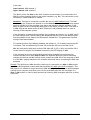
FOOT CONTROL ] /
^
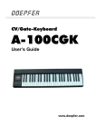
These stereo jack sockets can be used to connect two foot controllers. Do not connect the
foot controller unless the d3c is switched off. The foot controller functions are fixed to these
paremeters:
Foot Control 1 (^):
Foot Control 2 (]):
Loudness
Expression
We recommend the usage of the foot controllers FP5. Foot controllers are not included with
the d3c and have to be ordered separately if required. You may use even other foot
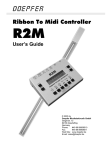
controllers that are connected in this way:
high
end
low
end
Foot control connection
10-100k linear
If you do not want to use a foot controller the socket remains unconnected.
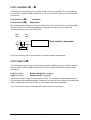
FOOT SWITCH _
This stereophonic jack socket can be used to connect a double foot switch. Do not connect
the foot switch unless the d3c is switched off. The foot switch functions are fixed to these
paremeters:
Left foot switch:
right foot switch:
Rotator Slow/Fast (toggling)
Rotator On/Off (toggling)
We recommend the usage of the foot switch VFP2. The foot switch is not included with the
d3c and has to be ordered separately if required. You may use even another foot switch that
uses contacts that are closed at rest (i.e. the contacts open when operated).
If you do not want to use a foot switch the socket remains unconnected.
d3c
Page 9
User's Guide V1.0
Operation
The d3c is switched on by plugging the AC adapter into a wall outlet and connecting it to the
appropriate jack of the d3c. There is no separate on/off switch.
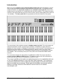
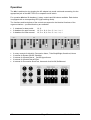
For operation d3c has 20 drawbars, 6 rotary controls and 38 buttons available. Each button
is equipped with a corresponding LED (light emitting diode).
The functions and inscriptions of the controls correspond to the identical functions of the
organ emulations – provided that they are available:
•
•
•
2 drawbars for bass pedal :
9 drawbars for upper manual:
9 drawbars for lower manual:
•
•
•
•
•
6 rotary controls for Keyclick, Percussion Harm., Tube Body/Bright,Overdrive,Volume
2 buttons for Rotator On/Off, Slow/fast
2 buttons for Vibrato/Chorus, On/Off Upper/Lower
6 buttons for Vibrato/Chorus Effect
4 buttons for Percussion Slow/Fast, Harmonic click,On/Off,Soft/Normal
d3c
16, 8
16, 5 1/4, 8, 4, 2 2/3, 2, 1 3/5, 1 1/3, 1
16, 5 1/4, 8, 4, 2 2/3, 2, 1 3/5, 1 1/3, 1
Page 10
User's Guide V1.0
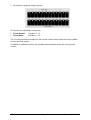
•
24 buttons for program change (preset).
The buttons are organized in two groups:
•
•
Preset Number:
Preset Bank:
12 buttons 1...12
10 buttons 1...10
The 12 number buttons correspond to the reverse colored lowest octave that was available
in some previous organs.
In addition up and down buttons are available that increase/decrease the current preset
number.
d3c
Page 11
User's Guide V1.0
Operation Modes
After power on all LEDs turn on and go out from left to right. Then all LEDs light up for a
short time and go out. After that the current software version is indicated for a short time by
using the Bank and Number LEDs. The Bank LED shows the main software version, the
Number LED the sub-version (e.g. Bank LED #1 only indicates software V1.0, Bank LED #2
and Number LED #4 on indicate V2.4).
Then the normal operation mode is called up. As long as no preset has been defined (either
by pressing the Bank/Number buttons or by receiving a Midi program change message via
Midi) the LEDs of Bank #1 and Number #1 are flashing. This in the signal that so far no
preset has been selected and consequently the states of all parameters are still undefined.
B4 Mode
This mode is intended for the combination of d3c with the organ emulation B4 of Native
Instruments and is up to now the only available mode. Because of the more versatile
functions – compared to the EVB3 and Remote mode – the B4 mode can be used for other
applications too, e.g. to control any Midi sound module via the note and progam change
messages that are available in B4 mode.
Pay attention that most manufacturers count the Midi program change numbers from
0....127 others from 1...128. In this manual we use the range 0...127 as this is more
common. If the device connected to the Midi output of d3m does not respond as
expected the different counting ranges may be the reason. In this case you simply
have to add "1" to the program change number stated in this manual. Same applies
for Midi channels too (i.e. counting from 0 to 15 resp. 1 to 16).
In the B4 mode the 22 buttons are used to transmit Midi Program Change Messages. The
number buttons generate the program numbers 0...11 (resp. 1...12 in the 1...128 counting
system). The bank buttons are used to add a fixed value ("offset") to the program number
generated by the number buttons. The offset value generated by the bank buttons is a
multiple of 12. The offset is 0 for bank #1, 12 for bank #2, 24 for bank #3 and so on. The
table below shows an overview of the available program change numbers for each bank:
Bank
1
2
3
4
5
6
7
8
9
10
Program number range for counting system
0 – 127
1 – 128
0 – 11
1 – 12
12 – 23
13 – 24
24 – 35
25 – 36
36 – 47
37 – 48
48 – 59
49 – 60
60 – 71
61 – 72
72 – 83
73 – 84
84 – 95
85 – 96
96 – 107
97 – 108
108 – 119
109 – 120
The corresponding formula for the resulting program change number generated by the
number and bank buttons is this:
Number – 1 + 12 x (Bank – 1)
Example: Number = 5, Bank = 3
The resulting programm number is 5 – 1 + 12 x (3 –1) = 4 + 24 = 28.
d3c
Page 12
User's Guide V1.0
The last available program change number is 119 (number #12 in bank #10). The program
change numbers 120...127 are not available. In practice the Midi program number generated
by the number and bank buttons is of minor importance as one will remind the number and
bank buttons used for a certain sound but not the program change number that is assigned
to this sound.
The assignment of Midi control change numbers to d3c controls (drawbars, buttons)
matches with the B3 software. For details please refer to the B4 user's manual.
Other Modes
Other operation modes are in the planning state (e.g. Evb3). They can be downloaded via
firmware updates to the d3c as soon as they are available. For details please look at our
website www.doepfer.com.
d3c
Page 13
User's Guide V1.0
Appendix
Firmware updates
The latest version of the user's manual and the topic version of the d3c firmware are
available on our website www.doepfer.com in the sections MANUALS or DOWNLOAD.
Troubleshooting
Symptom:
The B4 software does not follow to the parameter changes of the d3c and does not respond
to preset changes triggered by the d3c (Bank/Number buttons). If one or two d3m keyboards
are used the B4 does not respond when keys on the d3m are pressed down.
Solution/explanation/reason:
Midi Out of the d3c has to be connected to Midi In of the computer.
The Midi Output interface of the B4 has to be routed to the right port and to be turned on.
Symptom:
No feedback to the d3c when a parameter or preset change is triggered in the B4 software
Solution/explanation/reason:
Check the Midi connections: For this even Midi Out of the computer has to be connected to
Midi In of d3c (directly or daisy-chained via one or two d3m).
The Midi Output interface of the B4 has to be routed to the right port and to be turned on.
For the complete dump during a preset change in the preset menu of the B4 software the
function "B4D Controller Dump on Program Change" has to be active (available from version
1.1.5)
Symptom:
When the preset is changed in the B4 software the d3c parameters are updated (LED
settings change) but the correct preset number is not displayed (i.e. the settings of the
Bank/Number LEDs remain unchanged).
Solution/explanation/reason:
Unfortunately some versions of the B4 software do not transmit a program change message
when a new preset is called up. Consequently the d3c does not "know" the new preset
number as the corresponding information is not sent by the B4 software. The only solution is
to update the B4 software to a new version.
We ask for your understanding that we cannot give assistance to the correct installation of
the computer's operating system, the computer's Midi interface and the B4 software as these
things depend on the individual hardware and software components of each computer.
d3c
Page 14
User's Guide V1.0
Power on sequence / USB connection sequence
The USB connection between the computer and d3c must not be established or interrupted
while a program is running that uses the USB Midi port (e.g. B4) ! Otherwise the program can
block the connection or the Midi ports will not work any longer. In this case it is
recommended to reboot the computer.
If the USB connection has been already established earlier (or if the USB Midi port was
already in use) and the USB connection has been interrupted and established again it may
last several minutes until the USB Midi port is recognized again. In this case it is not allowed
to start a Midi program (e.g. B4) as otherwise the Midi port cannot be opened again. Even in
this case it is recommended to reboot the computer.
We have to point out that is not a problem of the d3c but of the operation system of the
computer and the USB drivers.
d3c
Page 15
User's Guide V1.0
Doepfer
Musikelektronik
www.doepfer.com
© 2006 by
Doepfer Musikelektronik GmbH
Geigerstr. 13
82166 Graefelfing
Germany
Phone: +49 89 89809510
Fax: +49 89 89809511
email: [email protected]
Web Site: www.doepfer.com