1
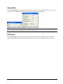
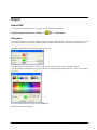
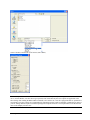
ARL
Expander
By ARL - Albacore Research Ltd.
COPYRIGHT © 2003 ALBACORE RESEARCH LTD.
Information in this ShipConstructor manual is the property of Albacore Research Ltd. No part of it can be reproduced,
translated, resold, rented, adapted, modified, stored in a retrieval system or transmitted in any form or by any means, in
whole or in part. All Rights Reserved. ShipConstructor is a trademark of Albacore Research Ltd.
SHIPCONSTRUCTOR LICENSE AGREEMENT
1.
License Grant. Albacore Research Ltd., #304 – 3960 Quadra Street, Victoria, B.C. Canada, V8X 4A3 (“ARL”) grants to the person accepting
this Agreement (the “Licensee”) a non-exclusive, non-transferable right to use (the “License”) in object code form those program modules
(“Software”) specified in the Licensee’s purchase order or request (“Order”) solely on the software and hardware listed in the Software manual
(“System Configuration”).
2.
Ownership. All rights, title and interests in and to the Software and related documentation shall remain the sole property of ARL. Licensee shall
not remove or alter any proprietary rights notices on the Software and the documentation, and shall reproduce such notices on any copies that it
makes. Licensee shall be liable for the security of the Software and the documentation in its possession.
3.
Expertise Required. Licensee is responsible for evaluating whether the Software meets Licensee’s requirements, and for operating the Software
and the results obtained. The Software is intended for ship modeling and construction purposes only, and must be used by a person who has
expertise and knowledge in this field. The Software requires independent confirmation of the reliability and accuracy of all designs, drawings
and other Software output.
4.
Restrictions on Software Use. Licensee shall not merge, translate or modify the Software, attempt to defeat any copy protection, make copies of
the Software or related documentation (except for object code copies required to run the Software on the System Configuration, and archive,
back-up and recovery copies), sub-license, sell, loan, rent, lease or otherwise transfer the Software to any person, or decompile, disassemble or
reverse engineer the Software.
5.
Term of License. The License term commences on the delivery of the Software to the Licensee, and is either perpetual if so requested on the
Order, or on a month to month basis that converts to a perpetual term (a) automatically after 12 months of payment of License fees, or (b) earlier
on Licensee’s payment of the balance of the perpetual License fee (prior monthly payments receiving 80% credit). All Licenses are subject to
termination in accordance with this Agreement.
6.
System Configuration. Operation of the Software requires use of the specified System Configuration, which Licensee shall acquire and
implement. ARL shall not be responsible for any operational problems caused by the System Configuration.
7.
Hardware Keys. Software use requires “Hardware Keys” supplied by ARL, which can be used only at the site(s) authorized by ARL. Upon
failure of its System Configuration, Licensee may upon advising ARL use the Hardware Keys and Software on another system and/or location.
8.
License Fees. Licensee shall pay to ARL the License fees applicable for the Software requested in the Order as either a perpetual License, or a
month to month License.
9.
Services. Support services after the Warranty period (Section 13), as well as all installation, consulting, training and implementation services, are
at an additional charge and are only provided if requested in the Order.
10. Taxes. All amounts payable by Licensee to ARL are exclusive of all taxes such as sales, use, value added, custom duties, excise taxes and other
similar government charges, all of which will be paid by Licensee. If Licensee is required by law to withhold any taxes, then Licensee shall pay
ARL a gross amount of money such that the net amount received by ARL after deducting or withholding the required taxes is equal to the amount
of the fee originally charged by ARL.
11. Interest Charges. If any amount payable under this Agreement is not paid within 30 days of becoming due, ARL shall have the right to impose a
charge of 2% per month (24% annually) on the unpaid balance of the amount, from the due date until the date of receipt of all amounts in arrears
including interest.
12.
Purchase Orders. Any Order from Licensee shall be deemed to incorporate this Agreement by reference. Any terms and conditions on the Order
shall not apply except for information which was requested by ARL. All future Orders for additions to the original Order shall be subject to the
terms of this Agreement.
13.
Limited Warranty. ARL warrants that during a period of 90 days from the date of delivery of the Software to Licensee, the Software will perform
substantially in accordance with the Software documentation specifications, when used in accordance with this Agreement on a properly
operating System Configuration. ARL’s sole obligation under this Warranty, and Licensee’s exclusive remedy, are the “Maintenance Services”
provisions (Section 15).
14.
WARRANTY EXCLUSIONS. THE LIMITED WARRANTY CONTAINED IN SECTION 13 IS IN LIEU OF ALL OTHER WARRANTIES,
EXPRESS OR IMPLIED. ALL OTHER CONDITIONS, WARRANTIES, AND REPRESENTATIONS, EITHER EXPRESS OR IMPLIED,
ARE EXCLUDED, INCLUDING BUT NOT LIMITED TO CONDITIONS, REPRESENTATIONS AND WARRANTIES RELATING TO
MERCHANTABILITY AND FITNESS FOR A PARTICULAR PURPOSE. ARL DOES NOT WARRANT THAT THE SOFTWARE IS
COMPLETELY ERROR FREE OR THAT ITS OPERATION WILL BE CONTINUOUS AND UNINTERRUPTED.
15. Maintenance Term. Maintenance Services shall commence on expiry of the Warranty and continue until the end of the calendar year requested in
the Order (“Maintenance Term”). Maintenance Services are automatically renewed on the same conditions (except the fees which may change)
for successive periods of one year, unless Licensee cancels the renewal at least 60 days prior to the renewal date.
16. Maintenance Services. During the Warranty period and the Maintenance Term, between the hours of 7:00 a.m. to 5:00 p.m. Pacific Time (Canada)
ARL’s help desk will use reasonable commercial efforts to correct errors that Licensee identifies, by fixes or workarounds. If ARL determines that
it is unable to make the Software perform substantially as warranted, Licensee may terminate the License and receive a refund of a portion of the License
fees, determined on a three year straight-line depreciation basis beginning on the date of delivery of the Software to the Licensee. Upon ARL delivering
“Updates” to address known errors in the Software, Licensee shall install and use the Updates within 30 days of their delivery. Upon ARL
delivering Software with new functionalities (“New Releases”) as part of Maintenance Services, Licensee shall install and use the New Releases
within 6 months of their delivery.
17. Excluded Events Maintenance Services do not include correction of errors due to: (a) Software which has been modified by any person other
than ARL’s representative, (b) use of a version of the Software which has been superseded by a more current Update or New Release for more
than 6 months, (c) incorrect operation of the Software or use of the Software for purposes other than ship modelling and construction, (d) any
fault in the System Configuration, or incompatible third party software, or (e) use of the Software with products or services not supplied or
approved by ARL.
18. Licensee’s Cooperation. Licensee shall cooperate in investigating each reported Software error, including assisting in duplicating the error and
verifying that the error has been corrected.
19. Loss of Data. ARL shall not be responsible for any loss of or damage to files or data caused by the Software, or be required to restore or rebuild
files or data. Licensee shall implementing adequate backup procedures to avoid any loss of files and data.
20. Modifications. Only ARL shall have the right to modify the Software. Modifications requested by Licensee shall be subject to prior written
agreement as to scope and fees payable. Ownership of all Software modifications shall vest in ARL.
21. Confidential Information. Each party will not use the confidential information of the other party for any purpose except for the purpose described
in this Agreement, and shall not disclose it to any other person except on a confidential basis to its employees and representatives who have a
need-to-know the confidential information for such purposes. This Section 21 shall not apply to confidential information which (a) is or has
become readily available to the public in the same form other than by an act or omission of the receiving party, (b) was lawfully obtained in the
same form by the receiving party from a third party not under an obligation of confidence to the disclosing party, (c) was in the receiving party’s
possession in the same and material form prior to its receipt from the disclosing party and did not otherwise originate from the disclosing party, or
(d) is required to be disclosed by operation of law.
22. Termination. This Agreement may be terminated by either party, immediately by written notice, if the other party commits a breach of any
material provision of this Agreement and fails to correct or rectify such breach within 30 days of receipt of the notice requesting it to do so.
23. Effect of Termination. Upon termination of this Agreement Licensee shall immediately cease using the Software, and within 14 days of
termination return all Hardware Keys to ARL.
24.
CONSEQUENTIAL DAMAGES. IN NO EVENT SHALL ARL BE LIABLE FOR ANY LOSS OF DATA OR PROFITS, ECONOMIC LOSS
OR SPECIAL, INDIRECT, INCIDENTAL, CONSEQUENTIAL OR PUNITIVE DAMAGES WITH RESPECT TO THIS AGREEMENT OR
THE SOFTWARE, HOWEVER CAUSED, EVEN IF ARL HAD OR SHOULD HAVE HAD ANY KNOWLEDGE OF THE POSSIBILITY OF
SUCH DAMAGES.
25. DAMAGES LIMITATION. THE MAXIMUM LIABILITY OF ARL FOR ALL CLAIMS AND DAMAGES OF ANY KIND, WHETHER FOR
FUNDAMENTAL BREACH OR ANY OTHER CAUSE UNDER THIS AGREEMENT, SHALL BE LIMITED IN THE AGGREGATE TO
THE TOTAL OF ALL FEES PAID BY LICENSEE.
26. LIMITATION OF NON-APPLICABILITY. IN SOME JURISDICTIONS THE EXCLUSION OR LIMITATION OF WARRANTIES OR
LIABILITY MAY NOT BE APPLICABLE, AND IN SUCH JURISDICTIONS ARL HEREBY LIMITS ITS LIABILITY TO THE FULLEST
EXTENT PERMITTED BY LAW.
27. Applicable Law. This Agreement shall be subject to and construed in accordance with the laws of the Province of British Columbia, Canada,
excluding its conflict of laws rules and the application of the UN Convention on Contracts for the International Sale of Goods.
28. References. ARL shall be allowed to incorporate Licensee’s name in ARL’s customer reference list and to use it for marketing.
29. Dispute. If any dispute arises under this Agreement, a good faith attempt to resolve the dispute will be made by senior management of both
parties at a mutually agreeable site and time. If the parties are unable to reach agreement within 30 days after a request for such meeting, the
dispute shall be referred to arbitration in English, before one arbitrator in Victoria, British Columbia, Canada, in accordance with the commercial
arbitration rules of the British Columbia International Commercial Arbitration Centre.
30. Entire Agreement. This Agreement contains the entire agreement between the parties and shall supersede all prior discussions and agreements
between the parties regarding its subject matter.
31. Amendment. Any amendment of this Agreement must be in writing and signed by duly authorized representatives of the parties.
32. Waiver. The waiver by any party of a breach by the other party of this Agreement shall not be construed as a waiver by such party of any
succeeding breach by the other party of the same or another provision.
33. Assignments. Licensee may not assign or transfer the License or Licensee’s rights or obligations under this Agreement without ARL’s prior
written consent, and any such assignment or transfer without consent shall be null and void.
34. Successors and Assigns. This Agreement will bind and enure to the benefit of the parties and their respective successors and permitted assigns.
35.
Severability. In the event that any provision of this Agreement is declared invalid, illegal or unenforceable by a court having jurisdiction, then
the remaining provisions shall continue in full force and effect.
36. Force Majeure. Except as related to Licensee’s obligation to make payments to ARL, neither party shall be liable for delays or non-performance
if such delays or non-performance are beyond such party's reasonable control. A delayed party shall promptly notify the other party in writing
stating the cause of the delay and its expected duration and shall use commercially reasonable efforts to remedy a delay or non-performance as
soon as reasonably possible.
37. Survival. The provisions of Sections 2, 19, 21, 23, 24, 25, 29 and 37 shall survive the expiry or termination of this Agreement.
38.
Language. It is the express will of the parties that this Agreement and related documents have been prepared in English. C’est la volonté
expresse des parties que la présente Convention ainsi que les documents qui s’y rattachent soient rédiges en anglais.
Your ShipConstructor Team
Rolf Oetter
Doug Dark
Eric Dionne
Jason Paterson
Chris Phillips
Darren Larkins
Walter Langer
Kevin van Donkersgoed
Eric Heemskerk
Silke Sommerfeld
Christian Zuger
James DeGreef
Fred Boyko
Jonathan Kerr
Owen Mackwood
Adam Chernenkoff
Terrance Fidler
Lorne Trudeau
Karen Congdon
Barinder Basi
James DeGreef
#304 – 3960 Quadra St.
Victoria, BC
Canada V8X 4A3
Toll Free:
Phone:
Fax:
1-888-210-7420
1-250-479-3638
1-250-479-0868
[email protected]
[email protected]
[email protected]
www.ShipConstructor.com
July 03
Contents
Expander
1
Overview....................................................................................................................................1
Tutorial
3
Overview....................................................................................................................................3
Open the Tutorial File..................................................................................................4
Expansion ..................................................................................................................................5
Standard Expansion .....................................................................................................5
Stretch Only Expansion ...............................................................................................9
Optimum Mesh Density.............................................................................................11
Dividing to Reduce Strain .........................................................................................13
Dealing with Labels .................................................................................................................16
2D to 3D MapBack ..................................................................................................................20
3D to 2D MapBack ..................................................................................................................21
Deformation Tables .................................................................................................................22
Export an Expanded Surface for NC cutting:...........................................................................24
Reference Manual
27
Overview..................................................................................................................................27
Expand Function ......................................................................................................................27
Overview ...................................................................................................................27
Expanding a Surface ................................................................................................................28
Expand Mesh Resolution...........................................................................................28
Material Specification................................................................................................29
Find Best Strain .........................................................................................................29
Map Isocurves ...........................................................................................................30
Position......................................................................................................................30
Toggle Mark Side ......................................................................................................30
Group Options ...........................................................................................................30
Label Options ............................................................................................................31
Labels.......................................................................................................................................33
Hiding and Showing Labels.......................................................................................33
Changing Labels ........................................................................................................33
MapBack..................................................................................................................................35
Overview ...................................................................................................................35
Analyze Strain..........................................................................................................................36
Overview ...................................................................................................................36
Strain Range ..............................................................................................................36
Show IsoCurves.........................................................................................................36
Adjust Mesh...............................................................................................................37
Re-Expand .................................................................................................................37
Deformation Tables .................................................................................................................38
Overview ...................................................................................................................38
ARL Expander
Contents • i
Include Expansion Mesh ...........................................................................................38
Include IsoCurves ......................................................................................................39
Include Marklines ......................................................................................................39
Precision ....................................................................................................................39
Copying Selected Rows.............................................................................................39
Print ...........................................................................................................................39
Write To File .............................................................................................................39
Export ......................................................................................................................................40
Export DXF ...............................................................................................................40
Overview ...................................................................................................................40
Index
ii • Contents
43
ARL Expander
Expander
Overview
Expander is a Rhinoceros 3 Plug-In, to expand surfaces for production of many types of industrial products, from
ship hulls to airplanes, shoes, upholstery, clothing, and more.
Expander’s technology has been developed from ShipCAM’s plate expansion routine, which has proven its power and
reliability in successfully expanding thousands of ship plates over the past twelve years worldwide!
Expander is capable of expanding even the most complex compound-curvature as well as developable surfaces;
trimmed and untrimmed.
What is Expansion?
Expansion is the key step in the solution to the question: “Now that I have designed a 3D model, how do I make it?”
It is the conversion of a 3D surface into a 2D shape required for the production of many industrial items made from flat
material such as sheet metal, fabric, leather, or re-enforced fibers. There are two distinct types of surfaces developable:
surfaces, which can be expanded without stretching the material; and compound curvature surfaces, which require
stretching within limits allowable to material and the forming process that is used.
This Manual consists of a Tutorial, and a Reference section.
The Tutorial is a step-by-step marine example to Expand a Bow Wrapper (a steel plate from the bow of a ship hull) and
explore Expander’s functionalities.
The Reference Manual describes all Expander functions in detail.
Each function can be accessed three ways:
By clicking the appropriate toolbar button.
By entering the function name on the command line.
By clicking the appropriate function in the Expander drop down menu.
For the purposes of this manual, a denotation of all three calls to a given function will be used. This denotation is
described in the Expand function description of the reference manual. Apply this to the rest of this manual.
ARL Expander
Expander • 1
Tutorial
Overview
This tutorial will guide you through Expander Functionalities. It includes a Rhino file, which consists of one marked ship
hull plate. This plate is a Bow Wrapper (the plate at the bow of a ship hull which has a large degree of curvature). You
will open this file, and Expand the 3D surface. The result is a 2D surface. It is what you would use to cut from plate
stock and form to manufacture the Bow Wrapper.
Strain color mapping and a table of deformation will be used to analyze the suitability for production.
Furthermore, mapping of curves between 3D and 2D surfaces is demonstrated, and all curves will be labeled.
Lastly, functionality to export surface trimming toolpaths, marking toolpaths, and labeling toolpaths is explored.
ShipConstructor Expander
Tutorial • 3
Open the Tutorial File
In this section we will open the supplied tutorial file Expander_Tutorial.3dm and investigate it.
1.
Startup Rhino 3.0 with Expander.
2.
Select File / Open… and open the file, Expander_Tutorial.3dm, included with Expander. Its default location
is C:\Program Files\Expander\Tutorial\Exander_Tutorial.3dm.
3.
Save the surface under a new name, so you can come back to the original later if you have to.
This file contains a “bow-wrapper” surface of a ship hull. Use the standard Rhino rotate and shade functions to get a
feeling for the shape of the surface. Observe that it is a saddle-shaped surface, in contrast to a bowl-shaped surface.
4.
When done select the wire frame mode again and set the top view. If in doubt, reload the surface from the original
file.
4 • Tutorial
ShipConstructor Expander
Expansion
Standard Expansion
The surface to expand is internally approximated by a mesh consisting of many small quadrilaterals (approximately
rectangular shaped elements). These will be laid out flat one-by-one starting near the center of the surface. As most
surfaces have compound curvature the mesh elements have to be deformed to be able to stay connected in the flat 2D
shape. Try to make a bowl shape from a flat piece of paper. It will crumble. In reverse, if you had a bowl-shape made
from paper and you would try to expand it, it would rip at the edges (disconnecting the small mesh elements). During the
expansion process the Expander has to adjust individual mesh elements so they remain connected. Using standard
expansion, Expander will use stretching for bowl-shaped surfaces areas and compression for saddle-shaped areas. As this
sample surface is saddle-shaped throughout, compression in the expanded plate is to be expected.
1.
2.
Select Expander/ Expand Surface, or click
or type Expand.
Select the surface by clicking on the any edge or isocurve.
Note: Pre-selection of the surface and marking curves before running the Expand command is also possible. Do not
select the red Maple Leaf as it is not on the surface.
3.
Use the settings as shown in the Surface Expansion Options dialog.
ShipConstructor Expander
Tutorial • 5
4.
5.
6.
7.
8.
Press the Group Options button and set options as shown and click OK.
Press the Label Options button and set options as shown and click OK.
Click OK to start the expansion process.
Select Curves to expand with the Surface:
Select all the Marking lines on the 3D surface (NOT THE RED MAPLE LEAF) to map them to the expanded
surface.
The Expanded Bow Wrapper surface will now be created along with the markings mapped to it. Also labels and
grouping will be applied and created according to the settings applied to this expansion. These settings are
maintained for this expansion for further mappings (using the MapBack function), label changes, etc…
Note: If the Expand command was not run with pre-selection of the surface and the marking curves, there is an
intermediate step at this point to select any markings. The command line will prompt for the selection at the appropriate
time.
At this time, Strain Analysis mode is automatically initiated for the current expansion. The Strain analysis mode is a
shaded color mapping representation of the amount of strain in areas of the surface. While green represents developable
areas (areas of little or no strain), Red areas are areas of higher Stretch, and blue areas are of higher Compression.
6 • Tutorial
ShipConstructor Expander
9.
By default the Strain dialog sets the Max and Min Strain Range values to the larger of Stretch or Compression.
Change the minimum strain range value to –1.0 and the maximum strain range value to 1.0. Click anywhere outside
of the edit box to recalculate the StrainMap. The StrainMap will have smaller green area and larger blue areas. This
is a useful tool when limiting the amount of allowable strain for a particular surface due to type of material used to
create it, or some other factor or factors. You may know from experience that a certain amount of compression or
stretching is too much for your application. Set the minimum and maximum values such that the problem areas are
clearly indicated.
ShipConstructor Expander
Tutorial • 7
10. Click Recalculate Range. The range will get recalculated to the max and min for this selection (the selection in this
case is only the current expansion), and the Strain Map will adjust accordingly.
8 • Tutorial
ShipConstructor Expander
Stretch Only Expansion
We will now expand the same surface again, but using the Stretch Only Expansion option. Normally a saddle shaped
surface will result in an expanded surface that is smaller than the 3D surface; the surface is compressed where not
developable. Using Stretch Only Expansion option we force the expanded surface to consist of stretch where not
developable. Use this option when the forming process shrinks the material during forming. Line heating is such a
process. Wheeling of aluminum, on the other hand, stretches the material and requires an expanded surface that is
smaller than the 3D surface.
1.
Press the Re-Expand button. All the expansion options will be the same as the last time you expanded this surface.
The selection will be the same as well.
2.
Select the Stretch Only option and then click OK. You will notice that the strain is now limited to positive values.
The shape of the expanded Bow Wrapper surface is longer and slightly wider.
ShipConstructor Expander
Tutorial • 9
3.
Close the Strain Analysis dialog.
10 • Tutorial
ShipConstructor Expander
Optimum Mesh Density
The mesh density greatly influences the result of the expanded surfaces. Higher mesh densities generally provide more
accurate results, but are also slower. The accuracy of the expanded plate can generally be determined from the
smoothness of the edges of the plate in critical areas (maximum strain), and from the smoothness of the marking. Almost
flat 3D surface require very few mesh elements, highly curved surfaces require a much denser mesh. The 12 by 12 mesh
we have used so far is definitely not fine enough.
We will now expand the bow surface 3 times, each time with different settings.
1.
Start the expansion process for the bow wrapper surface. Use a mesh standard mesh density of 12 Rows by 12
Columns.
Hint: Turn the label options off to save time.
2.
Select the Preview 3D option. This display the mesh used for expanding the surface. Click OK to start the
expansion. Map the marking curves onto the expanded surface as before.
3.
Close the strain map dialog.
4.
Move the expanded surface downwards to make space for the next expansion.
5.
Start the expansion process for the bow wrapper surface again. Use a mesh standard mesh density of 13 Rows by 12
Columns. Observe that there is no mesh line along the center of the surface now. Instead the middle row straddles
the centerline. This is important for symmetrical surfaces as the middle strip is laid down first during the expansion.
6. Close the strain map dialog.
Compare the two expanded surfaces by drawing a straight line along the centerline of both expanded surfaces. The
second expanded surface with an uneven number of rows has an almost straight centerline, while the one with an even
number of rows has a curved centerline.
However, the centerline of the second expanded surface shows waviness and close inspection of the marking lines and
the edges show waviness as well. We have to increase the mesh density to achieve a smoother result.
ShipConstructor Expander
Tutorial • 11
7.
8.
Move both expanded surface downwards on the screen to make room for the next expansion trial.
Start the expansion process for the bow wrapper surface again. Use a mesh standard mesh density of 41 Rows by 20
Columns.
9.
Inspect the surface now. It has much smoother edges and smoother markings. Draw a straight line along the
centerline as before, and observe the deviation is now minute. We now have a mesh density suitable for production.
12 • Tutorial
ShipConstructor Expander
Dividing to Reduce Strain
We will now divide the surface to reduce the strain for easier manufacturing. We will achieve this by drawing a straight
line seam on the expanded plate, mapping it back to the 3d surface, dividing the 3D surface into two and expanding the
upper portion to see the reduction in strain. We will also use the strain map values to be able the judge the surface by
simply looking at it.
1.
To prepare delete all expanded surfaces or open the original document again, and save it under a new name.
2.
Expand the surface using 41 by 21 mesh density, and stretching only. Note that the maximum strain is about 2%.
3.
Let us assume that we can tolerate 1.5% strain in our forming process.
4.
In the Strain dialog select the radio button All Expanded Surfaces. This will prevent the strain map to re-adjust
after each expansion, but use the document set value for the minimum and maximum strain.
5.
Set the maximum strain to +1.5% and the minimum –1.5%; our maximum allowable values, and click anywhere to
update the strain map. Observe that most of the plate area is red; above our threshold limit.
ShipConstructor Expander
Tutorial • 13
6.
Close the Strain Analysis dialog.
7.
Draw a straight line on the expanded surface from the end points of the red, BHOOK 1 marking lines (see figure
below). Make sure to use the END OSNAP.
8.
Select Expander/ Map Curves Across Expansion, click
9.
Select the 2D surface.
, or type MapBack.
10. Select the straight seam line and Press Enter.
This Maps the straight-line curve back to the 3D surface.
11. Use the mapped curve to trim the 3D Bow Wrapper into two plates using regular Rhino commands.
14 • Tutorial
ShipConstructor Expander
12. Expand the upper surface using a 41 by 10 mesh density. Map the marking lines. Note that the maximum strain is
now about 1%, below our maximum value of 1.5%. This is also immediately visible from the lack of red color in the
strain map surfaces. We can now safely assume that this plate can be manufactured using our production process.
ShipConstructor Expander
Tutorial • 15
Dealing with Labels
In this section hiding, showing, and editing labels is explored. Preparation for using the MapBack function is done in
this section with the added purpose of familiarizing the user with the implications of transforming a surface with hidden
labels.
1.
Open the original surface file again and save it under a new name.
2. Expand the surface. Make sure to set the label options the same as in the figure below. The expanded surface should
look like in the figure below.
3. Close the Strain Analysis dialog.
16 • Tutorial
ShipConstructor Expander
4.
Select Expander/ Labels / Hide / All, click
5.
Using Standard Rhino commands rotate the expanded group so that the black maple leaf is to one side of centerline.
6.
A dialog box will appear warning you that the labels will not be moved with the surface.
7.
This dialog is warning that some labels are hidden, and have not been transformed (rotated) with the surface. There
are two ways at this point to rotate the labels as well. One is to undo the rotation, show the labels, and re-rotate
everything. The other option is described in the steps below.
8. Expander/ Labels / Show / All, click
with the surface anymore.
ShipConstructor Expander
or type HideLabels. The Labels are now hidden.
, or type ShowLabels. Observe that the labels are not aligned
Tutorial • 17
9.
Expander/ Labels / Change Labels
LabelChange. Remove all the labels for the expanded Bow
Wrapper surface by turning off all 2D labels, then click OK.
10. Expander/ Labels / Change Labels
LabelChange. Re-generate all the labels for the
Expanded Bow Wrapper surface by turning all 2D labels back on and then click OK. The labels are now created
again in the correct position.
18 • Tutorial
ShipConstructor Expander
ShipConstructor Expander
Tutorial • 19
2D to 3D MapBack
MapBack is a tool used to Map Markings and curves between the 3D and Expanded surfaces, and vice versa.
1.
Select Expander/ Map Curves Across Expansion, click
, or type MapBack.
2.
Select the Expanded Bow Wrapper surface and the black maple leaf. The Black Maple leaf will get mapped to the
3D Bow Wrapper surface.
Note: This function may take a few minutes to complete, as it involves complex computations.
The result is a maple leave mapped onto the 3D surface.
20 • Tutorial
ShipConstructor Expander
3D to 2D MapBack
We will now project the red maple leave onto the 3D surface and then map is back to the expanded plate. The red maple
leaf is a 2D curve, and not on the 3D surface. You may want to rotate your view to verify this.
1. Project the red maple leaf in the “Z” direction onto the 3D Bow Wrapper surface using standard Rhino commands.
(Curve / Curve From Objects / Project).
2.
3.
Select Expander/ Map Curves Across Expansion, click
, or type MapBack.
Select the 3D Bow Wrapper surface and the projected red maple leaf. The red maple leaf will get mapped to the 2D
Expanded Bow Wrapper surface.
You will notice the 3D to 2D MapBack is much faster than the 2D to 3D MapBack because the computations are
simpler.
ShipConstructor Expander
Tutorial • 21
Deformation Tables
A Deformation Table is a table which compares lengths of markings, curves, and Expansion mesh columns and rows
from a given Expansion. It is another tool to use for judging if the plate can be produced.
1.
Select the Bow Wrapper surface and select Expander/ Create Deformation Table, click
DeformTable. The following dialog box will appear:
2.
The values displayed for the surface itself (Bow Wrapper) are displayed at the top. The value shown is the
deformation of the most stretch or compressed mesh line.
3.
4.
, or type
Reduce the Precision to 2 decimal places. This is accurate enough for our purposes here.
Select the options to show deformations of IsoCurves and Marklines. For each line you will find detailed
information:
a.
Where on the surface the lines are – U and V maximums and minimums.
b.
The 3D length – on the 3D surface
c.
The 2D length – on the 2D surface
d.
The difference in absolute values
e.
The difference in %
Note: It will take some experience to interpreter these numbers well. In many cases this function is not required to create
good results
22 • Tutorial
ShipConstructor Expander
5.
Select a few rows in the Table and notice the selection of the corresponding objects for easy identification.
6.
Likewise, selection of objects in the viewport will result in selection of corresponding rows in the Table.
The deformation table may be printed or output to a file for documentation.
ShipConstructor Expander
Tutorial • 23
Export an Expanded Surface for NC cutting:
In order to create cutting instructions or perform nesting, the expanded surface curves and markings often have to be
transferred to other programs. Expander provides functionality to export many file formats including DXF, which is
accepted by most NC processing and nesting, programs.
Important: Make sure to install at least Rhino service pack 2 as it provides fixes with DXF export problem in Rhino.
1.
Select the expanded surface and select Expander/ Export / DXF (For NC Cutting), click
2.
The following dialog will appear.
3.
Label the Layers as preferred, and press the Color buttons to edit the layer colors. The following dialog will appear:
4.
Click OK in the Layer Options dialog to continue.
24 • Tutorial
or type DXFoutFile
ShipConstructor Expander
5.
Name your file and make sure to select the DXF Format Type (File Extension):
6.
Enter a file name and click Save to continue
Note: This export function extracts trim curves from surfaces, so all exported objects are polyline/arc estimates of these
curves, and text Blocks (Text dots do not get exported). This means that only the Curve options are applicable in the
above dialog when running the DXF OutFile command (“Save surfaces as”, and “Save polygon meshes as” options have
no meaning). The above settings are recommended for outputting accurate results (no thinning or simplifying is done). If
your NC cutting machine requires a minimum spacing between points check the “Use simple entities” box and enter the
value in the Simplify tolerance box.
7.
The options in the AutoCAD Export dialog should be set to:
a.
Polyline max angle = 0
b.
Polyline chord height = 0
ShipConstructor Expander
Tutorial • 25
c.
Polyline seg length = 0.
IMPORTANT: The settings above export all curve points to the DXF file. This may in some cases overload the NCcutting machine. None of the Rhino values above affect the DXF export in a way you would need to prevent a data
overload. ARL expects to post a new Expander release with an updated export function before 11 July, 2003.
A view of the DXF File in AutoCAD.
Notice that the objects with color properties set to be By Layer will still have this setting, so the objects color will change
to the color of the export layer.
26 • Tutorial
ShipConstructor Expander
Reference Manual
Overview
The Following is a detailed description of each Expander function.
These functions include:
•
Expand
•
Hide Label functions
•
Show Label functions
•
Change Labels
•
MapBack
•
Analyze Strain
•
Deformation Tables
•
Export
To become familiar with Rhinoceros functionality, refer to the Rhinoceros user manual.
Expand Function
Overview
This function is the heart of Expander. To expand a surface, select the surface and curves to be mapped with the
expansion, and run the command. (Note: you can also select the surface and/or markings after the command is run. You
will be prompted at the appropriate times)
If some curves are forgotten in the selection, you can use the MapBack command later.
The Expand command may be run one of three ways:
ARL Expander
Reference Manual • 27
1.
By using the drop-down menu:
2.
By Left-clicking the toolbar button:
3.
By using the command prompt (“Expand”)
For the purposes of this document, accessing a function as above will be described as following:
Expander/ Expand Surface, click
, or type Expand
Expanding a Surface
Once the function is run, and a surface is selected (note: to expand a polysurface you must explode the surface, and
expand one surface at a time) an option dialog will appear.
Expand Mesh Resolution
The Expansion calculation is based off of this mesh. It is a quad-mesh approximation to the NURBS surface.
To view the mesh, check the Preview 3D box. Check the Preview 2D box to preview the expanded Mesh, which is the
counterpart of the 3D mesh, and is what the expanded surface is based off of. The Resolution of the Expand Mesh may
be specified directly (Rows and Columns), or by a tolerance. Tolerance specifies how much the mesh is allowed to
deviate from the true NURBS surface.
Important: For complex surfaces it may happen that the large strains during expansion cause the expanded mesh to fold
back onto itself. See the torus example below. You are ok, if your expanded section falls clearly within the area where no
folding-back occurs. Make sure that Find Best Strain box is checked. Try better tolerances. If nothing helps, then you
28 • Reference Manual
ShipConstructor Expander
have to split the surface into smaller patches, before expanding. In any case, the folding means that the stretch has gone
way past what regular materials, except for rubber or latex, can take in deformation before breaking.
If the resulting curves and trims of the expansion calculation are not considered smooth enough, the most accurate way
to remedy this is to re-expand with an increased the Mesh Resolution.
Advanced Users: The calculation for the mesh Resolution based on a tolerance is interpolated three times as a default.
To change this, right-click on the “Tolerance:” area..
Material Specification
Use Material Specification to control the size of the expanded surface with regards to the 3D surface. The procedure to
use depends on how the forming process will treat the material.
For example, stretching will be used to form a leather shoe. Forming is the opposite process to expanding, thus the
Compression Only radio button should be selected for expansion. Thus the expanded surface is smaller than the 3D
surface. Stretching the leather during forming should result in a 3D shape that will very closely match the computer 3D
surface shape.
Likewise, shrinking it with line heating may be used to form a steel plate. In this case, the Strech Only radio button
should be selected.
Advanced Users: The Scale options for Material Specification may be used to estimate a smaller degree of stretch than
compression, or vice versa. Use mesh previews as a reference when doing this. Some aluminum ship builders in Europe
use this technique successfully.
Find Best Strain
Expander limits to the parametric U or V direction. The expanded surface is either stretched or compressed along the V
or the U direction, but never along both directions. This option finds the U or V expansion direction with the least strain.
ARL Expander
Reference Manual • 29
Surfaces with singularities (coming to a point) may require this option to achieve an acceptable result at all. It is
recommended that you enable this option.
Map Isocurves
Select this option to map the visible iso-parametric curves onto the Expanded surface.
Position
By default the expanded surface is positioned at the lower Y-coordinate side of the Original 3D surface. To specify the
placement, press the Pick button, and then select a point on the z=0 plane. To re-calculate the auto-generated position,
press the Auto button.
Toggle Mark Side
To change which side of the expansion is up (the side to be marked, and cut from), press the Toggle Mark Side button.
A red mark side direction indicator is located perpendicular on the center of 3D surface. It points in the direction on
which you want the markings. The mark side direction indicator of the expanded plate will be aligned with the positive
Z-axis (point up) in the expanded plate.
Group Options
Pressing the Group Options button will pop up a dialog to specify how you wish to group the surfaces with their
mapped curves, and labels.
•
The None option will not group anything together.
•
The All option will group the surface, all curves including isocurves, and all labels together in one group.
•
The Labels option will group labels to their appropriate objects (surface label to the surface, isocurve labels to their
isocurves in the Expanded surface, but to the surface in the 3D as they are not separate objects, and marking labels
to their appropriate marking curves.
30 • Reference Manual
ShipConstructor Expander
Label Options
Pressing the Label Options button will pop up a dialog to specify how you wish to Label curves, isocurves, and
surfaces involved in this expansion.
There are two text labeling primitives used in Expander:
1. Text Dots, which are viewport dependent, and useful to identify objects, but are not exported with Expander
Export functions.
ARL Expander
Reference Manual • 31
2.
Text Blocks which are exported, and are not viewport dependent. They are sizeable, and are calculated to be in a
plane normal to the surface at its centroid. The font of a Text Block label may also be changed.
Once the Expand function is complete, the “Analyze Strain” function is automatically launched, and Strain analysis
mode will be initialized for the current expansion only.
32 • Reference Manual
ShipConstructor Expander
Labels
There are three different types of labels, which Expander creates.
1. Surface Labels (one per surface, and takes on the surface’s name)
2. Isocurve labels (one per mapped iso-parametric curve, and it’s name is auto-generated by it’s direction and
constant parametric value)
3. Marking curve labels (one per mapped marking curve, and it takes on the name of the marking curve)
Hiding and Showing Labels
Pre or Post select surfaces you wish to hide or show labels, and run the appropriate command:
Expander/ Labels / Hide / All, click
, or type HideLabels
Hides all labels associated with the selected surface(s).
Expander/ Labels / Show / All, click
, or type ShowLabels
Shows all labels associated with the selected surface(s).
Expander/ Labels / Hide / Surface, click
, or type HideSrfLabels
Hides the surface label(s) associated with the selected surface(s).
Expander/ Labels / Show / Surface, click
, or type ShowSrfLabels
Shows the surface label(s) associated with the selected surface(s).
Expander/ Labels / Hide / Curves, click
, or type HideCrvLabels
Hides all curve labels associated with the selected surface(s).
Expander/ Labels / Show / Curves, click
, or type ShowCrvLabels
Shows all curve labels associated with the selected surface(s).
Expander/ Labels / Hide / Iso Curves, click
, or type HideIsoLabels
Hides all isocurve labels associated with the selected surface(s).
Expander/ Labels / Show / Iso Curves, click
, or type ShowIsoLabels
Shows all isocurve labels associated with the selected surface(s).
Changing Labels
Pre or Post select a surface you wish to change associated labels (with itself, and it’s counterpart [Original 3D surface if
2Dexpanded surface was selected, and vice versa if 3D surface was selected]), and run the following command:
ARL Expander
Reference Manual • 33
Expander/ Labels / Change Labels, click
, or type LabelChange
The Label options Dialog will pop up, and you can change the labeling size, font, and type.
If there were no existing labels where there could be, the labels are recalculated from curve and surface properties. This
may be found to be useful when you wish to trim or modify a curve or surface in other minor ways, which would affect
the position and plane of a label.
34 • Reference Manual
ShipConstructor Expander
MapBack
Expander/ Map Curves Across Expansion, click
, or type MapBack
Overview
The MapBack function maps curves across the expansion exactly like the mapping done in the original expansion (if
curves were originally selected). You can pre-select the surface and curve you wish to map to the Expanded surface. The
labeling and grouping rules apply in the same way they were set up during the expansion.
You can also Map a curve which is on the Expanded surface back to the original 3D surface. Run the command like
normal; just select the planar (Expanded surface) and the curve you wish to map to the 3D surface
ARL Expander
Reference Manual • 35
.
Analyze Strain
Pre or Post select surfaces you wish to display Strain Maps for, and run the command:
Expander/ Analyze Strain, click
, or type AnalyzeStrain
Overview
Strain Analysis Mode shades the viewports, and displays a colored Strain Map on selected surfaces. This Analysis mode
was designed to work similar to other analysis modes in Rhino such as Surface Curvature, Draft Angle, Environment
Map, and Zebra. There is a one-to-one relationship between the Strain Maps on corresponding surfaces. The Strain Map
can be displayed on a 3D surface and/or the resultant 2D (Expanded) surface.
The following Dialog appears when in Strain Analysis mode:
Strain Range
The contrast in colors is dependent on the Strain Range.
Three range options can be used:
1. Document Range. This setting uses the accumulated range of all expansions done in this document.
2. Current Selection. This setting uses the accumulated range of the current set of selected Expansions.
3. Per-Surface Range. This setting is used to display maximum contrast in color for every surface in the selection. The
range is specific to the Strain Map (surface).
Positive values of Strain represent Stretch while negative values represent Compression.
Note: The Max and Min fields are only displayed when the Strain mode is initialized for one expansion (the 2D and/or
3D surfaces of a given expansion are selected for strain analysis mode only.).
Show IsoCurves
This option turns on and off the display of iso-parametric curves in the selection.
36 • Reference Manual
ShipConstructor Expander
Adjust Mesh
Press the Adjust Mesh button to adjust the Strain Map Mesh. The Preview is displayed on the 3D surfaces only. You
can toggle between simple mesh definition controls, and detailed mesh definition controls.
(NOTE: The Strain Map Mesh is not used for expansion calculation. It is not at all similar to the Expansion Mesh, and is
only used for generation of the Strain Map while in Strain Analysis mode)
Re-Expand
Press the Re-Expand button to delete the Expanded Surface, all related Labels and Mapped curves, and pop up the
Expansion Options Dialog with the previous expansion options set. The selection and options will all be the same.
ARL Expander
Reference Manual • 37
Deformation Tables
Pre or Post select surfaces you wish to display Tables of Deformation for, and run the command:
Expander/ Create Deformation Table, click
, or type DeformTable
Overview
This tool is intended to analyze areas on a surface for levels of deformation. Comparing length differences between
corresponding curves, and Expansion Mesh Rows/Columns does this.
When the Command is run, the Following re-sizeable Dialog will appear:
(NOTE: The selected rows select the represented objects in the viewport. Likewise, selecting objects in the viewport will
highlight the corresponding rows.)
The Surface’s Difference and %Difference is the maximum value calculated from the Expansion Mesh.
Include Expansion Mesh
If this option is selected, the Expansion Mesh Deformations are listed in the Table for every Row and Column (be
careful, this could take a long time to build the list if your Expansion Mesh is of high resolution).
38 • Reference Manual
ShipConstructor Expander
Include IsoCurves
If this option is selected, the Table is rebuilt with the deformations of Isocurves included.
Include Marklines
If this option is selected, the Table is rebuilt with the deformations of Marklines included.
Precision
The precision of values displayed in the table can be changed to within the Document Tolerance.
Copying Selected Rows
Pressing Ctrl+C will copy the contents of the selected rows to the clipboard so you can paste into a text file, or a
spreadsheet.
If a particular column width is zero, that column information will not be included in the copy.
The Table actually contains fifteen columns:
1. Name
2. U minimum
3. U maximum
4. V minimum
5. V maximum
6. X minimum
7. X maximum
8. Y minimum
9. Y maximum
10. Z minimum
11. Z maximum
12. 3D length
13. 2D length
14. Difference (of lengths)
15. % Difference
As default columns 2 to 11 have a zero width. If this information is desired, the Columns should be resized.
Print
Pressing the Print button will allow you to print the entire contents of the Table as you see it (same columns widths etc.)
Write To File
Pressing the Write To File button will allow you to write the selected rows out to a text file. If no rows are selected, all
the rows are written out.
ARL Expander
Reference Manual • 39
Export
Export DXF
Pre or Post select surfaces and curves you wish to Export, and run the command:
Expander/ Export / DXF (For NC Cutting), click
, or type DXFoutFile
Overview
For production purposes (such as NC cutting code generation) the expanded surfaces will need to be exported in a format
such as DXF, and the Trim tool paths, Marklines, and Text Block Labels will need to be placed on appropriate layers.
When the Command is run, the Following Dialog will appear:
You can modify the exported file Layer names at this time by editing the Names in the appropriate edit box.
You can modify the exported file Layer colors at this time by clicking the appropriate color box. A color selection dialog
will pop up:
Once all the colors and Names are set, press the OK button.
The following dialog will pop up:
40 • Reference Manual
ShipConstructor Expander
Select a filename, and desired export format (such as DXF).
Note: This export function extracts trim curves from surfaces, so all exported objects are polyline/arc estimates of these
curves, and text Blocks (Text dots do not get exported). This means that only the Curve options are applicable in the
above dialog when running the DXF OutFile command (“Save surfaces as”, and “Save polygon meshes as” options have
no meaning). The above settings are recommended for outputting accurate results (no thinning or simplifying is done). If
your NC cutting machine requires a minimum spacing between points check the “Use simple entities” box and enter the
value in the Simplify tolerance box.
ARL Expander
Reference Manual • 41
8.
The options in the AutoCAD Export dialog should be set to:
a.
Polyline max angle = 0
b.
Polyline chord height = 0
c.
Polyline seg length = 0.
IMPORTANT: The settings above export all curve points to the DXF file. This may in some cases overload the NCcutting machine. None of the Rhino values above affect the DXF export in a way you would need to prevent a data
overload. ARL expects to post a new Expander release with an updated export function before 11 July, 2003.
42 • Reference Manual
ShipConstructor Expander
Index
M
MapBack 27
S
ShipCAM 1
ARL Expander
Index • 43