1
®
TRACER 2 x E1
User’s Manual
TRACER 2 x E1 User’s Manual, 2001
61280004L2-1C
61280004L2-1C
TRACER 2 x E1 User’s Manual, 2001
RADIO FREQUENCY INTERFACE STATEMENT
This equipment has been tested and found to comply with the limits for an intentional radiator, pursuant
to Part 15, Subpart C of the FCC Rules. This equipment generates, uses, and can radiate radio frequency
energy. If not installed and used in accordance with the instructions, it may cause interference to radio
communications.
The limits are designed to provide reasonable protection against such interference in a residential
situation. However, there is no guarantee that interference will not occur in a particular installation. If
this equipment does cause interference to radio or television reception, which can be determined by
turning the equipment on and off, the user is encouraged to try to correct the interference by one or more
of the following measures:
•
•
•
•
Reorient or relocate the receiving antenna of the affected radio or television.
Increase the separation between the equipment and the affected receiver.
Connect the equipment and the affected receiver to power outlets on separate circuits.
Consult the dealer or an experienced radio/TV technician for help.
WARNING
Changes or modifications not expressly approved by ADTRAN could void the user’s authority to
operate the equipment.
SHIELDED CABLES
A shielded-type power cord is required in order to meet FCC emission limits and also to prevent
interference with nearby radio and television reception when using the AC voltage adapter. It is essential
that only the ADTRAN-provided power cord be used.
FCC OUTPUT POWER RESTRICTIONS
The FCC does not require licensing to implement this device. However, the FCC has established
restrictions regarding maximum output power and the adjustments required when employing directional
gain antennae. (Refer to “Setting the Transmitter Power” in Section 2 of this manual). These restrictions
are detailed in FCC Part 15.247 (b)(1), (b)(3)(i), and (3)(iii). It is the responsibility of the individuals
designing and implementing the radio system to assure compliance with these and any other pertinent
FCC Rules and Regulations. This device must be professionally installed.
EXPOSURE TO RADIO FREQUENCY FIELDS
The TRACER is designed in three versions with the following power options:
2.4 GHz @ 100 mW
2.4 GHz @ 1 W
5.8 GHz @100 mW
These levels of RF energy are below the Maximum Permissible Exposure (MPE) levels specified in FCC
OET 65:97-01. The installation of high gain antenna equipment in the system configuration may create
the opportunity for exposure to levels higher than recommended for the general population at a distance
less than 15 feet (4.6 meters) from the center of the antenna. The following precautions must be taken
during installation of this equipment:
TRACER 2 x E1 User’s Manual
i
61280004L2-1C
Radio Frequency Interference Statement
•
•
•
•
•
•
•
The installed antenna must not be located in a manner that allows exposure of the general
population to the direct beam path of the antenna at a distance less than 15 feet (4.6 meters).
Installation on towers, masts, or rooftops not accessible to the general population is recommended;
or
Mount the antenna in a manner that prevents any personnel from entering the area within 15 feet
(4.6 meters) from the front of the antenna.
It is recommended that the installer place radio frequency hazard warnings signs on the barrier that
prevents access to the antenna.
Prior to installing the antenna to the RFC output, make sure the power is adjusted to the settings
specified in section 2 of this manual.
During antenna installation, be sure that power to the TRACER equipment is turned off in order to
prevent any energy presence on the coaxial connector.
During installation and alignment of the antenna, do not stand in front of the antenna assembly.
During installation and alignment of the antenna, do not handle or touch the front of the antenna.
These simple precautions must be taken to prevent general population and installation personnel from
exposure to RF energy in excess of specified MPE levels.
ii
TRACER 2 x E1 User’s Manual
61280004L2-1C
Table of Contents
Page
Section 1. Tracer Description
Introduction .................................................................................................................................... 1
Applications .................................................................................................................................... 1
Spread Spectrum ............................................................................................................................. 1
Direct Sequence .................................................................................................................. 2
Coding ................................................................................................................................ 2
Channel Selection ........................................................................................................................... 2
Forward Error Correction ............................................................................................................... 2
E1 Interfaces ................................................................................................................................... 3
Tracer System Configuration.......................................................................................................... 3
Baseband Processor or BBP ............................................................................................... 3
VT100 RS-232 Interface .................................................................................................... 4
Alarm Contacts ................................................................................................................... 5
IF Signal ............................................................................................................................. 5
Power .................................................................................................................................. 5
Controls and Indicators ....................................................................................................... 5
Non-volatile Memory ......................................................................................................... 7
Built-In Tests ...................................................................................................................... 8
Radio Frequency Converter or RFC ................................................................................... 8
Antenna Selection ............................................................................................................. 10
Section 2. Installation
Unpack, Inspect ............................................................................................................................ 11
Rackmounted RFC Configuration .................................................................................... 11
Mastmounted RFC Configuration .................................................................................... 11
Installation .................................................................................................................................... 11
Location and Mounting .................................................................................................... 11
Power Requirements ......................................................................................................... 11
Grounding ......................................................................................................................... 12
TRACER 2 x E1 User’s Manual
iii
61280004L2-1C
Table of Contents
E1 Interfaces ..................................................................................................................... 13
Link Planning ............................................................................................................................... 14
Antenna Feedline Loss ..................................................................................................... 15
Antenna Gain .................................................................................................................... 15
Path Loss .......................................................................................................................... 16
Path Availability ............................................................................................................... 16
Setting the Transmitter Power ...................................................................................................... 17
2.4 GHz, 1 Watt Transmitter Option ............................................................................................ 17
Setting the RFC Frequency Plan on Non 1 Watt 2.4 GHz Models .............................................. 18
Setting the RFC Frequency Plan on 5.8 GHz Models .................................................................. 20
Directions for Changing the Frequency Plan on the Rackmount RFC............................. 20
Directions for Changing the Frequency Plan on the Mastmount RFC ............................. 20
Connecting the BBP and the RFC ................................................................................................ 21
Applying Power ............................................................................................................................ 21
Automatic BBP Frequency Plan ................................................................................................... 21
Spreading Code ............................................................................................................................ 21
Co-Locating Multiple Systems ..................................................................................................... 22
Antenna Alignment ...................................................................................................................... 22
RF Low
.................................................................................................................................... 22
Remote BERT .............................................................................................................................. 23
Alarm Contacts ............................................................................................................................. 23
Section 3. Operation
VT100 User Interface ................................................................................................................... 25
RS-232 Interface ........................................................................................................................... 25
Cable Connections ........................................................................................................................ 25
Password .................................................................................................................................... 25
Main Menu Selections .................................................................................................................. 26
System Status Screen .................................................................................................. 26
iv
TRACER 2 x E1 User’s Manual
61280004L2-1C
Table of Contents
Main Menu Screen...................................................................................................... 27
E1 Status / Configuration / Loopback Screen ............................................................ 28
Link Performance History .......................................................................................... 29
E1A Statistics Page ..................................................................................................... 30
E1B Statistics Page ..................................................................................................... 30
Section 4. Troubleshooting
General
.................................................................................................................................... 31
Problem Descriptions and Recommended Actions ...................................................................... 31
Troubleshooting Using the Front Panel Indicators ....................................................................... 31
“Link Down” Light is Lit ............................................................................................ 31
CV/CRC Light On E1A or E1B is Lit – when CRC is enabled ................................. 32
“LBK-A” or “LBK-B” is Lit ...................................................................................... 33
“LOS/OOF Light on E1A or E1B is Lit ..................................................................... 33
ALM is Lit .................................................................................................................. 34
No “Power” Light ....................................................................................................... 34
“Test” Light is Lit or Blinking ................................................................................... 35
“TST” Light is Lit after Pressing “Remote Test” Button ........................................... 35
“Fail” Light is Lit after Pressing “Remote Test” Button ............................................ 36
“RF Low” Light is On ................................................................................................ 36
Troubleshooting Using the VT100 User Interface ....................................................................... 37
LOS Alarm ................................................................................................................. 37
CV Alarm ................................................................................................................... 37
OOF Alarm ................................................................................................................. 38
CRC Alarm ................................................................................................................. 38
RMT Alarm ................................................................................................................ 38
UA1 Alarm ................................................................................................................. 39
Code Sync Status ........................................................................................................ 40
TRACER 2 x E1 User’s Manual
v
61280004L2-1C
Table of Contents
Carrier Sync Status or E1 Mux Sync Status ............................................................... 41
RFC Link Up Status ................................................................................................... 42
ES Values in E1A or E1B Performance History Menu .............................................. 42
SES Values in E1A or E1B Performance History Menu............................................ 43
Section 5. Specifications
Transmitter ................................................................................................................. 45
Receiver ...................................................................................................................... 45
Frequency Plans .......................................................................................................... 45
Spread Spectrum Data Pump ...................................................................................... 45
Interface Specifications .............................................................................................. 45
User Interface ............................................................................................................. 45
VT100 Terminal Interface .......................................................................................... 46
Mechanical & Environmental ..................................................................................... 46
Power .......................................................................................................................... 46
Section 6. Warranty, Ordering and Return Information
Warranty .................................................................................................................................... 47
Sales .............................................................................................................................................. 47
Repairs and Returns ...................................................................................................................... 47
Technical Support ......................................................................................................................... 47
Glossary
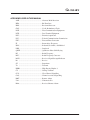
Acronyms Used in This Manual ................................................................................................... 49
Appendix A.
Cable Connections ...................................................................................................................... A-1
Terminal Connection (DB-25).................................................................................................... A-1
Personal Computer Connection (DB-9) ..................................................................................... A-1
Modem Connection (DB-25) ...................................................................................................... A-1
vi
TRACER 2 x E1 User’s Manual
61280004L2-1C
Table of Contents
Illustrations
Figure 1-1.
Typical Application .................................................................................................. 1
Figure 1-2.
Bandwidth Division ................................................................................................. 2
Figure 1-3.
BBP .......................................................................................................................... 3
Figure 1-4.
BBP Rear Panel ........................................................................................................ 3
Figure 1-5.
BBP Block Diagram ................................................................................................. 4
Figure 1-6.
BBP Front Panel (with door closed) ........................................................................ 6
Figure 1-7.
BBP Front Panel (with door open) ........................................................................... 6
Figure 1-8.
RFC Function Block Diagram ................................................................................. 8
Figure 1-9.
RFC Module ............................................................................................................. 8
Figure 1-10. Front and Rear of Rackmount RFC Housing ........................................................... 9
Figure 1-11. Mastmount RFC Housing ...................................................................................... 10
Figure 2-1.
E1 Loopback Locations ......................................................................................... 14
Figure 2-2.
2.4 GHz Diplexer ................................................................................................... 18
Figure 2-3.
5.8 GHz Diplexer ................................................................................................... 20
Figure 3-1.
System Status Screen ............................................................................................. 26
Figure 3-2.
Main Menu Screen ................................................................................................. 27
Figure 3-3.
System Configuration Menu Screen ...................................................................... 27
Figure 3-4.
E1A Status Screen .................................................................................................. 28
Figure 3-5.
E1B Status Screen .................................................................................................. 28
Figure 3-6.
Link Performance History Screen .......................................................................... 29
Figure 3-7.
E1A Statistics Screen ............................................................................................. 30
Figure 3-8.
E1B Statistics Screen ............................................................................................. 30
TRACER 2 x E1 User’s Manual
vii
61280004L2-1C
Table of Contents
viii
TRACER 2 x E1 User’s Manual
SECTION 1
TRACER DESCRIPTION
INTRODUCTION
The Dual E1 version of TRACER provides two, individual E1 transports via a 2.4 GHz or 5.8 GHz,
direct sequence, spread spectrum microwave link. The transmitter output power is 20 dBm maximum
while the receiver sensitivity is -89 dBm @ 2.4 GHz and -87 dBm @ 5.8 GHz. System performance is
determined, in part, by the engineering of the microwave link. Each TRACER radio is comprised of two
components – the baseband processor and the radio frequency converter (RFC). The E1 interfaces
(G.703, G.704 compliant) are provided on the back of the baseband processor, which is mountable in a
515 mm rack. The radio frequency converter is rackmountable adjacent to the baseband processor or
mastmountable in a weatherproof enclosure, located up to 110 meters apart, using RG-8 style coax. A
single coaxial cable connects the baseband processor (via a Type N connector) to the RFC and another
coaxial cable connects the RFC to the antenna (via a Type N connector).
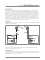
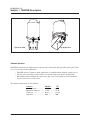
Applications
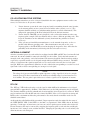
Any application that would typically use metallic E1 as a transport can use the TRACER instead. Figure
1-1 illustrates a typical application.
Antenna
Antenna
RF Cable
RF Cable
IF Cable
Rackmount RFC
TRACER Baseband
TRACER Baseband
VT-100
Processor
Processor
RS-232
Rackmount RFC
Terminal
E1
E1
E1
E1
E1 Equipment
E1 Equipment
E1, Mastmounted RFC
E1, Rackmounted RFC
Figure 1-1. Typical Application
In addition to telephony applications, TRACER can be used in data communications such as internetworking, video conferencing, and telemetry.
Spread Spectrum
Spread spectrum is a form of communication in which the bandwidth of a message signal is intentionally
increased or “spread.” There are two methods of spreading -- frequency hopping and direct sequence.
TRACER employs direct sequence spread spectrum.
TRACER 2 x E1 User’s Manual
1
61280004L2-1C
Section 1 TRACER Description
Direct Sequence
A direct sequence transmitter spreads the signal by mixing the data with the output of a pseudorandom
number generator which changes state at a rate higher than the data rate. This rate is called the
“chipping” rate. The TRACER chipping rate is twelve times the data rate.
Coding
Many different pseudorandom sequences exist. The sequences are called pseudorandom because,
although they appear noise-like, they are determinant and repeat after a specific number of chips. The
longer a code is, the better correlation characteristics it possesses. These traits allow multiple spread
spectrum systems to operate in the presence of one another with minimal interference if they are
operating with different sequences. The TRACER allows the selection of one of ten different 120-bit
long sequences.
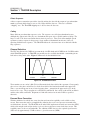
Channel Selection
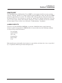
The FCC has allocated 83.5 MHz of spectrum in the 2.4 GHz band and 125 MHz in the 5.8 GHz band in
which TRACER operates. A TRACER system fully uses the available bandwidth – transmitting in one
half and receiving in the other. Figure 1-2 illustrates the bandwidth division.
2400 MHz
2441 MHz
2483.5 MHz
5725 MHz
or
5787 MHz
5850 MHz
Figure 1-2. Bandwidth Division
The transmitter at one end of a link (TxA) will transmit in the lower half of the spectrum. Consequently,
the receiver at the other end will receive in the lower half of the band and transmit in the upper half.
Thus, a system will operate in one of two frequency plans -- transmit in the upper and receive in the
lower or vice versa. These two plans are called Plan A and Plan B. One end of a path will be on Plan A
and the other will be on Plan B. Shipment of a link will consist of an A and a B unless specified
otherwise.
Forward Error Correction
With the addition of overhead data, error detection and correction capability can be added to a data
stream. Error correction can be accomplished by allowing the receiver to request to retransmit of the
erred block once detected. The TRACER, on the other hand, implements forward error correction (FEC)
which adds enough overhead data for the receiver to detect and correct errors in the data stream. This
capability comes at the cost of bandwidth. The addition of FEC decreases the required signal-to-noise
(S/N) ratio by approximately 5.5 dB to achieve a given bit error rate (BER).
2
TRACER 2 x E1 User’s Manual
61280004L2-1C
Section 1 TRACER Description
E1 Interfaces
The E1 interfaces conform to the ITU G.703 and G.704 electrical and signaling interface
recommendations. Two interfacing configurations are allowed - two pair of BNC coaxial connectors or
two 15-pin sub-D connectors and RJ48 connectors.
The coaxial connection provides a 75Ω unbalanced connection. The shield of the TX coaxial connection
is attached to earth ground. A strap is provided to optionally connect the shield of the RX coaxial
connection to ground as described in G.703. The 15 pin sub-D and RJ48 connection provides a 120Ω
balanced connection.
TRACER System Configuration
A TRACER system is composed of three major subsystems -- a baseband processor, a radio frequency
converter, and an antenna. The following section describes the system components.
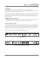
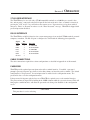
Baseband Processor or BBP
The baseband processor or BBP is a 1-U, 515 mm (19-inch) rackmountable unit. This unit provides the
system electrical interfaces, user controls and indicators, and performs the spread spectrum processing
for the system. The rear panel provides all of the electrical interface points -- E1 interfaces, VT100
compatible terminal, alarm contacts, IF signal, and DC power (from facility or optional AC adapter).
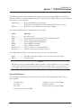
The BBP front and rear panels are illustrated in Figures 1-3 and 1-4.
E1A
E1B
ALM
ALM
FREQ
TRACER
SYSTEM
TEST
LBK
LBK
PLAN A
RF LOW
POWER
CV/CRC
LOS/OOF
CV/CRC
LOS/OOF
PLAN B
LINK DOWN
Figure 1-3. BBP
G.703
E1B
75 OHM
RS232
TX
RX
IF
E1A
MAJ
MIN
DC POWER
75 OHM
TX
RX
NO COM
NC
NO COM NC
Figure 1-4. BBP Rear Panel (75Ω Option)
TRACER 2 X E1 User’s Manual
3
61280004L2-1C
Section 1 TRACER Description
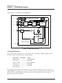
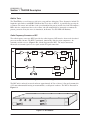
A block diagram of the BBP is shown in Figure 1-5.
RS-232
E1 A
E1
E1 B
E1
Baseband Processor Board
µC
UART
Data
Multiplexer
Fc = 140 MHz
IF
Filter
Spread
Spectrum
Data
Pump
Viterbi
Encoder/
Decoder
Σ
DSP
90
Fc = 70 MHz
90
IF Interface Board
21-56
VDC
Figure 1-5. BBP Block Diagram
VT100 RS-232 Interface
An RS-232 interface is provided via a 25-pin D connector for attaching a VT100 compatible terminal.
The active signals used on this interface are listed below
Signal Name Pin Number Source
Transmit Data .......... 2 ............. Terminal/Modem
Receive Data ............ 3 ............. TRACER
Request to Send ....... 4 ............. Terminal/Modem
Clear to Send ............ 5 ............. TRACER
Data Set Ready ........ 6 ............. TRACER
Signal Ground .......... 7
The management system allows the E1 interfaces to be provisioned. The line code can be selected as
AMI or HDB3. The signaling can be selected as channel associated signaling (CAS) or common channel
signaling (CCS). Alarm conditions can also be monitored. The management system will report the
following alarms on the E1 interfaces:
4
TRACER 2 x E1 User’s Manual
61280004L2-1C
Section 1 TRACER Description
•
•
•
•
•
•
Loss of signal
Code violation
CRC error
Framing error
Remote alarm
UA1
A seven-day error history of the E1 interfaces and radio link is also provided. Fifteen-minute histories
are provided for the most recent 24 hours of operation.
The status of the microwave link can also be monitored from the management system. The transmitter
power setting as well as an indication of the received microwave signal level are provided.
Alarm Contacts
Two classes of alarm, MAJOR and MINOR, are provided. A MAJOR alarm is signaled if, for any
reason, the microwave path is not operational. A MINOR alarm is signaled when the data path is
operating, but impaired. A minor alarm will be activated when an alarm is sensed on the E1 interfaces or
when the received RF signal level falls below approximately -80 dBm. Both normally-open and
normally-closed contacts are provided for each alarm class. Access is provided by a six-position terminal
strip on the back of the baseband processor.
IF Signal
The Type N Connector provides the interface point between the baseband processor and the radio
frequency converter (RFC). This connection provides the signal, power, and configuration information to
the RFC. A coaxial cable (ADTRAN part number 3125RF027 is provided for connecting the BBP to the
RFC for the rackmount model. Cable for connecting the BBP to a mastmount RFC must be provided by
the customer after the length of the cable has been determined.
Power
The unit receives power via one of two connectors. Power for the entire system is provided by these
interfaces. The 3 pin circular DIN connector is provided to connect an ADTRAN supplied desktop AC
adapter providing 48 volts DC. The three-pin terminal block allows the connection of any DC power
source providing between 21 and 60 volts DC. The power consumption of the entire system is
approximately 30 watts.
Controls and Indicators
The system may be configured via the front panel, which is accessible behind a drop-down panel on the
right half of the BBP. The front panel is illustrated in Figures 1-6 and 1-7.
TRACER 2 X E1 User’s Manual
5
61280004L2-1C
Section 1 TRACER Description
E1A
E1B
ALM
TRACER
SYSTEM
FREQ
ALM
TEST
LBK
LBK
PLAN A
RF LOW
POWER
CV/CRC
LOS/OOF
CV/CRC
LOS/OOF
PLAN B
LINK DOWN
Figure 1-6. BBP Front Panel with Door Closed
ALM
LBK
RESET
LBKA
90 1
3
4
HDB3 HDB3
CAS
CAS
78
TEST
2
45 6
23
1
ALM
LBK
GND
L
RSSI
+5
+12
A
TST
LBKB
RF LOW
TEST
UP
PWR
LOS
OOF
CV
CRC
E1A
CCS
CCS
AMI
AMI
LOS
OOF
CV
CRC
DOWN
CODE
TX PWR
B
CLK
Q
RF
PWR
-5
FAIL
LINK
-12
E1B
PLAN
REMOTE
ERROR
Figure 1-7. BBP Front Panel with Door Open
As a rule, a green LED indicates a normal situation, a red LED indicates an error situation, and a yellow
LED indicates a configuration option. LEDs indicating overall system integrity are listed below.
Self Test .................................... Blinking red if the self-test has completed and failed; Solid red if
self-test is in progress or did not complete
Power ........................................ Green if DC voltage is applied
The LEDs associated with the E1 interfaces are listed below.
CV/CRC .................................... Red if the incoming E1 stream contains code violations, or a CRC
error
LOS/OOF .................................. Red if there is no signal present at the E1 interfaces or if framing
synchronization is lost
Loopback................................... Solid yellow if the E1 interfaces are in local line loopback. Blinking
yellow if the E1 interfaces are in link loopback.
ALM .......................................... Solid red if a UA1 is detected at the incoming E1, blinking red if a
remote alarm signal is found
The functions of the LEDs which relate system configuration information are listed below.
Frequency Plan A...................... Yellow if frequency plan A is selected
Frequency Plan B ...................... Yellow if frequency plan B is selected
Remote Test Active .................. Yellow if the remote test is active
Remote Test Fail ....................... Red if the remote test failed
6
TRACER 2 x E1 User’s Manual
61280004L2-1C
Section 1 TRACER Description
The LEDs that indicate error conditions in the spread spectrum data pump and RFC are listed below.
All of these LEDs are visible through the front panel. Any one of these LEDs indicates an error condition
that precludes system operation.
Link Down .............. Red if the RF link is not operational.
E1 interfaces will transmit UA1 on the affected E1 to indicate an error.
RF Low ................... Red if the received RF carrier level is below -80 dBm.
The controls available from the control panel are listed below.
Name
Function
Reset ........................ Reset the system
LBK ......................... Toggles E1 between normal and local line loopback modes
CAS ......................... Selects Channel Associated Signaling
CCS ......................... Selects Common Channel Signaling
HDB3 ...................... Selects HDB3 Line Coding
AMI ......................... Selects AMI Line Coding
Remote Test ............ Initiate a remote test across the RF link
TX Power ................ Adjusts transmit power level up and down
The monitor points provided on the front panel of the system are described below.
RSSI ........................ DC voltage indicating strength of the received signal at the antenna
GND ........................ System ground
NOTE
The voltage level present at the RSSI test point represents a relative signal level of receive strength
from the far end. No direct correlation can be made between RSSI voltage level and actual receive
level in dBm. This test point is provided to assess relative signal level for alignment of antennae.
Non-volatile Memory
The TRACER system contains non-volatile memory to retain certain configuration settings. These
settings include:
Frequency plan
Password
Site name
E1 framing (if set from VT100)
TRACER 2 X E1 User’s Manual
Chipping code (if set from VT100)
Password enabling
E1 line coding (if set from VT100)
7
61280004L2-1C
Section 1 TRACER Description
Built-In Tests
The TRACER has several features to aid in site setup and later debugging. These diagnostics include E1
loopbacks and a link test with BERT (Bit Error Rate Test) data. A link test is performed by pressing the
test button. The remote unit will then send a pseudorandom data pattern, and the local end will compute a
BER. After the conclusion of the test, the remote end will automatically be instructed to terminate the
pattern generation. If any bit errors are introduced, the Remote Test Fail LED will illuminate.
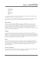
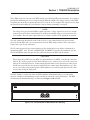
Radio Frequency Converter or RFC
The radio frequency converter (RFC) provides the radio frequency (RF) interface between the baseband
processor and the antenna. The RFC is partitioned, functionally, into two major components - the
transmitter and the receiver. Figure 1-8 is a block diagram of the RFC. The major connections
illustrated are transmit signal, receive signal, and the IF signal connection.
RX
SAW
LPF
Splitter
333
AGC
2018 or 5344
5324
2058
TX
IF
PA
Splitter
AGC
2321 or 5607
5687
2281
Figure 1-8. RFC Block Diagram
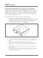
The RFC unit is enclosed in a metal enclosure approximately 26.7cm x 14cm x 2.5cm and is mounted in
a 515 mm rackmountable housing or mastmountable, weatherproof enclosure. The RFC is illustrated in
Figure 1-9.
RSSI
GND
RX
TX PWR
IF
TX
Figure 1-9. RFC Module
8
TRACER 2 x E1 User’s Manual
61280004L2-1C
Section 1 TRACER Description
Three SMA connectors, located on the RFC module, provide RF and IF connection points. A test point is
provided for monitoring the received signal strength indicator (RSSI). The voltage (relative to the GND
test point) present on this test point represents the level of the received signal. This signal is used to align
the antenna when installing the system and to verify the link is performing as designed.
NOTE
The voltage level present at the RSSI test point represents a relative signal level of receive strength
from the far end. No direct correlation can be made between RSSI voltage level and actual receive
level in dBm. This test point is provided to assess relative signal level for alignment of antennae.
The only connections that must be made in the field are a coax connection between the baseband
processor and the RFC and a coax connection between the RFC and the antenna. These connections
require male, type N coax connectors.
The IF connector provides the connection between the baseband processor and the rackmounted or
mastmounted RFC. An 8” IF cable (ADTRAN P/N 3125RF027) is provided for rackmount systems.
The TO ANTENNA connection provides the connection between the RFC and the antenna.
CAUTION
When connecting an RF converter (RFC) to a Baseband Processor (BBP), verify that the connector
labeled “IF” on the rear panel of the Baseband Processor is connected via coax to the connector
labeled “IF” on the RF converter. Connecting the Baseband Processor to the incorrect connector on
the RF converter will cause the internal 1 amp 250 V fuse to blow in the Baseband Processor. This
fuse is accessed by removing the top of the Baseband Processor, and is located on the left side of the
chassis when facing the front panel.
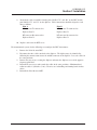
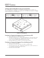
The RFC module is enclosed in either an ETSI-compliant rackmount housing or a weather-tight
enclosure suitable for mastmounting near the antenna for enhanced system performance. The RFC
mastmount and rackmount housings are illustrated in Figures 1-10 and 1-11.
TRACER
IF
ANTENNA
Figure 1-10. Front and Rear of Rackmount RFC Housing
TRACER 2 X E1 User’s Manual
9
61280004L2-1C
Section 1 TRACER Description
Holes
for Mounting Bracket
Mounting Clearances
Housing Assembly and Guide
WARNING
Eye Level View
Up Angle View
Figure 1-11. Mastmount RFC Housing
Antenna Selection
TRACER is intended to be coupled with an antenna that is directional (thus providing signal gain). There
are several reasons for this requirement:
• TRACER operates in point-to-point applications so omnidirectional antennas cannot be used.
• The low power transmitter is intended to be used with a high-gain antenna for long links.
• Directional antennas minimize the interference that a site is susceptible to and also minimize
the site’s interference to other sites.
The antenna requirements are listed below.
Antenna
100 mW
Minimum gain .................... 15 dBi .............
Minimum return loss .......... 15 dB ..............
Connector ........................... N-type .............
Impedance .......................... 50Ω .................
10
1W
6 dBi
15 dB
N-type
50Ω
TRACER 2 x E1 User’s Manual
I
61280004L2-1C
2 Installation
SECTIONSection
2 NSTALLATION
UNPACK, INSPECT
Carefully inspect the TRACER for any shipping damages. If damage is suspected, file a claim
immediately with the carrier then contact ADTRAN Customer Service. If possible, keep the original
shipping container for use in shipping the TRACER back for repair or for verification of damage during
shipment.
Before beginning installation, verify that all of the following components are present.
Rackmounted RFC Configuration:
Provided by ADTRAN
• Baseband Processor (BBP)
• Rackmounted RF Converter (RFC)
• BBP to RFC IF interconnect cable
Provided by customer
• E1 Interface cables
• Antenna feedline cable
• Antenna and mounting hardware
• VT100 terminal and RS-232 interface cable (optional)
• 21 to 60 volt DC power source (available from ADTRAN), either
polarity referenced to ground
Mastmounted RFC Configuration:
Provided by ADTRAN
• Baseband Processor
• Mastmounted RF Converter
Provided by customer
• E1 interface cables
• Antenna feedline cable
• Antenna and mounting hardware
• BBP to mastmounted RFC IF interconnect cable
• VT100 terminal and RS-232 interface cable (optional)
• 21 to 60 volt DC power source (available from ADTRAN), either
polarity referenced to ground
INSTALLATION
Location and Mounting
Install the TRACER in a location that requires minimal antenna feedline length (the loss in this cable
directly affects overall system performance). When used with a rackmount RFC the BBP is designed to
be mounted above the RFC. Although no space is needed between the units, certain regulations may
require at least 19.05 mm (.75") of space above and below the BBP.
Power Requirements
The TRACER can operate from a supply between 21 and 60 volts DC, with either polarity referenced to
ground, and consumes 30 watts. Amperage is determined by dividing the wattage (30) by the input
voltage (i.e., 30 watts/48 volts = .625 amps).
TRACER 2 x E1 User’s Manual
11
61280004L2-1C
Section 2 Installation
Grounding
The following grounding instructions are derived from the Underwriters’ Laboratory UL 1459
Standard for Safety: Telephone Equipment dated September 20, 1993.
An equipment grounding conductor that is no smaller in size than the ungrounded branch-circuit supply
conductors is to be installed as part of the circuit that supplies the product or system. Bare, covered, or
insulated grounding conductors are acceptable. Individually covered or insulated equipment grounding
conductors shall have a continuous outer finish that is either green, or green with one or more yellow
stripes. The equipment grounding conductor is to be connected to ground at the service equipment.
The attachment-plug receptacles in the vicinity of the product or system are all to be of a grounding type,
and the equipment grounding conductors serving these receptacles are to be connected to earth ground
at the service equipment.
A supplementary equipment grounding conductor shall be installed between the product or system and
ground that is in addition to the equipment grounding conductor in the power supply cord.
The supplementary equipment grounding conductor shall not be smaller in size than the ungrounded
branch-circuit supply conductors. The supplementary equipment grounding conductor shall be
connected to the product at the terminal provided, and shall be connected to ground in a manner that
will retain the ground connection when the product is unplugged from the receptacle. The connection to
ground of the supplementary equipment grounding conductor shall be in compliance with the rules for
terminating bonding jumpers at Part K or Article 250 of the National Electrical Code, ANSI/NFPA 70.
Termination of the supplementary equipment grounding conductor is permitted to be made to building
steel, to a metal electrical raceway system, or to any grounded item that is permanently and reliably
connected to the electrical service equipment ground.
Bare, covered, or insulated grounding conductors are acceptable. A covered or insulated grounding
conductor shall have a continuous outer finish that is either green, or green with one or more yellow
stripes.
The supplemental equipment grounding terminals are located on the rear of the BBP adjacent to the
power connectors and on the rear of the rackmounted RFC. The mastmounted RFC has a ground lug
mounted on the installation bracket.
12
TRACER 2 x E1 User’s Manual
61280004L2-1C
Section 2 Installation
E1 Interfaces
The E1 interface conforms to the ITU G.703 and G.704 electrical and signaling interfaces
recommendations. Two interfacing configurations are available:
• 75Ω unbalanced BNC coaxial connectors.
• 120Ω balanced 15 pin / RJ48 connectors with the pinouts shown here.
15 Pin
Pin
Function
1
2
3
4
5
6
7
8
9
10
11
12
13
14
15
E1 Out ring
Frame ground
E1 In ring
Frame ground
N.C.
N.C.
N.C.
N.C.
E1 Out tip
N.C.
E1 In tip
N.C.
N.C.
N.C.
N.C.
RJ-48
Pin
Function
1
2
3
4
5
6
7
8
E1 Out ring
E1 Out tip
N.C.
E1 In ring
E1 In tip
N.C.
N.C.
N.C.
The 75Ω unbalanced interface provides two pair of 75Ω BNC connectors. The shield of the OUT
coaxial connection is attached to earth ground. A jumper is provided to optionally connect the shield of
the INPUT coaxial connection to ground as described in G.703. This jumper is located on the inside of
the E1 interface board, between each of the two BNC connectors. The E1 module must be removed to
access this option.
The 120Ω balanced interface provides two individual 120Ω 15-pin connectors.
TRACER 2 x E1 User’s Manual
13
61280004L2-1C
Section 2 Installation
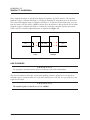
Three loopback functions are provided for diagnostic capability of each E1 interface. The local line
loopback (Loop 1 as illustrated in Figure 2-1) loops the incoming E1 signal back out at the E1 framer.
The remote link loopback (Loop 3 as illustrated in Figure 2-1) loops the E1 data back to the local end
from the remote end. This allows a BERT to be run across the microwave link and back. The local link
loopback (Loop 2 as illustrated in Figure 2-1) allows the local unit to loop E1 data back towards the
remote end. The available loopback functions are illustrated in Figure 2-1.
E1
1
2
Local
RF Link
3
E1
Remote
Figure 2-1. E1 Loopback Locations
LINK PLANNING
IMPORTANT
The appropriate transmitter power must be calculated as part of the link planning.
The factors that must be taken into account when planning a link are optimal received signal level,
transmitter power, antenna feedline loss (each end), antenna gain (each end), free space path loss, and
required fade margin.
IMPORTANT
The optimal signal level for the receiver is -60 dBm.
14
TRACER 2 x E1 User’s Manual
61280004L2-1C
Section 2 Installation
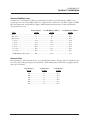
Antenna Feedline Loss
Feedline loss is a function of feedline type and length. Feedline loss per 30.48 meters (100 feet) for
several types of coax at IF and RF frequencies is detailed in the table below. The IF loss applies to BBP/
RFC interconnection, and the RF loss applies to RFC/antenna interconnection. Cable manufacturers’
specifications may vary.
IF Loss/100 feet 2.4 GHz RF Loss/100 feet
5.7 GHz RF Loss/100 feet
Cable
(in dB)
(in dB)
(in dB)
RG58 ..................................................... 5.7 ................................... 80 ............................................ N/A
RG8 (air) ............................................... 2.7 ................................... 20 ............................................ N/A
RG8 (foam) ............................................ 2 ...................................... 9 ............................................. N/A
1
/4" Coax ............................................... 1.42 ................................ 5.91 ......................................... 11.36
3
/8" Coax ............................................... 1.25 ................................ 5.76 .......................................... 9.65
1
/2" Coax ............................................... 0.81 ................................ 3.83 .......................................... 6.49
7
/8" Coax ............................................... 0.44 ................................. 2.2 ............................................ N/A
1 1/4" Coax ............................................ 0.33 ................................ 1.62 ........................................... N/A
1 5/8" Coax ............................................ 0.27 ................................ 1.41 ........................................... N/A
5.8 GHz Elliptical Waveguide ............. N/A ................................ N/A .......................................... 1.23
Antenna Gain
Best performance will result from the use of a parabolic dish antenna. Antenna gain is determined by the
size of the dish, with typical figures detailed below. Dish manufacturers will be able to supply gains for
other types of antenna.
Dish Diameter
(in cm)
2.4 GHz Gain
(in dBi)
60 .................................... 21
120 ................................... 27
180 ................................... 31
243 ................................... 33
304 ................................... 35
365 ................................... 37
TRACER 2 x E1 User’s Manual
5.8 GHz Gain
(in dBi)
.............................. 28.5
.............................. 34.2
.............................. 37.5
.............................. 40.7
.............................. 42.5
.............................. 44.2
15
61280004L2-1C
Section 2 Installation
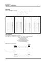
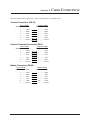
Path Loss
The free space path loss is given by
Loss(dB) = 96.6 + 20 log10 f + 20log10D * 1.609344
where D is distance in kilometers
f is operating frequency in GHz
A tabulation of various path loss is given below.
2.4 GHz
Link Distance Path Loss
(in miles)
(in dB)
1 ................. 104
2 ................. 110
3 ................. 114
4 ................. 116
5 ................. 118
6 ................. 120
7 ................. 121
8 ................. 122
9 ................. 123
10 ................ 124
11 ................ 125
12 ................ 126
2.4 GHz
Link Distance Path Loss
(in miles)
(in dB)
13 ................ 126
14 ................ 127
15 ................ 128
16 ................ 128
17 ................ 129
18 ................ 129
19 ................ 129
20 ................ 130
21 ................ 130
22 ................ 131
23 ................ 131
24 ................ 132
5.8 GHz
Link Distance Path Loss
(in miles)
(in dB)
1 ................ 112
2 ................ 118
3 ................ 121
4 ................ 124
5 ................ 126
6 ................ 127
7 ................ 129
8 ................ 130
9 ................ 131
10 ............... 132
11 ............... 133
12 ............... 133
5.8 GHz
Link Distance Path Loss
(in miles)
(in dB)
13 ............... 134
14 ............... 135
15 ............... 135
16 ............... 136
17 ............... 136
18 ............... 137
19 ............... 137
20 ............... 138
21 ............... 138
22 ............... 139
23 ............... 139
24 ............... 139
Path Availability
The availability of a path can be expressed by:
availability = (1 - C x T x 2.5 x 10⁻⁶ x f x (D x 1.609344)3 x 10-(F/10)) x 100%
where C is the climate factor
T is the terrain factor
f is the frequency in GHz
D is the path length in kilometers
F is the fade margin in dB
Climate factors are given below.
Climate
Climate
Factor
Very Dry ............................................................. 1/8
Temperate ........................................................... 1/4
Humid ................................................................. 1/2
Terrain factors are listed below.
Terrain
Terrain
Factor
Smooth ................................................................ 4
Average ............................................................... 1
Mountainous ...................................................... 1/4
16
TRACER 2 x E1 User’s Manual
61280004L2-1C
Section 2 Installation
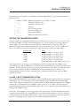
The nominal received signal level is -60 dBm. For help in link planning, use the path loss calculation
worksheet below.
+
+
+
+
=
89 dBm / -87 dBm
_______
_______
_______
_______
_______
_______
_______
Minimum Signal Power for 2.4 GHz / 5.8 GHz
Transmitter Feedline Loss
Transmitter Antenna Gain
Path Loss
Receiver Antenna Gain
Receiver Feedline Loss
Required Fade Margin
(dBm) Transmitter Power Setting
SETTING THE TRANSMITTER POWER
The FCC specifies the maximum transmitter power that may be used for antennas of a given gain. FCC
rules Part 15, Subpart 247 allow for a maximum power of 1 watt into antennae of a gain less than or
equal to 6 dBi. For every 3 dB of gain over 6 dBi, the transmitter must be reduced by 1 dB. The
following table lists the maximum transmitter power for given antennae gains. For the 5.8 GHz band,
there is no reduction in transmitter output power required for antenna gains greater than 6 dBi.
Antenna Gain
6 dBi
12 dBi
18 dBi
24 dBi
30 dBi
36 dBi
Power
30 dBm (2.4 GHz, 1 watt output option)
28 dBm (2.4 GHz, 1 watt output option)
26 dBm (2.4 GHz, 1 watt output option)
24 dBm (2.4 GHz, 1 watt output option)
22 dBm (2.4 GHz, 1 watt output option)
20 dBm (TRACER, 2.4 GHz, 100 mw output option)
The transmitter power is set by way of a momentary switch on the front panel of the BBP or via the
configuration page of the VT100 interface. The RFC must be attached by way of the IF cable during this
operation. Attach an RF power meter to the N-type antenna connector on the RFC, and adjust the power
by way of the front panel switch or VT100 until the desired transmitter power is obtained. If a
mastmount RF converter is used, the transmitter power adjustment should be made before the RFC is
installed on the mast.
2.4 GHZ, 1 WATT TRANSMITTER OPTION
The 2.4 GHz TRACER model is offered with a standard +20 dBm power output or optional 1 watt power
output option. The 1 watt option provides an add-on amplifier that is installed in the rackmount RFC
chassis. This amplifier is connected to the transmit cable of the RFC module and amplifies the +20 dBm
output power to a maximum level of +30 dBm (1 watt), factory set to +27 dBm. The output power is
proportional to the output level from the RFC module. The level is adjusted via the Baseband Processor
front panel or VT100 terminal.
Because the 1 watt amplifier is frequency specific, the frequency plans can not be manually changed by
swapping the TX and RX cables in the RFC chassis as described in the following section. If a frequency
reversal is required, the rackmount RFCs will have to be relocated to the opposite ends of the microwave
path. The 1 watt option is only available for the 2.4 GHz, rackmount RF converter.
TRACER 2 x E1 User’s Manual
17
61280004L2-1C
Section 2 Installation
SETTING THE RFC FREQUENCY PLAN ON NON 1 WATT 2.4 GHZ MODELS
The frequency plan designates on which frequencies the TRACER transmits and receives. Plan A
corresponds to a transmitting (Tx) center frequency of 2422 MHz and a receive (Rx) center frequency of
2462 MHz. Plan B corresponds to a Tx center frequency of 2462 MHz and a Rx center frequency of
2422 MHz. Shipment of a link consists of one RFC set to Plan A and the other set to Plan B unless
specified otherwise. The RFC plan can, however, be changed in the field if required. This procedure
involves reconfiguring the RFC interconnect cables.
For rackmounted systems, do the following to reconfigure the RFC interconnect:
1. Remove the six screws which retain the RFC cover and remove the cover.
2. The RF unit may be identified by following the connection from the port labelled “IF” on the
rear of the RFC. This connection terminates at the RF unit. The diplexer may be identified
by following the connection from the “Antenna” port on the rear of the RFC. This
connection terminates at the diplexer, illustrated in Figure 2-2.
J1
AN
T
J2
Figure 2-2. 2.4 GHz Diplexer
3. Unscrew the cable assemblies from the ports labelled “Tx” and “Rx” on the RFC, and the
ports labelled “J1” and “J2” on the diplexer, depending on the frequency Plan (Plan A or
Plan B).
4. Unscrew the cable assembly from the port labelled “ANT” on the diplexer.
5. Remove the four screws from the bottom of the RFC that hold the diplexer in place.
6. Turn the diplexer over revealing the opposite frequency plan (from Plan A to Plan B, or vice
versa).
7. Realign the diplexer with the screw holes and replace the four screws that attach it to the
bottom of the RFC.
8. Reattach the loose cable assembly (from step 4) to the port labelled “Antenna” on the
diplexer. Minimum bend radius on cables is 3/4 inches (2 cm). Exercise care in handling
and forming bends in these cables.
18
TRACER 2 x E1 User’s Manual
61280004L2-1C
Section 2 Installation
9.
Reattach the cable assemblies from the ports labelled “Tx” and “Rx” on the RFC and the
ports labelled “J1” and “J2” on the diplexer. Cable connections should be aligned to each
other as follows.
Plan A
Plan B
RF converter Tx connected to
RF converter Tx connected to
Diplexer Port J1
Diplexer Port J2
RF converter Rx connected to
Diplexer Port J2
RF converter Rx connected to
Diplexer Port J1
10. Replace and secure the RFC cover.
For mastmounted systems, do the following to reconfigure the RFC interconnect:
1.
2.
3.
4.
5.
Remove the lid of the mast RFC.
Disconnect the three cables attached to the diplexer. The diplexer may be identified by
following the antenna connector to the middle connector of the diplexer. Leave the cables in
the same positions.
Remove the two screws securing the diplexer and rotate the diplexer to reveal the opposite
frequency plan label.
Reinstall the two screws and reattach the cables in the same positions – Minimum bend
radius on cables is 3/4 inches (2 cm). Exercise care in handling and forming bends in these
cables.
Reinstall the lid of the mast RFC.
TRACER 2 x E1 User’s Manual
19
61280004L2-1C
Section 2 Installation
SETTING THE RFC FREQUENCY PLAN ON 5.8 GHZ MODELS
The 5.8 GHz RFC operates on Plan A, Tx = 5747 MHz center frequency, Rx = 5827 MHz center
frequency or Plan B, Tx = 5827 MHz center frequency, Rx = 5747 MHz center frequency. See Figure
2-3 for an illustration of the 5.8 GHz diplexer.
Plan A
RFC “Tx” connected to diplexer “CHAN 1”
RFC “Rx” connected to diplexer “CHAN 2”
Plan B
RFC “Tx” connected to diplexer “CHAN 2”
RFC “Rx” connected to diplexer “CHAN 1”
AN
T
CH
A
N
1
CH
AN
2
Figure 2-3. 5.8 GHz Diplexer
Directions for Changing the Frequency Plan on the Rackmount RFC
1.
2.
3.
Remove RFC top cover by removing six screws.
Disconnect the cables at the “Tx” and “Rx” RFC module ports. Swap and reconnect these
two cables to the RFC module ports. Minimum bend radius on these cables is 3/4 inch
(2 cm). Use care in handling and forming bends in these cables.
Reinstall the RFC top cover with the six screws previously removed.
Directions for Changing the Frequency Plan on the Mastmount RFC
1.
2.
3.
4.
20
Remove the lid of the Mast RFC.
Disconnect the two cables at both ends; at the diplexer and RFC module.
Swap and reconnect these cables. Minimum bend radius on these cables is 3/4 inch. Use
care in handling and forming bends in these cables.
Reinstall the lid of the Mast RFC.
TRACER 2 x E1 User’s Manual
61280004L2-1C
Section 2 Installation
CONNECTING THE BBP AND THE RFC
The BBP and the RFC are connected by an IF cable, either supplied by ADTRAN (for rackmount
assembly) or by the customer (for mastmount assembly). This single connection provides everything the
RFC requires. The cable assembly attaches to the ports labeled “IF” on the BBP and the RFC.
CAUTION
When connecting an RF converter (RFC) to a Baseband Processor (BBP), verify that the connector
labeled “IF” on the rear panel of the Baseband Processor is connected via coax to the connector
labeled “IF” on the rear panel of the RF converter. Connecting the Baseband Processor to the
incorrect connector on the RF converter will cause the internal 1 amp 250 V fuse to blow in the
Baseband Processor. The fuse is accessed by removing the top of the Baseband Processor, and is
located on the left side of the chassis when facing the front panel.
APPLYING POWER
If the ADTRAN-supplied tabletop power source is used, simply plug it into the circular receptacle
located in the “DC Power” area on the rear of the BBP. If a source of 21 to 60 volts DC (30 watts),
either polarity referenced to ground is available, it may be attached to the terminal block located on the
rear of the BBP. Ground (or common) should be applied to the terminal with the ground symbol (Terminal 1)
and positive or negative voltage should be applied to the “+/-” terminal (Terminal 3). When a positive voltage
reference power supply is used (+24V for example), connect the ground (or “-”) cable from the power supply
to the ground terminal (Terminal 1) and the “+” cable from the power supply to the “+/-” terminal (Terminal
3). When a negative reference power supply is used (-48V for example), connect the ground cable from the
power supply to the ground terminal (Terminal 1) and the “-” cable from the power supply to the “+/-”
terminal (Terminal 3).
CAUTION
Power sources must not be attached to both the circular connector and the terminal blocks at
the same time or damage will occur.
AUTOMATIC BBP FREQUENCY PLAN
Upon the initial application of power, the BBP will default to the factory-preset Frequency Plan, or to the
Frequency Plan determined by the cable configuration of the RFC. The LED will indicate which
frequency plan is active. On subsequent reboots, such as after a loss of power, the BBP will default to
the most recently-used Plan setting.
SPREADING CODE
The spreading code for each end must be the same. The choice of operating code is selectable by the
operator or the installer. TRACER is shipped in a matched (default) configuration.
WARNING
Spreading code to be set through the VT100 interface from the other end of the link. If the new
spreading code is unknown, step the local end of the link through all other spreading codes until
the link is reestablished.
TRACER 2 x E1 User’s Manual
21
61280004L2-1C
Section 2 Installation
CO-LOCATING MULTIPLE SYSTEMS
When multiple transmitters are to be co-located (installed in the same equipment room or on the same
tower), it is advised to set all systems as follows:
1.
2.
3.
If more than one system in the same frequency band is transmitting from the same location,
set the antenna polarity of one system horizontal and the other system(s) vertical. (The
antennas should be marked as to which mounting position is vertical or horizontal.) This
will provide approximately 30 dB of isolation between the different antennas.
If more than one TRACER system is installed, set the co-located transmitters to the same
frequency plan (example: Plan A or Plan B) and set each to a different spreading code. This
keeps the transmitters on the additional system(s) from interfering with the co-located
receiver(s).
If the systems are from different manufacturers, set the transmit frequencies as close as
possible with different spreading codes. Other manufacturers may not use the exact
frequency plans as the TRACER system, but keeping the frequencies close will reduce the
probability of the transmitter(s) interfering with the co-located receiver(s).
ANTENNA ALIGNMENT
After the transmitter power for each end has been adjusted and the BBP and RFC have been installed and
connected, the antenna should be connected to the RFC via the feedline. Verify that both antennas are
arranged on the same polarity: vertical or horizontal. The antennas should be aimed toward one another
as precisely as possible and the received signal strength indicator (RSSI) voltage measured. The RSSI
voltage is a function of the signal strength at the receiver and is used to measure the received signal
strength. RSSI varies approximately from 0 to >4 volts, with 0 volts corresponding to a weaker received
signal and 4 volts or better corresponding to a stronger received signal.
NOTE
The voltage level present at the RSSI test point represents a relative signal level of receive strength
from the far end. No direct correlation can be made between RSSI voltage level and actual receive
level in dBm. This test point is provided to assess relative signal level for alignment of antenna.
RF LOW
The “RF Low” LED indicates that the received signal is within 10dB of the minimum received signal
strength (RSL < approximately -80 dBm). If this indicator is on, the link performance may be marginal.
The antennas should be peaked in azimuth and elevation until the desired signal level is achieved. RSSI
may be monitored on either the RF unit or the front of the BBP. If the received signal is too strong and
RSSI reaches a maximum such that the peak cannot be discerned, then the transmitter on the far end
should be turned down.
At this point the radio link should be operational. Proper operation can be determined by the status of
the “LINK DOWN” LED. If this LED is on, the link is not operational. If this LED is not on, the link is
operating. Certain types of interference can cause one end of a path to operate and the other end to fail.
In some instances, this may be corrected by swapping the frequency plan at each end, thus avoiding the
interference if it is stronger at one end than the other. Changing the spreading code at each end may also
allow interference to be mitigated.
22
TRACER 2 x E1 User’s Manual
61280004L2-1C
Section 2 Installation
REMOTE BERT
The TRACER includes a Bit Error Rate Tester (BERT) to verify that the installed system is operating
correctly. When the “Remote Test” button is pushed on the local BBP, the remote end will send a BERT
pattern for approximately ten seconds. The “Remote TST” indicator will turn yellow and remain on for
the duration of the test. If no bit errors are detected, the “Remote TST” indicator will turn off. If any bit
errors are detected, the “Remote Fail” indicator will turn red. This test should be run after the radio link
has been aligned. If the test fails, refer to Section 4, “Troubleshooting,” for guidance.
ALARM CONTACTS
Two classes of alarm, MAJOR and MINOR, are provided. A MAJOR alarm is signaled when the
microwave path is not operational. A MINOR alarm is activated when any of the following conditions
are detected at one of the E1 interfaces:
Loss of Signal
Code Violation
CRC error
Framing Error
Remote Error
UA1
Both normally-open and normally-closed contacts are provided for each alarm class. Access is provided
by a six-position terminal strip on the baseband processor.
TRACER 2 x E1 User’s Manual
23
61280004L2-1C
Section 2 Installation
24
TRACER 2 x E1 User’s Manual
SECTION 3
OPERATION
VT100 USER INTERFACE
The TRACER may be accessed with a VT100 compatible terminal set to 9600 bits per second, 8 data
bits, and no parity, connected to the RS-232 port on the back of the unit. Once a terminal is connected,
pressing the “Ctrl” and “L” keys will redraw the current screen. If password access has been enabled,
then press “Enter” or “Return” in order to see the “Enter Password:” message. TRACER is shipped with
password protection disabled.
RS-232 INTERFACE
The TRACER has an RS-232 interface for system management via an attached VT100 terminal, personal
computer, or modem. The RS-232 port is configured as a DCE with the following pin assignments:
Signal
Pin
Name Number
TXD
2
RXD
3
RTS
4
CTS
5
DSR
6
Ground
7
Direction
To TRACER
From TRACER
To TRACER
From TRACER
From TRACER
CABLE CONNECTIONS
The cable connections required for various configurations are detailed in Appendix A of this manual.
PASSWORD
TRACER provides optional password protection of the terminal interface. If enabled, a password
prompt is presented at power-up, reboot, or after thirty minutes of inactivity on the terminal. The default
configuration is “No password.” Password protection is enabled via the configuration menu. The
password is also set via the configuration menu.
If the password is forgotten, physical access to TRACER is required to access the terminal interface.
The password may be bypassed by holding in the LPBK A button while the system is rebooted. This will
bring up the terminal interface and allow the password to be changed or disabled via the configuration
screen.
CAUTION
This procedure is service-affecting.
TRACER 2 x E1 User’s Manual
25
61280004L2-1C
Section 3 Operation
MAIN MENU SELECTIONS
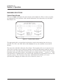
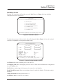
System Status Screen
The screen in Figure 3-1 displays the status of major system components. This is a status screen only;
no configurations can be performed. More detailed information can be obtained by way of the Main
Menu (Figure 3-2).
TRACER SYSTEM STATUS
ELAPSED TIME: 00000 DAYS, 00:00:07
ADTRAN TECHNICAL SUPPORT - 256/963-8716
--------E1A ===| C | / ->>---->>---->>----[ RF UP ]---->>---->>---->>- \ | C |=== E1A
| S |#(-)#| S |
E1B ===| U | \ -<<----<<----<<----[ RF UP ]----<<----<<----<<- / | U |=== E1B
--------LOCAL TRACER
REMOTE TRACER
FREQ PLAN B
FREQ PLAN A
SITE: ADTRAN
MIN
NOM
[###################_]
RX POWER
MIN
MAX
[####################]
TX POWER
RFC LINK UP:
CODE SYNC:
CARRIER SYNC:
E1 MUX SYNC:
CHIPPING CODE:
YES
YES
YES
YES
0
MIN
NOM
[###################_]
RX POWER
MIN
MAX
[####################]
TX POWER
=============================================================================
PRESS ‘M’ - MAIN MENU:
Figure 3-1. System Status Screen
The upper portion of the screen indicates how long the system has been running since the last reset
operation. The “E1A” and “E1B” labels will be highlighted if any error conditions exist on that E1
interface.
The status of the radio link is indicated as Up or Down. The left portion of the screen reports the status
of the local system (the system to which the terminal is attached); the right portion reports the status of
the remote system. The approximate transmitter and receiver signal levels are shown via the bar graphs.
If the link is down and remote end data is unavailable, the bar graphs will show “-” instead of “x.” RFC
Link Up indicates if communications exist on the IF cable connecting the baseband processor to the radio
frequency converter. The Code Sync, Carrier Sync, and E1 Mux Sync will all be “yes” for an
operational link. Chipping code indicates the code to which the system is set.
26
TRACER 2 x E1 User’s Manual
61280004L2-1C
Section 3 Operation
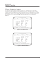
Main Menu Screen
Pressing “M” on any screen will take the user to the Main Menu (see Figure 3-2), from which the
subsequent screens can be accessed.
TRACER MAIN MENU
ELAPSED TIME: 00000 DAYS, 00:00:07
===============================================================================
0)
TRACER STATUS PAGE
1)
TRACER SYSTEM CONFIGURATION MENU
2)
TRACER LINK PERFORMANCE HISTORY
3)
E1A STATUS/CONFIGURATION/LOOPBACK MENU
4)
E1A PERFORMANCE HISTORY
5)
E1B STATUS/CONFIGURATION/LOOPBACK MENU
6)
E1B PERFORMANCE HISTORY
===============================================================================
PRESS MENU NUMBER, OR [ARROW KEYS] - MOVE UP AND DOWN, [SPACE] - SELECT:
Figure 3-2. Main Menu Screen
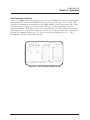
To make changes to any of the items in the System Configuration Menu (Figure 3-3), use the keyboard
Arrow keys to highlight desired option and make change.
TRACER SYSTEM CONFIGURATION
ELAPSED TIME: 00000 DAYS, 00:00:07
===============================================================================
RX POWER:
LOCAL TRACER
------------MIN
NOM
[###################_]
REMOTE TRACER
------------MIN
NOM
[###################_]
TX POWER:
MIN
MAX
[####################]
MIN
MAX
[####################]
CHIPPING CODE:
0
SITE NAME:
ADTRAN LOCAL
MODEM CONTROL:
ON
PASSWORD ENABLE: NO
PASSWORD:
*******
FRONT PANEL LOCK: ON
PERFORMANCE STATS:CLEAR
0
ADTRAN REMOTE
OFF
NO
*******
OFF
CLEAR
(*) —INDICATES THAT SETTING DIFFERS FROM THE FRONT PANEL
===============================================================================
PRESS ‘M’ - MAIN MENU, ‘U’,’D’ - MOVE UP AND DOWN, [SPACE] - SELECT:
Figure 3-3. System Configuration Menu Screen
Set Tx Power allows the transmitter power to be adjusted.
Set Chipping Code allows the chipping code to be selected. Each end of the link must be configured for
the same chipping code.
Site ID allows a string of up to 32 characters to be entered as a site identifier.
Enable/Disable Password allows password protection to be enabled or disabled. The default setting is
Disabled.
Change Password allows the password to be set.
Performance Stats resets all the error counters.
TRACER 2 x E1 User’s Manual
27
61280004L2-1C
Section 3 Operation
E1 Status / Configuration / Loopback
The status of the two E1 interfaces is displayed on this screen. Information such as alarm status,
signaling, line coding, and CRC4 Detection framing type are shown. From this screen the E1 can be
configured for a particular application by using the keyboard cursor keys to highlight the desired option
and perform the change. A local or remote loopback may be activated or deactivated from this screen.
The E1A Status Screen is illustrated in Figure 3-4, and the E1B Status Screen is illustrated in
Figure 3-5.
E1A STATUS/CONFIGURATION/LOOPBACK
RX ==>|----|->>---->>---->>----{
RF
}---->>---->>---->>-|-+
|
| LOCAL
{/\/\/\/\}
REMOTE | |
TX <==|----|-<<----<<----<<----{
UP
}----<<----<<----<<-|-+
LOCAL TRACER
-----------UA1 RMT LOS
OOF CV CRC
REMOTE TRACER
------------UA1
LOS
E1 INTERFACE TYPE:
120 OHM
75 OHM
ALARM REPORTING:
CRC4 DETECTION:
SIGNALING:
LINE CODE:
ENABLED
ENABLED
CAS
HDB3
DISABLED
ENABLED
CAS
HDB3
LOOP/NORMAL STATE:
NORMAL
NORMAL
E1 INTERFACE ALARMS:
|==> TX
|
|X== RX
(*) —INDICATES THAT SETTING DIFFERS FROM THE FRONT PANEL
===============================================================================
PRESS ‘M’ - MAIN MENU, ‘U’,’D’ - MOVE UP AND DOWN, [SPACE] - SELECT:
Figure 3-4. E1A Status Screen
E1B STATUS/CONFIGURATION/LOOPBACK
RX ==>|----|->>---->>---->>----{
RF
}---->>---->>---->>-|-+
|
| LOCAL
{/\/\/\/\}
REMOTE | |
TX <==|----|-<<----<<----<<----{
UP
}----<<----<<----<<-|-+
LOCAL TRACER
-----------UA1 RMT LOS
OOF CV CRC
REMOTE TRACER
------------UA1
LOS
E1 INTERFACE TYPE:
120 OHM
75 OHM
ALARM REPORTING:
CRC4 DETECTION:
SIGNALING:
LINE CODE:
ENABLED
ENABLED
CAS
HDB3
DISABLED
ENABLED
CAS
HDB3
LOOP/NORMAL STATE:
NORMAL
NORMAL
E1 INTERFACE ALARMS:
|==> TX
|
|X== RX
(*) —INDICATES THAT SETTING DIFFERS FROM THE FRONT PANEL
===============================================================================
PRESS ‘M’ - MAIN MENU, ‘U’,’D’ - MOVE UP AND DOWN, [SPACE] - SELECT:
Figure 3-5. E1B Status Screen
28
TRACER 2 x E1 User’s Manual
61280004L2-1C
Section 3 Operation
Link Performance History
The screen in Figure 3-6 presents detailed error statistics for the RF link. The data is presented as RFC
(Radio Frequency Converter) and LNK (RF Link) representing seconds out of service for each. RFC
represents the communications channel between the BBP and RFC via the IF interconnect cable. LNK
represents errored seconds received on the wireless link and is generally an indication of path or
interference problems. Error History for the most recent 24 hours is recorded in 15-minute increments,
and 24-hour totals are recorded for the most recent 7 days. To view the next eight hours (32 15-minute
intervals) of performance history, press “N”. To view the previous eight hours, press “P”. This
information is available for both ends of the link.
LINK PERFORMANCE HISTORY
24 HOUR REGISTERS
15 MINUTE REGISTERS
--RFC---LNK----RFC---LNK---RFC-LNK--RFC-LNK--------RFC-LNK--RFC-LNK00000 00000 00000 00000 <--> 000 000 000 000
----- ----- ----- ----- 1: --- --- --- ---17: --- --- --- ------- ----- ----- ----- 2: --- --- --- ---18: --- --- --- ------- ----- ----- ----- 3: --- --- --- ---19: --- --- --- ------- ----- ----- ----- 4: --- --- --- ---20: --- --- --- ------- ----- ----- ----- 5: --- --- --- ---21: --- --- --- ------- ----- ----- ----- 6: --- --- --- ---22: --- --- --- ------- ----- ----- ----- 7: --- --- --- ---23: --- --- --- --LOCAL
REMOTE
- 8: --- --- --- ---24: --- --- --- --- 9: --- --- --- ---25: --- --- --- ---10: --- --- --- ---26: --- --- --- ---11: --- --- --- ---27: --- --- --- ---12: --- --- --- ---28: --- --- --- ---13: --- --- --- ---29: --- --- --- ---14: --- --- --- ---30: --- --- --- ---15: --- --- --- ---31: --- --- --- ---16: --- --- --- ---32: --- --- --- --LOCAL
REMOTE
LOCAL
REMOTE
===============================================================================
PRESS ‘M’ - MAIN MENU, ‘P’ - PREVIOUS PAGE, ‘N’ - NEXT PAGE:
-1:
-2:
-3:
-4:
-5:
-6:
-7:
Figure 3-6. Link Performance History Screen
TRACER 2 x E1 User’s Manual
29
61280004L2-1C
Section 3 Operation
E1A Statistics Page
The screen in Figure 3-7 presents detailed error statistics for E1A. The data is presented as Errored
Seconds and Severely Errored Seconds. Error History for the most recent 24 hours is recorded in
15-minute increments, and 24-hour totals are recorded for the most recent 7 days. To view the next eight
hours (32 15-minute intervals) of performance history, press “N”. To view the previous eight hours,
press “P”. This information is available for both ends of the link.
E1A PERFORMANCE HISTORY
24 HOUR REGISTERS
15 MINUTE REGISTERS
---ES---SES-----ES---SES---ES-SES---ES-SES--------ES-SES---ES-SES00000 00000 00000 00000 <--> 000 000 000 000
-1: ----- ----- ----- ----- 1: --- --- --- --- -17: --- --- --- ---2: ----- ----- ----- ----- 2: --- --- --- --- -18: --- --- --- ---3: ----- ----- ----- ----- 3: --- --- --- --- -19: --- --- --- ---4: ----- ----- ----- ----- 4: --- --- --- --- -20: --- --- --- ---5: ----- ----- ----- ----- 5: --- --- --- --- -21: --- --- --- ---6: ----- ----- ----- ----- 6: --- --- --- --- -22: --- --- --- ---7: ----- ----- ----- ----- 7: --- --- --- --- -23: --- --- --- --LOCAL
REMOTE
- 8: --- --- --- --- -24: --- --- --- --- 9: --- --- --- --- -25: --- --- --- ---10: --- --- --- --- -26: --- --- --- ---11: --- --- --- --- -27: --- --- --- ---12: --- --- --- --- -28: --- --- --- ---13: --- --- --- --- -29: --- --- --- ---14: --- --- --- --- -30: --- --- --- ---15: --- --- --- --- -31: --- --- --- ---16: --- --- --- --- -32: --- --- --- --LOCAL
REMOTE
LOCAL
REMOTE
===============================================================================
PRESS ‘M’ - MAIN MENU, ‘P’ - PREVIOUS PAGE, ‘N’ - NEXT PAGE:
Figure 3-7. E1A Statistics Screen
E1B Statistics Page
The screen in Figure 3-8 presents detailed error statistics for E1B. The data is presented as Errored
Seconds and Severely Errored Seconds. Error History for the most recent 24 hours is recorded in
15-minute increments, and 24-hour totals are recorded for the most recent 7 days. To view the next
eight hours (32 15-minute intervals) of performance history, press “N”. To view the previous eight
hours, press “P”. This information is available for both ends of the link.
E1B PERFORMANCE HISTORY
24 HOUR REGISTERS
15 MINUTE REGISTERS
---ES---SES-----ES---SES---ES-SES---ES-SES---------ES-SES---ES-SES00000 00000 00000 00000 <--> 000 000 000 000
-1: ----- ----- ----- ----- 1: --- --- --- ---17: --- --- --- ---2: ----- ----- ----- ----- 2: --- --- --- ---18: --- --- --- ---3: ----- ----- ----- ----- 3: --- --- --- ---19: --- --- --- ---4: ----- ----- ----- ----- 4: --- --- --- ---20: --- --- --- ---5: ----- ----- ----- ----- 5: --- --- --- ---21: --- --- --- ---6: ----- ----- ----- ----- 6: --- --- --- ---22: --- --- --- ---7: ----- ----- ----- ----- 7: --- --- --- ---23: --- --- --- --LOCAL
REMOTE
- 8: --- --- --- ---24: --- --- --- --- 9: --- --- --- ---25: --- --- --- ---10: --- --- --- ---26: --- --- --- ---11: --- --- --- ---27: --- --- --- ---12: --- --- --- ---28: --- --- --- ---13: --- --- --- ---29: --- --- --- ---14: --- --- --- ---30: --- --- --- ---15: --- --- --- ---31: --- --- --- ---16: --- --- --- ---32: --- --- --- --LOCAL
REMOTE
LOCAL
REMOTE
===============================================================================
PRESS ‘M’ - MAIN MENU, ‘P’ - PREVIOUS PAGE, ‘N’ - NEXT PAGE:
Figure 3-8. E1B Statistics Screen
30
TRACER 2 x E1 User’s Manual
61280004L2-1C
T
4 Troubleshooting
SECTION 4 Section
ROUBLESHOOTING
GENERAL
If you experience a problem with the TRACER system, check to ensure that all connectors, coaxial
cables, antennas, and E1s are all properly connected; and that the system configuration ensures proper
transmit and receive levels for the RF equipment. Then, if the problem persists, follow the actions
recommended in this section. For further assistance, call ADTRAN Technical Support at
(011) 256-963-8716.
NOTE
Each TRACER is completely system-tested and all specifications verified prior to shipment. Most
problems on a new link tend to have installation-related solutions.
PROBLEM DESCRIPTIONS AND RECOMMENDED ACTIONS
Each problem described below is followed by a list of Possible Causes, each of which is followed by a
number (or numbers) corresponding to a Recommended Action (or Actions).
IMPORTANT
If problems persist after you have followed the Recommended Actions, contact ADTRAN
Technical Support at (011) 256-963-8716.
Troubleshooting Using the Front Panel Indicators
Link Down Light is Lit
This alarm will activate when the RF link is not operational.
Possible Cause
•
•
•
•
•
•
•
•
•
Recommended Action
(see list below)
The RF link is down. ................................................................................... 1-10
The RX power is below the specified receiver sensitivity. .................. 1-4,7-10
The far-end transmitter is off, or is transmitting low power ................ 1-4,7-10
The RF path is not aligned. ...................................................................... 1,2,10
Water is in the antenna feedhorn or connectors. ........................................... 1,4
Both units are set to the same frequency plan. ............................................ 5,10
Both units are not set to the same P/N code. .................................................... 6
The 1 amp 250 V fuse in the BBP is blown. .................................................... 8
The connection between the BBP and the RFC is faulty. ........................ 1,7-10
• The connection between the RFC and the antenna is faulty. ................... 1,7-10
• The BBP or RFC is faulty. ............................................................................. 10
TRACER 2 x E1 User’s Manual
31
61280004L2-1C
Section 4 Troubleshooting
IMPORTANT
If problems persist after you have followed the Recommended Actions, contact ADTRAN
Technical Support at (011) 256-963-8716.
Recommended Actions:
1.
2.
3.
Check the RX power using the VT100 user interface or RSSI voltage.
Check the far-end transmitter for operation and proper transmit power.
Check the RF path using a spectrum analyzer or RSSI voltages for proper alignment. Have
path professionally re-aligned and check system path engineering.
4. Check the antenna feedhorn and all outdoor connections for water.
5. Change the frequency of one radio through the VT100 user interface or front panel button.
6. Set both units to the same P/N code.
7. Check all connections between the BBP, the RFC, and the antenna.
8. Check the fuse on the IF board. This fuse is accessed by removing the top of the baseband
processor, and is located on the left side of the chassis when facing the front panel. If this
fuse is open, verify that the coax connections are correctly installed and check the BBP to
RFC coaxial cable for a short.
9. Check the IF and RF cables for shorts.
10. Check the connections inside the mastmount or rackmount RFC.
11. Replace the RFC.
CV/CRC Light on E1A or E1B is Lit – when CRC is enabled
The CV indicator will activate when the incoming E1 stream presents Code Violations or a CRC4 error.
Possible Cause
•
•
•
Recommended Action
(see list below)
The incoming E1 contains CVs or CRC errors ........................................... 1
The line codes between E1 equipment and the TRACER
are incompatible ........................................................................................... 2
The incoming E1 lines have CRC4 error checking turned off .................... 3
Recommended Actions:
1.
2.
3.
32
Check the incoming E1 signal for CVs and CRCs using an E1 test set.
Correct the line code on the TRACER or E1 equipment.
Turn off CRC4 detection on TRACER.
TRACER 2 x E1 User’s Manual
61280004L2-1C
Section 4 Troubleshooting
IMPORTANT
If problems persist after you have followed the Recommended Actions, contact ADTRAN
Technical Support at (011) 256-963-8716.
“LBK-A” or “LBK-B” is Lit
This indicator will activate when a software or front panel command E1 loopback has been established.
Possible Cause
•
•
Recommended Action
(see list below)
A loopback has been commanded from the VT100 user interface. ......... 1,2
The “LBK-A” or “LBK-B” button has been pressed. .............................. 1,2
Recommended Actions:
1.
2.
Through the VT100 user interface, deactivate the loopback in the Loopback Menu.
Press the “LBK-A” or “LBK-B” button to deactivate the loopback.
LOS/OOF Light on E1A or E1B
The LOS/OOF indicator will flash when an out of frame error has occurred.
This indicator will remain on (solid) if a loss of signal has occurred on the E1.
Possible Cause
•
•
•
Recommended Action
(see list below)
TRACER is receiving no E1 signal ............................................. .1,2, 3, 4, 5
The connection at the E1 input or E1 equipment is faulty .......................... 6
A compatibility or set up problem exists between TRACER and the
E1 equipment……. ...................................................................................... 7
Recommended Action
1.
2.
3.
4.
5.
6.
Reset the E1 equipment and verify operation.
Verify the presence of an E1 signal using an E1 test set.
Check the far-end equipment for alarms or an UA1 condition.
Check the E1 connections at the far-end equipment.
Reset the far-end equipment.
Verify that all cables and connectors are properly wired.
7. Check CCS/CAS settings of all equipment to assure compatibility.
TRACER 2 x E1 User’s Manual
33
61280004L2-1C
Section 4 Troubleshooting
IMPORTANT
If problems persist after you have followed the Recommended Actions, contact ADTRAN
Technical Support at (011) 256-963-8716.
ALM is Lit
When the ALM light is on (solid), it indicates reception of an UA1 signal at the E1 interface.
If the “ALM” is blinking, it indicates an RRA alarm has been received.
Possible Cause
•
•
Recommended Action
(see list below)
TRACER has received an unframed all 1s signal from the E1 input…...... 1
TRACER has received a Received Remote Alarm (RRA) signal from
the E1 input .................................................................................................. 1
Recommended Action
1. Check E1 equipment for error conditions.
No “Power” Light
Possible Cause
•
•
•
•
Recommended Action
(see list below)
DC voltage is not applied ...................................................................... 1,2,4
The polarity of the power connection is reversed ....................................... 2
The AC transformer is not functioning properly ...................................... 3,4
The AC transformer is not connected to the DC jack on the BBP,
or not connected to AC outlet ................................................................... 3,4
Recommended Actions:
1. Verify that the DC voltage is between 21-60 VDC (±).
2. Verify that negative voltage is applied to the negative terminal, and positive voltage applied
to the positive terminal.
3. Verify that the “Power” light is lit on the AC transformer.
4. Verify that the AC transformer is connected to an AC power cord on the transformer and
connected to the DC jack on the BBP. Verify that the AC power cord is connected to an AC
outlet. Verify that the AC outlet has proper AC voltage present.
34
TRACER 2 x E1 User’s Manual
61280004L2-1C
Section 4 Troubleshooting
IMPORTANT
If problems persist after you have followed the Recommended Actions, contact ADTRAN
Technical Support at (011) 256-963-8716.
“Test” Light is Lit or Blinking
The test alarm will remain on (solid) during power-up, indicating a self-test is in progress. The light will
flash or remain on (solid) if the self-test fails.
Possible Cause
Recommended Action
(see list below)
•
•
•
•
•
One-flash interval indicates a RAM test failure. ......................................... 1
Two-flash interval indicates an internal mux failure. ................................. 1
Three-flash interval indicates the E1-A framer failed. ................................ 1
Four-flash interval indicates the E1-B framer failed. .................................. 1
Five-flash interval indicates a DSP failure. ................................................. 1
•
On (solid) indicates a faulty internal component. ....................................... 1
Recommended Actions:
1.
Replace the BBP.
“TST” Light is Lit After Pressing “Remote Test” Button
The Remote Test light will activate during a remote test in progress. The Remote Test performs a
10-second bit error rate test (BERT) over the RF link to the far-end.
Possible Cause
•
Recommended Action
(see list below)
A Remote Test has been activated from the front panel “Remote Test”
button or the VT100 user interface. ............................................................. 1
Recommended Actions:
1.
Allow the remote test to complete. If the Remote Test Fail light does not activate, the
remote test passed. If the Remote Test Fail light activates, see section on FAIL light is lit
after pressing Remote Test button.
TRACER 2 x E1 User’s Manual
35
61280004L2-1C
Section 4 Troubleshooting
IMPORTANT
If problems persist after you have followed the Recommended Actions, contact ADTRAN
Technical Support at (011) 256-963-8716.
“Fail” Light is Lit After Pressing “Remote Test” Button
The Remote Fail light will activate after a Remote Test has failed.
Possible Cause
•
•
Recommended Action
(see list below)
The 10-second BERT has failed over the RF link to the far-end. .................. 1
The RX power may be below the specified receiver sensitivity .................... 1
Recommended Actions:
1.
Verify that the “RF Low” light is off.
“RF Low” Light is On
This alarm will activate if the RX power is below approximately -80 dBm.
Possible Cause
Recommended Action
(see list below)
•
•
The RX power is below approximately -80 dBm. ................................. 1-5,7,8
The far-end transmitter is off, or is transmitting low power. ................ 2-5,7,8
•
•
The RF path is not aligned. .......................................................................... 3,8
Water is in the antenna feedhorn or connectors. ......................................... 4,8
Recommended Actions:.
1.
2.
3.
4.
5.
6.
7.
36
Check the far-end transmitter for operation and proper transmit power.
Check the RF path using a spectrum analyzer or RSSI voltages for proper alignment. Have
path professionally re-aligned and check system path engineering.
Check the antenna feedhorn and all outdoor connections for water.
Check all connections between the BBP, the RFC, and the antenna.
Check the IF and RF cables for shorts.
Check the connections inside the mastmount or rackmount RFC.
Replace the RFC.
TRACER 2 x E1 User’s Manual
61280004L2-1C
Section 4 Troubleshooting
IMPORTANT
If problems persist after you have followed the Recommended Actions, contact ADTRAN
Technical Support at (011) 256-963-8716.
Troubleshooting Using the VT100 User Interface
This section provides information for troubleshooting the Alarm Menu on the VT100 user interface. The
conditions present in the Alarm Menu are software indications and should match the front panel LED
indications.
LOS Alarm
The LOS alarm is indicated on the E1A or E1B Status/Configuration/Loopback page. This alarm is the
same as an LOS alarm on the front panel.
Possible Cause
•
•
Recommended Action
(see list below)
No E1 signal or a degraded E1 signal is present at the E1 input. ............ 1,2
The connection at the E1 input or E1 equipment is faulty. ......................... 2
Recommended Actions:
1.
2.
Verify the presence of an E1 signal at the E1 monitor jack using an E1 test set.
Verify that all cables and connectors are correctly wired.
CV Alarm
The CV alarm is indicated on the E1A or E1B Status/Configuration/Loopback page.
Possible Cause
•
•
Recommended Action
(see list below)
The incoming E1 contains CVs or errors. ................................................... 1
The line codes between the E1 equipment and the
TRACER are incompatible. ......................................................................... 2
Recommended Actions:
1.
2.
Check the incoming E1 signal for CVs using an E1 test set.
Correct the line code on the TRACER or E1 equipment.
TRACER 2 x E1 User’s Manual
37
61280004L2-1C
Section 4 Troubleshooting
IMPORTANT
If problems persist after you have followed the Recommended Actions, contact ADTRAN
Technical Support at (011) 256-963-8716.
OOF Alarm
The OOF alarm is indicated on the E1A or E1B Status/Configuration/Loopback page.
Possible Cause
•
•
Recommended Action
(see list below)
The E1 signal has lost framing sync ............................................................ 1
The line codes between the E1 equipment and the
TRACER are incompatible. ......................................................................... 2
Recommended Actions:
1.
2.
Verify the presence of an E1 signal at the E1 monitor jack using an E1 test set.
Verify that all cables and connectors are correctly wired.
CRC Alarm
The CRC alarm is indicated on the E1A or E1B Status/Configuration/Loopback page.
Possible Cause
•
Recommended Action
(see list below)
The incoming E1 signal is not configured for CRC4 error checking ......... 1
Recommended Actions:
1.
Turn off CRC4 detection in the E1A or E1B Status/Configuration/Loopback Menu.
RMT Alarm
This alarm is indicated on the E1A or E1B Status/Configuration/Loopback page.
Possible Cause
•
38
Recommended Action
(see list below)
The far-end equipment is in an LOS condition and
transmitting a RMT alarm ........................................................................ 1,2,3
TRACER 2 x E1 User’s Manual
61280004L2-1C
Section 4 Troubleshooting
IMPORTANT
If problems persist after you have followed the Recommended Actions, contact ADTRAN
Technical Support at (011) 256-963-8716.
Recommended Actions:
1.
2.
3.
Check the far-end equipment for alarms or a LOS condition.
Check the E1 connections at the far-end equipment.
Reset the far-end equipment.
UA1 Alarm
This alarm is indicated on the E1A or E1B Status/Configuration/Loopback page.
Possible Cause
•
Recommended Action
(see list below)
The E1 equipment is sending unframed all 1’s ........................................... 1,2
Recommended Actions:
1.
2.
Reset the upstream equipment and verify normal operation.
Verify the presence of an E1 signal at the E1 monitor jack using an E1 test set.
TRACER 2 x E1 User’s Manual
39
61280004L2-1C
Section 4 Troubleshooting
IMPORTANT
If problems persist after you have followed the Recommended Actions, contact ADTRAN
Technical Support at (011) 256-963-8716.
Code Sync Status
The Code Sync Status will indicate NO on the TRACER System Status page when the link is down or
not operational. The Code Sync Status will indicate NO when data synchronization has not been
achieved between each end of the RF link.
Possible Cause
Recommended Action
(see list below)
•
•
•
•
•
The RF link is down .................................................................................. 1-10
The RX power is below the specified receiver sensitivity .................... 1-4,7-10
The far-end transmitter is off, or is transmitting low power .............. 1-4,7-10
The RF path is not aligned ...................................................................... 1,3,10
Water is in the antenna feedhorn or connectors .......................................... 1,4
•
•
•
•
•
Both units are set to the same frequency ................................................... 5,10
Both units are not set to the same P/N code ................................................... 6
The connection between the BBP and the RFC is faulty ....................... 1,7-10
The connection between the RFC and the antenna is faulty .................. 1,7-10
The BBP or RFC is faulty ............................................................................. 10
Recommended Actions:
1.
2.
3.
Check the RX power using the VT100 user interface or RSSI voltage.
Check the far-end transmitter for operation and proper transmit power.
Check the RF path using a spectrum analyzer or RSSI voltages for proper alignment. Have
path professionally re-aligned and check system path engineering.
4. Check the antenna feedhorn and all outdoor connections for water.
5. Change the frequency of one radio through the VT100 user interface or front panel button.
6. Set both units to the same P/N code.
7. Check all connections between the BBP, the RFC, and the antenna.
8. Check the IF and RF cables for shorts.
9. Check connections inside the mastmount or rackmount RFC.
10. Replace the RFC.
40
TRACER 2 x E1 User’s Manual
61280004L2-1C
Section 4 Troubleshooting
IMPORTANT
If problems persist after you have followed the Recommended Actions, contact ADTRAN
Technical Support at (011) 256-963-8716.
Carrier Sync Status or E1 Mux Sync Status
The Carrier Sync status will indicate NO on the TRACER System Status page when frequency
synchronization has not been achieved between each end of the the RF Link. The E1 Mux Sync Status
will indicate NO on the TRACER System Status page when synchronization between the E1 mux on
each radio has not been achieved.
Possible Cause
Recommended Action
(see list below)
•
•
•
•
•
•
The RF link is down. ................................................................................. 1-10
The RX power is below the specified receiver sensitivity. .................... 1-4,7-10
The far-end transmitter is off, or is transmitting low power. ............. 1-4,7-10
The RF path is not aligned. ..................................................................... 1,3,10
Water is in the antenna feedhorn or connectors. ......................................... 1,4
Both units are set to the same frequency. .................................................. 5,10
•
•
•
•
Both units are not set to the same P/N code. .................................................. 6
The connection between the BBP and the RFC is faulty. ...................... 1,7-10
The connection between the RFC and the antenna is faulty. ................. 1,7-10
The BBP or RFC is faulty. ............................................................................ 10
Recommended Actions:
1.
2.
3.
Check the RX power using the VT100 user interface or RSSI voltage.
Check the far-end transmitter for operation and proper transmit power.
Check the RF path using a spectrum analyzer or RSSI voltages for proper alignment. Have
path professionally re-aligned and check system path engineering.
4. Check the antenna feedhorn and all outdoor connections for water.
5. Change the frequency of one radio through the VT100 user interface or front panel button.
6. Set both units to the same P/N code.
7. Check all connections between the BBP, the RFC, and the antenna.
8. Check the IF and RF cables for shorts.
9. Check connections inside the mastmount or rackmount RFC.
10. Replace the RFC.
TRACER 2 x E1 User’s Manual
41
61280004L2-1C
Section 4 Troubleshooting
RFC Link Up Status
The RF Link Up Status will indicate NO on the TRACER System Status page when communication
between the BBP and RFC has failed.
Possible Cause
•
•
•
•
•
Recommended Action
(see list below)
Failure of the IF cable. .................................................................................... 1
Fuse blown in BBP. ........................................................................................ 2
Loose cable connections in the RFC. ............................................................. 3
Failure of the BBP. ......................................................................................... 4
Failure of the RFC. ......................................................................................... 5
Recommended Actions:
1.
2.
3.
4.
5.
Check the IF cable for shorts or loose connections.
Check for blown fuse in the BBP. This fuse is accessed by removing the top of the
Baseband Processor, and is located on the left side of the chassis when facing the front
panel. If this fuse is open, verify that the coax connections are correctly installed and check
the BBP to RFC coaxial cable for a short.
Check all connections in the RFC.
Replace the BBP.
Replace the RFC.
ES Values in E1A or E1B Performance History Menu
This value indicates the number of Errored Seconds in the E1 data stream.
Possible Cause
•
•
When CRC is enabled, an errored second is listed when more than 1 CRC error occurs
within that second.
When CRC is disabled, an errored second is listed when more than 1 CV error occurs within
that second.
Recommended Actions:
1.
42
Check the E1 signal with a BERT test set to determine origin of error.
TRACER 2 x E1 User’s Manual
61280004L2-1C
Section 4 Troubleshooting
SES Values in E1A or E1B Performance History Menu
This value indicates the number of Severely Errored Seconds in the E1 data stream.
Possible Cause
•
•
When CRC is enabled, a severely errored second is listed when more than 805 CRCs occur
within that second.
When CRC is disabled, an errored second is listed when more than 850 CVs occur within
that second.
Recommended Actions:
1.
Check the E1 signal with a BERT test set to determine origin of error.
TRACER 2 x E1 User’s Manual
43
61280004L2-1C
Section 4 Troubleshooting
44
TRACER 2 x E1 User’s Manual
SECTION 5
SPECIFICATIONS
This section lists the specifications for the TRACER system.
Transmitter
Output Power
100 mW Transmitter ...................... +20 dBm, maximum
1 W Transmitter ............................. +30 dBm, maximum (Factory preset to +27 dBm)
Frequency Range .................................. 5725 to 5850 MHz or 2400 to 2483.5 MHz
Channel Bandwidth .............................. 62 MHz (5.8 GHz) or 40 MHz (2.4 GHz), (two channels)
IF ....................................................... 140 MHz
Receiver
Receive Level, range ............................ -30 to -89 dBm @ 2.4 GHz, (-30 to -87 dBm @ 5.8 GHz)
Receive Level, maximum ..................... -30 dBm
Receive Level, nominal ........................ -60 dBm
IF ....................................................... 70 MHz
Frequency Plan
Plan A 2.4 GHz .................................... Tx 2.421 GHz, Rx 2.462 GHz
Plan B 2.4 GHz ..................................... Tx 2.462 GHz, Rx 2.421 GHz
Plan A 5.7 GHz .................................... Tx 5.747 GHz, Rx 5.827 GHz
Plan B 5.7 GHz ..................................... Tx 5.827 GHz, Rx 5.747 GHz
Spread Spectrum Data Pump
Modulation ........................................... QPSK
Spreading Method ................................ Direct sequence
Code Length ......................................... 120 bits
Processing Gain .................................... >12 dB
Number of Codes ................................. 10
Chipping Rate ....................................... 12 times
Interface Specifications
Capacity ................................................ 2 x E1
Connection ........................................... RJ-48C, bantam
Line Code ............................................. AMI, HDB3
Framing ................................................ CAS, CCS
Alarms .................................................. LOS, OOF, CV, CRC, RMT, UA1
Loopbacks ............................................ Local and remote, per E1 channel
User Interface
Front Panel ........................................... Alarm LEDs, Configuration Switches, Monitor Jacks
Diagnostics ........................................... E1 Loopback, Remote Test with built-in BERT
TRACER 2 x E1 User’s Manual
45
61280004L2-1C
Section 5 Specifications
Test Points ............................................ RSSI, QPSK Constellation
VT100 Terminal ................................... Menu-Driven User Interface, Control of the Remote End,
Password Protected (Optional), Event History
VT100 Terminal Interface
Data Rate ................................................ 9600 bps
Data Bits ................................................. 8
Parity ...................................................... None
Stop Bits ................................................. 1
Terminal Emulation................................ VT100
Mechanical & Environmental
Baseband Processor
Operating Temperature .......................... -25°C to 65°C
Size ......................................................... 42.4 cm x 4.4 cm x 29.2 cm
Humidity ................................................. 95%, Non-condensing
Weight .................................................... 6 lbs (2.7 kg)
Rack RFC
Operating Temperature .......................... -40°C to 65°C
Size ......................................................... 42.4 cm x 4.4 cm x 29.2 cm
Humidity ................................................. 95%, Non-condensing
Weight .................................................... 6 lbs (4.8 kg).
Mast Unit
Operating Temperature .......................... -40°C to 65°C
Size ......................................................... 52.5 cm high x 22.5 cm diameter
Humidity ................................................. 100%
Weight .................................................... 18 lbs (8.1 kg).
Power
Input Voltage .......................................... 21 to 60 volts DC, either polarity referenced to ground
Power Consumption ............................... 30 watts
Connector ............................................... 3 pin DIN (AC adapter), 3 pin screw clamp terminal
block (DC)
46
TRACER 2 x E1 User’s Manual
SECTION 6
WARRANTY, ORDERING AND RETURN
WARRANTY
ADTRAN will replace or repair this product within five years from the date of shipment if it does not
meet its published specifications or fails due to defects in materials and workmanship.
For detailed warranty, repair, and return information, refer to the ADTRAN Equipment Warranty,
Repair, and Return Policy and Procedure (P/N 60000116-10) located on the ADTRAN web site at
http://www.adtran.com.
SALES
For TRACER sales information, contact ADTRAN Sales at:
(888) 3ADTRAN
or
(011) (256-963-7768)
for International calls
http://www.adtranwireless.com/
REPAIRS AND RETURNS
Return Material Authorization (RMA) is required prior to returning equipment to ADTRAN.
For RMA information, contact ADTRAN at:
(800) 726-8663
or
ADTRAN, Inc.
Customer Service Department
P.O. Box 140000 / 901 Explorer Boulevard
Huntsville, Alabama 35814
TECHNICAL SUPPORT
Standard support hours are 7 a.m. to 7 p.m. CST, Monday through Friday. Emergency technical support
is available 24 hours a day, seven days a week.
For technical support at any time, contact ADTRAN at:
(800) 726-8663
or
(011) (256-963-8716)
for International calls
TRACER 2 x E1 User’s Manual
47
61280004L2-1C
Section 6 Warranty, Ordering and Return Information
48
TRACER 2 x E1 User’s Manual
GLOSSARY
ACRONYMS USED IN THIS MANUAL
AMI ........................................................ Alternate Mark Inversion
BER ........................................................ Bit Error Rate
BBP ........................................................ Baseband Processor
CRC ........................................................ Cyclic Redundancy Check
DCE ........................................................ Data Communications Equipment
DTE ........................................................ Data Terminal Equipment
ESF ......................................................... Extended superframe
FCC ........................................................ Federal Communications Commission
FEC ......................................................... Forward Error Correction
IF ......................................................... Intermediate Frequency
ISM ......................................................... Industrial, Scientific, and Medical
LBK ........................................................ Loopback
QPSK ...................................................... Quadrature Phase Shift Keying
RF ......................................................... Radio Frequency
RFC ........................................................ Radio Frequency Converter
RSSI ........................................................ Received Signal Strength Indicator
Rx ......................................................... Receive
SF ......................................................... Superframe
Tx ......................................................... Transmit
HDB3 ...................................................... High Density Bipolar 3
CV ......................................................... Coding Violation
CCS ........................................................ Clear Channel Signalling
CAS ........................................................ Channel associated Signalling
RMT ....................................................... Remote Alarm
UA1 ........................................................ Unframed all 1s
RRA ........................................................ Received Remote Alarm
TRACER 2 x E1 User’s Manual
49
61280004L2-1C
Glossary
50
TRACER 2 x E1 User’s Manual
APPENDIX A
CABLE CONNECTIONS
The cable connections required for various configurations are detailed below.
Terminal Connection (DB-25)
Tracer (DCE)
Number
Name
Terminal (DTE)
Number
Name
2 .............. TXD
3 .............. RXD
4 .............. RTS
5 .............. CTS
6 .............. DSR
7 ............ Ground
2 ............. TXD
3 ............. RXD
4 .............. RTS
5 .............. CTS
6 ............. DSR
7 ........... Ground
Personal Computer Connection (DB-9)
Tracer (DCE)
Number
Name
Computer (DTE)
Number
Name
2 .............. TXD
3 .............. RXD
4 .............. RTS
5 .............. CTS
6 .............. DSR
7 ............ Ground
3 ............. TXD
2 ............. RXD
7 .............. RTS
8 .............. CTS
6 ............. DSR
5 ........... Ground
Modem Connection (DB-25)
Tracer (DCE)
Number
Name
Modem (DCE)
Number
Name
2 .............. TXD
3 .............. RXD
4 .............. RTS
5 .............. CTS
6 .............. DSR
7 ............ Ground
3 ............. RXD
2 ............. TXD
5 .............. CTS
4 .............. RTS
20 ............ DTR
7 ........... Ground
TRACER 2 x E1 User’s Manual
A-1
61280004L2-1C
Appendix A Cable Connections
TRACER 2 x E1 User’s Manual
A-2