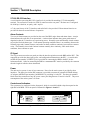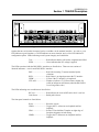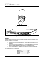
1
®
TRACER 2xT1
User’s Manual
TRACER 2xT1 User’s Manual
61280.003L2-1A
61280.003L2-1A
TRACER 2xT1 User’s Manual
RADIO FREQUENCY INTERFACE STATEMENT
This equipment has been tested and found to comply with the limits for an intentional radiator, pursuant
to Part 15, Subpart C of the FCC Rules. This equipment generates, uses, and can radiate radio frequency
energy. If not installed and used in accordance with the instructions, it may cause interference to radio
communications.
The limits are designed to provide reasonable protection against such interference in a residential
situation. However, there is no guarantee that interference will not occur in a particular installation. If
this equipment does cause interference to radio or television reception, which can be determined by
turning the equipment on and off, the user is encouraged to try to correct the interference by one or more
of the following measures:
•
•
•
•
Reorient or relocate the receiving antenna of the affected radio or television.
Increase the separation between the equipment and the affected receiver.
Connect the equipment and the affected receiver to power outlets on separate circuits.
Consult the dealer or an experienced radio/TV technician for help.
WARNING
Changes or modifications not expressly approved by ADTRAN could void the user’s authority to
operate the equipment.
Shielded Cables
A shielded-type power cord is required in order to meet FCC emission limits and also to prevent
interference with nearby radio and television reception when using the AC voltage adapter. It is essential
that only the Adtran-provided power cord be used.
FCC Output Power Restrictions
The FCC does not require licensing to implement this device. However, the FCC has established
restrictions regarding maximum output power and the adjustments required when employing directional
gain antennas. (Refer to “Setting the Transmitter Power” in Section 2 of this manual). These restrictions
are detailed in FCC Part 15.247 (b)(1), (b)(3)(i), and (3)(iii). It is the responsibility of the individuals
designing and implementing the radio system to assure compliance with these and any other pertinent
FCC Rules and Regulations. This device must be professionally installed.
Exposure to Radio Frequency Fields
This device is designed to provide a maximum power output of 100 mW. This level of RF energy in
itself is below the Maximum Permissible Exposure (MPE) levels specified in FCC OET 65:97-01. The
installation of high gain antenna equipment in the system configuration may create the opportunity for
exposure to levels higher than recommended for the general population at a distance less than one meter
from the center of the antenna. The following precautions must be taken during installation of this
equipment:
TRACER 2xT1 User’s Manual
i
61280003L2-1A
Radio Frequency Interference Statement
•
•
•
•
•
The installed antenna must not be located in a manner that allows exposure of the general
population to the direct beam path of the antenna at a distance less than one meter. Installation on
towers, masts, or rooftops not accessible to the general population is recommended; or
Mount the antenna in a manner that prevents any personnel from entering the area within one
meter from the front of the antenna
During antenna installation, be sure that power to the TRACER equipment is turned off in order to
prevent any energy presence on the coaxial connector.
During installation and alignment of the antenna, do not stand in front of the antenna assembly.
During installation and alignment of the antenna, do not handle or touch the front of the antenna.
These simple precautions must be taken to prevent general population and installation personnel from
exposure to RF energy in excess of specified MPE levels.
ii
TRACER 2xT1 User’s Manual
61280003L2-1A
Table of Contents
Page
Section 1 TRACER Description
Introduction ................................................................................................................................. 1
ISM Band Spread Spectrum ........................................................................................................ 1
NEBS ........................................................................................................................................... 1
Applications ................................................................................................................................. 2
Spread Spectrum .......................................................................................................................... 2
Direct Sequence ......................................................................................................... 2
Coding ....................................................................................................................... 2
Channel Selection ........................................................................................................................ 3
Forward Error Correction ............................................................................................................ 3
T1 Operation .............................................................................................................. 3
Framing ....................................................................................................... 3
Line Code ................................................................................................... 4
DS1/DSX-1 Interface ................................................................................. 4
Line Buildout or LBO ................................................................................ 4
TRACER System Configuration ................................................................................................. 4
Baseband Processor or BBP ...................................................................................... 4
DS1/DSX-1 Interface ................................................................................................ 5
VT-100 RS-232 Interface .......................................................................................... 6
Alarm Contacts .......................................................................................................... 6
IF Signal .................................................................................................................... 6
Power ......................................................................................................................... 6
Controls and Indicators .............................................................................................. 6
Non-Volatile Memory ............................................................................................... 8
Built-In Tests ............................................................................................................. 8
Radio Frequency Convertor or RFC .......................................................................... 8
Antenna .................................................................................................................... 10
TRACER 2xT1 User’s Manual
iii
61280003L2-1A
Table of Contents
Section 2 Installation
Radio Frequency Interference Statement .................................................................................. 11
Shielded Cables ......................................................................................................................... 11
FCC Output Power Restrictions ................................................................................................ 11
Exposure to Radio Frequency Fields ......................................................................................... 11
Unpack, Inspect ......................................................................................................................... 12
Rackmounted RFC Configuration ........................................................................... 12
Mastmounted RFC Configuration ........................................................................... 12
Installation ................................................................................................................................. 13
Location and Mounting ........................................................................................... 13
Power Requirements ................................................................................................ 13
Grounding ................................................................................................................ 13
DS1/DSX-1 Interface .............................................................................................. 14
Link Planning ............................................................................................................................ 15
Antenna Feedline Loss ............................................................................................ 15
Antenna Gain ........................................................................................................... 15
Path Loss ................................................................................................................. 16
Path Availability ...................................................................................................... 16
Setting the Transmitter Power ................................................................................................... 17
Setting the RFC Frequency Plan ............................................................................................... 17
Connecting the BBP and the RFC ............................................................................................. 19
Applying Power ......................................................................................................................... 19
Automatic BBP Frequency Plan ................................................................................................ 19
Spreading Code ......................................................................................................................... 19
Co-Locating Multiple 2.4 GHz Systems ................................................................................... 20
Antenna Alignment ................................................................................................................... 20
RF Low ...................................................................................................................................... 20
Remote BERT ........................................................................................................................... 21
iv
TRACER 2xT1 User’s Manual
61280003L2-1A
Table of Contents
Alarm Contacts .......................................................................................................................... 21
Section 3 Operation
VT-100 User Interface ............................................................................................................... 23
RS-232 Interface ........................................................................................................................ 23
Modem Connection ................................................................................................................... 23
Telemetry Byte Oriented Serial Interface .................................................................................. 23
RF Down System Status ............................................................................................................ 28
Cable Connections ..................................................................................................................... 28
Password .................................................................................................................................... 28
Main Menu Selections ............................................................................................................... 29
System Status Page .................................................................................................. 29
Main Menu Page ...................................................................................................... 31
T1 Status Page ......................................................................................................... 31
Link Performance History ....................................................................................... 31
Channel A Statistics Page ........................................................................................ 31
Channel B Statistics Page ........................................................................................ 32
Alarm Page .............................................................................................................. 32
Test Menu ................................................................................................................ 33
Configuration Menu ................................................................................................ 34
Remote Access .......................................................................................................................... 35
Section 4 Troubleshooting
General....................................................................................................................................... 37
Problem Descriptions and Recommended Actions ................................................................... 37
Troubleshooting using the front panel indicators .................................................... 37
“Link Error” light is lit, or link is down ................................................... 37
“BPV” light on T1-A or B is lit ................................................................ 38
RED light on T1-A or B is lit ................................................................... 38
TRACER 2xT1 User’s Manual
v
61280003L2-1A
Table of Contents
“LBK-A” or “LBK-B” is lit...................................................................... 39
“AIS/YEL” on T1-A or T1-B is lit ........................................................... 39
“AIS/YEL” indicator is flashing............................................................... 40
No “Power” light ...................................................................................... 40
“Test” light is lit or blinking ..................................................................... 41
“TST” light is lit after pressing “Remote Test button .............................. 41
“Fail” light is lit after pressing “Remote Test” button ............................. 42
“RF Low” light is on ................................................................................ 42
Troubleshooting Using the VT-100 User Interface ................................................. 43
RED Alarm ............................................................................................... 43
BLV Alarm ............................................................................................... 43
YEL/AIS Alarm ........................................................................................ 44
RF Link Alarm or Code Sync Alarm ....................................................... 44
Carrier Sync Alarm or T1 Mux Framer Alarm......................................... 45
ES Values in T1 Status Menu ................................................................... 46
SES Values in History Menu .................................................................... 46
Section 5 Specifications
Transmitter ................................................................................................................................ 47
Receiver ..................................................................................................................................... 47
Frequency Plan .......................................................................................................................... 47
Spread Spectrum Data Pump ..................................................................................................... 47
Interface Specifications ............................................................................................................. 57
User Interface ............................................................................................................................ 47
VT-100 Terminal Interface ........................................................................................................ 48
Mechanical & Environmental .................................................................................................... 48
Power ......................................................................................................................................... 48
vi
TRACER 2xT1 User’s Manual
61280003L2-1A
Table of Contents
Section 6 Warranty, Ordering and Return Information
Warranty .................................................................................................................................... 49
Sales ........................................................................................................................................... 49
Repairs and Returns ................................................................................................................... 49
Technical Support ...................................................................................................................... 49
Glossary
Acronyms Used in This Manual ................................................................................................ 51
Appendix A Cable Connections
Terminal Connection (DB25) .................................................................................................. A-1
Personal Computer Connection (DB9) .................................................................................... A-1
Modem Connection (DB25) .................................................................................................... A-2
TRACER 2xT1 User’s Manual
vii
61280003L2-1A
Table of Contents
Illustrations
1-1.
Typical Application ...................................................................................................... 2
1-2.
Bandwidth Division ...................................................................................................... 3
1-3.
BBP ............................................................................................................................... 4
1-4.
BBP Rear Panel ............................................................................................................ 5
1-5.
BBP Block Diagram ..................................................................................................... 5
1-6.
BBP Front Panel (with door closed) ............................................................................. 6
1-7.
BBP Front Panel (with door open) ............................................................................... 7
1-8.
RFC Module ................................................................................................................. 9
1-9.
RFC Function Block Diagram ...................................................................................... 9
1-10.
Mastmount RFC Housing ........................................................................................... 10
1-11.
Rackmount RFC Housing ........................................................................................... 10
2-1.
Diplexer ...................................................................................................................... 18
3-1.
Rear Panel Connectors................................................................................................ 24
3-2
System Status Page ..................................................................................................... 28
3-3
System Status Page ..................................................................................................... 29
3-4
Main Menu Page ......................................................................................................... 30
3-5.
T1 Status Page ............................................................................................................ 30
3-6.
Link Performance History Page ................................................................................. 31
3-7.
Channel A Statistics Page ........................................................................................... 31
3-8.
Channel B Statistics Page ........................................................................................... 31
3-9
Alarm Page ................................................................................................................. 32
3-10.
Test Menu ................................................................................................................... 33
3-11
T1 Loopback Locations .............................................................................................. 33
3-12.
Configuration Menu ................................................................................................... 34
3-13.
Remote Current System Status ................................................................................... 35
viii
TRACER 2xT1 User’s Manual
61280003L2-1A
SECTION 1
Section 1 TRACER
Description
TRACER
DESCRIPTION
INTRODUCTION
The TRACER provides dual T1 transport by way of a spread spectrum microwave link for distances up
to 30 miles or more depending on path engineering. System performance is determined, in part, by the
engineering of the microwave link. Each end of a TRACER link is composed of two units -- the
baseband processor (BBP) and the radio frequency converter (RFC). Two DS1/DSX-1 (T1) interfaces
are provided on the rear of the BBP, which can be mounted in a 19-inch rack. The DS1/DSX-1 interface
provides connections up to 6000 feet from T1 equipment. A single coaxial cable connects the BBP to the
RFC and another connects the RFC to the antenna.
ISM BAND SPREAD SPECTRUM
The Federal Communications Commission (FCC) has established several portions of the radio frequency
(RF) spectrum for use in Industrial, Scientific, and Medical (ISM) applications. Part 15.247 of the FCC
rules describes the requirements of systems that operate in these bands. The three bands set aside,
902-928 MHz, 2400-2483.5 MHz, and 5725-5850 MHz, are designated for use by spread spectrum
transmitters, either frequency hopping or direct sequence. The TRACER operates in the 2400 to 2483.5
MHz band using direct sequence spread spectrum (DSSS) transmission.
NEBS
Network Equipment Building Standards (NEBS) defines a rigid and extensive set of performance,
quality, environmental and safety requirements developed by Telcordia, the R&D and standards
organization owned by the seven regional Bell operating companies (RBOCs). NEBS compliance is
often required by telecommunications service providers such as BOCs (Bell Operating Companies) and
Interexchange Carriers (IEC) for equipment installed in their switching offices. NEBS defines everything
from fire spread and extinguish ability test to Zone-4 earthquake tests, thermal shock, cyclic temperature,
mechanical shock, and electro-static discharge. TRACER is NEBS Level 3 compliant (see Table 1-1
for a list of testing requirements.
Table 1-1. NEBS Testing Requirement
Document
GR-63 Operational Thermal
(Short Term Conditions)
Storage Environments and Transportation
and Handling
Earthquake (Zone 4 Level)
Airborne Contaminants (Outdoor Levels)
GR-1089 ESD (Installation and Repair)
EMI Emissions (Open Doors)
EMI Immunity (Open Doors)
Steady State Power Induction
Conditional Requirements
TRACER 2xT1 User’s Manual
Description
R4-6/72 Equip. should withstand exposure to “Table 4-4 Short T”
R4-7/73 Equip should withstand exposure to “Table 4-5 Short T”
R4-3 - R4-5/69-70 Exposure to tests in Tables 4-2, 4-3
R4-41- R4-43/107-109 Packaged and Unpackaged shock criteria
R4-58/124 Transportation vibration criteria
R4-44 - R4-46/110-112 Equipment and Frame Level testing of Section 5.4.1
R4-48/114 Functional requirements testing of Section 5.4.1
O4-49/115 Constructed to meet testing of Section 5.4.1
R4-51/117 Base mounting to floor without auxiliary support
R4-53/119 Specs for concrete anchors
O4-60/126 Equipment should withstand testing “Table 4-10”
R4-61/127 Equipment should withstand testing “Table 4-10” and o.s.air
O2-4/4 Perform under tests of IEC 801-2, Clause 5
O3-2/9 EMI Emissions (Open Doors)
CR3-11/18 Radiated Performance Criteria
R3-10/17 Radiated Immunity Criteria
CR5-2/43 Signaling - test to Table 5-1 (>20 ft)
CR5-4/45 C-Message -Signaling-test to test condition (>20 ft)
CR5-9/50 Signaling - test to Table 5-3 (>20 ft)
CR5-11/52 C-Message weighted metallic noise test (>20 ft)
1
61280003L2-1A
Section 1 TRACER Description
APPLICATIONS
Any application that would typically use metallic T1 as a transport can use the TRACER instead. Figure
1-1 illustrates a typical application.
Antenna
Antenna
RF Cable
Mast Unit
IF Cable
VT-100
RF Cable
TRACER
Baseband Processor
TRACER
Baseband Processor
RS-232
T1
POW
B
AIS
DATA
T1
B
AIS
DATA
TRACER
T1
TRANSCEI
POW
BP
AIS
DATA
T1
B
AIS
DATA
TRACER
TRANSCEI
Rack-mount RFC
TRACER
Terminal
T1
T1
T1
T1
Switch
Cell Radio
MSC
Cellular/PCS Site
2xT1, Mast-mounted RFC
2xT1, Rack-mounted RFC
Mast and Rack mount RFCs may be mixed to accommodate individual system requirements.
Figure 1-1. Typical Application
The TRACER can be used in any application requiring that data be shared at a high rate of speed. In
addition to telephony applications, TRACER can be used in data communications such as internetworking, video conferencing, and telemetry.
SPREAD SPECTRUM
Spread spectrum is a form of communication in which the bandwidth of a message signal is intentionally
increased or “spread.” The FCC rules allow two methods of spreading -- frequency hopping and direct
sequence. TRACER employs direct sequence spread spectrum.
Direct Sequence
A direct sequence transmitter spreads the signal by mixing the data with the output of a pseudorandom
number generator which changes state at a rate higher than the data rate. This rate is called the
“chipping” rate. The TRACER chipping rate is twelve times the data rate.
Coding
Many different pseudorandom sequences exist. The sequences are called pseudorandom because,
although they appear noise-like, they are determinant and repeat after a specific number of chips. The
longer a code is, the better correlation characteristics it possesses. These traits allow multiple spread
2
TRACER 2xT1 User’s Manual
61280003L2-1A
Section 1 TRACER Description
spectrum systems to operate in the presence of one another with minimal interference if they are
operating with different sequences. The TRACER allows the selection of one of ten different 120-bit
long sequences.
CHANNEL SELECTION
The FCC has allocated 83.5 MHz of spectrum in the band in which the TRACER operates. A TRACER
system fully uses the available bandwidth -- transmitting in one half and receiving in the other. Figure
1-2 illustrates the bandwidth division.
2441 MHz
2400 MHz
2483.5 MHz
Figure 1-2. Bandwidth Division
The transmitter at one end (TxA) of a link will transmit in the lower half of the spectrum. Consequently
the receiver at the other end will receive in the lower half of the band and transmit in the upper half.
Thus, a system will operate in one of two frequency plans -- transmit in the upper and receive in the
lower or vice versa. These two plans are called Plan A and Plan B. One end of a path will be on Plan A
and the other will be on Plan B. Shipment of a link will consist of an A and a B unless otherwise
specified.
FORWARD ERROR CORRECTION
With the addition of overhead data, error detection and correction capability can be added to a data
stream. Error correction can be accomplished by allowing the receiver to request the re-transmission of
an errored block once detected. The TRACER, on the other hand, implements forward error correction
(FEC) which adds enough overhead data for the receiver to detect and correct errors in the data stream.
This capability comes at the cost of bandwidth. The addition of FEC decreases the required signal-tonoise (S/N) ratio by approximately 5.5 dB to achieve a given bit error rate (BER).
T1 Operation
Framing
The data in a T1 stream is delimited by framing bits. The pattern of the framing bits follows one of two
formats -- extended superframe ( ESF) or superframe (SF). The T1 interface must be prepared for the
format that will be used.
TRACER 2xT1 User’s Manual
3
61280003L2-1A
Section 1 TRACER Description
Line Code
A mark in the data stream is coded as a pulse on the T1 line. A space is coded as “no activity” on the T1
line. As a form of error detection, subsequent marks in the data stream are coded as pulses of alternating
polarity, either positive going or negative going. This type of line coding is called alternate mark
inversion (AMI).
For the T1 receiver to operate correctly, a minimum number of “1s” must exist on the T1 facility. If the
data cannot be guaranteed to meet this requirement, then another line coding format is used. In the
bipolar 8 zero substitution (B8ZS) scheme, a string of eight “0s” is replaced by a special sequence of
eight bits that contains a bipolar violation. The receiver, upon recognizing this sequence, reinserts the
eight “0s” and the data is recovered intact.
DS1/DSX-1 Interface
When connecting the interface to the public switched network, an ADTRAN-provided cross-over cable
(part number 3125M011@A) is required to meet FCC part 68 and IC CS03 requirements. This cable is
required to cross-over the Tx and Rx pairs to meet the connecting arrangement of a network interface
device. This cable is included with the BBP and is labelled “T1 Crossover.”
Line Buildout or LBO
The DS1/DSX-1 interface provides two different types of line buildouts (LBOs), respectively. When set
for DS1, LBOs for 0 dB, -7.5 dB, -15 dB, and -22 dB are available. The DS1 interface can operate on
line lengths up to 6,000 feet. When set for DSX-1 interface, LBOs for 0-133 feet, 266-399 feet, 399-533
feet, and 533-655 feet are available.
TRACER SYSTEM CONFIGURATION
A TRACER system is composed of three major subsystems -- a baseband processor, a radio frequency
convertor, and an antenna. The following section describes the system components.
Baseband Processor or BBP
The BBP (ADTRAN part number 1280003L2) is a 1-U, 19-inch rackmountable unit that provides the
system electrical interfaces, user controls and indicators, and performs the spread spectrum processing
for the system. The rear panel provides all of the electrical interface points -- DS1/DSX-1 interface,
DS1/DSX-1 monitor, VT-100 terminal, alarm contacts, IF signal, DC power (from facility), and power
(from AC adapter). The BBP and its rear panel are illustrated in Figure 1-3 and 1-4.
T1A
BPV
T1B
BPV
FREQ
SYSTEM
TEST
LBK
LBK
PLAN A
RF LOW
POWER
YEL/AIS
YEL/AIS
PLAN B
LINK DOWN
RED
RED
Figure 1-3. BBP
4
TRACER 2xT1 User’s Manual
61280003L2-1A
Section 1 TRACER Description
MANAGEMENT
Figure 1-4. BBP Rear Panel
DS1/DSX-1 Interface
Two DS1/DSX-1 interfaces, labelled “T1A” and “T1B,” are provided for connecting to the T1
equipment. Two types of physical interfaces are provided -- RJ-48C and bantam jacks.
The interfaces are illustrated in Figure 1-5, BBP Block Diagram. The functions of the BBP are
partitioned into three printed circuit boards or PCBs, all contained in the same enclosure.
RS-232
UART
T1A
T1
Baseband Processor Board
µC
T1C
Multiplex
T1B
Spread
Spectrum
Data
Pump
Viterbi
Encoder/
Decoder
T1
Fc = 140 MHz
IF
Filter
Σ
DSP
90
Fc = 70 MHz
90
IF Interface Board
-48Vdc
Figure 1-5. BBP Block Diagram
The DS1/DSX-1 interfaces provided for each channel are the same. The upper bantam connectors,
labeled “Monitor,” provide isolated monitor points for testing. The lower bantam jacks provide signal
insertion points. The insertion of a bantam jack disconnects the RJ-48C connector from the circuit. The
DS1/DSX-1 interface can operate on line lengths up to 6000 feet.
When connecting either T1 interface to the public switched network, an ADTRAN-provided cross-over
cable (part number 3125M011@A) is required to meet FCC part 68 and IC CS03 requirements. This
cable is included with the BBP and is labelled “T1 Crossover.” This cable is required to cross-over the
TX and RX pairs to meet the connecting arrangement of a network interface device.
For connections to other CPE-type equipment, such as an ADTRAN TSU-100, a straight-through T1
cable is provided by ADTRAN (part number 3127004) and is included with the BBP.
TRACER 2xT1 User’s Manual
5
61280003L2-1A
Section 1 TRACER Description
VT-100 RS-232 Interface
A serial interface port using RS-232C signal levels is provided for attaching a VT-100-compatible
terminal. The connection is made via a DB-25 connector on the rear panel. The data rate is configured
for 9600 bps, 8 data bits, no parity, and 1 stop bit.
A 7-day error history of the T1 interfaces and radio link is also provided. Fifteen-minute histories are
provided for the most recent 24 hours of operation.
Alarm Contacts
Two sets of alarm contacts are provided on the rear of the BBP: major alarm and minor alarm. A major
alarm indicates the radio link is not operational. A minor alarm indicates that system performance is
degraded or that the T1 interfaces are experiencing errors. Normally-open and Normally-closed contacts
are provided for both alarm types. Under normal operating conditions there is no continuity between the
Normally-open and Common contacts, and, under an alarm condition, continuity between those contacts
exists. The Normally-closed and Common contacts normally have continuity, while under alarm
conditions, these contacts are open.
IF Signal
The N-type connector on the rear panel provides the interface point between the BBP and the RFC. This
connection provides the data signal, power, and configuration information to the RFC. A coaxial cable
(ADTRAN part number 3125RF027@A) is provided for connecting the BBP to the RFC for the
rackmount model. Cable for connecting the BBP to a mastmount RFC must be provided by the customer
after the length of cable has been determined.
Power
The unit receives power via one of two connectors. Power for the entire system is provided by these
interfaces. The three-pin circular DIN connector is provided to connect an optional ADTRAN desktop
AC adapter (ADTRAN part number 1360DSK24VL1), providing 24 volts DC. The three-pin terminal
block allows the connection of any DC power source providing between 21 and 60 volts DC. The power
consumption of the entire system is 30 watts.
Controls and Indicators
The system may be configured via the front panel, which is accessible behind a drop-down panel on the
right half of the BBP. The front panel is illustrated in Figures 1-6 and 1-7.
T1A
TEST
POWER
BPV
LBK
YEL/AIS
RED
T1B
BPV
LBK
YEL/AIS
RED
FREQ
SYSTEM
PLAN A
RF LOW
PLAN B
LINK DOWN
Figure 1-6. BBP Front Panel (with door closed)
6
TRACER 2xT1 User’s Manual
61280003L2-1A
Section 1 TRACER Description
UP
DOWN
Figure 1-7. BBP Front Panel (with door open)
Options that are set from the front panel can be overridden via the terminal interface. As a rule, a green
LED indicates a good situation, a red LED indicates an error situation, and a yellow LED indicates a
configuration option. LEDs indicating overall system integrity are listed below.
Test ............................... Red indicates that the self-test has completed and failed
PWR ............................. Green indicates that DC voltage is applied
The LEDs associated with the DS1/DSX-1 interfaces are listed below. There are two sections of
identical indicators -- one for each DS1/DSX-1 interface.
BPV .............................. Red if the incoming T1 stream contains bipolar
violations
RED .............................. Red if there is no signal present at the T1 interface
LPBK ............................ Yellow if the T1 interface is in loopback
YEL/AIS ...................... Flashes to indicate a T1 Yellow Alarm; remains On
(solid) to indicate an AIS alarm (when the DS1/DSX-1
is receiving a Blue code)
The LEDs indicating error conditions are listed below.
RF Low ......................... Red indicates the received RF carrier level is too low
Link Down ................... Radio path is down
The front panel controls are listed below.
Reset ............................. Reset the system
LBKA ........................... Toggles the T1-A between no loopback and line
loopback
LBO .............................. Selects TI line buildout. Template on right edge of
faceplate designates switch setting.
LBKB ........................... Toggles the T1-B between no loopback and line
loopback
TRACER 2xT1 User’s Manual
7
61280003L2-1A
Section 1 TRACER Description
Tx PWR ........................ UP increments radio transmit power up.
DOWN increments radio transmit power down.
VT100 terminal will indicate Tx Power setting.
Remote Test ................. Initiate a remote test across the RF link
Non-volatile Memory
The TRACER system contains non-volatile memory to retain certain configuration settings. These
settings include:
Frequency plan
Chipping code (if set from VT-100)
Password
Password enabling
Site name
T1 line coding (if set from VT-100)
T1 framing (if set from VT-100)
Built-In Tests
The TRACER has several features to aid in site setup and later debugging. These diagnostics include T1
loopbacks and a link test with BERT (Bit Error Rate Test) data. A link test is performed by pressing the
test button. The remote unit will then send a pseudorandom data pattern and the local end will compute a
BER. After the conclusion of the test, the remote end will automatically be instructed to terminate the
pattern generation. If any bit errors are introduced, the Remote Test Fail LED will illuminate.
The monitor points provided on the front panel of the system are listed on the next page.
I ......................................Demodulated received baseband output
Q ....................................Demodulated received baseband output
CLK ...............................Recovered clock for observing EYE pattern
RSSI ..............................DC voltage indicating strength of the received signal at
the antenna
+5 ...................................System 5 volts
-5 ....................................System -5 volts
+12 .................................System +12 volts
-12 .................................System -12 volts
RF PWR ........................Voltage supplying RF power
GND ..............................System ground
Radio Frequency Converter or RFC
The radio frequency converter (RFC) provides the radio frequency (RF) interface between the baseband
processor and the antenna. The RFC is partitioned, functionally, into two major components - the
transmitter and the receiver.
The major connections illustrated in Figure 1-8 are transmit signal, receive signal, and the IF signal
connection.
The RFC unit is enclosed in a metal enclosure approximately 10.5 inches x 5.5 inches x 1 inch and is
mounted in a 1-U, 19-inch rackmountable housing or mastmountable, weatherproof enclosure.
8
TRACER 2xT1 User’s Manual
61280003L2-1A
Section 1 TRACER Description
RSSI
GND TX-PW
R
RX
IF
TX
Figure 1-8. RFC Module
Three SMA connectors, located on the RFC module, provide RF and IF connection points. A test point is
provided for monitoring the received signal strength indicator (RSSI). The voltage (relative to the GND
test point) present on this test point represents the level of the received signal. This signal is used to align
the antenna when installing the system and to verify the link is performing as designed. Another test
point is provided to monitor the transmitter output power during system configuration. The only
connections that must be made in the field are a coax connection between the baseband processor and the
RFC and a coax connection between the RFC and the antenna. These connections require male, type N
coax connectors.
The IF connector provides the connection between the baseband processor and the rackmounted or
mastmounted RFC. (An 8-inch IF cable [ADTRAN part # 3125RF027@A] is provided for rackmount
systems). The TO ANTENNA connection provides the connection between the RFC and the antenna. A
block diagram of the RFC functions is show in Figure 1-9.
The RFC module is enclosed in either a 19-inch EIA rackmount housing, or a weather-tight enclosure
suitable for mastmounting near the antenna for enhanced system performance. The RFC mastmount and
rackmount housings are illustrated in Figures 1-10 and 1-11.
Rx
SAW
2018
2058
Splitter
LPF
333
AGC
IF
Tx
PA
Splitter
2321
2281
AGC
RF2
Figure 1-9. RFC Function Block Diagram
TRACER 2xT1 User’s Manual
9
61280003L2-1A
Section 1 TRACER Description
Figure 1-10. Mastmount RFC Housing
Figure 1-11. Rackmount RFC Housing
Antenna
TRACER is intended to be coupled with an antenna that is directional and provides signal gain. There
are several reasons for this requirement:
•
•
•
TRACER operates in point-to-point applications; therefore, an omnidirectional antenna is
not needed.
The FCC provides no recourse in this band in the event of nearby interference, so a highly
directional antenna reduces the likelihood of interference in the antenna pattern.
The low power transmitter is intended to be used with a high-gain antenna for long links.
The antenna requirements are listed below.
Minimum gain ............................. 15 dBi
Minimum return loss ................... 15 dB
Connector .................................... N-type
Impedance ................................... 50Ω
10
TRACER 2xT1 User’s Manual
SECTION 2
INSTALLATION
RADIO FREQUENCY INTERFERENCE STATEMENT
This equipment has been tested and found to comply with the limits for an intentional radiator, pursuant
to Part 15, Subpart C of the FCC Rules. This equipment generates, uses, and can radiate radio frequency
energy. If not installed and used in accordance with the instructions, it may cause interference to radio
communications.
The limits are designed to provide reasonable protection against such interference in a residential
situation. However, there is no guarantee that interference will not occur in a particular installation. If
this equipment does cause interference to radio or television reception, which can be determined by
turning the equipment on and off, the user is encouraged to try to correct the interference by one or more
of the following measures:
•
•
•
•
Reorient or relocate the receiving antenna of the affected radio or television.
Increase the separation between the equipment and the affected receiver.
Connect the equipment and the affected receiver to power outlets on separate circuits.
Consult the dealer or an experienced radio/TV technician for help.
WARNING
Changes or modifications not expressly approved by ADTRAN could void the user’s authority to
operate the equipment.
SHIELDED CABLES
A shielded-type power cord is required in order to meet FCC emission limits and also to prevent
interference with nearby radio and television reception when using the AC voltage adapter. It is essential
that only the ADTRAN-provided power cord be used.
FCC OUTPUT POWER RESTRICTIONS
The FCC does not require licensing to implement this device. However, the FCC has established
restrictions regarding maximum output power and the adjustments required when employing directional
gain antennas. (Refer to “Setting the Transmitter Power” in Section 2 of this manual). These restrictions
are detailed in FCC Part 15.247 (b)(1), (b)(3)(i), and (3)(iii). It is the responsibility of the individuals
designing and implementing the radio system to assure compliance with these and any other pertinent
FCC Rules and Regulations. This device must be professionally installed.
EXPOSURE TO RADIO FREQUENCY FIELDS
This device is designed to provide a maximum power output of 100 mW. This level of RF energy in
itself is below the Maximum Permissible Exposure (MPE) levels specified in FCC OET 65:97-01. The
installation of high gain antenna equipment in the system configuration may create the opportunity for
exposure to levels higher than recommended for the general population at a distance less than one meter
from the center of the antenna. The following precautions must be taken during installation of this
equipment:
TRACER 2xT1 User’s Manual
11
61280003L2-1A
Section 2 Installation
•
•
•
•
•
The installed antenna must not be located in a manner that allows exposure of the general
population to the direct beam path of the antenna at a distance less than one meter.
Installation on towers, masts, or rooftops not accessible to the general population is
recommended; or
Mount the antenna in a manner that prevents any personnel from entering the area within
one meter from the front of the antenna
During antenna installation, be sure that power to the TRACER equipment is turned off in
order to prevent any energy presence on the coaxial connector.
During installation and alignment of the antenna, do not stand in front of the antenna
assembly.
During installation and alignment of the antenna, do not handle or touch the front of the
antenna.
These simple precautions must be taken to prevent general population and installation personnel from
exposure to RF energy in excess of specified MPE levels.
UNPACK, INSPECT
Carefully inspect the TRACER for any shipping damages. If damage is suspected, file a claim
immediately with the carrier then contact ADTRAN Customer Service. If possible, keep the original
shipping container for use in shipping the TRACER back for repair or for verification of damage during
shipment.
Before beginning installation, verify that all of the following components are present.
Rackmounted RFC configuration:
Provided by ADTRAN
•
•
•
•
Baseband processor
Rackmounted RFC
BBP to RFC IF interconnect cable
DS1/DSX-1 interface cables (RJ-48 to RJ-48)
Provided by customer
•
•
•
•
Antenna feedline cable
Antenna and mounting hardware
VT-100 terminal and RS-232 interface cable (optional)
21 to 60 volt DC power source (available from ADTRAN),
either polarity referenced to ground
Mastmounted RFC configuration:
Provided by ADTRAN
Provided by customer
12
• Baseband processor
• Mastmounted RFC
• DS1/DSX-1 interface cables (RJ-48 to RJ-48)
•
•
•
•
•
Antenna feedline cable
Antenna and mounting hardware
BBP to mastmounted RFC IF interconnect cable
VT-100 terminal and RS-232 interface cable (optional)
21 to 60 volt DC power source (available from ADTRAN),
either polarity referenced to ground
TRACER 2xT1 User’s Manual
61280003L2-1A
Section 2 Installation
INSTALLATION
Location and Mounting
Install the TRACER in a location that requires minimal antenna feedline length (the loss in this cable
directly affects overall system performance). The BBP is designed to be mounted in a rack, above the
RFC. Although no space is needed between the units, certain regulations may require at least .75" of
space above and below the BBP.
Power Requirements
The TRACER can operate from a supply between 21 and 60 volts DC, with either polarity referenced to
ground, and consumes 30 watts. Amperage is determined by dividing the wattage (30) by the input
voltage (i.e., 30 watts/48 volts = .625 amps),
Grounding
The following grounding instructions are derived from the Underwriters’ Laboratory UL 1459 Standard
for Safety: Telephone Equipment dated September 20, 1993.
An equipment grounding conductor that is no smaller in size than the ungrounded branch-circuit supply
conductors is to be installed as part of the circuit that supplies the product or system. Bare, covered, or
insulated grounding conductors are acceptable. Individually covered or insulated equipment grounding
conductors shall have a continuous outer finish that is either green, or green with one or more yellow
stripes. The equipment grounding conductor is to be connected to ground at the service equipment.
The attachment-plug receptacles in the vicinity of the product or system are all to be of a grounding type,
and the equipment grounding conductors serving these receptacles are to be connected to earth ground
at the service equipment.
A supplementary equipment grounding conductor shall be installed between the product or system and
ground that is in addition to the equipment grounding conductor in the power supply cord.
The supplementary equipment grounding conductor shall not be smaller in size than the undergrounded
branch-circuit supply conductors. The supplementary equipment grounding conductor shall be
connected to the product at the terminal provided, and shall be connected to ground in a manner that
will retain the ground connection when the product is unplugged from the receptacle. The connection to
ground of the supplementary equipment grounding conductor shall be in compliance with the rules for
terminating bonding jumpers at Part K or Article 250 of the National Electrical Code, ANSI/NFPA 70.
Termination of the supplementary equipment grounding conductor is permitted to be made to building
steel, to a metal electrical raceway system, or to any grounded item that is permanently and reliably
connected to the electrical service equipment ground.
Bare, covered, or insulated grounding conductors are acceptable. A covered or insulated grounding
conductor shall have a continuous outer finish that is either green, or green with one or more yellow
stripes.
The supplemental equipment grounding terminals are located on the rear of the BBP adjacent to the
power connectors and on the rear of the rackmounted RFC.
TRACER 2xT1 User’s Manual
13
61280003L2-1A
Section 2 Installation
DS1/DSX-1 Interface
The rear panel of the TRACER has two sets of jacks labeled T1A and T1B which provide the same
functionality. The pin assignments for the eight-position modular jack are listed below.
Pin
Name
Function
1 ................ R ....................... Send data (ring)
2 ................ T ....................... Send data (tip)
3 ........................................... Not used
4 ................ R1 ..................... Receive data (ring)
5 ................ T1 ..................... Receive data (tip)
6 ........................................... Not used
7 ........................................... Not used
8 ........................................... Not used
Bantam jack connections are provided for test equipment access. Data is received on the jack labelled
“IN” and is transmitted on the jack labelled “OUT.” Bantam jacks are provided for both inserting and
monitoring the interfaces. When a plug is placed in the insert jack, the connection between the modular
jack and the interface circuitry is broken. The monitor jacks provide access to monitor the transmitted
and received signals without interference.
When connecting either T1 interface to the public switched network, an ADTRAN-provided crossover
cable (part number 3125M011@A) is required to meet FCC part 68 and IC CS03 requirements. This
cable is required to cross-over the Tx and Rx pairs to meet the connecting arrangement of a network
interface device. This cable, labelled “T1 Crossover,” is included with the BBP.
For connections to other CPE-type equipment, such as an ADTRAN TSU, a straight-through T1 cable
(ADTRAN part number 3127004) is included with the BBP.
Each DS1/DSX-1 interface must be configured for line code and framing, either from the front-panel
rocker switches or via the VT-100 terminal. The choices for line code are AMI and B8ZS. The options
for framing are SF and ESF. Each channel can be configured independently of the other and should be
configured to match the attached T1 equipment.
The line build-out (LBO) must be set for each DS1/DSX-1 interface. The LBO setting allows each
DS1/DSX-1 interface transmitter to drive the interface with the correct signal strength based on the line
attenuation between TRACER and the attached equipment. The LBO is independently set for each
interface via rotary switches on the front panel. Two sets of configurations are provided -- DSX-1 for
short-haul interface (less than 655 feet) and DS1 for long-haul interfaces (greater than 655 feet). The
settings are detailed below.
Interface Type
LBO
Switch Setting
DSX-1 .......................... 0-133 feet ................... 2, 3
DSX-1 ........................ 133-266 feet ................... 4
DSX-1 ............................ 266-399 ....................... 5
DSX-1 ............................ 399-533 ....................... 6
DSX-1 ........................ 533-655 feet ................... 7
DS1 .................................... 0 dB .......................... 8
DS1 ................................. -7.5 dB ........................ 9
DS1 .................................. -15 dB ....................... 10
DS1 ................................ -22.5 dB ...................... 11
14
TRACER 2xT1 User’s Manual
61280003L2-1A
Section 2 Installation
LINK PLANNING
IMPORTANT
The appropriate transmitter power must be calculated as part of the link planning.
The factors that must be taken into account when planning a link are optimal received signal level,
transmitter power, antenna feedline loss (each end), antenna gain (each end), free space path loss, and
required fade margin.
IMPORTANT
The optimal signal level for the receiver is -60 dBm.
Antenna Feedline Loss
Feedline loss is a function of feedline type and length. Feedline loss per 100 feet for several types of
coax at IF and RF frequencies is detailed in the table below. The IF loss applies to BBP/RFC
interconnection, and the RF loss applies to RFC/antenna interconnection. Antenna manufacturers’
specifications may vary.
IF Loss/100 feet
RF Loss/100 feet
Cable
(in dB)
(in dB)
RG58 .......................... 5.7 .................................... 80
RG8 (air) .................... 2.7 .................................... 20
RG8 (foam) .................. 2 ...................................... 9
1
/4" Waveguide .......... 1.42 .................................. 5.91
3
/8" Waveguide .......... 1.25 .................................. 5.76
1
/2" Waveguide .......... 0.81 .................................. 3.83
7
/8" Waveguide .......... 0.44 ................................... 2.2
1 1/4" Waveguide ....... 0.33 .................................. 1.62
1 5/8" Waveguide ....... 0.27 .................................. 1.41
Antenna Gain
Best performance will result from the use of a parabolic dish antenna. Antenna gain is determined by the
size of the dish, with typical figures detailed below. Dish manufacturers will be able to supply gains for
other types of antenna.
Dish Diameter
(in feet)
2
4
6
8
10
12
TRACER 2xT1 User’s Manual
Gain
(in dBi)
21
27
31
33
35
37
15
61280003L2-1A
Section 2 Installation
Path Loss
The free space path loss is given by
Loss(dB) = 96.6 + 20 log10f + 20log10D
where D is distance in miles
f is operating frequency in GHz
A tabulation of various path loss is given below.
Link Distance
Path Loss
(in miles)
(in dB)
1 ................................ 104
2 ................................ 110
3 ................................ 114
4 ................................ 116
5 ................................ 118
6 ................................ 120
7 ................................ 121
8 ................................ 122
9 ................................ 123
10 ............................... 124
11 ............................... 125
12 ............................... 126
Link Distance
Path Loss
(in miles)
(in dB)
13 ............................... 126
14 ............................... 127
15 ............................... 128
16 ............................... 128
17 ............................... 129
18 ............................... 129
19 ............................... 129
20 ............................... 130
21 ............................... 130
22 ............................... 131
23 ............................... 131
24 ............................... 132
Path Availability
The availability of a path can be expressed by:
availability = (1 - C x T x 2.5 x 10⁻⁶ x f x D3 x 10-F/10) x 100%
where C is the climate factor
T is the terrain factor
f is the frequency in GHz
D is the path length in miles
F is the fade margin in dB
Climate factors are given below.
Climate
Climate
Factor
Very Dry ............ 1/8
Temperate .......... 1/4
Humid ................ 1/2
16
TRACER 2xT1 User’s Manual
61280003L2-1A
Section 2 Installation
Terrain factors are listed below
Terrain
Terrain
Factor
Smooth ............................................................... 4
Average .............................................................. 1
Mountainous ..................................................... 1/4
The nominal received signal level is -60 dBm. For help in link planning, use the path loss calculation
worksheet below.
- 91 dBm .............................................. Minimum Signal Power
+ _______ ............................................. Transmitter Feedline Loss
- _______ ............................................. Transmitter Antenna Gain
+ _______ ............................................ Path Loss
- _______ ............................................. Receiver Antenna Gain
+ _______ ............................................ Receiver Feedline Loss
+ _______ ............................................ Required Fade Margin
= _______ ............................................ (dBm) Transmitter Power Setting
SETTING THE TRANSMITTER POWER
The FCC specifies the maximum transmitter power that may be used for antennae of a given gain. FCC
rules Part 15, Subpart 247 allow for a maximum power of 1 watt into antennae of a gain less than or
equal to 6 dBi. For every 3 dB of gain over 6 dBi, the transmitter must be reduced by 1 dB. The
following table lists the maximum transmitter power for given antennae gains.
Antenna
Gain
Power
6 dBi ......................................... 30 dBm
12 dBi ....................................... 28 dBm
18 dBi ....................................... 26 dBm
24 dBi ....................................... 24 dBm
30 dBi ....................................... 22 dBm
36 dBi ....................................... 20 dBm (TRACER’s maximum power output)
The transmitter power is set by way of a potentiometer on the front panel of the BBP or via the
configuration page of the interface VT-100. The RFC must be attached by way of the IF cable during
this operation. Attach an RF power meter to the N-type antenna connector on the RFC, and adjust the
power by way of the potentiometer or VT-100 until the desired transmitter power is obtained. For
convenience, the transmitter power adjustment should be made before the RFC is installed on the mast.
SETTING THE RFC FREQUENCY PLAN
The frequency plan designates on which frequencies the TRACER transmits and receives. Plan A
corresponds to a transmitting (Tx) frequency of 2422 MHz and a receive (Rx) frequency of 2462 MHz.
Plan B corresponds to a Tx frequency of 2462 MHz and a Rx frequency of 2422 MHz. Shipment of a
link consists of one RFC set to Plan A and the other set to Plan B unless specified otherwise. The RFC
plan can, however, be changed in the field if required. This procedure involves configuring the RFC
interconnect cables.
TRACER 2xT1 User’s Manual
17
61280003L2-1A
Section 2 Installation
For rackmounted systems, do the following to reconfigure the RFC interconnect:
Remove the four screws which retain the RFC cover and remove the cover.
The RF unit may be identified by following the connection from the port labelled “IF” on the
rear of the RFC. This connection terminates at the RF unit. The diplexer may be identified
by following the connection from the “Antenna” port on the rear of the RFC. This
connection terminates at the diplexer, illustrated in the Figure 2-1.
2421
Anten
PLAN
na
A
2462
1.
2.
Figure 2-1. Diplexer
3.
4.
5.
6.
7.
8.
9.
Unscrew the cable assemblies from the ports labelled “Tx” and “Rx” on the RFC, and the
ports labelled “2422” and “2462” (or “J1” and “J2” on some models) on the diplexer,
depending on the frequency Plan (Plan A or Plan B).
Unscrew the cable assembly from the port labelled “Antenna” on the diplexer.
Remove the four screws from the bottom of the RFC that hold the diplexer in place.
Turn the diplexer over revealing the opposite frequency plan (from Plan A to Plan B, or vice
versa).
Realign the diplexer with the screw holes and replace the four screws that attach it to the
bottom of the RFC.
Reattach the loose cable assembly (from step 4) to the port labelled “Antenna” on the
diplexer.
Reattach the cable assemblies from the ports labelled “Tx” and “Rx” on the RFC, and the
ports labelled “2422” and “2462” (or “J1” and “J2” on some models) on the diplexer. Cable
connections should be aligned to each other as follows.
Plan A
Tx = 2422
Rx = 2462
Plan B
Tx = 2462
Rx = 2422
10. Replace and secure the RFC cover.
18
TRACER 2xT1 User’s Manual
61280003L2-1A
Section 2 Installation
For mastmounted systems, do the following to reconfigure the RFC interconnect:
1.
2.
3.
4.
5.
Remove the lid of the mast RFC.
Disconnect the three cables attached to the diplexer. The diplexer may be identified by
following the antenna connector to the middle connector of the diplexer. Leave the cables in
the same positions.
Remove the two screws securing the diplexer and rotate the diplexer to reveal the opposite
frequency plan label.
Reinstall the two screws and reattach the cables in the same positions.
Reinstall the lid of the mast RFC.
CONNECTING THE BBP AND THE RFC
The BBP and the RFC are connected by an IF cable, either supplied by ADTRAN (for rackmount
assembly) or by the customer (for mastmount assembly). This single connection provides everything the
RFC requires. The cable assembly attaches to the ports labeled “IF” on the BBP and the RFC.
APPLYING POWER
If the ADTRAN supplied tabletop power source is used, simply plug it into the circular receptacle
located in the “DC Power” area on the rear of the BBP. If a source of 21 to 60 volts DC (30 watts),
either polarity referenced to ground, is available, it may be attached to the terminal block located on the
rear of the BBP. The positive lead should be attached to the “+” side of the block and the negative lead
should be attached to the “-” side of the block.
CAUTION
Power sources must not be attached to both the circular connector and the terminal blocks at
the same time or damage will occur.
AUTOMATIC BBP FREQUENCY PLAN
Upon the initial application of power, the BBP will default to the factory-preset Frequency Plan, or to the
Frequency Plan determined by the cable configuration of the RFC. The LED will indicate which
frequency plan is active. On subsequent reboots, such as after a loss of power, the BBP will default to
the most recently used Plan setting.
SPREADING CODE
The spreading code for each end must be the same. The choice of operating code is selectable by the
operator or the installer. TRACER is shipped in a matched (default) configuration.
WARNING
It is possible for the spreading code to be changed remotely through the VT-100 interface from
the other end of the link. When this is performed, communications will be lost to the far end.
The spreading code will change to code “0” and communications will be lost as soon as this
change is made. If this happens, set the Spreading Code on the local unit to code “0”. The units
should regain communications as soon as the correct code is selected.
TRACER 2xT1 User’s Manual
19
61280003L2-1A
Section 2 Installation
CO-LOCATING MULTIPLE 2.4 GHz SYSTEMS
When multiple 2.4 GHz transmitters are to be co-located (installed in the same equipment room or on the
same tower), it is advised to set all systems as follows:
1.
2.
3.
If more than one 2.4 GHz system is transmitting from the same location, set the antenna
polarity of one system horizontal and the other system(s) vertical. (The antennas should be
marked as to which mounting position is vertical or horizontal.) This will provide
approximately 30 dB of isolation between the different antennas.
If more than one TRACER system is installed, set the co-located transmitters to the same
frequency plan (example: Plan A, Tx=2422; or Plan B, Tx=2462) and set each to a different
spreading code. This keeps the transmitters on the additional system(s) from interfering with
the co-located receiver(s).
If the systems are from different manufacturers, set the transmit frequencies as close as
possible with different spreading codes. Other manufacturers may not use the exact
frequency plans as the TRACER system, but keeping the frequencies close will reduce the
probability of the transmitter(s) interfering with the co-located receiver(s).
This equipment is authorized under CFR 47 Part 15.247. With this authorization by the FCC, this
equipment shall not be co-located with a similar transmitter that transmits identical information.
ANTENNA ALIGNMENT
After the transmitter power for each end has been adjusted and the BBP and RFC have been installed and
connected, the antenna should be connected to the RFC via the feedline. Verify that both antennas are
arranged on the same polarity: vertical or horizontal. The antennas should be aimed toward one another
as precisely as possible and the received signal strength indicator (RSSI) voltage measured. The RSSI
voltage is a function of the signal strength at the receiver and is used to measure the received signal
strength. RSSI varies approximately from 0 to 4 volts, with 0 volts corresponding to a weaker received
signal and 4 volts corresponding to a stronger received signal.
RF LOW
The “RF Low” LED indicates that the received signal is within 10dB of the minimum received signal
strength (~-80 dBm). If this indicator is on, the link performance may be marginal. The antennas should
be peaked in azimuth and elevation until the desired signal level is achieved. RSSI may be monitored on
either the RF unit or the front of the BBP. If the received signal is too strong and RSSI reaches a
maximum such that the peak cannot be discerned, then the transmitter on the far end should be turned
down.
At this point the radio link should be operational. Proper operation can be determined by the status of
the “LINK DOWN” LED. If this LED is on, the link is not operational. If this LED is not on, the link is
operating. Certain types of interference can cause one end of a path to operate and the other end to fail.
In some instances, this may be corrected by swapping the frequency plan at each end, thus avoiding the
interference if it is stronger at one end than the other. Changing the spreading code at each end may also
allow interference to be mitigated.
20
TRACER 2xT1 User’s Manual
61280003L2-1A
Section 2 Installation
REMOTE BERT
The TRACER includes a Bit Error Rate Tester (BERT) to verify that the installed system is operating
correctly. When the “Remote Test” button is pushed on the local BBP, the remote end will send a BERT
pattern for approximately 10 seconds. The “Remote TST” indicator will turn yellow and remain on for
the duration of the test. If no bit errors are detected, the “Remote TST” indicator will turn off. If any bit
errors are detected, the “Remote Fail” indicator will turn red. This test should be run after the radio link
has been aligned. If the test fails, refer to Section 4, “Troubleshooting,” for guidance.
ALARM CONTACTS
Two sets of alarm contacts are provided on the rear of the BBP: major alarm and minor alarm. A major
alarm indicates the radio link is not operational. A minor alarm indicates that system performance is
degraded or that the T1 interfaces are experiencing errors. Normally-open and Normally-closed contacts
are provided for both alarm types. Under normal operating conditions there is no continuity between the
Normally-open and Common contacts and under an alarm condition continuity between those contacts
exists. The Normally-closed and Common contacts normally have continuity, while under alarm
conditions, these contacts are open.
TRACER 2xT1 User’s Manual
21
61280003L2-1A
Section 2 Installation
22
TRACER 2xT1 User’s Manual
SECTION 3
OPERATION
VT-100 USER INTERFACE
The TRACER may be accessed with a VT-100 compatible terminal set to 9600 bits per second, 8 data
bits, and no parity, connected to the RS-232 port on the back of the unit. Once a terminal is connected,
pressing the ESC key will present the System Status screen. If password access has been enabled, then
press “Enter” or “Return” in order to see the “Enter Password:” message. TRACER is shipped with
password protection disabled.
RS-232 INTERFACE
The TRACER has an RS-232 interface for system management via an attached VT-100 terminal,
personal computer, or modem. The RS-232 port is configured as a DCE with the following pin
assignments:
Signal
Name
TXD
RXD
RTS
CTS
DSR
Ground
DCD
DTR
Pin
Number
2
3
4
5
6
7
8
20
Direction
To TRACER
From TRACER
To TRACER
From TRACER
From TRACER
To TRACER
To TRACER
MODEM CONNECTION
Option 16, discussed in the Configuration Menu page of this section, will enable or disable modem
control. When this option is enabled from a standard terminal connection, all RS-232 communications
will cease until a modem is attached with a Null-Modem adapter between the TRACER and data modem.
The data modem will need to be configured for AUTO ANSWER and 9600 BPS. When the user
connects via modem to the TRACER unit, communications via the RS-232 port will resume. If a user
accidentally enables modem control from a terminal and disrupts the RS-232 communication, pressing
[CTRL Z] three times, will temporarily disable the modem control option. This will allow the user to
access the configuration menu to disable modem control.
When modem control is enabled, the RS-232 port is inactive until DTR and DCD are active. This
prohibits data being sent to the modem or received from the modem while idle. The required NullModem adapter may be obtained at any computer hardware supplier. A straight-through serial cable
should be used between the adapter and the modem or TRACER unit. To ensure that the far-end modem
disconnects when desired, option 17 of the CONFIGURATION MENU will disconnect the modem. The
modem must be configured to drop the connection on loss of DTR in order to disconnect.
TELEMETRY BYTE ORIENTED SERIAL (TBOS) INTERFACE
E-telemetry systems were developed by the pre-divestiture AT&T organization as a method to monitor
and control diverse network elements from a remote, centralized location. Status and command remote
(SAC) units were employed in the central office to convert discrete (contact closure) alarms from
monitored equipment into E-telemetry for efficient transfer of data to and from the operations center.
TRACER 2xT1 User’s Manual
23
61280003L2-1A
Section 3 Operation
With the advent of microprocessor technology, the alarm processing remote (APR, alarm remote or
simply Remote) was developed, allowing discrete alarm links with network elements to be supplanted by
a more efficient serial link. TBOS is the communications protocol defined for this link.
The TRACER rear panel designates the TBOS ports as “MANAGEMENT IN” (on the bottom) and
“MANAGEMENT OUT” (on the top). The TBOS polling station is connected to the MANAGEMENT
IN port. If several devices or TRACER systems are daisy-chained together, plug the TBOS manager into
the first units MANAGEMENT IN port (that physical unit does not have to be assigned TBOS address
#1), and then connect that units MANAGEMENT OUT to the next units MANAGEMENT IN port.
Follow that routine down the line, up to 8 units.
TBOS operates via RS422, therefore the inputs and outputs are differential pairs. The pinout for the
MANAGEMENT IN port is:
pin 1 - Transmit- (out of TRACER)
pin 3 - Transmit+ (out of TRACER)
pin 5 - Receive- (in to TRACER)
pin 7 - Receive+ (in to TRACER)
The pinout for the MANAGEMENT OUT port is:
pin 1 - Receive- (in to TRACER)
pin 3 - Receive+ (in to TRACER)
pin 5 - Transmit- (out of TRACER)
pin 7 - Transmit+ (out of TRACER)
The rear panel connectors are on a double-stack RJ45, so the pin numbers are opposite of each other:
A TBOS monitoring system will need to define the following bitmaps to indicate status and alarm
conditions.
PIN 8
PIN 1
_______
|
|
______|
|______
|
|
|
| MANAGEMENT OUT
|
|
|
| (TOP CONNECTOR)
|
|
|_|_|_|_|_|_|_|_|_| PIN 1
___________________
|_|_|_|_|_|_|_|_|_| PIN 8
|
|
|
| MANAGEMENT IN
|
|
|
| (BOTTOM CONNECTOR)
|_____
______|
|
|
|____|
Figure 3-1. Rear Panel Connectors
24
TRACER 2xT1 User’s Manual
61280003L2-1A
Section 3 Operation
A TBOS monitoring system will need to define the following bitmaps to indicate status and alarm
conditions.
Table 3-1. TRACER TBOS Alarm and Status Map
Char. / Point
Type
Scan Point Definition
Description
1/1
1/2
1/3
1/4
1/5
1/6
1/7
1/8
Status
Status
Status
Status
Status
Status
Status
Status
Frequency Plan
10 Second BERT Test
Local T1A Line Loopback
Local T1B Line Loopback
Local T1A Link Loopback
Local T1B Link Loopback
Remote T1A Link Loopback
Remote T1B Link Loopback
0 = Plan A,
0 = Normal,
0 = Normal,
0 = Normal,
0 = Normal,
0 = Normal,
0 = Normal,
0 = Normal,
1 = Plan B
1 = In Test
1 = Loop
1 = Loop
1 = Loop
1 = Loop
1 = Loop
1 = Loop
2/1
2/2
2/3
2/4
2/5
2/6
2/7
2/8
Alarm
Alarm
Alarm
Alarm
Alarm
Alarm
Alarm
RFC Link Fail
Code Sync Fail
Carrier Sync Fail
T1 Mux Sync Fail (Link Err)
Remote RF Link Down
RF Low
Remote Test Fail
Unused
0 = Normal,
0 = Normal,
0 = Normal,
0 = Normal,
0 = Normal,
0 = Normal,
0 = Normal,
1 = Alarm
1 = Alarm
1 = Alarm
1 = Alarm
1 = Alarm
1 = Alarm
1 = Alarm
3/1
3/2
3/3
3/4
3/5
3/6
3/7
3/8
Alarm
Alarm
Alarm
Alarm
Alarm
T1A BPV
T1A Red Alarm
T1A Yellow Alarm
T1A AIS (Blue Alarm)
T1A Transmit AIS
Unused
Unused
Unused
0 = Normal,
0 = Normal,
0 = Normal,
0 = Normal,
0 = Normal,
1 = Alarm
1 = Alarm
1 = Alarm
1 = Alarm
1 = Alarm
4/1
4/2
4/3
4/4
4/5
4/6
4/7
4/8
Alarm
Alarm
Alarm
Alarm
Alarm
T1B BPV
T1B Red Alarm
T1B Yellow Alarm
T1B AIS (Blue Alarm)
T1B Transmit AIS
Unused
Unused
Unused
0 = Normal,
0 = Normal,
0 = Normal,
0 = Normal,
0 = Normal,
1 = Alarm
1 = Alarm
1 = Alarm
1 = Alarm
1 = Alarm
TRACER 2xT1 User’s Manual
25
61280003L2-1A
Section 3 Operation
Table 3-2. TRACER TBOS Command Map
Command #
1
2
3
4
5
6
7
Command Type
Command Definition
Latch
Latch or Unlatch
Latch or Unlatch
Latch or Unlatch
Latch or Unlatch
Latch or Unlatch
Latch or Unlatch
10 Second Remote Test
Local T1A Line Loopback
Local T1B Line Loopback
Local T1A Link Loopback
Local T1B Link Loopback
Remote T1A Link Loopback
Remote T1B Link Loopback
Table 3-3. Alarm, Status and Command Overview
Item
Frequency Plan
10 Second BERT Test
Local T1A Line Loopback
Local T1B Line Loopback
Local T1A Link Loopback
Local T1B Link Loopback
Remote T1A Link Loopback
Remote T1B Link Loopback
26
Description
A = 2422 MHz TX, 2462 MHz RX
B = 2462 MHz TX, 2422 MHz Rx
Remote end sends BERT pattern for 10 seconds
Loops local T1A interface towards local CPE
Loops local T1B interface towards local CPE
Loops local T1A interface towards remote CPE over the RF link
Loops local T1B interface towards remote CPE over the RF link
Loops remote T1A interface towards local CPE over the RF link
Loops remote T1B interface towards local CPE over the RF link
RFC Link Fail
converter is down
Code Sync Fail
Carrier Sync Fail
T1 Mux Sync Fail (Link Error)
Remote RF Link Down
RF Low
Remote Test Fail
Active if the command link between the baseband processor and the RF
Active if the link fails to achieve code sync
Active if the link fails to achieve carrier sync
Active if the T1C Mux fails to achieve sync
Active if the remote Tracer unit is not receiving data
Active if receive power is below –80 dBm
Active if the 10 second BERT has failed over the RF link to the far end
T1A BPV
T1A Red Alarm
T1A Yellow Alarm
T1A AIS (Blue Alarm)
T1A Transmit AIS
Active when the T1A incoming data stream presents bipolar violations
Active when there is no signal present at the T1A interface
Active when the far end T1A equipment is in red alarm
Active when the T1A DS1/DSX-1 is receiving a blue alarm code (all ones)
Active when T1A is transmitting a blue alarm code (all ones)
T1B BPV
T1B Red Alarm
T1B Yellow Alarm
T1B AIS (Blue Alarm)
T1B Transmit AIS
Active when the T1B incoming data stream presents bipolar violations
Active when there is no signal present at the T1B interface
Active when the far end T1B equipment is in red alarm
Active when the T1B DS1/DSX-1 is receiving a blue code (all ones)
Active when the T1B DS1/DSX-1 is transmitting a blue code (all ones)
TRACER 2xT1 User’s Manual
61280003L2-1A
Section 3 Operation
Table 3-4. Discreet Alarm Summary
Alarm Type
Interface
Description
Major
Minor
RF
RF
T1 Mux Sync Fail (Link Error)
RF Low
Minor
Minor
Minor
Minor
Minor
Minor
T1A
T1A
T1A
T1A
T1A
T1A
Yellow Alarm
Bipolar Violations
Received AIS (Blue Alarm)
Carrier Loss
Sync Loss
Data Loss
Minor
Minor
Minor
Minor
Minor
Minor
T1B
T1B
T1B
T1B
T1B
T1B
Yellow Alarm
Bipolar Violations
Received AIS (Blue Alarm)
Carrier Loss
Sync Loss
Data Loss
Major and minor alarm contacts are provided on the rear of the baseband processor. A major alarm
indicates the radio link is not operational. A minor alarm indicates that system performance is
degraded or that the T1 interfaces are experiencing errors.
TRACER 2xT1 User’s Manual
27
61280003L2-1A
Section 3 Operation
RF DOWN SYSTEM STATUS
If there is an error condition on the RF link, the [RF UP] labels on the link map will be replaced by [RF
DOWN] or [?????] labels. During a RF error condition, it is not possible to receive status information
from the remote site. However, when the RF link is intact, error conditions on any of the T1 interfaces
are reported by the “T1A” and / or “T1B” labels becoming highlighted in reverse video. If the error is on
the local TRACER, the T1 status menu can be accessed for complete alarm information. If the error is
on the remote unit, remote access can be utilized (via another menu option) to check the status of the T1
interfaces at the remote end.
Current System Status
Elapsed Time 00:01:09
-——Adtran Technical Support - 800/726-8663
--——
T1AT1A ===| | / ->>--——>>—--—>>—--[??????]—--—>>—--—>>—--—>>-> \
| |=== T1A
| |#(-)# | |
T1BT1B ===| | \ -<<—--—<<—--—<<—--[RF DOWN]—--—<<—--—<<—--—<<- /
| |=== T1B
——--—-—
Local Tracer
Remote Tracer
Freq Plan A
Freq Plan ?
Tx Pwr Rx Pwr
Tx Pwr Rx Pwr
Max [X]
[ ] Nominal
Max [?]
[?] Nominal
[X]
[ ]
[?]
[?]
[X]
[ ]
Site: ADTRAN
[?]
[?]
[X]
[ ]
[?]
[?]
[X]
[ ]
RFC Link Up:
Yes
[?]
[?]
[X]
[ ]
Code Sync:
No
[?]
[?]
[X]
[ ]
Carrier Sync: NoNo
[?]
[?]
[X]
[ ]
T1 Mux Sync:
Noo
[?]
[?]
[X]
[ ]
Chipping Code: 0
[?]
[?]
[X]
[ ]
[?]
[?]
Min [X]
[ ] Min
Min [?]
[?] Min
===========================================================================
Press ‘m’ - Main menu:
Figure 3-2. System Status Page
CABLE CONNECTIONS
The cable connections required for various configurations are detailed in Appendix A of this manual.
PASSWORD
TRACER provides optional password protection of the terminal interface. If enabled, a password
prompt is presented at power-up, reboot, or after thirty minutes of inactivity on the terminal. The default
configuration is “No password.” Password protection is enabled via the configuration menu. The
password is also set via the configuration menu.
If the password is forgotten, physical access to TRACER is required to access the terminal interface.
The password may be bypassed by holding in the LPBK A button while the system is rebooted. This will
bring up the terminal interface and allow the password to be changed or disabled via the configuration
screen.
CAUTION
This procedure is service-affecting.
28
TRACER 2xT1 User’s Manual
61280003L2-1A
Section 3 Operation
MAIN MENU SELECTIONS
System Status Page
This page displays the status of major system components. This is a status screen only; no
configurations can be performed. More detailed information can be obtained by way of the Main Menu.
Current System Status
Elapsed Time 00:03:22
Adtran Technical Support- 800/726-8663
---——
----T1A ===| C | / --—>>—--—>>—--—>>-—[RF UP]->>—--—>>—--—>>—--—> \ | C |=== T1A
| S |#(-)#| S |
T1B ===| U | \ <—--—<<—--—<<—--—<<[RF UP]—--<<—--—<<—--—<<—-- / | U |=== T1B
---——
——--Local Tracer
Remote Tracer
Freq Plan A
Freq Plan B
Tx Pwr Rx Pwr
Tx Pwr Rx Pwr
Max [X]
[X] Nominal
Max [X]
[X] Nominal
[X]
[X]
[X]
[X]
[X]
[X]
Site: ADTRAN
[X]
[X]
[X]
[X]
[X]
[X]
[X]
[X]
RFC Link Up:
Yes
[X]
[X]
[X]
[X]
Code Sync:
Yes
[X]
[X]
[X]
[X]
Carrier Sync: Yes
[X]
[X]
[X]
[X]
T1 Mux Sync:
Yes
[X]
[X]
[X]
[X]
Chipping Code: 0
[X]
[X]
[X]
[X]
[X]
[X]
Min [X]
[X] Min
Min [X]
[X] Min
===============================================================================
Press ‘m’ - Main menu:
Figure 3-3. System Status Page
The upper portion of the screen indicates how long the system has been running since the last reset
operation. The “T1A” and “T1B” labels will be highlighted if any error conditions exist on that T1
interface.
The status of the radio link is indicated as Up or Down. The left portion of the screen reports the status
of the local system (the system to which the terminal is attached); the right portion reports the status of
the remote system. The approximate transmitter and receiver signal levels are shown via the “fuel
gauges.” If the link is down and remote end data is unavailable, the fuel gauges will show “-” instead of
“x.” The Code Sync, Carrier Sync, and T1 Mux Sync will all be “yes” for an operational link. Chipping
code indicates the code to which the system is set. At any point in the VT-100 menu structure, pressing
the Escape key will bring the operator back to this screen.
TRACER 2xT1 User’s Manual
29
61280003L2-1A
Section 3 Operation
Main Menu Page
Pressing “M” on any screen will take the user to the Main Menu, from which the subsequent screens can
be accessed.
TRACER Main Menu, Rev: A, 12/13/99 16:04:00
Site: Adtran
1)
2)
3)
4)
5)
6)
7)
8)
T1 Status Page
Link Performance History
T1A Performance History
T1B Performance History
Alarm Page
Test Menu
Configuration Menu
Remote Access
===============================================================================
Press ESC for System Status:
Figure 3-4. Main Menu Page
T1 Status Page
The status of the two T1 interfaces is displayed on this screen. Information such as alarm status, T1
receive levels, line coding, and framing type are shown. This is a status screen only.
TRACER T1 Status Menu
Site: Adtran
Loop/Normal State
Received Signl Lvl
RX LOS (Red) Alarm
RX AIS (Blue) Alarm
RX Yellow Alarm
TX AIS (Blue) Alarm
Framing
Line Code
Line Build Out
T1A
T1B
Normal
+2dB to -7.5dB
No
No
No
No
ESF (*)
B8ZS (*)
DS1 0dB (*)
Normal
Less than -22.5dB
Yes
No
No
Yes
ESF (*)
B8ZS (*)
DS1 0dB (*)
(*) Indicates last set by front panel. Otherwise last set by terminal.
===============================================================================
Press ‘m’ - Main menu
Figure 3-5. T1 Status Page
30
TRACER 2xT1 User’s Manual
61280003L2-1A
Section 3 Operation
Link Performance History
This screen presents detailed error statistics for the RF link. The data is presented as RFCL (Radio
Frequency Converter Link) and LINK (RF Link) representing seconds out of service for each. The
RFCL represents the communications channel between the BBP and RFC via the IF interconnect cable.
The counts for the most recent 24 hours are recorded in 15-minute increments. Twenty-four-hour totals
are recorded for the most recent days.
24 Hour Registers
-RFCL—LINK—00000 00000
-1: --—— —--—
-2: —--— --——
-3: —--— --——
-4: —--— --——
-5: —--— —--—
-6: --—— —--—
-7: —--— --——
TRACER Link Performance History
Site: Adtran
15 Minute Registers
-RFCL-LINK——----——RFCL-LINK<—- Current -—>
000 000
- 1: —-— ---17: --— —-- 2: —-— ---18: —-- —-- 3: —-— ---19: —-- -—- 4: —-— ---20: —-- —-- 5: —-— ---21: —-- —-- 6: —-— ---22: —-- -—- 7: —-— ---23: --— —-- 8: —-— ---24: —-- —-- 9: —-— ---25: --— —--10: —-— ---26: —-- -—-11: —-— ---27: --— -—-12: —-— ---28: —-- -—-13: —-— ---29: —-- —--14: —-— ---30: —-- —--15: —-— ---31: —-- —--16: —-— ---32: --— -—-
===============================================================================
Press ‘m’ - Main menu, ‘p’ - Prev pg, ‘n’ - Next pg:
Figure 3-6. Link Performance History Page
Channel A Statistics Page
This screen presents detailed error statistics for T1A. The data is presented as Errored Seconds and
Severely Errored Seconds. The counts for the most recent 24 hours are recorded in 15-minute
increments. Twenty-four-hour totals are recorded for the most recent days.
24 Hour Registers
-—ES—--SES—00000 00000
-1: —--— —--—
-2: —--— —--—
-3: —--— --——
-4: —--— —--—
-5: —--— --——
-6: —--— —--—
-7: —--— —--—
TRACER T1A Performance History
Site: Adtran
15 Minute Registers
-—ES-SES—-----————ES-SES<—- Current -—>
000 000
- 1: —-— ---17: —-- -—- 2: —-— ---18: --— —-- 3: —-— ---19: —-- —-- 4: —-— ---20: —-- —-- 5: —-— ---21: --— —-- 6: —-— ---22: —-- -—- 7: —-— ---23: —-- —-- 8: ——- ---24: —-- —-- 9: ——- ---25: —-- —--10: —-— ---26: —-- —--11: —-— ---27: --— —--12: —-— ---28: --— —--13: —-— ---29: —-- —--14: —-— ---30: —-- —--15: —-— ---31: —-- —--16: —-— ---32: —-- —--
===============================================================================
Press ‘m’ - Main menu, ‘p’ - Prev pg, ‘n’ - Next pg:
Figure 3-7. Channel A Statistics Page
TRACER 2xT1 User’s Manual
31
61280003L2-1A
Section 3 Operation
Channel B Statistics Page
This screen presents detailed error statistics for T1B. The data is presented as Errored Seconds and
Severely Errored Seconds. The counts for the most recent 24 hours are recorded in 15-minute
increments. Twenty-four-hour totals are recorded for the most recent days.
24 Hour Registers
--—ES—--SES—-
-1:
-2:
-3:
-4:
-5:
-6:
-7:
00000 00000
--—— —--—
—--— --——
—--— --——
—--— —--—
—--— —--—
—--— --——
—--— —--—
TRACER T1B Performance History
Site: Adtran
15 Minute Registers
-—ES-SES————------—ES-SES<—- Current -—>
-
1:
2:
3:
4:
5:
6:
7:
8:
9:
10:
11:
12:
13:
14:
15:
16:
000 000
—-— --—-— --—-— --—-— --—-— --—-— --—-— ----— —-—-- —-—-- --—
—-- --—
—-- —---— --—
—-- —-—-- —---— --—
-17:
-18:
-19:
-20:
-21:
-22:
-23:
-24:
-25:
-26:
-27:
-28:
-29:
-30:
-31:
-32:
————--—
—-—-—-—-—-—-—-—-—-—-—-—---—
----—-—-—-—-—-—-—-—-—-—-—-—-—-—--
===============================================================================
Press ‘m’ - Main menu, ‘p’ - Prev pg, ‘n’ - Next pg:
Figure 3-8. Channel B Statistics Page
Alarm Page
This screen presents alarm information for the system. The T1A or T1B alarms are described in the
chapter entitled “Troubleshooting.” If any of the T1A or T1B alarms are active, a minor alarm will be
indicated at the alarm contacts. The RF link alarm will be activated when communication between the
BBP and the RFC has failed. Code Sync, Carrier Sync, and T1 Mux Framer alarms indicate that various
portions of the spread spectrum data pump are not operating. Any of these alarms will cause a major
alarm to be activated at the alarm contacts.
Test Menu
TRACER Alarm Page
Site: Adtran
Code Sync Alarm
Carrier Sync Alarm
T1Mux Framer Alarm
RX LOS (Red) Alarm
RX AIS (Blue) Alarm
RX Yellow Alarm
BPV Alarm
TX AIS (Blue) Alarm
Off
Off
Off
T1A
T1B
Off
Off
Off
Off
Off
Off
Off
Off
Off
Off
=====================================================================
Press ‘m’ for Main Menu:
Figure 3-9. Alarm Page
32
TRACER 2xT1 User’s Manual
61280003L2-1A
Section 3 Operation
This screen allows each T1 to be put into loopback mode.
TRACER Test Menu
Site: Adtran
1)
2)
3)
4)
5)
6)
Local T1A Line Loopback
Local T1B Line Loopback
Local T1A Link Loopback
Local T1B Link Loopback
Remote T1A Link Loopback
Remote T1B Link Loopback
===============================================================================
Press ‘m’ - Main menu:
Figure 3-10. Test Menu
T1-A
1
3
5
T1-A
6
T1-B
RF Link
T1-B
2
4
Local
Remote
Figure 3-11. T1 Loopback Locations
Each menu selection is described below:
1.
2.
3.
4.
5.
6.
Loops the local T1-A Interface towards the local customer equipment.
Loops the local T1-B Interface towards the local customer equipment.
Loops the local T1-A interface towards the remote customer equipment, over the RF Link.
Loops the local T1-B interface towards the remote customer equipment, over the RF Link.
Loops the remote T1-A Interface towards the local customer equipment, over the RF Link.
Loops the remote T1-B Interface towards the local customer equipment, over the RF Link.
TRACER 2xT1 User’s Manual
33
61280003L2-1A
Section 3 Operation
Configuration Menu
This screen allows all system configurations to be performed.
TRACER Configuration Menu
Site: Adtran
1) T1A Framing
2) T1A Line Code
3) T1A Line Build Out
4) T1B Framing
5) T1B Line Code
6) T1B Line Build Out
7) Set Chipping Code
8) Set TX Power
9) Set Freq Plan
10) Reset all statistics
11) Enable/Disable Password
12) Change Password
13) Change Site ID
14)
15)
16)
17)
Enable/Disable T1 B
Change TBOS Display Number
Enable/Disable Modem Control
Hangup Modem
===============================================================================
Press ‘m’ - Main menu:
Figure 3-12. Configuration Menu
The menu selections are described below.
T1A and T1B Framing allow each T1 to be configured for SF or ESF framing.
T1A and T1B Line Code allow each T1 to be configured for AMI or B8ZS.
T1A and T1B Line Buildout allow each T1 to be configured for the appropriate line buildout, based on
the distance to the T1 equipment.
WARNING
It is possible for the spreading code to be changed remotely through the VT-100 interface from the
other end of the link. When this is performed, communications will be lost to the far end. The
spreading code will change to code “0” and communications will be lost as soon as this change is
made. If this happens, set the Spreading Code on the local unit to code “0.” The units should regain
communications as soon as the correct code is selected.
Set Chipping Code allows the chipping code to be selected. Each end of the link must be configured for
the same chipping code.
Set Tx Power allows the transmitter power to be adjusted.
Set Freq Plan manually allows the frequency plan to be set to A or B. One end of a link must be set to
A and the other set to B. This function is automatically set when the BBP is attached to the
corresponding RFC.
Reset All Statistics resets all the error counters.
Enable/Disable Password allows password protection to be enabled or disabled. The default setting is
Disabled.
Change Password allows the password to be set.
34
TRACER 2xT1 User’s Manual
61280003L2-1A
Section 3 Operation
Site ID allows a string of up to 32 characters to be entered as a site identifier.
Enable T1 B disables Alarm and LEDs related to T1-B, but will pass T1 data.
TBOS # changes the TBOS Equipment ID.
Enable Modem Control enables modem control leads on RS 232 port. See Modem Connection under
Operation Section.
Hangup Modem lowers the DSR signal, which becomes DTR after passing through the null modem
adapter. When modem is configured to disconnect on loss of DTR, the connection will drop.
REMOTE ACCESS
This allows access to the remote radio via the RF communications link. When accessed, the user will be
able to identify remote mode by each screen titled "Remote." The remote menus are accessed via a 2400
bps link causing screen refresh to be slower than local mode. All pages are displayed as if the user were
connected to the VT-100 terminal at the remote end of the link. Every screen that can be accessed at the
local radio can be accessed at the remote radio via this option.
Remote Current System Status
Elapsed Time 00:21:13
----ADTRAN Technical Support - 256/963-8716
----| C | / ->>---->>---->>--->[RF UP]>---->>---->>---->>- \ | C |
T1 ===| S |#(-)#| S |=== T1
| U | \ -<<----<<----<<----[RF UP]<----<<----<<----<<- / | U |
--------Local Tracer
Remote Tracer
Freq Plan B
Freq Plan A
Tx Pwr Rx Pwr
Tx Pwr Rx Pwr
Max [ ]
[X] Nominal
Max [ ]
[X] Nominal
[ ]
[X]
[ ]
[X]
[ ]
[X]
Site: Adtran
[ ]
[X]
[ ]
[X]
[ ]
[X]
[X]
[X]
RFC Link Up:
Yes
[X]
[X]
[X]
[X]
Code Sync:
Yes
[X]
[X]
[X]
[X]
Carrier Sync: Yes
[X]
[X]
[X]
[X]
E1 Link Sync: Yes
[X]
[X]
[X]
[X]
Chipping Code: 9
[X]
[X]
[X]
[X]
[X]
[X]
Min [X]
[X] Min
Min [X]
[X] Min
==============================================================================
Press 'm' - Main menu, '~' to exit remote mode:
Figure 3-13. Remote Current System Status
TRACER 2xT1 User’s Manual
35
61280003L2-1A
Section 3 Operation
36
TRACER 2xT1 User’s Manual
SECTION 4
TROUBLESHOOTING
GENERAL
If you experience a problem with the TRACER system, check to ensure that all connectors, coaxial
cables, antennae and T1s are all properly connected; and that the system configuration ensures proper
transmit and receive levels for the RF equipment. Then, if the problem persists, follow the actions
recommended in this section. For further assistance, call ADTRAN Technical Support at
(800) 726-8663.
NOTE
Each TRACER is completely system-tested and all specifications verified prior to shipment. Most
problems on a new link tend to have installation-related solutions.
PROBLEM DESCRIPTIONS AND RECOMMENDED ACTIONS
Each problem described below is followed by a list of Possible Causes, each of which is followed by a
number (or numbers) corresponding to a Recommended Action (or Actions).
IMPORTANT
If problems persist after you have followed the Recommended Actions, contact ADTRAN Technical
Support at (800) 726-8663.
Troubleshooting using the front panel indicators
“Link Error” light is lit, or Link is Down
This alarm will activate when the RF link is not operational.
Possible Cause
Recommended Action
(see list below)
•
•
•
•
•
•
•
•
•
The RF link is down. ..............................................................................1-10
The RX power is below the -91 dbm threshold. .............................. 1-4,7-10
The far-end transmitter is off, or is transmitting low power ........... 1-4,7-10
The RF path is not aligned. .................................................................. 1,2,10
Water is in the antenna feedhorn or connectors. ...................................... 1,4
Both units are set to the same frequency. ............................................... 5,10
Both units are not set to the same PN code. ................................................ 6
The connection between the BBP and the RFC is faulty. .................. 1,7-10
The connection between the RFC and the antenna is faulty. ............. 1,7-10
•
The BBP or RFC is faulty. ......................................................................... 10
TRACER 2xT1 User’s Manual
37
61280003L2-1A
Section 4 Troubleshooting
IMPORTANT
If problems persist after you have followed the Recommended Actions, contact ADTRAN Technical
Support at (800) 726-8663.
Recommended Actions:
1.
2.
3.
Check the RX power using the VT-100 user interface or RSSI voltage.
Check the far-end transmitter for operation and proper transmit power.
Check the RF path using a spectrum analyzer or RSSI voltages for proper alignment. Have
path professionally re-aligned and check system path engineering.
4. Check the antenna feedhorn and all outdoor connections for water.
5. Change the frequency of one radio through the VT-100 user interface or front panel button.
6. Set both units to the same PN code.
7. Check all connections between the BBP, the RFC, and the antenna.
8. Check the IF and RF cables for shorts.
9. Check the connections inside the mastmount or rackmount RFC.
10. Replace the RFC.
“BPV” light on T1-A or B is lit
This alarm will activate when the incoming T1 stream presents BPVs.
Possible Cause
•
•
Recommended Action
(see list below)
The incoming T1 contains BPVs or errors. ................................................. 1
The line codes between DS1/DSX-1 equipment and the
TRACER are incompatible. ......................................................................... 2
Recommended Actions:
1.
2.
Check the incoming DS1/DSX-1 signal for BPVs using a T1 test set.
Correct the line code on the TRACER or DS1/DSX-1 equipment.
RED light on T1-A or B is lit
This alarm (Loss of Signal) will activate when there is no signal present at the T1 interface.
Possible Cause
•
•
38
Recommended Action
(see list below)
No DS1/DSX-1 signal or a degraded DS1/DSX-1 signal is present
at the DS1/DSX-1 input. ........................................................................... 1,2
The connection at the T1 input or DS1/DSX-1 equipment is faulty. .......... 2
TRACER 2xT1 User’s Manual
61280003L2-1A
Section 4 Troubleshooting
IMPORTANT
If problems persist after you have followed the Recommended Actions, contact ADTRAN Technical
Support at (800) 726-8663.
Recommended Actions:
1.
2.
Verify the presence of a DS1/DSX-1 signal at the T1 monitor jack using a T1 test set.
Verify that all cables and connectors are correctly wired.
“LBK-A” or “LBK-B” is lit
This alarm will activate when a software or manual T1 loopback has been established.
Possible Cause
•
•
Recommended Action
(see list below)
A loopback has been commanded from the VT-100 user interface. ........ 1,2
The “LBK-A” or “LBK-B” button has been pressed. .............................. 1,2
Recommended Actions:
1.
2.
Through the VT-100 user interface, deactivate the loopback in the Loopback Menu.
Press the “LBK-A” or “LBK-B” button to deactivate the loopback.
“AIS/YEL” on T1-A or T1-B is lit
The AIS/YEL light will flash for AIS when the DS1/DSX-1 input receives a “blue code” (a string of
2316 1s with no more than one zero). The indicator will remain on (solid) if a YEL signal is present on
the T1.
Possible Cause
•
•
Recommended Action
(see list below)
For AIS, the DS1/DSX-1 equipment is sending a “blue code”
(all 1s) to the T1 input. ............................................................................. 1,2
For YEL, the received T1 is receiving a yellow signal from the
far-end T1, indicating the far-end T1 is RED. .........................................3-5
Recommended Actions:
1.
2.
3.
4.
5.
Reset the T1 equipment and verify normal operation.
Verify the presence of a DS1/DSX-1 signal at the T1 monitor jack using a T1 test set.
Check the far-end equipment for alarms or a red condition.
Check the T1 connections at the far-end equipment.
Reset the far-end equipment.
TRACER 2xT1 User’s Manual
39
61280003L2-1A
Section 4 Troubleshooting
IMPORTANT
If problems persist after you have followed the Recommended Actions, contact ADTRAN Technical
Support at (800) 726-8663.
“AIS/YEL” indicator is flashing
This alarm is activated when the T1 interface at the remote end is not receiving a T1 signal (it is in Red
alarm). In this circumstance the interface with the flashing AIS/YEL indicator is transmitting an AIS
(keep alive) signal.
Possible Cause
•
•
Recommended Action
(see list below)
No DS1/DSX-1 signal or a degraded DS1/DSX-1 signal is present
at the DS1/DSX-1 input. .......................................................................... 1,2
The connection at the T1 input or DS1/DSX-1 equipment is faulty. .......... 2
Recommended Actions:
1.
2.
Verify the presence of a DS1/DSX-1 signal at the T1 monitor jack using a T1 test set.
Verify that all cables and connectors are properly wired.
No “Power” Light
Possible Cause
Recommended Action
(see list below)
•
•
DC voltage is not applied. ..................................................................... 1,2,4
The polarity of the power connection is reversed. ...................................... 2
•
•
The AC transformer is not functioning properly. ..................................... 3,4
The AC transformer is not connected to the DC jack on the BBP,
or not connected to AC outlet. .................................................................. 3,4
Recommended Actions:
1.
2.
3.
4.
40
Verify that the DC voltage is between 21-60 VDC (±).
Verify that negative voltage is applied to the negative terminal, and positive voltage applied
to the positive terminal.
Verify that the “Power” light is lit on the AC transformer.
Verify that the AC transformer is connected to an AC power cord on the transformer, and
connected to the DC jack on the BBP. Verify that the AC power cord is connected to an AC
outlet. Verify that the AC outlet has proper AC voltage present.
TRACER 2xT1 User’s Manual
61280003L2-1A
Section 4 Troubleshooting
IMPORTANT
If problems persist after you have followed the Recommended Actions, contact ADTRAN Technical
Support at (800) 726-8663.
“Test” light is lit or blinking
The test alarm will remain on (solid) during power-up, indicating a self-test is in progress. The light will
flash or remain on (solid) if the self-test fails.
Possible Cause
Recommended Action
(see list below)
•
•
•
•
•
One-flash interval indicates a RAM test failure. ......................................... 1
Two-flash interval indicates the T1-C mux failed internal test. .................. 1
Three-flash interval indicates the T1-A framer failed. ................................ 1
Four-flash interval indicates the T1-B framer failed. .................................. 1
Five-flash interval indicates a DSP failure. ................................................. 1
•
On (solid) indicates a faulty internal component. ....................................... 1
Recommended Actions:
1.
Replace the BBP or the RFC.
“TST” light is lit after pressing “Remote Test” button
The Remote Test light will activate during a remote test in progress. The Remote Test performs a
10-second bit error rate test (BERT) over the RF link to the far-end.
Possible Cause
•
Recommended Action
(see list below)
A Remote Test has been activated from the front panel “Remote Test”
button or the VT-100 user interface. ........................................................... 1
Recommended Actions:
1.
Allow the remote test to complete. If the Remote Test Fail light does not activate, the remote
test passed. If the Remote Test Fail light activates, see section on FAIL light is lit after
pressing Remote Test button.
TRACER 2xT1 User’s Manual
41
61280003L2-1A
Section 4 Troubleshooting
IMPORTANT
If problems persist after you have followed the Recommended Actions, contact ADTRAN Technical
Support at (800) 726-8663.
“Fail” light is lit after pressing “Remote Test” button
The Remote Fail light will activate after a Remote Test has failed.
Possible Cause
•
•
Recommended Action
(see list below)
The 10-second BERT has failed over the RF link to the far-end. ............... 1
The RX power may be below or near the -91 dbm threshold. .................... 1
Recommended Actions:
1.
Check the RX power level using the VT-100 user interface or the RSSI DC voltage test
points. Verify the RX power is between -55 and -91 dbm.
“RF Low” light is on
This alarm will activate if the RX power is below -80 dbm.
Possible Cause
Recommended Action
(see list below)
•
•
The RX power is below -80 dBm. ..................................................... 1-5,7,8
The far-end transmitter is off, or is transmitting low power. ............ 2-5,7,8
•
•
The RF path is not aligned. ....................................................................... 3,8
Water is in the antenna feedhorn or connectors. ...................................... 4,8
Recommended Actions:
1.
2.
3.
4.
5.
6.
7.
8.
42
Verify the RX power is between -55 and -91 dBm using the VT-100 user interface or RSSI
DC voltage test points.
Check the far-end transmitter for operation and proper transmit power.
Check the RF path using a spectrum analyzer or RSSI voltages for proper alignment. Have
path professionally re-aligned and check system path engineering.
Check the antenna feedhorn and all outdoor connections for water.
Check all connections between the BBP, the RFC, and the antenna.
Check the IF and RF cables for shorts.
Check the connections inside the mastmount or rackmount RFC.
Replace the RFC.
TRACER 2xT1 User’s Manual
61280003L2-1A
Section 4 Troubleshooting
IMPORTANT
If problems persist after you have followed the Recommended Actions, contact ADTRAN Technical
Support at (800) 726-8663.
Troubleshooting Using the VT-100 User Interface
This section provides information for troubleshooting the Alarm Menu on the VT-100 user interface. The
conditions present in the Alarm Menu are software indications and should match the front panel LED
indications.
RED Alarm
This alarm will activate when there is no signal present at the T1 interface. This alarm is the same as a
RED alarm on the front panel.
Possible Cause
•
•
Recommended Action
(see list below)
No DS1/DSX-1 signal or a degraded DS1/DSX-1 signal is present
at the DS1/DSX-1 input. ........................................................................... 1,2
The connection at the T1 input or DS1/DSX-1 equipment is faulty. .......... 2
Recommended Actions:
1.
2.
Verify the presence of a DS1/DSX-1 signal at the T1 monitor jack using a T1 test set.
Verify that all cables and connectors are correctly wired.
BPV Alarm
The BPV alarm will activate whenever the incoming T1 stream presents BPVs.
Possible Cause
•
•
Recommended Action
(see list below)
The incoming T1 contains BPVs or errors. ................................................. 1
The line codes between the DS1/DSX-1 equipment and the
TRACER are incompatible. ......................................................................... 2
Recommended Actions:
1.
2.
Check the incoming DS1/DSX-1 signal for BPVs using a T1 test set.
Correct the line code on the TRACER or DS1/DSX-1 equipment.
TRACER 2xT1 User’s Manual
43
61280003L2-1A
Section 4 Troubleshooting
IMPORTANT
If problems persist after you have followed the Recommended Actions, contact ADTRAN Technical
Support at (800) 726-8663.
YEL/AIS Alarm
This alarm indicator will flash when a T1 Yellow alarm occurs. The indicator will remain on (solid) to
indicator an AIS alarm when the DS1/DSX-1 is receiving a blue code (a string of 2316 1’s with no more
than 1 zero).
Possible Cause
•
•
Recommended Action
(see list below)
The DS1/DSX-1 equipment is sending a “blue code” (all 1’s)
to the T1 input. .......................................................................................... 1,2
The far-end equipment is in a red condition and
transmitting a yellow alarm. .....................................................................3-5
Recommended Actions:
1.
2.
3.
4.
5.
Reset the upstream equipment and verify normal operation.
Verify the presence of a DS1/DSX-1 signal at the T1 monitor jack using a T1 test set.
Check the far-end equipment for alarms or a red condition.
Check the T1 connections at the far-end equipment.
Reset the far-end equipment.
RF Link Alarm or Code Sync Alarm
The RF Link Alarm will activate when the link is down or not operational. The Code Sync Alarm will
activate when data synchronization has not been achieved between the RF link.
Possible Cause
44
Recommended Action
(see list below)
•
•
The RF link is down. ..............................................................................1-10
The RX power is below the -91 dbm threshold. .............................. 1-4,7-10
•
•
•
•
•
•
•
•
The far-end transmitter is off, or is transmitting low power. .......... 1-4,7-10
The RF path is not aligned. .................................................................. 1,3,10
Water is in the antenna feedhorn or connectors. ...................................... 1,4
Both units are set to the same frequency. ............................................... 5,10
Both units are not set to the same PN code. ................................................ 6
The connection between the BBP and the RFC is faulty. .................. 1,7-10
The connection between the RFC and the antenna is faulty. ............. 1,7-10
The BBP or RFC is faulty. ......................................................................... 10
TRACER 2xT1 User’s Manual
61280003L2-1A
Section 4 Troubleshooting
IMPORTANT
If problems persist after you have followed the Recommended Actions, contact ADTRAN Technical
Support at (800) 726-8663.
Recommended Actions:
1.
2.
3.
Check the RX power using the VT-100 user interface or RSSI voltage.
Check the far-end transmitter for operation and proper transmit power.
Check the RF path using a spectrum analyzer or RSSI voltages for proper alignment. Have
path professionally re-aligned and check system path engineering.
4. Check the antenna feedhorn and all outdoor connections for water.
5. Change the frequency of one radio through the VT-100 user interface or front panel button.
6. Set both units to the same PN code.
7. Check all connections between the BBP, the RFC, and the antenna.
8. Check the IF and RF cables for shorts.
9. Check connections inside the mastmount or rackmount RFC.
10. Replace the RFC.
Carrier Sync Alarm or T1 Mux Framer Alarm
The Carrier Sync alarm will activate when frequency synchronization has not been achieved between the
RF link. The T1 Mux Framer alarm will activate when synchronization between the T1 mux on each
radio has not been achieved.
Possible Cause
Recommended Action
(see list below)
•
•
•
•
•
•
The RF link is down. ..............................................................................1-10
The RX power is below the -91 dbm threshold. .............................. 1-4,7-10
The far-end transmitter is off, or is transmitting low power. .......... 1-4,7-10
The RF path is not aligned. .................................................................. 1,3,10
Water is in the antenna feedhorn or connectors. ...................................... 1,4
Both units are set to the same frequency. ............................................... 5,10
•
•
•
•
Both units are not set to the same PN code. ................................................ 6
The connection between the BBP and the RFC is faulty. .................. 1,7-10
The connection between the RFC and the antenna is faulty. ............. 1,7-10
The BBP or RFC is faulty. ......................................................................... 10
TRACER 2xT1 User’s Manual
45
61280003L2-1A
Section 4 Troubleshooting
IMPORTANT
If problems persist after you have followed the Recommended Actions, contact ADTRAN Technical
Support at (800) 726-8663.
Recommended Actions:
1.
2.
3.
Check the RX power using the VT-100 user interface or RSSI voltage.
Check the far-end transmitter for operation and proper transmit power.
Check the RF path using a spectrum analyzer or RSSI voltages for proper alignment. Have
path professionally re-aligned and check system path engineering.
4. Check the antenna feedhorn and all outdoor connections for water.
5. Change the frequency of one radio through the VT-100 user interface or front panel button.
6. Set both units to the same PN code.
7. Check all connections between the BBP, the RFC, and the antenna.
8. Check the IF and RF cables for shorts.
9. Check connections inside the mastmount or rackmount RFC.
10. Replace the RFC.
ES Values in T1 Status Menu
This value indicates the number of Errored Seconds in the T1 data stream.
Possible Cause
•
•
Recommended Action
(see list below)
In an AMI-coded T1, a BPV or frame bit error has occurred. .................... 1
In an ESF-coded T1, a BPV or CRC error has occurred. ............................ 1
Recommended Actions:
1.
Check the T1 signal with a BERT test set to determine origin of error.
SES Values in History Menu
This value indicates the number of Severely Errored Seconds in the T1 data stream.
Possible Cause
•
•
Recommended Action
(see list below)
In an AMI-coded T1, 1544 BPVs or 8 frame bit errors have occurred. ..... 1
In an ESF-coded T1, 1544 BPVs or 320 CRC errors have occurred. ......... 1
Recommended Action:
1.
46
Check the T1 signal with a BERT test set to determine origin of error.
TRACER 2xT1 User’s Manual
SECTION 5
SPECIFICATIONS
This section lists the specifications for the TRACER system.
Transmitter
Output Power ...................................................................... +20 dBm, maximum
Frequency Range ................................................................ 2400 to 2483.5 MHz
Channel Bandwidth ........................................................ 40 MHz (two channels)
I/F ........................................................................................................ 140 MHz
Receiver
Receive Level, range ................................ -30 to -91 dBm (10-6 BER minimum)
Receive Level, maximum ....................................................................... -30 dBm
Receive Level, nominal ........................................................................... 60 dBm
IF .......................................................................................................... 70 MHz
Frequency Plan
Plan A .................................................................. Tx 2.422 GHz, Rx 2.462 GHz
Plan B .................................................................. Tx 2.462 GHz, Rx 2.422 GHz
Spread Spectrum Data Pump
Modulation ................................................................................................. QPSK
Spreading Method ...................................................................... Direct sequence
Code Length ............................................................................................ 120 bits
Processing Gain ........................................................................................ >12 dB
Number of Codes ............................................................................................. 10
Chipping Rate ......................................................................................... 12 times
Interface Specifications
Capacity ..................................................................................................... 2 x T1
Connection ................................................................................. RJ-48C, bantam
Line Code .......................................................................................... AMI, B8ZS
Framing .................................................................................................. SF, ESF
Alarms .......................................................................... AIS, Red, Yellow, BPVs
Loopbacks ...................................................... Local and remote, per T1 channel
User Interface
Front Panel ..................... Alarm LEDs, Configuration Switches, Monitor Jacks
Diagnostics .............................. T1 Loopback, Remote Test with built-in BERT
Test Points ................................... RSSI, System Voltages, QPSK Constellation
VT-100 Terminal..... Menu-Driven User Interface, Control of the Remote End,
Password Protected (Optional), Event History
TRACER 2xT1 User’s Manual
47
61280003L2-1A
Section 5 Specifications
VT-100 Terminal Interface
Data Rate ............................................................................................... 9600 bps
Data Bits ............................................................................................................. 8
Parity ........................................................................................................... None
Stop Bits ............................................................................................................. 1
Terminal Emulation................................................................................. VT-100
Mechanical & Environmental
Baseband Processor
Operating Temperature ................................................................. -25°C to 65°C
Size ........................................................................................ 19" x 1.75" x 11.5"
Humidity ........................................................................... 95%, Non-condensing
Weight ......................................................................................................... 6 lbs.
Rack RFC
Operating Temperature ................................................................. -40°C to 65°C
Size ........................................................................................ 19" x 1.75" x 11.5"
Humidity ........................................................................... 95%, Non-condensing
Weight ......................................................................................................... 6 lbs.
Mast Unit
Operating Temperature ................................................................. -40°C to 65°C
Size .................................................................................. 21" high x 9" diameter
Humidity ......................................................................................................100%
Weight ....................................................................................................... 18 lbs.
Power
Input Voltage ................ 21 to 60 volts DC, either polarity referenced to ground
Power Consumption ............................................................................... 30 watts
Connector ..... 3 pin DIN (AC adapter), 3 pin screw clamp terminal block (DC)
48
TRACER 2xT1 User’s Manual
SECTION 6
WARRANTY, ORDERING AND RETURN
WARRANTY
ADTRAN will replace or repair this product within five years from the date of shipment if it does not
meet its published specifications or fails due to defects in materials and workmanship.
For detailed warranty, repair, and return information, refer to the ADTRAN Equipment Warranty,
Repair, and Return Policy and Procedure located on the ADTRAN web site at http://www.adtran.com.
SALES
For TRACER sales information, contact Adtran Sales at:
(888) 3ADTRAN or http://www.adtran.com/wireless
TECHNICAL SUPPORT
Standard support hours are 7 a.m. to 7 p.m. CST, Monday through Friday. Emergency technical support
is available 24 hours a day, seven days a week.
For technical support at any time, contact ADTRAN at:
(800) 726-8663
REPAIRS AND RETURNS
Return Material Authorization (RMA) is required prior to returning equipment to ADTRAN.
For RMA information, contact ADTRAN at:
(800) 726-8663
or ADTRAN, Inc.
Customer Service Department
P.O. Box 140000 / 901 Explorer Boulevard
Huntsville, Alabama 35814-4000
When returning faulty equipment, please include the RMA number on the shipping label.
TRACER 2xT1 User’s Manual
49
61280003L2-1A
Section 6 Warranty, Ordering and Return Information
50
TRACER 2xT1 User’s Manual
GLOSSARY
ACRONYMS USED IN THIS MANUAL
AMI ........................................................ Alternate Mark Inversion
B8ZS ....................................................... Bipolar 8 zero substitution
BER ........................................................ Bit error rate
BBP ........................................................ Baseband Processor
CRC ........................................................ Cyclic Redundancy Check
DCE ........................................................ Data Communications Equipment
DTE ........................................................ Data Terminal Equipment
ESF ......................................................... Extended superframe
FCC ........................................................ Federal Communications Commission
FEC ......................................................... Forward error correction
IF ......................................................... Intermediate Frequency
ISM ......................................................... Industrial, Scientific, and Medical
LBK ........................................................ Loopback
QPSK ...................................................... Quadrature Phase Shift Keying
RF ......................................................... Radio frequency
RFC ........................................................ Radio frequency converter
RSSI ........................................................ Received signal strength indicator
Rx ......................................................... Receive
SF ......................................................... Superframe
Tx ......................................................... Transmit
TRACER 2xT1 User’s Manual
51
61280003L2-1A
Glossary
52
TRACER 2xT1 User’s Manual
APPENDIX A
CABLE CONNECTIONS
The cable connections required for various configurations are detailed below.
Terminal Connection (DB25)
TRACER (DCE)
Number
Name
Terminal (DTE)
Number
Name
2 .............. TXD
3 .............. RXD
4 .............. RTS
5 .............. CTS
6 .............. DSR
7 ............ Ground
2 ............. TXD
3 ............. RXD
4 .............. RTS
5 .............. CTS
6 ............. DSR
7 ........... Ground
Personal Computer Connection (DB9)
TRACER (DCE)
Number
Name
Computer (DTE)
Number
Name
2 .............. TXD
3 .............. RXD
4 .............. RTS
5 .............. CTS
6 .............. DSR
7 ............ Ground
3 ............. TXD
2 ............. RXD
7 .............. RTS
8 .............. CTS
6 ............. DSR
5 ........... Ground
Modem Connection (DB25)
TRACER (DCE)
Number
Name
Modem (DCE)
Number
Name
2 .............. TXD
3 .............. RXD
4 .............. RTS
5 .............. CTS
6 .............. DSR
7 ............ Ground
3 ............. RXD
2 ............. TXD
5 .............. CTS
4 .............. RTS
20 ............ DTR
7 ........... Ground
TRACER 2xT1 User’s Manual
I
61280003L2-1A
Appendix A Cable Connections
TELEMETRY BYTE ORIENTED SERIAL (TBOS) MANAGEMENT CONNECTIONS
(RJ48)
TBOS operates via RS422, therefore the inputs and outputs are differential pairs. The pinout for the
MANAGEMENT IN port is:
pin 1 - Transmit- (out of TRACER)
pin 3 - Transmit+ (out of TRACER)
pin 5 - Receive- (in to TRACER)
pin 7 - Receive+ (in to TRACER)
The pinout for the MANAGEMENT OUT port is:
pin 1 - Receive- (in to TRACER)
pin 3 - Receive+ (in to TRACER)
pin 5 - Transmit- (out of TRACER)
pin 7 - Transmit+ (out of TRACER)
The rear panel connectors are on a double-stack RJ45, so the pin numbers are opposite of each other:
A TBOS monitoring system will need to define the following bitmaps to indicate status and alarm
conditions.
PIN 8
PIN 1
_______
|
|
______|
|______
|
|
|
| MANAGEMENT OUT
|
|
|
| (TOP CONNECTOR)
|
|
|_|_|_|_|_|_|_|_|_| PIN 1
___________________
|_|_|_|_|_|_|_|_|_| PIN 8
|
|
|
| MANAGEMENT IN
|
|
|
| (BOTTOM CONNECTOR)
|_____
______|
|
|
|____|
Figure 3-1. Rear Panel Connectors
II
TRACER 2xT1 User’s Manual