1
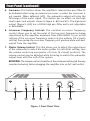
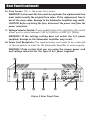
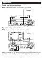
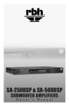
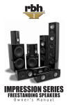
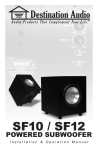
SA-200
/
SA-400
High-Performance Subwoofer Amplifier
Owner’s Manual
Introduction
Congratulations on your purchase of an RBH Sound Subwoofer Amplifier!
Your RBH Subwoofer Amplifier is the result of many years of research and
development dedicated to producing high quality power amplification for
home audio subwoofer systems.
This manual contains operating procedures for the RBH SA-200 and SA-400.
It is recommended you thoroughly read the material contained in this manual
before making any connections to your subwoofer amplifier. This will ensure
you have a good understanding of how to set-up and operate your subwoofer
amplifier for optimum performance.
Front Panel
The following are descriptions of the front panel functions (refer to figure 1).
NOTE: When buttons are pushed in they are in the “on” position.
1. Power Button: This button allows the amplifier to be turned on and off
manually or when kept in the “on” position and the Auto Button (see
figure 1, #2) is kept in the “on” position; the amp will automatically turn
on when it detects an incoming audio signal. The power indicator light
above the power button will glow when the amplifier is on.
IMPORTANT! The volume control should be set at the minimum setting
(all the way counter-clockwise) before plugging the amplifier into an
A/C wall outlet.
2. Auto Button: This button, when in the “on” position, allows the amplifier
to automatically turn on when there is an incoming audio signal present
at either the “Line” inputs or “From Receiver/Speaker Level” inputs. For
this function to work properly, the Power Button must be left in the
“on” position. The light above the Auto Button will glow when the unit
is in “standby” mode. No other lights will glow.
3. Boost: This button, when in the “on” position, will increase output at 25Hz
by 4dB. Use this button with discretion and caution as some subwoofers
may not be able to handle this extra boost. RBH does not recommend using
this feature with the following RBH products: SI-10, TS-10AN, or MCS-88.
4. Phase Control: This knob changes the output phase of the amplifier.
Changing the phase will change the way the subwoofer(s) and main
speakers interact with each other at the crossover frequency. Typically,
this will be set to the 0° position. To operate, press then release the phase
button. While it is extended, adjust as necessary if any problem between
the subwoofer and main speakers exist. Press the button back in.
1
Front Panel (continued)
5. Crossover: This button allows the amplifier’s internal low-pass filter to
be defeated when using an external crossover, or when the crossover is
not needed. When defeated (off), the subwoofer output will play the
full-range of the audio signal. This button has no effect on the high
level inputs and outputs shown in figure 2, #10 and #11. The high level
output (figure 2, #10) has a 100Hz high pass filter and is not adjustable
or defeatable.
6. Crossover Frequency Control: The variable crossover frequency
control allows you to set the point of the low-pass frequencies being
reproduced by the amplifier anywhere from 40Hz-180Hz. Try an initial
setting of the crossover frequency control at the midway (12 o’clock)
setting. Increasing the crossover frequency will produce more mid-bass
output from the amplifier.
7. Master Volume Control: This dial allows you to adjust the output level
of the subwoofer to match the audio system. For an initial setting, turn
the volume control up one quarter of a turn (9 o’clock) position). The
volume control may be adjusted while listening to match the subwoofer
output level with the rest of the system.
REMINDER–The volume control should be at the minimum setting (all the way
counter-clockwise) before plugging the amplifier into an A/C wall outlet.
Figure 1 Front Panel View
2
Rear Panel
The following describes the control functions of the rear panel of the
amplifier (refer to figure 2).
8. Line/LFE Input: These RCA type terminals are for the pre-amp
level input signals coming from a processor or preamplifier labeled
“subwoofer” or “LFE.”
IMPORTANT! Use either the Line Level inputs or the “Speaker Level”
inputs separately. DO NOT use both, as damage to the receiver and/or
the Subwoofer Amplifier may result.
WARNING! DO NOT connect an amplified or speaker-level signal into
the line/LFE input(s).
9. Line/LFE Output: These RCA type terminals carry the same audio signal
as the line inputs. These terminals are used if an output signal is needed
elsewhere in your system. These outputs are full-range outputs.
10.Speaker Level Output: This 100Hz high-pass speaker output is for your
satellite/main speakers. The built-in crossover limits the frequencies
below 100Hz from being sent to your satellite/main speakers. You may
use these speaker outputs only when using the “Speaker Level” input
terminals (#11). Connect your satellite/main speakers (observing the
proper polarity) to the binding posts labeled “Speaker Level Out.”
NOTE: These connectors are not powered by the Subwoofer Amplifier.
11. Speaker Level Input: These connectors are for the amplifier or speakerlevel audio output from an amplifier or receiver.
IMPORTANT! Use either the Line inputs or the “Speaker Level” inputs
separately. DO NOT use both, as damage to the receiver and/or the
Subwoofer Amplifier may result.
12.Subwoofer Output: This is the amplified audio output of the Subwoofer
Amplifier. If the Crossover Button (#5) is in the “on” position, the audio
output will be limited to the lower frequencies selected by the Frequency
Control (#6). If the Crossover Button (#5) is in the “off” position, the
audio output will be full-range. An impedance load of 4-16 ohms may be
connected to this output. Please follow the instructions in the connections
section of this owner’s manual for proper wiring information.
13 Dimmer: This knob adjusts the brightness of the indicator lights on the
front panel.
3
Rear Panel (continued)
14.Fuse Access: This is the power fuse access.
WARNING! In the event the fuse must be replaced, the replacement fuse
must match exactly the original fuse value. If the replacement fuse is
not of the same value, damage to the Subwoofer Amplifier may result.
CAUTION! Before replacing the fuse, disconnect the power cord from the
power receptacle.
15.Voltage Selector Switch: If your model features this capability, this switch
allows you to select between 110V A/C (60Hz) or 220V A/C (50Hz).
WARNING! If the voltage setting does not match the A/C power
supplied, damage to the Subwoofer Amplifier may result.
16.Power Cord Receptacle: The supplied power cord needs to be connected
to this receptacle in order for the Subwoofer Amplifier to work properly.
WARNING! Make certain that you are using the proper power cord
and voltage selection for the type of A/C power supplied.
Figure 2 Rear Panel View
4
Connections
System One: Using line level inputs.
NOTE: Speaker-level inputs are not used in this system.
System Two: Using speaker level inputs.
NOTE: Line level inputs are not used in this system.
NOTE: This example is for speaker level input only. DO NOT connect the left
and right satellite speakers to the amplifier if the line inputs are used.
5
Troubleshooting
Situation:
Probable Cause:
Solution:
No sound from the
subwoofer(s)
Amplifier is not connected
to constant A/C power
outlet.
Make certain the amplifier is
plugged into an unswitchable
A/C power outlet
Subwoofer(s) is/are not
connected to the amplifier
correctly
Make certain that subwoofer(s)
is/are connected properly
(refer to the connections
section of this manual)
Amplifier is not receiving an
audio signal for the
pre-amp/receiver
Maker certain there is an
audio signal from preamp/receiver and audio
connections resemble those
in the connections section
of this manual.
Electrical short in wiring
Verify that all connections
are complete and secure,
with no stray wires
contacting other terminals.
Amplifier fuse might be
blown
Replace fuse (if fuse is not
readily accessible, consult
your authorized RBH
dealer). WARNING: Before
replacing fuses, please see
the rear panel features/
controls section (Figure 2,
#14) of this manual.
Bad connection(s) to nonworking subwoofer(s)
Verify all wires are properly
connected.
Electrical short in wiring
Verify that all connections
are complete and secure,
with no stray wires
contacting other terminals.
If problem is in wire itself,
replace the suspect wire.
If one subwoofer is damaged
due to being overdriven,
then it may have a negative
effect on another subwoofer
used in a series connection.
Check each individual
subwoofer to verify each is
still operational
Sound from at least one
subwoofer, but not the
other(s)
6
Troubleshooting (continued)
Situation:
Probable Cause:
Solution:
Performance is less than
expected
The + and – polarity of the
subwoofer wire might be
reversed on the subwoofer
Check the entire system for
proper polarity
Crossover frequency is not
adjusted correctly
Adjust crossover frequency
by turning the Crossover
Frequency Control clockwise
until desired sound is
obtained
Crossover button is in the
wrong position
Check Crossover On/Off
button for correct setting
7
Specifications
Model
SA200
SA400
Amplifier Type:
Discrete Class A/B
Discrete Class A/B
Recommended/
Rated Power:
200 Watts (RMS @ 4 Ohms)
400 Watts (RMS @ 4 Ohms)
Maximum Power
Consumption:
400 Watts
800 Watts
Distortion (THD):
< .04% @ 1 Watt
< .03% @ 1 Watt
S/N Ratio:
>82dB (without filter)
>84dB (without filter)
Input Impedance:
47 KOhms (line level)
200 Ohms (speaker level)
KOhms (line level)
200 Ohms (speaker level)
Input Sensitivity:
80mV (line input)
80mV (line input)
280mV (speaker level)
280mV (speaker level)
Crossover Slope:
12dB/octave
12dB/octave
Crossover Frequency Range:
40Hz–180Hz ±3dB (variable)
40Hz–180Hz ±3dB (variable)
Auto Turn-on Sensitivity:
1.8mV
1.8mV
Turn-off Delay
Time:
15-20 minutes
15-20 minutes
Frequency Response:
20Hz–20kHz ±3dB (crossover off)
15Hz–20kHz ±3dB (crossover on)
20Hz–20kHz ±3dB (crossover off)
15Hz–20kHz ±3dB (crossover on)
Boost:
±4dB @ 25Hz (when activated)
±4dB @ 25Hz (when activated)
Damping Factor:
>200
>200
Chassis Color:
Black
Black
Cutout Dimensions:
Rack Mount Holes (Center to Center)
Horizontal 18¾” (476mm)
Vertical 3” (76mm)
Rack Mount Holes (Center to Center)
Horizontal 18¾” (476mm)
Vertical 3” (76mm)
Dimensions:
17” W x 4” H x 13” D (w/o rack)
(450mm W x 101mm H x 355mm D)
19” W x 4” H x 14” D (with rack)
(482mm W x 101mm H x 355mm D)
17” W x 4” H x 13” D (w/o rack)
(450mm W x 101mm H x 355mm D)
19” W x 4” H x 14” D (with rack)
(482mm W x 101mm H x 355mm D)
Weight:
17 lbs. (7.71 Kg)
25 lbs. (11.34 Kg)
8
Safety Instructions
CAUTION! DO NOT open the amplifier, attempt any modifications or repairs.
There are extremely high voltages present and any servicing must be referred
to RBH Sound or an authorized qualified technician.
ATTENTION! Opening the amplifier will void warranty.
WARNING! To prevent shock or fire hazard, never permit moisture or any
liquid to get into the amplifier. If an accidental spill occurs, immediately
shut off the power, unplug its A/C power cord and seek a qualified
technician for repair.
CAUTION! To reduce the risk of electric shock, do not remove the cover (or back).
No user serviceable parts inside: refer servicing to qualified technician.
All safety instructions should be read before this amplifier is operated. Please
retain these safety instructions for future reference. Adhere to all warnings
on the amplifier and in this manual.
Ventilation: The amplifier should be situated so that its location or position
does not interfere with its proper ventilation. The amplifier should not be
situated on a bed, sofa, rug or similar surface that may block the ventilation
openings, nor should it be placed in a built-in installation such as a bookcase or
cabinet that may impede the flow of air through the ventilation openings.
Power Source: The amplifier should only be connected to a power supply of
the type described in this instruction manual or as marked on the amplifier.
Precautions should be taken so that the grounding or polarization means of
the amplifier are not defeated.
Power Cords: Power supply cords should be routed so that they are not likely
to be walked on or pinched by items placed upon or against them, paying
particular attention to wall receptacles and the point where they exit from
the amplifier.
Object and Liquid Entry: The amplifier should not be exposed to dripping
or splashing and objects filled with liquids, such as vases or plants, should
not be placed on top of or next to the amplifier. Care should be taken so that
objects do not fall and liquids are not spilled into the enclosure through its
ventilation openings.
Damage Requiring Service: This amplifier should be serviced by a qualified
technician when:
—The power supply cord has been damaged; or
—Objects have fallen or liquid has been spilled into the amplifier; or
—The amplifier does not appear to function normally or exhibits a
marked change in performance; or
—The amplifier has been dropped or the enclosure is damaged.
9
Warranty
Your RBH Sound SA-200/SA-400 is covered by a limited warranty against
defect in materials and workmanship for a period of one year from date of
purchase. This warranty is provided by the authorized RBH Sound dealer
where the SA-200/SA-400 was purchased. Warranty repair will be performed
only when your purchase receipt is presented as proof of ownership and date
of purchase. Defective parts will be repaired or replaced without charge
by your dealer’s store or the location designated by RBH Sound authorized
to service RBH Sound products. Charges for unauthorized service and
transportation cost are not reimbursable under this warranty.
This warranty becomes void if the product has been damaged by alteration,
misuse or neglect. RBH Sound assumes no liability for property damage or
any other incidental or consequential damage whatsoever which may result
from the failure of this product. Any and all warranties of merchantability
and fitness implied by law are limited to the duration of this expressed warranty. Some states do not allow limitations on how long an implied warranty
lasts, so the above limitations may not apply to you. Some states do not
allow the exclusion or limitation of incidental or consequential damages,
so the above limitation or exclusion may not apply to you.
Redefining The Way You Experience Sound.
TM
382 Marshall Way, Layton, Utah • USA • 84041
Toll Free: (800) 543-2205 • Fax: (801) 543-3300
www.rbhsound.com
It is RBH Sound policy to continuously incorporate improvements into products; all specifications are subject to change without notice.
Copyright © 2007 RBH Sound. All Rights Reserved.