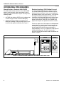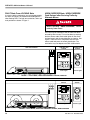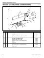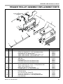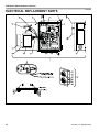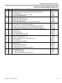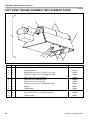
1
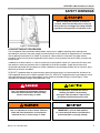
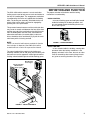
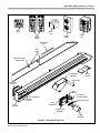
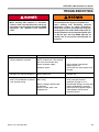
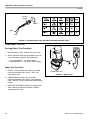
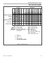
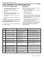
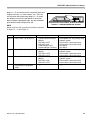
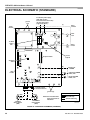
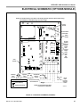
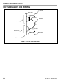
GWL-2300 Wheel-LokTM
Vehicle Restraint
Owners Manual
MADE IN U.S.A.
This Manual Covers Restraints Built After Serial Numbers:
GW231001 and up
PRINTED IN U.S.A.
RITE-HITE PRINT SHOP
PUBLICATION NO. 1177
NOVEMBER 2010
RITE-HITE® GWL-2300 Owner’s Manual
TABLE OF CONTENTS
INTRODUCTION . . . . . . . . . . . . . . . . . . . . . . . . . . . . . . . . . . . . . . . . . . . . . . . . . . . . . . . . . . . . . . . . . . . . . . . . .. . 2
SAFETY WARNINGS . . . . . . . . . . . . . . . . . . . . . . . . . . . . . . . . . . . . . . . . . . . . . . . . . . . . . . . . . . . . . . . . . . . . . . . 3
OWNER RESPONSIBILITY . . . . . . . . . . . . . . . . . . . . . . . . . . . . . . . . . . . . . . . . . . . . . . . . . . . . . . . . . . . . . . . . . . 4
DEFINITION AND FUNCTION. . . . . . . . . . . . . . . . . . . . . . . . . . . . . . . . . . . . . . . . . . . . . . . . . . . . . . . . . . . . . . . . . 5
FEATURES . . . . . . . . . . . . . . . . . . . . . . . . . . . . . . . . . . . . . . . . . . . . . . . . . . . . . . . . . . . . . . . . . . . . . . . . . . . . . . 6
OPERATING PROCEDURES & TESTING . . . . . . . . . . . . . . . . . . . . . . . . . . . . . . . . . . . . . . . . . . . . . . . . . . . . . . . 8
MAINTENANCE (BASED ON TYPICAL APPLICATIONS OF 8 TRUCKS PER DAY). . . . . . . . . . . . . . . . . . . . . . . . 13
TROUBLESHOOTING . . . . . . . . . . . . . . . . . . . . . . . . . . . . . . . . . . . . . . . . . . . . . . . . . . . . . . . . . . . . . . . . . . . . . . . 15
HORN OVERRIDE CODE AND DIAGNOSTICS . . . . . . . . . . . . . . . . . . . . . . . . . . . . . . . . . . . . . . . . . . . . . . . . . . . . 18
ELECTRICAL SCHEMATIC . . . . . . . . . . . . . . . . . . . . . . . . . . . . . . . . . . . . . . . . . . . . . . . . . . . . . . . . . . . . . . . . . . 20
REPLACEMENT PARTS . . . . . . . . . . . . . . . . . . . . . . . . . . . . . . . . . . . . . . . . . . . . . . . . . . . . . . . . . . . . . . . . . . . . . . . 24
WARRANTY . . . . . . . . . . . . . . . . . . . . . . . . . . . . . . . . . . . . . . . . . . . . . . . . . . . . . . . . . . . . . . . . . . . . . . . BACK COVER
INTRODUCTION
Read and understand this manual before attempting to install or operate. For best results, have this product serviced
by your authorized RITE-HITE® representative.
The GWL-2300 vehicle restraint by RITE-HITE is intended to provide a safer workplace for workers in shipping and
receiving dock areas. The GWL-2300 vehicle restraint is a restraint device that, when properly installed and operated,
retains a secure connection between the truck and dock. Signal lights, warning horn and signs provide instructions to
the truck driver and GWL-2300 vehicle restraint operator that a safe condition exists. The GWL-2300 vehicle restraint
is operated by pressing push buttons on an inside control box.
NOTICE TO USER
®
Your local RITE-HITE representative provides a Planned Maintenance Program (P.M.P.) which can be fitted to your
®
specific operation. Call your local representative or the RITE-HITE Corporation at 414-355-2600.
®
The RITE-HITE products in this manual are covered by one or more of the following U.S. patents: 5,271,183;
5,323,503; 5,546,623; 5,553,987; 5,582,498; 5,664,930; 5,702,223; 5,762,459 (RE: 37,570); 5,882,167; 6,065,172;
6,070,283; 6,085,375; 6,092,970; 6,106,212; 6,116,839; 6,190,109; 6,220,809; 6,276,016; 6,311,352; 6,318,947;
6,322,310; 6,360,394; 6,368,043; 6,431,819; 6,488,464; 6,499,169; 6,502,268; 6,505,713; 6,524,053; 6,634,049;
6,654,976; 6,726,432; 6,773,221; 6,832,403; 6,880,301; 6,892,411; 7,032,267; 7,062,814; 7,134,159; 7,213,285;
7,216,391; 7,363,670; 7,380,305; 7,503,089; 7,553,431; 7,578,097; 7,681,271 and pending U.S and foreign patent
®
®
TM
®
®
TM
®
applications. RITE-HITE , LEVEL-RITE , THINMAN , SAFE-T-LIP , HYDRACHEK , WHEEL-LOK , DOK-LOK ,
®
TM
®
TM
TM
®
DUAL-DOK , SAFE-T-STRUT , DOK-COMMANDER , JUMBO , HYDRA-RITE , SAFE-T-GATE , and SMOOTH
TM
®
TRANSITION DOK SYSTEM , are trademarks of RITE-HITE Corporation.
2
Pub. No. 1177 - November 2010
RITE-HITE® GWL-2300 Owner’s Manual
SAFETY WARNINGS
When working with electrical or electronic
controls, make sure that the power source has
been locked out and tagged according to OSHA
regulations and approved local electrical codes.
Figure 1 - Lockout/Tagout
LOCKOUT/TAGOUT PROCEDURES
The Occupational Safety and Health Administration requires that, in addition to posting safety warnings and
barricading the work area, the power supply has been locked in the OFF position or disconnected. It is mandatory
that an approved lockout device is utilized. An example of a lockout device is illustrated. The proper lockout
procedure requires that the person responsible for the repairs is the only person who has the ability to remove the
lockout device.
In addition to the lockout device, it is also a requirement to tag the power control in a manner that will clearly note
that repairs are under way and state who is responsible for the lockout condition. Tagout devices have to be
constructed and printed so that exposure to weather conditions or wet and damp locations will not cause the tag to
deteriorate or become unreadable.
RITE-HITE® Corporation does not recommend any particular lockout device, but recommends the utilization of an
OSHA approved device (refer to OSHA regulation 1910.147). RITE-HITE® Corporation also recommends the review
and implementation of an entire safety program for the Control of Hazardous Energy (Lockout/Tagout). These
regulations are available through OSHA publication 3120.
This is the highest level statement. Failure to
follow the listed instructions will most likely
result in severe injury or death.
The statements used with this level of
warning deal with a safe operating
procedure. If the procedure is ignored, the
possibility of personal injury may exist.
This is a statement of serious hazard. Failure to
follow the listed instructions could place the
individual at risk of serious injury or death.
IMPORTANT is used to draw attention
to a procedure that needs to be followed to
prevent machine or property damage.
Pub. No. 1177 - November 2010
3
RITE-HITE® GWL-2300 Owner’s Manual
OWNER RESPONSIBILITY
1.
The owner should recognize the inherent danger of
the interface between dock and transport vehicle.
The owner should, therefore, train and instruct
operators in the safe use of dock equipment in
accordance with the information provided below.
The manufacturer shall publish, provide to the initial
purchaser, and make the following information
readily available to owners:
5.
As with any piece of machinery, dock equipment
requires routine maintenance, lubrication, and
adjustments. Your local RITE-HITE® representative
offers owners the option of a Planned Maintenance
Program (P.M.P.). As part of this service, your local
RITE-HITE® representative will do all routine
maintenance, lubrication, and adjustments.
6.
Dock equipment that is structurally damaged shall
be removed from service, inspected by a
manufacturer’s authorized representative, and
repaired as needed before being placed back in
service.
7.
The manufacturer shall make available replacement
nameplates, caution/instruction labels, and
operating/maintenance manuals upon request of the
owner. The owner shall see that all nameplates,
caution/instruction markings or labels are in place
and legible, and that the appropriate
operating/maintenance manuals are provided to
users.
8.
Modifications or alterations of dock equipment shall
be made only with written permission of the original
manufacturer. These changes shall also satisfy all
safety recommendations of the original equipment
manufacturer for the particular application of the
dock equipment.
9.
When industrial trucks are driven on and off
transport vehicles during the loading and unloading
operation, the brakes on the transport vehicle shall
be applied and wheel chocks or a positive
restraining device shall be engaged.
• Installation instructions
• Recommended initial and periodic inspections
procedures
• Maintenance procedures
• Operating instructions
• Descriptions or specifications for replaceable or
repairable parts
• Tables identifying the grade (slope) for all
variations of length or configuration of the dock
equipment, and
• Information identifying the maximum uncontrolled
drop encountered upon sudden removal of
support while within the working range of the
equipment.
It shall be the responsibility of the owner to verify
that the material listed in this section has been
received and that it is made available for the
instruction and training of personnel entrusted with
the use or maintenance of the dock equipment.
2.
When a transport vehicle is parked at a loading
dock, it is important that the vehicle is relatively
perpendicular to the dock face and in close contact
with at least one of the dock bumpers.
3.
Nameplates, cautions, instructions, and posted
warnings shall not be obscured from the view of
operating or maintenance personnel for whom such
warnings are intended.
4.
Manufacturer’s recommended periodic maintenance
and inspection procedures in effect at date of
shipment shall be followed, and written records of
the performance of these procedures should be kept.
4
10.
In selecting dock equipment, it is important to
consider not only present requirements but also
future plans or adverse environments.
Pub. No. 1177 - November 2010
RITE-HITE® GWL-2300 Owner’s Manual
DEFINITION AND FUNCTION
The GWL-2300 vehicle restraint is a truck and trailer
locking system used to help secure trucks and trailers to
the face of a loading dock. The engagement mechanism
is positioned by the trailer as it approaches the loading
dock. The locking arm assembly, which blocks the rear
wheel of the truck or trailer, can then be engaged by
pressing the LOCK push button.
The proper activation of the barrier and the locking
mechanism is monitored by:
• VISUAL CONTROL
– one set of flashing green and red lights located
inside the building for the dock personnel, and
one set located outside the building for the truck
driver. See Figure 2.
This prevents forward movement of the truck/trailer that
may create an unsafe void between the face of the dock
and the rear end of the truck/trailer as the forklift travels
from the loading dock onto the trailer; and creates an
obstruction noticeable (via outside lights) to the truck
driver, should the driver accidentally try to pull the truck/
trailer away while it is being serviced.
NOTE
There is no need to hold button to maintain its function.
Once a button is depressed, the GWL-2300 vehicle
restraint will lock or unlock for a preset time interval.
The normal mode of the restraint is the locking arm
assembly stored at the far end (away from the dock) with
the barrier arm on the approach. Inside lights should be
flashing red and outside lights should be flashing green.
FIGURE 3 - AUDIO CONTROLS
• AUDIO CONTROL
– a horn sounds inside the building, warning dock
personnel when the locking mechanism is not
properly activated. In this case, the truck or trailer
must be secured by other means (wheel chocks
etc.) prior to servicing the trailer. See Figure 3.
Inside Control Box
With Red And
Green Lights
Outside Light Box
With Red And
Green Lights
FIGURE 2 - VISUAL CONTROLS
Pub. No. 1177 - November 2010
5
RITE-HITE® GWL-2300 Owner’s Manual
FEATURES
See Figure 4 for locations of these features.
HYDRAULIC CYLINDER
Moves the Lifting Rails back and forth, thus raising or
lowering the locking pawl into place.
PAWL ASSEMBLY
Assembly
which is driven upward into the ratchet by the Lifting Rails
when the unit is locked.
POWER UNIT ENCLOSURE
TRIGGER ASSEMBLY
Houses the 120 VAC Hydrualic Power Unit and terminal
block assembly.
Component which is contacted by the rearmost tire of a
trailer. When a tire engages the trigger, it will pull the
locking arm assembly into its UP position, and pull the
locking arm assembly along the frame assembly.
BARRIER SHAFT
The shaft which serves as the restraining obstruction in
front of the rearmost tire. It is connected to the locking
arm assembly.
TRIGGER TROLLEY ASSEMBLY
The trigger trolley assembly holds the trigger assembly to
the frame.
BARRIER RAMP
The assembly that the barrier shaft stores in. Barrier
ramp is used to protect the barrier shaft when a
truck/trailer backs into place.
EXTENSION SPRINGS
FRAME ASSEMBLY
LOCK SENSOR (SW1)
The main weldment which is bolted onto the approach. It
acts as a guide/rail for the locking arm assembly, trigger
trolley, and lock trolley.
Communicates to the control box whether or not the unit
is locked. (Not shown, See page 26)
LOCKING ARM ASSEMBLY
The assembly which is rotated up into its UP position
when a trailer backs into the dock.
LOCKING ARM TROLLEY ASSEMBLY
Locking arm trolley assembly holds the locking arm
assembly to the frame and houses the pawl assembly.
LIFTING RAILS
The component which is pushed by the hydraulic cylinder.
It rides upon diagonal slotted plates along the frame. The
vertical motion drives the locking pawl into the ratchet.
6
The extension springs connect the locking arm trolley to
the trigger trolley.
UNLOCK SENSOR (SW2)
Communicates to the control box whether or not the unit
is unlocked. (Not shown, See page 26)
PAWL HOLD DOWN
Mechanically senses if a trailer tire is present when the
locking arm is raised.
CONTROL BOX, OUTSIDE LIGHT BOX, AND
SIGNAGE
The
combination of these components are uses to control the
function of the GWL-2300 Wheel Restraint and provide
audio/visual communication to the dock attendant and the
trailer driver.
Pub. No. 1177 - November 2010
RITE-HITE® GWL-2300 Owner’s Manual
Inside
Sign
Anchor
Kit
Control
Box
Outside
Lights
Outside
Signs
Maintenance
Strut
Side
Covers
Maintenance Strut
Storage Hooks
Barrier
Ramp
Locking Arm
Assembly
Barrier Shaft
Power Unit
Enclosure
Pawl
Assembly
Locking Arm
Trolley Assembly
Lifting Rails
Hydraulic
Cylinder
Frame
Assembly
Extension Springs
Pawl
Hold Down
Trigger Trolley
Assembly
Trigger
Assembly
FIGURE 4 - FEATURES OF GWL-2300
Pub. No. 1177 - November 2010
7
RITE-HITE® GWL-2300 Owner’s Manual
OPERATING PROCEDURES
Stored Position / Restraint UNLOCKED
Restraint Locking, LOCK Button Pressed
If the GWL-2300 vehicle restraint is in the UNLOCKED
position (shaft assembly is down and stored in barrier
ramp), the Light Communication System should give the
following signals:
It is assumed that the loading bay is empty (no truck).
The outside GREEN light and the inside RED light are
flashing, the barrier is down. A truck can now approach
the loading position. As the truck backs in, it will activate
the trigger, causing the locking arm to come up. The
mechanism will automatically adjust to the correct wheel
size. The truck will move locking arm and trolleys into
position automatically. When the truck is parked firmly
against the bumpers, the operator can lock the vehicle.
1. OUTSIDE light flashing GREEN, which indicates that
a vehicle may pull into or out of the loading bay.
2. INSIDE light flashing RED, which indicates that
loading or unloading is not permitted, since the truck
is not secured against the building. See Figure 5.
GWL-2300 POSITION
To lock the vehicle, the LOCK button must be depressed
momentarily. The outside light will change instantly from
flashing GREEN to flashing RED. The inside light will
remain steady RED until the locking mechanism is
engaged properly. Once it is engaged, the inside light will
change to flashing green. The truck may now be
serviced. The light communication and truck position are
shown in Figure 6.
CONTROL BOX
STATUS
OUTSIDE LIGHT
STATUS
RED
RED
GREEN
1
2
LOCK
GREEN
3
HORN OVERRIDE
UNLOCK
Inside Lights
Outside Lights
FIGURE 5 - STORED POSITION, INSIDE RED LIGHT AND OUTSIDE GREEN LIGHT
8
Pub. No. 1177 - November 2010
RITE-HITE® GWL-2300 Owner’s Manual
Restraint LOCKED
If the GWL-2300 vehicle restraint is in the LOCKED
position with the barrier up and the locking mechanism
engaged properly, the Light Communication System
should give the following signals:
1. OUTSIDE light flashing RED, indicating that the truck
driver is not permitted to leave.
2. INSIDE light flashing GREEN, indicating that the
truck may now be loaded or unloaded. See Figure 6.
Restraint UNLOCKING, UNLOCK Button
Pressed
In order to release the truck after completion of the
loading/unloading process, the UNLOCK pushbutton
must be pressed. The inside light will turn instantly to
steady RED, while the outside light remains flashing
RED until the locking mechanism is disengaged. The
outside light will turn to flashing GREEN, allowing the
truck to depart. The truck will automatically move the
locking arm to the stored position when departing.
NOTE:
If testing without a trailer present, make sure to
manually separate trollies so pawl hold down is
disengaged.
GWL-2300 POSITION
On occasion the truck/trailer may move forward
during servicing putting pressure on the pawl
assembly. If an unlock “Fault” occurs the
truck/trailer may need to be positioned firmly
against the dock bumpers to release the
pressure on the pawl assembly.
CONTROL BOX
STATUS
OUTSIDE LIGHT
STATUS
RED
RED
GREEN
1
2
LOCK
GREEN
3
HORN OVERRIDE
UNLOCK
Inside Lights
Outside Lights
FIGURE 6 - TRUCK LOCKED AGAINST THE BUMPERS
Pub. No. 1177 - November 2010
9
RITE-HITE® GWL-2300 Owner’s Manual
FAULT State From LOCKING State
In case the locking mechanism can not engage properly,
the alarm will sound. The outside and inside lights will
show flashing RED. The light communication, alarm and
truck position are shown in Figure 7.
HORN OVERRIDE State, HORN OVERRIDE
Code Entered after Securing Trailer by
Alternate Means
Before operating “HORN OVERRIDE”, secure
trailer by other means.
The horn may be silenced AFTER the trailer has been
secured by other means. This can be done by entering
the horn silence code. Both inside lights will now flash
(red and green) and all control buttons are inactive. See
Figure 8. Once service is completed, enter the horn
silence code and press the unlock push button. The
truck/trailer may now depart once GWL-2300 unlocks.
GWL-2300 POSITION
OUTSIDE LIGHT
STATUS
CONTROL BOX
STATUS
RED
RED
1
LOCK
2
Horn
GREEN
3
UNLOCK
HORN OVERRIDE
Inside Lights
Outside Lights
FIGURE 7 - FAULT MODE, TRUCK NOT PROPERLY LOCKED, HORN ON
GWL-2300 POSITION
CONTROL BOX
STATUS
OUTSIDE LIGHT
STATUS
RED
GREEN
RED
1
2
LOCK
GREEN
3
HORN OVERRIDE
UNLOCK
Inside Lights
Outside Lights
FIGURE 8 - FAULT MODE, TRUCK NOT PROPERLY LOCKED, HORN SILENCED
10
Pub. No. 1177 - November 2010
RITE-HITE® GWL-2300 Owner’s Manual
VEHICLE RELEASE DURING LOSS OF POWER
PROCEDURE
1. Lockout/Tagout controls.
Do not remove lock arm when a truck tire is
present.
During loss of power, the GWL-2300 vehicle restraint will
not automatically disengage the vehicle being serviced.
The truck must be manually released by the following
method. See Figure 9.
Remove
Pin
2. Remove pin which connects the hydraulic cylinder to
the Lifting Rails. See figure 9.
3. Place pry bar in hole between end of lifting rail and
frame hole as shown in figure 10. Pry away from the
dock, lowering the lifting rails and disengaging the
locking pawl.
4. Do not use equipment until reassembled.
Place Pry Bar In Hole And
Pry Away From Dock
Lifting
Rail
FIGURE 9 - MANUALLY RELEASING TRUCK
Pub. No. 1177 - November 2010
FIGURE 10 - LOCK RAILS LOWERED
11
RITE-HITE® GWL-2300 Owner’s Manual
SNOW REMOVAL PROCEDURE
Service
Strut
Wheel guides, locking arm assembly, trigger, or
frame assembly may be buried underneath
snow, thus not visible. Unseen obstructions
may cause damage to equipment and/or bodily
harm during snow removal if they should come
into contact with the snow removal equipment.
Engage Locking Arm Assembly With Service Strut
In the event of snow fall, please follow the procedure
below to clear and remove snow from the truck approach.
PROCEDURE
Move To Rearmost Position
1. Using the service strut, move the locking arm
assembly all the way towards the dock face. See
Figure 11.
2. Back drag snow from the approach. Be sure not to hit
the wheel guides, locking arm assembly, trigger,
barrier ramp and frame assembly with the plow.
3. Return the locking arm assembly to the stored
position after completion of snow removal.
4. Remove snow against dock by alternate means
(shovel, snowblower, etc.).
Return To Stored Position
FIGURE 11 - SNOW REMOVAL
RECOMMENDED LIQUID DE-ICER
Any Calcium-Cloride based liquid de-icer.
5. Manually clean on and around unit to prevent ice
build-up.
12
Pub. No. 1177 - November 2010
RITE-HITE® GWL-2300 Owner’s Manual
MAINTENANCE
(BASED ON TYPICAL APPLICATIONS OF 8 TRUCKS PER DAY)
90 DAYS
1. Perform all Daily maintenance.
When working with electrical or electronic
controls, make sure that the power source has
been locked out and tagged according to OSHA
regulations and approved local electrical codes.
Post safety warnings and barricade work area,
at dock level and at ground level, to prevent
unauthorized use of the dock position.
A safe work place requires all lights and the
horn to be working properly. DO NOT use
GWL-2300 vehicle restraint if parts are broken
or missing.
Maintenance may be required more frequently
at loading docks exposed to harsh
environments (extreme climates, corrosive
chemicals, frequency of usage exceeding 8
trucks per day, etc.). Consult RITE-HITE if these
conditions exist for accelerated maintenance
requirements.
®
NOTE: Your local RITE-HITE representative provides a
Planned Maintenance Program (P.M.P.) which
can be fitted to your specific operation. Call your
local representative.
2. Grease rollers at fittings located on both sides of
trolleys (8 places), lock arm trolley pin and barrier
roller. See Figure 23. Use Mobilith SHC220 No. 2
grease (or equivalent temperature range lithium
based grease). Two (2) to three (3) pumps at
subsequent 90 Day maintenance intervals.
Grease Barrier Roller
At Fitting Use Mobilith SCH220
No. 2 Grease
Grease Trolley Pin
At Fitting Use Mobilith SCH220
No. 2 Grease
Grease Rollers (8) At Fittings Use Mobilith SCH220
No. 2 Grease
Both Sides
Lubricate Pawl Shaft
Dry Lubricate Only - DO NOT USE Moly Based Grease
FIGURE 12 - LUBRICATION
3. Lubricate Pawl Guide Shaft with a Dry Spray
Lubricant - DO NOT USE Moly-Based Grease.
DAILY
4. Check the trigger and rollers for damage, ensure
rollers spin freely.
1. Remove dirt, snow, ice and debris around GWL-2300
vehicle restraint.
5. Check brushes on trolleys and replace as necessary.
2. Verify inside, outside lights and horn are working.
3. Replace damaged or missing light bulbs and lenses.
4. Repair, remount, or replace outside and inside signs
as required.
5. Inspect dock bumpers. Missing bumpers must be
replaced.
Pub. No. 1177 - November 2010
6. Inspect outside junction box, light box and power unit
enclosure. They should be rigidly mounted. If loose or
damaged, inspect all wires and wire connections.
7. Inspect flexible conduit from GWL-2300 vehicle
restraint to junction box. Look for kinks, crushed
areas, etc.
8. Perform operational test after all maintenance repairs
are complete.
13
RITE-HITE® GWL-2300 Owner’s Manual
180 DAYS
360 DAYS
1. Do all the Daily and 90 Day maintenance.
1. Do all Daily, 90 and 180 Day maintenance.
2. Tighten the anchor bolts to 100 ft-lbs.
2. Operate unit in (5) different places to ensure the
locking mechanism engages properly.
3. Check barrier roller tube for damage.
4. Check if all the bolts on the UHMW strip are tight.
5. Manually push the locking arm weldment along the
length of the frame to verify smooth operation. If
sticky, check for proper lubrication.
3. Disassemble both the locking arm and trigger trollies
and inspect internal sliders for wear. Replace as
necessary. See Figure 13.
Dock equipment must be protected by 4" thick
bumpers. WORN, TORN, LOOSE, OR MISSING
BUMPERS MUST BE REPLACED.
4. Inspect wear pads in locking arm assembly. See
Figure 13.
5. Inspect pawl mechanism for wear on sliders.
6. Inspect bronze tooth on locking pawl.
7. Verify decals are present and legible, replace as
required.
8. Inspect lifting rail bushings for wear and replace if
worn through to pin hole. Do not lubricate slots in
frame.
Wear Pads
Steel
Trolley Sliders
Pawl
UHMW Blocks
And Slider
Bronze Tooth
Lifting Rail Bushing
5 ea. on Rail
Frame
Wear Strips
FIGURE 13 - INSPECTION
14
Pub. No. 1177 - November 2010
RITE-HITE® GWL-2300 Owner’s Manual
TROUBLESHOOTING
When working with electrical or electronic
controls, make sure that the power source has
been locked out and tagged according to OSHA
regulations and approved local electrical
codes.
Problem
1. Cylinder does not extend when
LOCK pushbutton is pushed.
To prevent personal injury use extreme care
when working with electrically powered
equipment. Follow all safety instructions.
Disconnect all power, and keep body away from
moving parts. Use caution with compressed air;
foreign materials can be blown through the skin
or into the eyes. Use only OSHA approved air
nozzles and do not exceed recommended air
pressure.
Probable Cause
Motor circuit breaker tripped, or bad.
NOTE: A motor fuse is not required,
unit uses circuit breaker only.
Power unit power supply.
Hydraulic system
2. No lights, but 120V at transformer.
Blown control fuse.
3. Unit goes into fault about 8 seconds Bad SW1 (Lock sensor).
after LOCK pushbutton is pushed,
SW1 wiring.
with actuator moving.
Bronze “snaggle” tooth on pawl
is damaged.
Barrier is to low, pawl is not
engaging rack.
Pub. No. 1177 - November 2010
Remedy
Replace or reset.
Check voltage at transformer,
bridge rectifier, etc.
Check fluid level and hydraulic lines
for leaks.
Replace fuse.
Replace SW1 (lock sensor).
Verify wiring per electrical
schematic on page 11 or 12.
Disassemble locking arm trolley and
replace snaggletooth if required.
Back trailer firmly against bumpers.
Trailer bogeys may be too far
forward to service.
15
RITE-HITE® GWL-2300 Owner’s Manual
Sensing
Switch
Magnet
(LED Off)
(LED On)
(LED On)
(LED Off)
White
Black
FIGURE 14 - SENSING SWITCH TEST AND SWITCH/BARRIER POSITION CHART
COMPONENT TESTING
multimeter
Sensing Switch Test Procedure
1. Set multimeter to “RX1” scale for “Continuity Test”.
2. Attach multimeter leads to white and black wires of
mag. reed switch connector. You should have:
— no magnet present — no meter reading.
— magent present — a “Full Scale” meter reading.
3
G
1
2
Motor Test Procedure
1. BAD O/L: Little or infinite ohm reading (no needle
movement) between lead 1 and 2, 1 and 3. Set
multimeter to ohms.
hydraulic power unit
FIGURE 15 - MOTOR TEST
2. OPEN WINDING: Infinite ohms (no needle
movement) between lead 2 and 3. Check between
leads 1 and 2 or 1 and 3 to determine which winding
is open.
3. MECHANICAL BINDING: Motor hums. Motor leads
show continuity between all windings. Hydraulic
cylinder does not move.
16
Pub. No. 1177 - November 2010
RITE-HITE® GWL-2300 Owner’s Manual
LED STATUS CHART
SW2
LOCK PB
UNLOCK PB
PB1,2 & 3
ISR
ISG
OSR
OSG
HORN
M1L
M2L
CR1
CR2
CR3
LED Outputs
SW1
LED Inputs
STORED (UNLOCKED)
F
T
-
-
-
P
F
F
P
F
F
F
F
*
T
LOCKING
F
F
M
-
-
P
F
P
F
F
T
F
F
*
T
LOCKED
T
F
-
-
-
F
P
P
F
F
F
F
T
*
T
STORING (UNLOCKED)
F
F
-
M
-
T
F
P
F
F
F
T
F
*
T
PAWL FAULT
F
F
-
-
-
P
F
F
F
P
F
F
F
*
F
HORN SILENCED
?
?
-
-
M
P
P
P
F
F
F
F
T
*
T
ISR
ISG
OSR
OSG
HORN
M1L
M2L
CR1
CR2
CR3
=
=
=
=
=
=
=
=
=
=
SWI
SW2
LOCK PB
UNLOCK PB
PB1, 2, &3
PAWL FAULT
=
=
=
=
=
=
MAG RES 1 (LOCK)
MAG RES 2 (UNLOCK)
Lock Push Button
Unlock Push Button
Horn Silence Code Push Button
SW1 did not sense a safe
LOCK/UNLOCK
Inside Red Light
Inside Green Light
Outside Green Light
Outside Green Light
Alarm Horn
Motor Up output
Motor Down Output
Green Light Interlock Output
Unidox Output
Security System Output
T = Steady On
D = Double Pulse
F = Off
P = Pulsing/Flashing
* = True when Unidox is enabled
? = Varies depending on operation
FIGURE 16 - LED STATUS CHART
Pub. No. 1177 - November 2010
17
RITE-HITE® GWL-2300 Owner’s Manual
HORN OVERRIDE CODE AND DIAGNOSTICS
SETTING HORN OVERRIDE CODE
DIAGNOSTICS
1. Press and hold DIAGNOSTIC button until horn
chirps (approximately three seconds).
Diagnostic mode may be entered while the restraint is in
any state. To enter diagnostic mode:
1. Press and hold DIAGNOSTIC button until it chirps
(approximately 3 seconds).
2. Enter the factory preset HORN OVERRIDE
code:1223.
2. Press the LOCK button.
3. Enter the new HORN OVERRIDE code. The code
can be one to four numbers in length.
3. Press the UNLOCK button.
4. The horn chirps and the outside light is flashing red.
The controls are in the first step of diagnostic mode.
NOTE: The outside red light will remain flashing at
all times except Step 5.
4. Once the new code has been entered, press the
LOCK button.
5. Controls reset with new HORN OVERRIDE code
enabled.
If no buttons are pressed within a five minute period, the
controls will automatically retain the previous code. To
exit the HORN OVERRIDE code set mode at any time,
press the DIAGNOSTIC button.
If code has been forgotten, follow the above procedures
and enter a new code.
Operator Action
Press LOCK - Go to Step 2
Step 2
Press
Press
Press
Press
Press
UNLOCK - Go to Step 1
LOCK - Go to Step 3
UNLOCK - Go to Step 2
LOCK - Go to Step 4
UNLOCK - Go to Step 3
Press
Press
Press
Press
Press
Press
Press
LOCK - Go to Step 5
UNLOCK - Go to Step 4
LOCK - Go to Step 6
UNLOCK - Go to Step 5
LOCK - Go to Step 7
UNLOCK - Go to Step 6
LOCK - Go to Step 8
Step 4
Step 5
Step 6
Step 7
Step 8
Press
Press
Step 9 Press
Press
Step 10 Press
Press
Step 11 Press
Press
18
UNLOCK - Go to Step
LOCK - Go to Step 9
UNLOCK - Go to Step
LOCK - Go to Step 10
UNLOCK - Go to Step
LOCK - Go to Step 11
UNLOCK - Go to Step
LOCK - Go to Step 12
If no buttons are pressed within a five minute period, the
controls will automatically exit the diagnostic mode. To
exit the diagnostic mode at any time, press the
DIAGNOSTIC button.
Outputs
Step 1
Step 3
5. Start at Step 1 in the Diagnostic Table. If the
equipment Outputs do not match the table, use the
Troubleshooting section on page 15.
7
Outside red light is flashing.
OSR LED is flashing.
Inside red light is ON.
ISR LED is ON.
Inside Green light is ON.
ISG LED is ON.
Inside amber light is ON (if
not equipped, go to Step 5).
ISA LED is ON.
Outside red light is ON.
OSR LED is ON.
Outside green light is flashing.
OSG LED is flashing.
Horn is ON.
HRN LED is ON.
Troubleshooting
Check
Check
Check
Check
Check
Check
Check
light bulb and wiring.
CPU module and 1 amp fuse.
light bulb and wiring.
CPU module and 1 amp fuse.
light bulb and wiring.
CPU module and 1 amp fuse.
light bulb and wiring.
Check CPU module and 1 amp fuse.
Check light bulb and wiring.
Check CPU module and 1amp fuse.
Check light bulb and wiring.
Check CPU module and 1 amp fuse.
Check horn and wiring. Test horn
applying 12V DC power.
Check CPU module and 1 amp fuse.
Check Option module.
8
CR1 LED is ON. (If option
card installed, go to Step 12).
CR2 LED is ON.
Check Option module.
9
CR3 LED is ON.
Check Option module.
10
Outside red light is flashing.
OSR LED is flashing.
See Step 1.
Pub. No. 1177 - November 2010
RITE-HITE® GWL-2300 Owner’s Manual
Steps 12 – 15 are used to test the mechanical Inputs and
Outputs of the lock (i.e. motor, sensors, etc.). The horn
will chirp when the controls enter Steps 12 – 15 to alert
the operator to check the hook position. If the sensor
does not read the appropriate input, the horn will double
pulse and the inside red light will be ON.
NOTE
Barrier must be in the up position and trolleys separated
for Steps 12 – 15. See Figure 17.
Operator Action
Step 12
Press LOCK - Go to Step 13.
Step 13
Press LOCK - Go to Step 14.
Step 14
Press LOCK - Go to Step 16.
Step 15
Press LOCK - unit will unlock,
and controls exit Diagnostic
mode.
Pub. No. 1177 - November 2010
FIGURE 17 - BARRIER RAISED FOR TESTING
Outputs
Cylinder retracts to stored
position.
SW1 LED is OFF.
SW2 LED is ON.
Inside red light is ON.
Outside red light is flashing.
Cylinder extends to fault
position
SW1 LED is OFF.
SW2 LED is OFF.
Cylinder extends to lock
position.
SW1 LED is ON.
SW2 LED is OFF.
___
Troubleshooting
Check power unit, verify wiring, verify
hydraulic system.
Check switch 1 and verify wiring.
Check switch 2 and verify wiring.
See Step 2.
See Step 5.
Check power unit, verify wiring, verify
hydraulic system.
Check switch 1 and verify wiring.
Check switch 2 and verify wiring.
Check power unit, verify wiring, verify
hydraulic system.
Check switch 1 and verify wiring.
Check switch 2 and verify wiring.
___
19
RITE-HITE® GWL-2300 Owner’s Manual
ELECTRICAL SCHEMATIC (STANDARD)
to customer power supply,
120V, 60Hz, 30 amp
fused disconnect with 10 amp
non-time delay fusing
(supplied by others)
ground
lugs
(1)
motor
common
power
module
1A, 250V
control
fuse
(2)
motor
lock
(3)
motor
unlock
no fuse
required
to option module
diagnostic
button
(42)
CPU
module
(5) (6)
5
6
outside light
POWER
(41)
outside light GREEN
12VDC, 2.1A
(40)
outside light RED
12VDC, 2.1A
(7)
7
Located in frame
mounted enclosure
ground lugs
white
black
“LOCKED”
Sensor Switch
(SW1)
LEGEND
white
black
NOTE: Use included female
spade connectors for
installation.
“UNLOCKED”
Sensor Switch
(SW2)
label LED lamp
denotes field wiring
5631D028
FIGURE 18 - ELECTRICAL SCHEMATIC (STANDARD)
20
Pub. No. 1177 - November 2010
RITE-HITE® GWL-2300 Owner’s Manual
ELECTRICAL SCHEMATIC (OPTIONS MODULE)
NOTE: The standard wiring is not shown in this drawing to better show the option module wiring.
For information on standard wiring, see previous page.
power
module
circuit breaker
reset button
option
module
security
system
interface
output
unidox
interconnect
output
green
light
interlock
output
CPU
module
raise
photoeye
interconnect
hydraulic
interconnect
LEGEND
mechanical/
FA interconnect
leveler/overhead door
stored interlock
lable LED lamp
denotes field wiring
NOTE: Use included female spade
connectors for installation.
OFF ON
unidox
interconnect
selector
switch
5631D029
FIGURE 19 - ELECTRICAL SCHEMATIC (OPTIONAL)
Pub. No. 1177 - November 2010
21
RITE-HITE® GWL-2300 Owner’s Manual
OUTSIDE LIGHT BOX WIRING
#40 Wire
White Wire
Red Wire
#42 Wire
Red Lamp
Red Wire
Green Lamp
#41 Wire
White Wire
Light Box Cover
FIGURE 20 - OUTSIDE LIGHT BOX WIRING
22
Pub. No. 1177 - November 2010
RITE-HITE® GWL-2300 Owner’s Manual
NOTES
Pub. No. 1177 - November 2010
23
RITE-HITE® GWL-2300 Owner’s Manual
TRACK ASSEMBLY REPLACEMENT PARTS
24
23
NOTE: Use loctite on screw.
DO NOT over torque.
24
20
25
4
Detail C
21
6
5
Detail D
19
29
2
22
Detail F
8
A
26
C
1
3, 4
D
27
B
F
18
E
17
16
15
12
11
14
8
6
28
13
7
11
9
NOTE: Use loctite on screw.
DO NOT over torque.
8
NOTE: Distance from back of nut
to back of switch (wire end) is 5/16".
Use loctite on both nuts.
Detail A
Detail B
7
6
Detail E
24
Pub. No. 1177 - November 2010
RITE-HITE® GWL-2300 Owner’s Manual
TRACK ASSEMBLY PARTS LIST
Item
1
2
3
4
5
6
7
8
9
10
11
12
13
14
15
16
17
18
19
20
21
22
23
24
25
26
27
28
29
Qty
1
1
9
35
1
32
10
2
5
5
2
1
2
1
1
1
1
1
1
2
2
2
22
4
1
1
11
2
1
Description
Back Side Cover
Maintenance Strut
Hex. Cap Screw 1/4"-20 x 1/2" Long Stainless Steel
Washer 1/4" Stainless Steel
Front Side Cover
Screw .250-20 x .875" Cap Button, Stainless Steel
1/4” Lock Washer
Lifting Rail
Lifting Rail Bushing
Pin .5 x 2.25 Threaded Ends 17-4PH
Cotter Pin
Flat Washer .375
Flat Washer .500
Cylinder Assembly (Includes Fittings)
Clevis Pin .5 x 3.5L
Unlock Switch, Magnetic Reed Switch
Lock Switch, Magnetic Reed Switch
Clevis Pin, .375 x 3.5L
Limit Switch Flag Assembly
Bolt #10-24 x 1.25
Washer #10 Flat
Nut #10-24
Nut .250-20 Tee Barrel
UHMW Wear Strip
Decal - Safety Foot
GWL-2300 Frame Weldment
Anchor Bolt 5/8” x 4”
90 Degree Hydraulic Fitting
Magnet
Pub. No. 1177 - November 2010
Part Number
106944
106943
106939
106956
106947
106918
51802
112735
112307
112738
109268
106953
51706
112323
112755
134626
134625
106952
106955
110691
106867
50597
106849
130220
64410
112582
53150
16920
107121
25
RITE-HITE® GWL-2300 Owner’s Manual
WHEEL GUIDES & BARRIER RAMP REPLACEMENT PARTS
3
4
1
Item
1
2
3
4
26
Qty
1
1
24
1
Description
Wheel Guide Long
Barrier Ramp
Anchor Bolt 5/8" x 4"
Wheel Guide Short
2
Part Number
100262
107633
53150
100263
Pub. No. 1177 - November 2010
RITE-HITE® GWL-2300 Owner’s Manual
LOCKING ARM ASSEMBLY REPLACEMENT PARTS
1
Locking Arm Assembly
(Complete)
2
19
3
8
4
9
5
6
22
7
21
23
17
18
19 20
13
10
11
Item
1
2
3
4
5
6
7
8
9
10
11
12
13
14
15
16
17
18
19
20
21
22
23
Qty
1
2
1
1
1
1
1
5
1
1
2
6
1
1
1
1
2
1
6
4
1
1
1
Pub. No. 1177 - November 2010
12
Description
Locking Arm Assembly - Complete (Includes items 2-20)
Screw Hex Head 1/2”-13 x 1-1/2” Long (Grade 8)
Locking Arm Tube Retainer
Round Tube 14-13/16" Long
Locking Arm Shaft
Grease Fitting
Locking Arm Weldment
Screw, Machine 1/4"-20 x 1/2" Long Stainless Steel
Cover Flap
Bearing Tube Assembly
Wear Pad
Screw, Flat Head 1/4"-20 x 1" Long Stainless Steel
Trolley Pin Weldment
Square Washer, 5/8" ID x 2" x 2" x 1/4" thick
Lockwasher, 5/8" ID Stainless Steel
Screw, Hex. Head 5/8"-11 x 1-1/2" Long Stainless Steel
Spacer
Retainer
Lockwasher, 1/2" ID Stainless Steel
Screw, Hex. Head 1/2"-13 x 1" Long ZP (Grade 8)
Decal - Caution Manual Release
Decal - Hand Safety
Decal - Logo GWL23
14 15
16
Part Number
120032
121249
122510
122509
122863
51169
120031
104618
104620
106839
112952
106852
106930
106931
106936
106935
120029
120028
51831
121249
113931
64245
113928
27
RITE-HITE® GWL-2300 Owner’s Manual
LOCKING ARM TROLLEY REPLACEMENT PARTS
1
Locking Arm Trolley
(Complete)
2
3
10
4
17
10
13
1112
16
15
6
18
7
3
2
19
5
14
8
9
8
22
20
Item
1
2
3
4
5
6
7
8
9
10
11
12
13
14
15
16
17
18
19
20
21
22
28
Qty
1
8
8
1
1
1
1
2
4
2
4
4
4
1
1
1
1
2
4
2
4
4
Description
Locking Arm Trolley Assembly - Complete (Includes Items 2 - 19)
Screw, Hex. Head 5/8-11 x 1-1/2" Long Stainless Steel
Lockwasher 5/8" ID Stainless Steel
Spool Assembly (Includes Items 15 - 19)
Trolley Assembly- Right (Includes Parts 7 - 13)
Trolley Assembly - Left (Includes Parts 8 - 14)
Trolley Weldment - Right
Slider Bar
Screw, Countersunk Hex. 3/8-16 x 1" Long Stainless Steel
Bearing Brush
Flat Washer, Beam Brush #10 Stainless Steel
Lockwasher, Beam Brush #10 Stainless Steel
Screw, Slotted Hex. #10-32 x 1/2" Long Stainless Steel
Trolley Weldment – Left
Spool Weldment
Pawl Bearing
Grease Fitting
Spool Bearing
Truss Head Screw
Extension Spring
Screw, Hex. Head 3/8-16 x 1” long stainless steel
Hex. Nut 3/8-16 Serr. Flange ZP
21
Part Number
109234
106935
106936
106917
106863
106869
106853
112479
106865
106916
106867
106868
106866
106870
106872
106874
109696
106862
114744
52129
106906
51564
Pub. No. 1177 - November 2010
RITE-HITE® GWL-2300 Owner’s Manual
PAWL ASSEMBLY REPLACEMENT PARTS
1
Pawl Assembly
(complete)
3
2
3
4
2
5
4
6
5
Front View
Item
1
2
3
4
5
6
7
8
Qty
1
1
2
1
1
2
1
1
Pub. No. 1177 - November 2010
7
8
Side View
Description
Pawl Assembly - Complete
Pawl Weldment
UHMW Slider
Snaggletooth
Pawl Wear Pad
Pop Rivet
Hex. Jam Set Screw 7/8"-9 x 7/16" Long
Spring 3/4" x 1-1/2" Long
6
Part Number
112584
112585
112756
106922
106934
106954
106929
106928
29
RITE-HITE® GWL-2300 Owner’s Manual
TRIGGER ASSEMBLY REPLACEMENT PARTS
4
5
3
6
7
8
1
2
13
9
11 12
9
10
Item
1
2
3
4
5
6
7
8
9
10
11
12
13
30
Qty
1
1
2
1
1
1
1
1
4
2
2
2
1
Description
Trigger Assembly – Complete
Trigger Weldment
Round Tube 2-1/2" OD, 1-1/2" ID x 5-1/8" Long
Cap Screw 1/4-20 x 2-1/4" Long Stainless Steel
Shaft 1-7/16" Dia. x 12-1/4" Long
Nylock Nut 1/4"-20 Stainless Steel
Clevis Pin 1" Dia. x 4-1/2" Long
Cap Screw 1/4"-20 x 3/8" Long Stainless Steel
Washer
Trigger Roller
Lockwasher 3/8" Stainless Steel
Hex. Screw 3/8"-16 x 1" Long Stainless Steel
Trigger Gusset
Part Number
106893
106894
106913
106908
106910
106880
106914
106909
106905
106912
106907
106906
106911
Pub. No. 1177 - November 2010
RITE-HITE® GWL-2300 Owner’s Manual
TRIGGER TROLLEY ASSEMBLY REPLACEMENT PARTS
21
1
Trigger Trolley Assembly
(Complete)
2
20
4
3
6
7
5
7
13
9
11 10
8
12
14
16
8
15
14
18
17
Item
1
2
3
4
5
6
7
8
9
10
11
12
13
14
15
16
17
18
19
20
21
Qty
1
1
3
1
1
1
2
2
4
4
4
4
1
2
1
1
2
4
4
2
1
Pub. No. 1177 - November 2010
Description
Trigger Trolley Assembly - Complete (Includes Items 2 - 13)
Screw, Hex. Head 5/8-11 x 1-1/2" Long Stainless Steel
Lockwasher 5/8" I.D. Stainless Steel
Trigger Trolley Assembly - Right (Includes Parts 6 - 12)
Trigger Trolley Assembly - Left (Includes Parts 7 - 13)
Trigger Trolley Weldment - Right
Slider Bar
Bearing Brush
Flat Washer, Beam Brush #10 Stainless Steel
Lockwasher, Beam Brush #10 Stainless Steel
Screw, Slotted Hex. #10-32 x 1/2" Long Stainless Steel
Screw, Countersunk Hex. 3/8-16 x 1" Long Stainless Steel
Trigger Trolley Weldment – Left
Nylock Hex. Nut 5/8-11 Stainless Steel
Threaded Rod 5/8" x 22" Long Stainless Steel
Cotter Pin 1/8" x 1" Long Stainless Steel
Extension Spring
Hex. Nut 3/8-16 Serr. Flange ZP
Screw, Hex. Head 3/8-16 x 1” long stainless steel
Screw Hex. Head 5/8-11 x 1-3/4” Long Stainless Steel
Pawl Hold Down
19
Part Number
109233
106935
106936
106890
106885
106891
112479
106916
106867
106868
106866
106865
106886
106951
106950
109268
52129
51564
106906
119778
118838
31
RITE-HITE® GWL-2300 Owner’s Manual
ELECTRICAL REPLACEMENT PARTS
32
Pub. No. 1177 - November 2010
RITE-HITE® GWL-2300 Owner’s Manual
ELECTRICAL REPLACEMENT PARTS LIST
Item
1
2
3
4
5
6
7
8
9
10
11
12
13
14
15
16
17
18
19
20
21
22
23
24
25
26
27
28
29
30
31
32
33
34
Qty
1
1
4
16
1
1
1
1
1
1
1
1
1
1
1
1
1
1
4
4
1
2
1
6
4
2
4
1
1
1
2
2
2
1
Description
Control box assembly, complete (Consult RITE-HITE for specific part)
Electrical schematic decal (Consult RITE-HITE for specific part)
Light bulb (#194)
Insulated female terminal 1/4”, 14-16 awg
Fuse, 1amp 250volt fast blo
Inside signal light, green assembly
Inside signal light, green lens
Inside signal light, red assembly
Inside signal light, red lens
Push button module, 5 button – includes mounting hardware
Power module with circuit breaker – includes subplate & mounting hardware
CPU module – includes mounting hardware
Options module, not included in STANDARD control box assembly
Program configuration decal (Consult RITE-HITE for specific part)
Full Load Amp and Voltage Decal (Consult RITE-HITE for specific part)
Horn, 12VDC
Wiring harness
Grounding harness
Screw, panhead (#10-32 x .250)
Lock washer, internal tooth #10
Screw, round head #8-32 x 1.00 (red light only)
Screw, round head #8-32 x .75
Screw, round head #8-32 x .50 (green light only)
Nut, hex (#8-32)
Lock washer, external tooth #8
Washer, nylon 0.26 ID x 0.75 OD x 0.10 thk
Bushing, nylon
Common wire, light assembly
Outside light box, complete
Outside light box cover, with lamps & lenses
Screw, round head #6-32 x 3/4" Long
Light bulb (GE #1156)
Lamp socket assembly
Outside light box, NEMA 3R, (without cover)
Pub. No. 1177 - November 2010
Part Number
103.xxx
108.xxx
55768
55726
107571
55742
55812
57803
57840
105436
105438
113365
105448
107.xxx
110.xxx
57383
105460
105456
105455
51828
51656
51672
51645
51538
51760
53164
53147
108179
18280
18278
18364
57187
57186
18277
33
RITE-HITE® GWL-2300 Owner’s Manual
MISCELLANEOUS REPLACEMENT PARTS
10-1/2”
10”
25-1/4”
8”
1
2
8”
3
4”
4”
GWL-2300 ®
Vehicle Restraint
5
12-1/4”
6
10”
SERIAL
NO.GW231001
& UP
Owner’s Manual
Printed in U.S.A. b yRITE-HITE®Print Shop
Copyright 2003 RITE-HITE ®
Publication No. 1177
Febuary 2003
6-1/4”
3”
4
Item
1
2
3
4
5
6
7
34
Qty
1
1
1
1
1
1
1
Description
Interior Warning Sign
Narrow Sign (Normal Letters)
Narrow Sign (Reverse Letters)
Cover Decal - 5 Button
Lockout/tagout Warning Decal
Decal Warning GWL23
Owner’s Manual
7
Part Number
56095
56112
56113
113908
105430
113909
Pub. No. 1177
Pub. No. 1177 - November 2010
RITE-HITE® GWL-2300 Owner’s Manual
HYDRAULIC POWER UNIT REPLACEMENT PARTS
9
Door Hinge on This Side
(Removed for Clarity)
2
6, 7
15
1
13, 16
G
1
2
3
4
5
6
7
8, 17
12
18
5
14, 4
3
10
Jam Nut Comes
With Item #10
11
19
Item
1
2
3
4
5
6
7
8
9
10
11
12
13
14
15
16
17
18
19
20
21
19
20
20
21
Qty
1
1
2
2
1
2
2
2
1
2
2
1
2
2
1
2
2
2
4
4
4
1
1
Pub. No. 1177 - November 2010
Description
Power Unit 120/1ph/.33hp
14x12x8 N4XF Enclosure
.375ID x .750OD Seal
Bolt .375-16 x .75
Mounting Bracket
Screw #8-32 x .5L
Lock Washer #8
Hex Nut
Terminal Block Assembly
90 deg. hydraulic fitting
Hydraulic Hose Assembly
LiquidTite Fitting, 45 deg. .75-14
Cord Grip
Lock Washer .375
Back Panel
O-ring gasket
Bolt .312-18 x .75
Hydraulic Fittings
Nut 1/4”-20 Hex FLG
Washer 1/4” Stainless Steel
Screw 1/4”-20 x 1-1/4” Long Cap Hex
Hydraulic Hose to Cylinder 14.5L (Not Shown)
Hydraulic Hose to Cylinder 18L (Not Shown)
Part Number
112318
112313
107134
58108
107131
51699
51839
51534
112304
112706
112881
112882
112345
51773
112305
113637
51670
117513
51552
106956
51650
112754
112324
35
RITE-HITE® GWL-2300 Owner’s Manual
LEFT HAND TRACK ASSEMBLY REPLACEMENT PARTS
29
20
6
4
19
21
24
NOTE: Use loctite on screw.
DO NOT over torque.
24
Detail F
23
Detail D
Detail C
22
8
1
17 16
2
15
18
E
5
14
F
11
13
11
27
12
3 4
D
B
26
A
6
7
C
8
NOTE: Use loctite on screw.
DO NOT over torque.
9
NOTE: Distance from back of nut
to back of switch (wire end) is 5/16".
Use loctite on both nuts.
8
7
6
Detail B
Detail E
36
Detail A
Pub. No. 1177 - November 2010
RITE-HITE® GWL-2300 Owner’s Manual
LEFT HAND TRACK ASSEMBLY PARTS LIST
Item
1
2
3
4
5
6
7
8
9
10
11
12
13
14
15
16
17
18
19
20
21
22
23
24
25
26
27
28
29
Qty
1
1
9
35
1
32
10
2
5
5
2
1
2
1
1
1
1
1
1
2
2
2
22
4
1
1
11
2
1
Description
Back Side Cover
Maintenance Strut
Hex. Cap Screw 1/4"-20 x 1/2" Long Stainless Steel
Washer 1/4" Stainless Steel
Front Side Cover
Screw .250-20 x .875" Cap Button, Stainless Steel
1/4” Lock Washer
Lifting Rail
Lifting Rail Bushing
Pin .5 x 2.25 Threaded Ends 17-4PH
Cotter Pin
Flat Washer .375
Flat Washer .500
Cylinder Assembly (Includes Fittings)
Clevis Pin .5 x 3.5L
Unlock Switch, Mag. Res.
Lock Switch, Mag. Res.
Clevis Pin, .375 x 3.5L
Limit Switch Flag Assembly
Bolt #10-24 x 1.25
Washer #10 Flat
Nut #10-24
Nut .250-20 Tee Barrel
UHMW Wear Strip
Decal - Safety Foot
GWL-2300 Frame Weldment
Anchor Bolt 5/8” x 4”
90 Degree Hydraulic Fitting
Magnet
Pub. No. 1177 - November 2010
Part Number
109898
106943
106939
106956
109899
106918
51802
112735
112307
112738
109268
106953
51706
112323
112755
112759
112758
106952
110006
110691
106867
50597
106849
130220
64410
109903
53150
16920
107121
37
RITE-HITE® GWL-2300 Owner’s Manual
LEFT HAND WHEEL GUIDES & BARRIER RAMP
REPLACEMENT PARTS
1
3
2
4
Item
1
2
3
4
38
Qty
1
1
24
1
Description
Wheel Guide Long
Barrier Ramp
Anchor Bolt 5/8" x 4"
Wheel Guide Short
Part Number
110072
107633
53150
110073
Pub. No. 1177 - November 2010
RITE-HITE® GWL-2300 Owner’s Manual
LEFT HAND LOCKING ARM ASSEMBLY REPLACEMENT PARTS
1
Locking Arm Assembly
(Complete)
8
9
21
22
7
23
17
19
6
18
20
3
19
2
4
5
13
16 15 14
10
12
Item
1
2
3
4
5
6
7
8
9
10
11
12
13
14
15
16
17
18
19
20
21
22
23
Qty
1
2
1
1
1
1
1
5
1
1
2
6
1
1
1
1
2
1
6
4
1
1
1
Pub. No. 1177 - November 2010
11
Description
Locking Arm Assembly - Complete (Includes items 2-20)
Screw Hex Head 1/2”-13 x 1-1/2” Long (Grade 8)
Locking Arm Tube Retainer
Round Tube 14-13/16" Long
Locking Arm Shaft
Grease Fitting
Locking Arm Weldment
Screw, Machine 1/4"-20 x 1/2" Long Stainless Steel
Cover Flap
Bearing Tube Assembly
Wear Pad
Screw, Flat Head 1/4"-20 x 1" Long Stainless Steel
Trolley Pin Weldment
Square Washer, 5/8" ID x 2" x 2" x 1/4" thick
Lockwasher, 5/8" ID Stainless Steel
Screw, Hex. Head 5/8"-11 x 1-1/2" Long Stainless Steel
Spacer
Retainer
Lockwasher, 1/2" ID Stainless Steel
Screw, Hex. Head 1/2"-13 x 1" Long ZP (Grade 8)
Decal - Caution Manual Release
Decal - Hand Safety
Decal - Logo GWL23
Part Number
121345
121249
122510
122509
122863
51169
121346
104618
104620
106839
112952
106852
106930
106931
106936
106935
120029
120028
51831
121249
113931
64245
113928
39
RITE-HITE® GWL-2300 Owner’s Manual
LEFT HAND LOCKING ARM TROLLEY REPLACEMENT PARTS
1
Locking Arm Trolley
(Complete)
2
7
3
17
19
4
16
18
13 12 11
22
20
15
10
21
5
9
8
14
6
Item
1
2
3
4
5
6
7
8
9
10
11
12
13
14
15
16
17
18
19
20
21
22
40
Qty
1
8
8
1
1
1
1
2
4
2
4
4
4
1
1
1
1
2
4
2
4
4
Description
Locking Arm Trolley Assembly - Complete (Includes Items 2 - 19)
Screw, Hex. Head 5/8-11 x 1-1/2" Long Stainless Steel
Lockwasher 5/8" ID Stainless Steel
Spool Assembly (Includes Items 15 - 19)
Trolley Assembly- Left (Includes Parts 7 - 13)
Trolley Assembly - Right (Includes Parts 8 - 14)
Trolley Weldment - Left
Slider Bar
Screw, Countersunk Hex. 3/8-16 x 1" Long Stainless Steel
Bearing Brush
Flat Washer, Beam Brush #10 Stainless Steel
Lockwasher, Beam Brush #10 Stainless Steel
Screw, Slotted Hex. #10-32 x 1/2" Long Stainless Steel
Trolley Weldment – Right
Spool Weldment
Pawl Bearing
Grease Fitting
Spool Bearing
Truss Head Screw
Extension Spring
Screw, Hex. Head 3/8-16 x 1” long stainless steel
Hex. Nut 3/8-16 Serr. Flange ZP
Part Number
110035
106935
106936
106917
110038
110036
110066
112479
106865
106916
106867
106868
106866
110037
106872
106874
109696
106862
114744
52129
106906
51564
Pub. No. 1177 - November 2010
RITE-HITE® GWL-2300 Owner’s Manual
LEFT HAND PAWL ASSEMBLY REPLACEMENT PARTS
1
Pawl Assembly
(complete)
3
2
3
4
2
5
4
6
5
Front View
Item
1
2
3
4
5
6
7
8
Qty
1
1
2
1
1
2
1
1
Pub. No. 1177 - November 2010
8
7
Side View
Description
Pawl Assembly - Complete
Pawl Weldment
UHMW Slider
Snaggletooth
Pawl Wear Pad
Pop Rivet
Hex. Jam Set Screw 7/8"-9 x 7/16" Long
Spring 3/4" x 1-1/2" Long
6
Part Number
127221
127220
112756
106922
106934
106954
106929
106928
41
RITE-HITE® GWL-2300 Owner’s Manual
LEFT HAND TRIGGER ASSEMBLY REPLACEMENT PARTS
4
8
3
7
5
6
2
1
13
12
11
9
Item
1
2
3
4
5
6
7
8
9
10
11
12
13
42
Qty
1
1
2
1
1
1
1
1
4
2
2
2
1
Description
Trigger Assembly – Complete
Trigger Weldment
Round Tube 2-1/2" OD, 1-1/2" ID x 5-1/8" Long
Cap Screw 1/4-20 x 2-1/4" Long Stainless Steel
Shaft 1-7/16" Dia. x 12-1/4" Long
Nylock Nut 1/4"-20 Stainless Steel
Clevis Pin 1" Dia. x 4-1/2" Long
Cap Screw 1/4"-20 x 3/8" Long Stainless Steel
Washer
Trigger Roller
Lockwasher 3/8" Stainless Steel
Hex. Screw 3/8"-16 x 1" Long Stainless Steel
Trigger Gusset
10
Part Number
108693
108694
106913
106908
106910
106880
106914
106909
106905
106912
106907
106906
106911
Pub. No. 1177 - November 2010
RITE-HITE® GWL-2300 Owner’s Manual
LEFT HAND TRIGGER TROLLEY ASSEMBLY REPLACEMENT PARTS
1
Trigger Trolley Assembly
(Complete)
21
20
4
2
6
5
3
8 9
18
10
11
14
12
7
15
13
16
14
17
Item
1
2
3
4
5
6
7
8
9
10
11
12
13
14
15
16
17
18
19
20
21
Qty
1
1
3
1
1
1
2
2
4
4
4
4
1
2
1
1
2
4
4
2
1
Pub. No. 1177 - November 2010
19
Description
Trigger Trolley Assembly - Complete (Includes Items 2 - 13)
Screw, Hex. Head 5/8-11 x 1-1/2" Long Stainless Steel
Lockwasher 5/8" I.D. Stainless Steel
Trigger Trolley Assembly - Left (Includes Parts 6 - 12)
Trigger Trolley Assembly - Right (Includes Parts 7 - 13)
Trigger Trolley Weldment - Left
Slider Bar
Bearing Brush
Flat Washer, Beam Brush #10 Stainless Steel
Lockwasher, Beam Brush #10 Stainless Steel
Screw, Slotted Hex. #10-32 x 1/2" Long Stainless Steel
Screw, Countersunk Hex. 3/8-16 x 1" Long Stainless Steel
Trigger Trolley Weldment – Right
Nylock Hex. Nut 5/8-11 Stainless Steel
Threaded Rod 5/8" x 22" Long Stainless Steel
Cotter Pin 1/8" x 1" Long Stainless Steel
Extension Spring
Hex. Nut 3/8-16 Serr. Flange ZP
Screw, Hex. Head 3/8-16 x 1” long stainless steel
Screw Hex. Head 5/8-11 x 1-3/4” Long Stainless Steel
Pawl Hold Down
Part Number
110069
106935
106936
110070
108705
110071
112479
106916
106867
106868
106866
106865
108706
106951
106950
109268
52129
51564
106906
119778
127219
43
RITE-HITE® GWL-2300 Owner’s Manual
LEFT HAND HYDRAULIC POWER UNIT REPLACEMENT PARTS
9
15
6, 7
Door Hinge on This Side
(Removed for Clarity)
2
1
13,
16
G
1
2
3
4
5
6
7
12
18
5
8, 17
4, 14
10
3
Jam Nut Comes
With Item #10
11
Item
1
2
3
4
5
6
7
8
9
10
11
12
13
14
15
16
17
18
19
20
21
19
20
44
Qty
1
1
2
2
1
2
2
2
1
2
2
1
2
2
1
2
2
2
4
4
4
1
1
Description
Power Unit 120/1ph/.33hp
14x12x8 N4XF Enclosure
.375ID x .750OD Seal
Bolt .375-16 x .75
Mounting Bracket
Screw #8-32 x .5L
Lock Washer #8
Hex Nut
Terminal Block Assembly
90 deg. hydraulic fitting
Hydraulic Hose Assembly
LiquidTite Fitting, 45 deg. .75-14
Cord Grip
Lock Washer .375
Back Panel
O-ring gasket
Bolt .312-18 x .75
Hydraulic Fittings
Nut 1/4”-20 Hex FLG
Washer 1/4” Stainless Steel
Screw 1/4”-20 x 1-1/4” Long Cap Hex
Hydraulic Hose to Cylinder 14.5L (Not Shown)
Hydraulic Hose to Cylinder 18L (Not Shown)
21
20 19
Part Number
129475
120600
107134
58108
107131
51699
51839
51534
112304
112706
112881
112882
112345
51773
112305
113637
51670
117513
51552
106956
51650
112754
112324
Pub. No. 1177 - November 2010
RITE-HITE® GWL-2300 Owner’s Manual
NOTES
Pub. No. 1177 - November 2010
45
RITE-HITE® GWL-2300 Owner’s Manual
NOTES
46
Pub. No. 1177 - November 2010
RITE-HITE® GWL-2300 Owner’s Manual
NOTES
Pub. No. 1177 - November 2010
47
RITE-HITE® STANDARD WARRANTY
RITE-HITE® warrants that its products will be free from defects in design, materials, and workmanship for a
period of 365 days from the date of shipment. All claims for breach of this warranty must be made within 30 days
after the defect is or can, with reasonable care, be detected and in no event no more than 30 days after the
warranty has expired. In order to be entitled to the benefits of this warranty, the products must have been
properly installed, maintained, and operated within their rated capacities and/or specified design parameters,
and not otherwise abused. Periodic lubrication and adjustment is the sole responsibility of the owner. This
warranty is RITE-HITE’s® exclusive warranty. RITE-HITE® EXPRESSLY DISCLAIMS ALL IMPLIED
WARRANTIES, INCLUDING THE IMPLIED WARRANTIES OF MERCHANTABILITY AND FITNESS. Nonstandard warranties, if any, must be specified by RITE-HITE® in writing.
In the event of any defects covered by this warranty, RITE-HITE® will remedy such defects by repairing or
replacing any defective equipment or parts, bearing all the costs for parts, labor, and transportation. This shall
be the exclusive remedy for all claims whether based on contract, negligence, or strict liability.
LIMITATION OF LIABILITY
RITE-HITE® SHALL NOT IN ANY EVENT BE LIABLE FOR ANY LOSS OF USE OF ANY EQUIPMENT OR
INCIDENTAL OR CONSEQUENTIAL DAMAGES OF ANY KIND, WHETHER FOR BREACH OF WARRANTY,
NEGLIGENCE, OR STRICT LIABILITY.
National Sales & Service Office:
RITE-HITE®
8900 N. Arbon Drive
P.O. Box 245020
Milwaukee, Wisconsin 53224
Phone: 414-355-2600
1-800-456-0600
www.ritehite.com
Representatives in all Major Cities