1
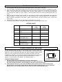
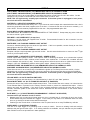
CS-882 OEM
ALARM UPGRADE FOR
FACTORY REMOTE KEYLESS ENTRY SYSTEM
INSTALLATION PRECAUTIONS & WARNINGS
NOTE: This system does not improve or affect the range of the factory remote keyless entry transmitters.
This is an ADD-ON system only. The arm/disarm range of this system will be identical to that of the
Factory Keyless’ Lock/Unlock range.
BEFORE BEGINNING, check all vehicle manufacturer cautions and warnings regarding electrical service (AIR
BAGS, ABS BRAKES, AND BATTERY).
DO NOT ROUTE ANY WIRING THAT MAY BECOME ENTANGLED with brake, and gas pedals, steering column,
or any other moving parts in the vehicle.
SUGGESTED COMPONENT MOUNTING
CONTROL MODULE: Underdash Mounting: If you are locating the control unit underdash, conceal module away
from any intruders. DO NOT Mount the control unit or wiring harness where they can become entangled with
moving parts such as brake/gas/clutch pedals, or the steering column.
LED: Mount the red LED in a visible location on the dashboard or console.
Shock Sensor: Mount the included shock sensor with wire ties to an under dash wire harness or fasten to a panel.
Disarm/Program Button: Mount the Override/Program push-button in a hidden location easily accessible to the
user in case the system must be disarmed without the use of the transmitter. This switch is also used to program
certain features.
SIREN (Not included): If you use a siren with your system, we recommend mounting it under the hood to an inner
fender-well or other body surface with the open end facing downward. Be sure the WHITE/RED wire is
programmed for siren output. See programming option #5.
TECH SUPPORT
Mon-Fri 8:00 AM-4:30 PM Pacific Time
(800) 998-6880
OPERATION
ARMING
To arm the alarm and lock the doors, press the Lock button of your Factory Keyless Remote Control. The 882
OEM system will sense the Door Lock signal and Arm. The lights will flash once, the vehicle horn or siren will chirp
once. After 3 seconds, the LED indicator will begin flashing slowly and Immobilizer circuits become active. This
system is now armed and ready to protect the vehicle.
ALARM TRIGGERING:
If there is an intrusion into the vehicle or hard impact to the body the alarm will sound which consists of flashing
lights and siren or pulsing car horn for 30 seconds. After the 30 second alarm cycle duration the system will stop,
but is still armed. LED will begin flashing rapidly indicating the alarm has been triggered.
DISARMING:
To disarm the CS-882 OEM, press the Unlock button of your Factory Keyless Remote. The CS-882 OEM system
will sense the Door Unlock signal and Disarm. The lights will flash twice and the vehicle horn or siren will chirp
twice. The LED will stop flashing. If the system was tripped in your absence, then the siren or horn will chirp 4
times and the lights will flash 4 times. If your hear 4 chirps/flashes, we recommend inspecting your vehicle for a
theft attempt or damage.
OPERATION
PASSIVE ARMING MODE (Programmable Option)
When programmed for Passive (Automatic Last Door Arming) the CS-882 will arm itself 30 Seconds after the
ignition is turned off and the last door has been closed. If a door is reopened, the system will wait for the door to
close before arming.
DUAL-STAGE SHOCK PROTECTION
If a low-level shock to the vehicle body is detected, the pre-warning sensor activates sounding 1 siren/horn chirp
and one light flash. If a hard impact to the vehicle occurs, the system will trigger for 30 seconds. Adjust the shock
sensor as needed by turning the control knob clockwise to increase sensitivity and counter-clockwise to decrease
sensitivity.
EMERGENCY OVERRIDE/DISARM
If the CS-882 system is armed and you have lost your Factory Keyless Remote or it stops working, you will have to
perform an emergency override. Enter your vehicle manually with the key, (this will trip the alarm) turn the Ignition
ON, and press override/program button 5 times within 8 seconds to disarm the system. The system will chirp/flash
4 times when disarmed.
PANIC MODE (Programmable Option)
To activate your system during an emergency situation or to attract attention to your vehicle, press the Lock button
on your remote 3 times within 5 seconds. This will activate a 30-second alarm trigger. Press any button on your
remote to disarm.
VALET MODE
To disable alarm functions of the 882 system, turn the Ignition ON and press the override/program button 3 times
within 8 seconds. After 8 seconds, the dash LED turns on solid as an indicator that the system is in valet mode.
Repeat this steps to exit VALET mode. The LED will go out, system will chirp (2) times and the light will flash (2)
times when exiting valet mode.
When in VALET mode the siren will still chirp for lock/unlock confirmation even though alarm functions are disabled.
The CS-882 system will chirp 2 times and flash the lights twice when locking the doors. The system will chirp 3
times and flash 3 times when unlocking the doors.
OPEN DOOR WARNING (Programmable Option)
If a door is open when the Ignition is on the 882 system will flash the parking lights for up to 1 minute or until the
door is closed as a “Door open” safety feature.
FACTORY TRUNK RELEASE SENSING
If the CS -882 system is installed in a vehicle with trunk pop or hatch release button on the Factory Remote, there is
a special input wire that will prevent the system from triggering if the trunk button on your remote is pressed while
the system is armed.
INSTALLATION – ARM/DISARM MODES (SWITCH SETTINGS)
ARM/ DISARM VALIDATION WITH NEGATIVE SIGNALS:
ARMING: To Arm the CS-882 OEM the system MUST sense a Negative
pulse on the GREEN/WHITE, validation wire when the vehicles. Door
LOCK Button is pressed.
DISARMING: To Disarm, the CS-882 OEM system MUST sense a
Negative pulse on the RE D/WHITE validation wire when the vehicles
Factory UNLOCK button is pressed. See switch setting at right. >>>
(TOP EDGE OF 882 MODULE)
ON
1 2 3 4
NEGATIVE VALIDATION INPUTS
ARM/ DISARM VALIDATION WITH POSITIVE SIGNALS:
Same as above, however the CS-882 system MUST sense Positive
signals for ARM/DISARM. See switch settings at right. >>>
(TOP EDGE OF 882 MODULE)
VALIDATION WIRES ON (MODE A = DIP SWITCHES 1-3 ON):
The Validation wires serve as a secondary input to prevent the system
from being armed or disarmed simply by pushing the unlock button on the
vehicle.
ON
1 2 3 4
POSITIVE VALIDATION INPUTS
PROGRAMMABLE OPTIONS
1.
2.
3.
4.
5.
6.
Turn the Ignition ON and press the Override/Program button 7 times within 10 seconds.
Turn OFF Ignition. LED will flash slowly once per second as and indicator the system is in programming mode.
Within 20 seconds, press the Override/Program button the number of times that corresponds to the feature list
below. The siren will chirp for each button press. DO NOT LOSE COUNT!! If you can hold down the button
for 3 seconds and release you get 2 chirps. A 3-second button press is the same as pressing the button 10
times.
When you get to the desired option number, turn the Ignition from OFF to ON to toggle between the preset and
alternate settings. The siren will chirp once or twice indication which value the feature is at. See Below for
Option numbers, descriptions, and values. Ignition should be left in the OFF position once your have the
correct value.
At this time, if you need to change more options, repeat steps 3 & 4 above.
To exit programming Mode, Turn Ignition ON and press the Override/Program button once.
OPTIONS CHART
Option #
Option Description
PRE-SET
Value
(1 chirp)
ON
ALTERNATE
Value
(2 chirps)
OFF
1
Flashing Lights
3
ON
OFF
6
Door Open Warning
Flash
Siren Chirps
ON
OFF
8
Passive Arming
OFF
ON
10
Door Trigger Input
Polarity (Blue wire)
NEGATIVE
14
15
Allow Panic Mode
Horn or Siren output
(White/Red wire)
Restore all options to
PRE SET VALUES
ON
HORN
25
POSITIVE
OFF
SIREN
YES
CURRENT SENSING (DIP SWITCH #4)
The CS -882OEM system includes a current sensing circuit to monitor current flow
through the vehicles electrical system. If and intruder opens a door and the interior
lights turn on the CS-882 system will detect this drain and trigger the alarm without
having to connect (Hardwire) this system to the interior dome light circuit and
hood/trunk pin switches. If your vehicle includes courtesy lights in the trunk and/or
under the hood, the system should also protect those areas when in current
sensing. Current sensor is off by default. See diagram at right >>.
DIP SWITCH #4
OFF
ON
4
CURRENT SENSING NOTES:
CURRENT SENSING
1. Current sensing may be a problem for you if your vehicle has a
thermostatically controlled fan system that may turn on after you have set
the alarm and left the vehicle. The fan turning on will cause a false alarm trigger.
2. Some vehicles with large or more then one battery will not operate well in current sensing mode
because there is not enough voltage drop for the unit to detect a light turning on. If you experience
problem with current sensing, please use the hard-wired door and hood/trunk inputs.
WIRING
VIOLET WIRE: ON-BOARD RELAY (10A) IMMOBILIZER CIRCUIT #1 NORMALLY OPEN
VIOLET WIRE: ON-BOARD RELAY (10A) IMMOBILIZER CIRCUIT #1 NORMALLY OPEN
These wires the are for an on board Relay to immobilize the Ignition or Fuel Pump Circuit in the vehicle. Cut the
selected circuit you want to immobilize and connect each end to a VIOLET wire.
NOTE: This is a high-security, normally open connection. If the alarm system is unplugged or loses power,
the circuit will still be immobilized!
WHITE/RED: (-) NEGATIVE HORN/SIREN OUTPUT
Connect to wire that activates the factory horn. If you choose to use this output with a standard alarm siren, then it
should be connected to the black (negative) wire of the siren. Connect the red wire of the siren to constant (+) 12
Volts. NOTE: This wire must be programmed for siren use. See programmable option #15.
BLACK WIRE: SYSTEM CHASSIS GROUND
THIS WIRE MUST BE CONNECTED TO CHASSIS METAL OF THE VEHICLE. Scrape away any paint or dirt from
the area to ensure a good connection.
RED WIRE: +12V POWER INPUT (15 amp fuse)
Connect to +12 Volt source with supplied fuse & holder. Recommended location for this connection is at the
vehicle battery positive terminal.
WHITE WIRE: +12V FLASHING PARKING LIGHT OUTPUT
Connect to switched parking light wire at back of light switch. If this is not possible, connect directly to one of the
parking lights at the front of the vehicle.
WHITE WIRE: +12V FLASHING PARKING LIGHT OUTPUT
nd
European vehicles require separate right and left circuits. Use this second white wire to connect to the 2 light
circuit on your European vehicle.
ORANGE WIRE: (-) NEGATIVE STARTER DISABLE / ARMED OUTPUT
Ground output when system is armed. This output is used for disabling the starter or to activate other optional
devices such as scanner LED’s, window control modules, voice modules etc. For starter kill, cut starter wire and
connect between 87A and 30 on relay. Connect orange wire to 85 and connect 86 to an Ignition source that has
voltage in “ON” and “CRANKING” positions at the Ignition switch. (Starter kill relay not included)
PINK/WHITE WIRE: ON-BOARD RELAY (10A) IMMOBILIZER CIRCUIT #2 NORMALLY OPEN
PINK WIRE: ON-BOARD RELAY (10A) IMMOBILIZER CIRCUIT #2 NORMALLY OPEN
These wires the are for an on board relay to immobilize the Ignition or Fuel Pump Circuit in the vehicle. Cut the
selected circuit you want to immobilize and connect one end to the Pink wire and the other end to the Pink/White.
NOTE: This is a high-security, normally open connection. If the alarm system is unplugged or loses power,
the circuit will still be immobilized!
YELLOW WIRE: +12 VOLTS IGNITION SWITCHED
Connect to an Ignition wire that shows +12 Volts with the key in both “On” and “Start” positions.
BLACK/WHITE WIRE: +12 VOLTS TRUNK RELASE INPUT (IF EQUIPPED)
Connect this wire to the positive trunk release solenoid wire. This will allow the unit to sense +12 Volts when the
Trunk Release Button is pressed on the Factory Remote Control to prevent an unwanted false alarm. Current
sensing and trunk are bypassed. If the trunk is then re-closed (sensed by trunk pin) the zone will re-arm in 3
seconds, otherwise system is still armed and must be disarmed with the Unlock Button on the remote before
entering vehicle.
BLUE WIRE: (-) or (+) DOOR TRIGGER (PROGRAMMABLE – DEFAULT IS NEGATIVE)
Connect to door pin activation circuit in vehicle.
• Negative type door circuits show Ground when any door is opened and 12 volts when all doors are closed.
Some vehicles may have isolated door triggers. In this case you may need to run additional wires from other
doors or go directly to the wire at the vehicle’s dome light.
• Positive type door circuits show 12 Volts when a door is opened such as on many Ford/Mercury vehicles.
GREEN WIRE: (-) HOOD/TRUNK TRIGGER
This wire is an input trigger for a grounding hood or trunk pin switch. Connect to existing hood and trunk pin
switches that read ground when open. If no existing switches are available, new pin switches may be installed.
Note: DO NOT mount new pin switches in water pathways.
WIRING
RED/WHITE: (+/-) Door Unlock Validation Signal INPUT: [Default Setting is Negative]
Connect to Vehicle’s Door Unlock Switch wire. NOTE: The module must be programmed for the correct signal
polarity. Prevents system from being disarmed simply by pressing the vehicle’s unlock button at the door panel.
GREEN/WHITE: (+/-) Door Lock Validation Signal INPUT: [Default setting is Negative]
Connect to Vehicle’s Door Lock Switch wire. NOTE: The module must be programmed for the correct signal
polarity. Prevents system from being disarmed simply by pressing the vehicle’s unlock button at the door panel.
BLUE/BLACK: Door Unlock Signal INPUT:
Connect to Vehicle’s (+12V ) Door Unlock (Solenoid/Motor) Wire.
YELLOW/BLACK: Door Lock Signal INPUT:
Connect to Vehicle’s (+12V ) Door Lock (Solenoid/Motor) Wire.
WIRING: MINI PLUGS
2-PIN PLUG (WHITE): PROGRAM/OVERRIDE PUSH BUTTON
2-PIN PLUG (RED): LED INDICATOR (RED FLASHING LIGHT)
3 PIN SENSOR PLUG: ,
WHITE Wire: Negative Signal
BLACK Wire: Sensor Ground
RED Wire Sensor +12V Power
SHOCK SENSOR: The sensor supplied with
this system does not require any additional
wiring. Simply mount the sensor in a suitable
location, plug it in, and adjust the sensitivity.
CS-882 OEM PARTS BAG
The enclosed diodes and resistors are only used for alternative installations that DO NOT use a Factory Remote
Transmitter to operate. This type of system locks and unlocks all doors when the vehicle key is turned in the
driver’s door.
Connect components as follows:
Yellow/Black: wire from CS882 connects to one side of resistor.
Remaining side of resistor connects to band end of diode.
Non-band end of diode (anode) connects to parking light switched +12 volt wire.
nd
Blue/Black: wire from CS882 connects to one end of 2 resistor.
nd
Remaining side of resistor connects to band end of 2 diode.
Non-band end of diode (anode) connects to door lock solenoid switch that switches from ground to +12 volts when
locking and unlocking.