1
THE SERVSWITCH™ FAMILY
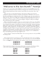
Welcome to the ServSwitchTM Family!
Thank you for purchasing a BLACK BOX® ServSwitch™ Brand KVM switch! We
appreciate your business, and we think you’ll appreciate the many ways that your
new ServSwitch keyboard/video/mouse switch will save you money, time, and
effort.
That’s because our ServSwitch family is all about breaking away from the
traditional, expensive model of computer management. You know, the one-sizefits-all-even-if-it-doesn’t model that says, “One computer gets one user station, no
more, no less.” Why not a single user station (monitor, keyboard, and mouse) for
multiple computers—even computers of different platforms? Why not a pair of
user stations, each of which can control multiple computers? Why not multiple
user stations for the same computer?
With our ServSwitch products, there’s no reason why not. We carry a broad line
of robust solutions for all these applications. Do you have just two PCs, and need
an economical alternative to keeping two monitors, keyboards, and mice on your
desk? Or do you need to share dozens of computers, including a mix of IBM® PC,
RS/6000®, Apple® Macintosh®, Sun Microsystems®, and SGI® compatibles among
multiple users with different access levels? Does your switch have to sit solidly on a
worktable and use regular everyday cables? Or does it have to be mounted in an
equipment rack and use convenient many-to-one cables? No matter how large or
small your setup is, no matter how simple or how complex, we’re confident we
have a ServSwitch system that’s just right for you.
The ServSwitch™ family from Black Box—the one-stop answer for all your KVMswitching needs!
*
This manual will tell you all about your new ServSwitch™ Ultra unit, including
how to install, operate, and troubleshoot it. For an introduction to the ServSwitch
Ultra, see Chapter 2. The ServSwitch Ultra product codes covered in this manual are:
KV5002MA-R2
KV5004SA-R2
KV5008SA-R2
KV5008FA-R2
KV5012FA-R2
KV5016FA-R2
This manual also includes information about the accessories with these product
codes (each comes with its own installation guide if ordered separately):
KV5000C
RMK19M
RMK19S
RMK19F
RMK23M
RMK23S
RMK23F
RMK24M
RMK24S
RMK24F
1
SERVSWITCH™ ULTRA
TRADEMARKS USED IN THIS MANUAL
BLACK BOX and the
logo are registered trademarks, ServSwitch, ServSwitch
Ultra, Matrix ServSwitch, and ServManager are trademarks, of Black Box
Corporation.
Apple, Mac, and Macintosh are registered trademarks, and Apple Desktop Bus and
ADB are trademarks, of Apple Computer, Inc.
ProComm is a registered trademark of DATASTORM TECHNOLOGIES, INC.™
Compaq and Alpha are registered trademarks, and DEC is a trademark, of
Compaq Computer Corporation.
HP is a registered trademark of Hewlett-Packard.
IBM, PC/AT, PS/2, RS/6000, and ThinkPad are registered trademarks, and
PC/XT is a trademark, of International Business Machines Corporation.
Helvetica and Times are registered trademarks of Linotype Company.
Logitech is a trademark of Logitech, Inc.
Microsoft, Windows, HyperTerminal, and IntelliMouse are trademarks or
registered trademarks of Microsoft Corporation in the United States and/or
other countries.
SGI is a registered trademark of Silicon Graphics, Inc.
Sony is a registered trademark of Sony Corporation.
Sun and Sun Microsystems are registered trademarks of Sun Microsystems, Inc. in
the United States and other countries.
UL is a registered trademark of Underwriters Laboratories, Inc.
UNIX is a registered trademark of UNIX System Laboratories, Inc.
Any other trademarks mentioned in this manual are acknowledged to be the property of the
trademark owners.
2
FCC/IC STATEMENTS
FEDERAL COMMUNICATIONS COMMISSION AND INDUSTRY CANADA
RADIO-FREQUENCY INTERFERENCE STATEMENTS
This equipment generates, uses, and can radiate radio frequency energy and if not
installed and used properly, that is, in strict accordance with the manufacturer’s
instructions, may cause interference to radio communication. It has been tested
and found to comply with the limits for a Class A computing device in accordance
with the specifications in Subpart J of Part 15 of FCC rules, which are designed to
provide reasonable protection against such interference when the equipment is
operated in a commercial environment. Operation of this equipment in a
residential area is likely to cause interference, in which case the user at his own
expense will be required to take whatever measures may be necessary to correct the
interference.
Changes or modifications not expressly approved by the party responsible for
compliance could void the user’s authority to operate the equipment.
This digital apparatus does not exceed the Class A limits for radio noise emission from digital
apparatus set out in the Radio Interference Regulation of Industry Canada.
Le présent appareil numérique n’émet pas de bruits radioélectriques dépassant les limites
applicables aux appareils numériques de la classe A prescrites dans le Règlement sur le
brouillage radioélectrique publié par Industrie Canada.
3
SERVSWITCH™ ULTRA
NORMAS OFICIALES MEXICANAS (NOM)
ELECTRICAL SAFETY STATEMENT
INSTRUCCIONES DE SEGURIDAD
1. Todas las instrucciones de seguridad y operación deberán ser leídas antes de
que el aparato eléctrico sea operado.
2. Las instrucciones de seguridad y operación deberán ser guardadas para
referencia futura.
3. Todas las advertencias en el aparato eléctrico y en sus instrucciones de
operación deben ser respetadas.
4. Todas las instrucciones de operación y uso deben ser seguidas.
5. El aparato eléctrico no deberá ser usado cerca del agua—por ejemplo, cerca
de la tina de baño, lavabo, sótano mojado o cerca de una alberca, etc..
6. El aparato eléctrico debe ser usado únicamente con carritos o pedestales que
sean recomendados por el fabricante.
7. El aparato eléctrico debe ser montado a la pared o al techo sólo como sea
recomendado por el fabricante.
8. Servicio—El usuario no debe intentar dar servicio al equipo eléctrico más allá
a lo descrito en las instrucciones de operación. Todo otro servicio deberá ser
referido a personal de servicio calificado.
9. El aparato eléctrico debe ser situado de tal manera que su posición no
interfiera su uso. La colocación del aparato eléctrico sobre una cama, sofá,
alfombra o superficie similar puede bloquea la ventilación, no se debe colocar
en libreros o gabinetes que impidan el flujo de aire por los orificios de
ventilación.
10. El equipo eléctrico deber ser situado fuera del alcance de fuentes de calor
como radiadores, registros de calor, estufas u otros aparatos (incluyendo
amplificadores) que producen calor.
11. El aparato eléctrico deberá ser connectado a una fuente de poder sólo del
tipo descrito en el instructivo de operación, o como se indique en el aparato.
4
NOM STATEMENT
12. Precaución debe ser tomada de tal manera que la tierra fisica y la polarización
del equipo no sea eliminada.
13. Los cables de la fuente de poder deben ser guiados de tal manera que no
sean pisados ni pellizcados por objetos colocados sobre o contra ellos,
poniendo particular atención a los contactos y receptáculos donde salen del
aparato.
14. El equipo eléctrico debe ser limpiado únicamente de acuerdo a las
recomendaciones del fabricante.
15. En caso de existir, una antena externa deberá ser localizada lejos de las lineas
de energia.
16. El cable de corriente deberá ser desconectado del cuando el equipo no sea
usado por un largo periodo de tiempo.
17. Cuidado debe ser tomado de tal manera que objectos liquidos no sean
derramados sobre la cubierta u orificios de ventilación.
18. Servicio por personal calificado deberá ser provisto cuando:
A: El cable de poder o el contacto ha sido dañado; u
B: Objectos han caído o líquido ha sido derramado dentro del aparato; o
C: El aparato ha sido expuesto a la lluvia; o
D: El aparato parece no operar normalmente o muestra un cambio en su
desempeño; o
E: El aparato ha sido tirado o su cubierta ha sido dañada.
5
SERVSWITCH™ ULTRA
Contents
Chapter
Page
1.
Specifications ........................................................................................... 10
2.
Introduction .............................................................................................
2.1 The Complete Package .....................................................................
2.2 Operating Features ...........................................................................
2.3 The Front Panel ................................................................................
2.4 The Rear Panel ..................................................................................
2.5 Cable Requirements .........................................................................
2.6 Equipment Requirements ................................................................
14
14
14
16
18
20
20
3.
Installation ................................................................................................
3.1 Quick Setup Guide ...........................................................................
3.2 Installation Procedure ......................................................................
3.2.1 Rackmounting (Optional) ....................................................
3.2.2 Connecting the Keyboard, Monitor, and Mouse ................
3.2.3 Connecting CPUs ..................................................................
3.2.4 Connecting Submasters (Optional) .....................................
3.2.5 Powering Up the System .......................................................
3.2.5.A Initial Steps ..............................................................
3.2.5.B Remaining Steps If All CPUs Are Sun Models .......
3.2.5.C Remaining Steps If Any CPUs Aren’t Sun Models ...
3.2.6 Changing the Keyboard Setting of Windows NT 4.0 CPUs ...
3.2.7 Switching from the Keyboard ...............................................
3.3 Cascading in ServSwitch Systems .....................................................
3.3.1 Cable Requirements for Expansion .....................................
3.3.2 Installing a Cascade ...............................................................
21
21
22
22
22
23
24
25
25
25
26
27
27
28
29
29
4.
Operation: Hardware and Keyboard Commands ..................................
4.1 Guidelines for Using the ServSwitch Ultra with Your Equipment ...
4.1.1 CPUs .......................................................................................
4.1.2 Mouse and Keyboard ............................................................
4.1.3 Monitor ..................................................................................
4.2 Keyboard-Command Summary ........................................................
4.3 The Commands in Detail .................................................................
4.3.1 Selecting a Port from the Shared Keyboard .........................
4.3.2 Switching to the Next or Previous Port ................................
4.3.3 Scan Mode .............................................................................
4.3.4 Keep Settings .........................................................................
4.3.5 Set Screen-Saver Interval ......................................................
4.3.6 Transpose Command and Alt Keys ......................................
4.3.7 Reset .......................................................................................
4.3.8 Send Null Byte (PS/2 Type Mice Only) ..............................
34
34
34
35
38
41
43
43
43
44
44
44
45
45
46
6
TABLE OF CONTENTS
Chapter
4.
5.
Page
Operation: Hardware and Commands (continued)
4.3 The Commands in Detail (continued)
4.3.9 Identify ROM .........................................................................
4.3.10 Send [Stop] ...........................................................................
4.3.11 Display Label .........................................................................
4.3.12 Activate On-Screen Menus ...................................................
4.3.13 Activate Select Window .........................................................
4.3.14 Log Out ..................................................................................
4.4 Using the RS-232 Port .......................................................................
4.4.1 Connecting Equipment to the Port .....................................
4.4.2 Switching Ports Remotely (Optional) ..................................
4.4.3 Upgrading the Firmware (Flash Memory) ..........................
4.4.3.A Upgrading the Firmware with
Terminal-Emulation Software .............................
4.4.3.B Upgrading the Firmware with
the DOS COPY Command .................................
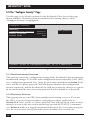
Operation: On-Screen Display ................................................................
5.1 Overview ............................................................................................
5.1.1 The Main Menu .....................................................................
5.1.2 Navigating the Configuration Pages ....................................
5.1.3 Saving Changes Made with the On-Screen Display .............
5.2 The “Configure System” Page ..........................................................
5.2.1 Configure System: Keyboard ................................................
5.2.2 Configure System: Mouse .....................................................
5.2.3 Configure System: Maximum Computers ...........................
5.2.4 Configure System: Expansion Units ....................................
5.2.5 Configure System: Expansion Width ...................................
5.2.6 Configure System: Scan Mode ..............................................
5.2.7 Configure System: Scan Time ..............................................
5.2.8 Configure System: Power-On Scan .......................................
5.2.9 Configure System: Typematic Rate .......................................
5.2.10 Configure System: Typematic Delay ....................................
5.3 The “Configure Computers” Page ...................................................
5.3.1 Configure Computers: Computer Name .............................
5.3.2 Configure Computers: Keyboard .........................................
5.3.3 Configure Computers: Mouse ..............................................
5.4 The “Configure Overlay” Page .........................................................
5.4.1 Configure Overlay: Miscellaneous .......................................
5.4.1.A Color Scheme ..........................................................
5.4.1.B Resolution ................................................................
5.4.1.C Screen Saver .............................................................
5.4.1.D Screen-Saver Time ...................................................
47
47
47
48
48
48
49
49
50
51
51
54
56
56
56
57
57
58
58
59
61
62
62
63
63
63
63
64
65
66
67
68
69
69
69
70
70
71
7
SERVSWITCH™ ULTRA
Contents (continued)
Chapter
5.
6.
8
Page
Operation: On-Screen Display (continued)
5.4 The “Configure Overlay” Page (continued)
5.4.2 Configure Overlay: Computer Select Window ....................
5.4.2.A Background Color and Text Color ........................
5.4.2.B Position .....................................................................
5.4.3 Configure Overlay: Computer Label ...................................
5.4.3.A Background Color and Text Color ........................
5.4.3.B Position .....................................................................
5.4.3.C Show Computer Number ........................................
5.4.3.D Fade Out ..................................................................
5.4.3.E Font ...........................................................................
5.5 The “Configure Security” Page ........................................................
5.5.1 The Configuration Password ................................................
5.5.2 The Access Password .............................................................
5.5.3 The Access Timeout ..............................................................
5.5.4 Setting the Passwords ............................................................
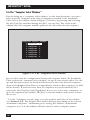
5.6 The “Computer Select Window” ......................................................
71
71
71
72
72
72
72
73
73
74
74
74
75
75
76
Troubleshooting ...................................................................................... 77
6.1 Restoring Factory-Default Settings ................................................... 77
6.2 Common Problems ........................................................................... 78
6.2.1 CPU Doesn’t Boot ................................................................. 78
6.2.2 Can’t Switch Ports from Keyboard ....................................... 79
6.2.3 Typed Characters Wrong or Missing ................................... 79
6.2.4 Can’t Switch or Scan to Certain Ports .................................. 79
6.2.5 ServSwitch Ultra Scans or Switches to Empty Ports ............ 80
6.2.6 Mouse Driver Doesn’t Load (IBM PC Type Mice Only) .... 80
6.2.7 Can’t Access Mouse Functions (IBM PC Type
Mice Only) .......................................................................... 80
6.2.8 PS/2 Mouse Gets Out of Sync .............................................. 80
6.2.9 Mouse Doesn’t Move Pointer/Cursor ................................. 81
6.2.10 Display is Fuzzy ...................................................................... 81
6.2.11 Video Not Synchronized or Wrong Color ........................... 81
6.2.12 Can’t Access High-Resolution Mode .................................... 82
6.2.13 On-Screen Display Not Synchronized .................................. 82
6.2.14 CPUs Lock Up When Windows 3.x Loaded ........................ 82
6.2.15 ServSwitch Ultra Doesn’t Work with Docking Station ........ 82
6.2.17 ServSwitch Ultra Doesn’t Work with
Dongle-Protected Software ................................................ 83
6.2.18 ServSwitch Ultra Doesn’t Work with IBM ThinkPad .......... 83
6.2.19 Lost Password ............................................................................83
6.3 Calling Black Box .............................................................................. 84
6.4 Shipping and Packaging .................................................................. 84
TABLE OF CONTENTS
Appendix
Page
Appendix A: NVRAM Factory Defaults ......................................................... 85
A.1 Keyboard-Command Settings ........................................................... 85
A.2 On-Screen Configuration Settings ................................................... 86
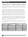
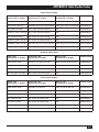
Appendix B: Cable Product Codes ................................................................ 88
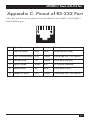
Appendix C: Pinout of RS-232 Port ............................................................... 91
Appendix D: The LK461 Keyboard ............................................................... 92
Appendix E: Rackmounting Your ServSwitch Ultra ..................................... 93
9
SERVSWITCH™ ULTRA
1. Specifications
Hardware
Required —
Monitor that supports your computers’ highest video
standard; in multiplatform applications, should be a
multisync model capable of forming video from either
composite sync or separate horizontal and vertical sync
signals (see Section 4.1.1)
Compliance —
CE, FCC Part 15 Subpart J Class A, IC Class/classe A
Standards —
With original Serv cabling: VGA (color or monochrome/
page white) video;
With original Serv cabling (minimal) or coaxial cabling
(recommended): SVGA and Mac video;
With coaxial cabling: XGA (color or monochrome), Sun,
RS/6000, and SGI video
Interfaces —
RS-232 port: EIA/TIA RS-232 proprietarily pinned on
RJ-12 (“6-wire RJ-11”) connector, DTE;
CPU and MONITOR/KEYBOARD/MOUSE ports:
Proprietary composite of:
• IBM AT, IBM PS/2, Sun, or ADB keyboard;
• RS-232, PS/2, Sun, or ADB mouse; and
• Video (standards listed above)
Resolution —
With original Serv cabling: Up to 1024 x 768
noninterlaced;
With coaxial cabling: Up to 1600 x 1280 noninterlaced;
Refer to Section 4.1.3
Refresh Rate —
Up to 100 Hz
Protocol —
RS-232: Asynchronous
Data Format —
RS-232: 8 data bits, 1 stop bit, no parity (fixed)
Data Rate —
RS-232: 9600 or (for firmware update only) 57,600 bps
10
CHAPTER 1: Specifications
Maximum
Distance —
Depending on the CPU, monitor, and video resolution
(see Section 4.1.3), either:
20 ft. (6.1 m) of original Serv cable from any
ServSwitch Ultra to any device attached to it, with
not more than 40 ft. (12.2 m) of total original Serv
cable between any CPU and any user station; or
20 ft. (6.1 m) of coaxial cable—possibly as much as
100 ft. (30.5 m), depending on CPUs—from any
ServSwitch Ultra to any device attached to it;
Also, 50 ft. (15.2 m) of serial cable from the RS-232 port
of any ServSwitch Ultra to a computer’s serial port
User Controls —
All models:
Keyboard commands;
On-screen menus;
KV5002MA-R2:
(3) Front-mounted pushbuttons:
“ON/OFF” (power), “+” (switch to next port), and
“–” (switch to previous port);
All models except KV5002MA-R2:
(2) Front-mounted pushbuttons:
“” (switch to next port) and “” (switch to
previous port);
(1) Rear-mounted rocker switch for power
Indicators —
All front-mounted LEDs;
All models: (1) for ServSwitch Ultra unit: POWER;
KV5002MA-R2: (4) for CPUs: (2) SELECT, (2) POWER;
KV5004SA-R2: (8) for CPUs: (4) SELECT, (4) POWER;
KV5008SA-R2, KV5008FA-R2:
(16) for CPUs: (8) SELECT, (8) POWER;
KV5012FA-R2: (24) for CPUs: (12) SELECT,
(12) POWER;
KV5016FA-R2: (32) for CPUs: (16) SELECT,
(16) POWER
11
SERVSWITCH™ ULTRA
Connectors —
All rear-mounted;
(1) RJ-12 (“6-wire RJ-11”) female: RS-232;
(1) DB25 female: MONITOR/KEYBOARD/MOUSE;
(1) Power inlet:
KV5002MA-R2: 5-pin DIN female;
All other models: IEC 320 male;
DB25 female CPU ports:
KV5002MA-R2: (2);
KV5004SA-R2: (4);
KV5008SA-R2, KV5008FA-R2: (8);
KV5012FA-R2: (12);
KV5016FA-R2: (16)
Power —
KV5002MA-R2:
From wallmount external power supply (type may vary,
refer to labeling on transformer):
Either:
Input: 90 to 260 VAC at 50 or 60 Hz, 65 to 130 mA;
Output: +8 VDC at 1.5 A, –8 VDC at 375 mA;
or:
Input: 90 to 264 VAC at 47 to 63 Hz, 78 to 156 mA;
Output: +12 VDC at 1 A, –12 VDC at 0.5 A;
Consumption: Up to 15 VA (15 watts);
All other models;
From AC outlet through included power cord and
IEC 320 male inlet to UL®, CUL, and TÜV approved
internal transformer:
Input: 100 to 240 VAC at 50 or 60 Hz, 450 mA;
Output: +5 VDC at 1.5 A, +12 VDC at 1 A;
Consumption: Up to 19.5 VA (19.5 watts)
Maximum
Altitude—
10,000 ft. (3048 m)
Temperature
Tolerance—
32 to 131˚F (0 to 55˚C)
Humidity
Tolerance—
5 to 80% noncondensing
Enclosure —
Steel
12
CHAPTER 1: Specifications
Size —
KV5002MA-R2:
1.8" (1U) H x 8.8"W x 4.8"D (4.5 x 22.5 x 12.4 cm);
KV5004SA-R2, KV5008SA-R2:
1.8" (1U) H x 16.8"W x 4.8"D (4.5 x 42.5 x 12.4 cm);
KV5008FA-R2, KV5012FA-R2, KV5016FA-R2:
3.5" (2U) H x 16.8"W x 4.8"D (8.9 x 42.5 x 12.4 cm)
Weight —
KV5002MA-R2: 2 lb. (0.9 kg);
KV5004SA-R2: 3 lb. (1.4 kg);
KV5008SA-R2: 4 lb. (1.8 kg);
KV5008FA-R2: 5 lb. (2.3 kg);
KV5012FA-R2, KV5016FA-R2: 6 lb. (2.7 kg)
13
SERVSWITCH™ ULTRA
2. Introduction
Thank you for choosing a ServSwitch Ultra™. Designed with your needs in mind,
your new Switch will simplify your job by helping you organize your multiplecomputer application. With your Switch, you can use one keyboard, monitor, and
mouse to access a number of computers compatible with any of a number of
hardware platforms—including IBM® PC and RS/6000®, Apple® Macintosh®, Sun
Microsystems®, and SGI®—so you can significantly reduce your equipment
overhead and end keyboard and monitor clutter.
This chapter describes everything that comes with the Switch, the external and
operating features of the Switch, and the cabling you’ll need for the Switch.
2.1 The Complete Package
Your ServSwitch Ultra package includes the Switch unit, its power supply, a
modular cable and adapter for connecting one of the unit’s RS-232 ports to a
remote PC, and this manual. If you didn’t receive everything, or if anything arrived
damaged, contact Black Box.
2.2 Operating Features
Some of the useful features of the ServSwitch Ultra:
• Microprocessor-controlled keyboard and mouse switching.
• On-screen menu system for configuration and operation.
• You can access up to 256 CPUs with one keyboard, monitor, and mouse. (This
would require the maximum cascaded system of seventeen 16-port Serv units.)
• You can select the desired CPU using the on-screen display, keyboard, front
panel, or RS-232 port.
• Front-panel LEDs show the selected CPU and its power-on state.
• Supports IBM PC and RS/6000, Apple® Macintosh®, and Sun Microsystems®
compatible computers, as well as current SGI compatible computers.
• Supports all modes of PS/2® and PC/AT® compatible keyboards, as well as
ADB® (Apple Desktop Bus®) and Sun® keyboards.
• Mouse can be PS/2®, Microsoft® serial, PC Mouse® (Mouse Systems®) serial,
serial 8-bit, ADB, or Sun type (although the mouse type must match the
keyboard type).
14
CHAPTER 2: Introduction
• Supports SVGA, color or monochrome XGA or VGA, Apple, Sun, RS/6000,
and SGI video at resolutions up to 1280 x 1024 noninterlaced (although all
video types except VGA and Apple low-res require coaxial or special
cables).Note that in a multiplatform environment, you will need a multisync
monitor capable of syncing to the output of all your CPUs’ video cards and of
supporting their highest resolutions; refer to Section 4.1. Also note that you’ll
need a Mac® Adapter for ServSwitch for each CPU that outputs Apple video at
resolutions over 640 x 480; see the Note on page 23.
• The units remember and restore Num Lock, Caps Lock, Scroll Lock, and
keyboard mode for each CPU.
• Screen-save function can turn off video after 1 to 999 seconds of inactivity.
• Scan function can sequence between CPUs every 1 to 15 seconds.
• You can program the keyboard’s typematic rate and delay.
• Custom settings for each CPU can be saved in nonvolatile memory.
• The units have flash memory, so you can upgrade their firmware through their
RS-232 ports.
• Rackmount kits are available.
• Full-size 8- and 12-port units can be expanded up to 16 ports by installing
4-Port Expansion Boards. Please contact Black Box Tech Support if you ever
want us to do this for you.
15
SERVSWITCH™ ULTRA
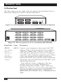
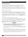
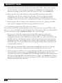
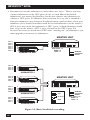
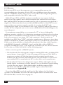
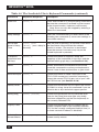
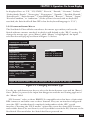
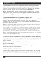
2.3 The Front Panel
The front panels of the ServSwitch Ultra feature two or three pushbutton switches
and several LED indicators. To familiarize yourself with these controls and
indicators, refer to Figures 2-1, 2-2, and 2-3 below and the descriptions that follow
on the next page.
ON/OFF
1
POWER
2
3
4
SELECT POWER SELECT POWER SELECT POWER SELECT POWER
Figure 2-1. The front panel of a KV5x04M model (mini)
4 to 1 ServSwitch Ultra.
Power
5
6
7
8
1
2
3
4
Figure 2-2. The front panel of a KV5x08S model (slimline)
8 to 1 ServSwitch Ultra.
Power
13
14
15
16
9
10
11
12
5
6
7
8
1
2
3
4
Figure 2-3. The front panel of a KV5x16F model (full-size)
16 to 1 ServSwitch Ultra.
16
CHAPTER 2: Introduction
Panel Label
Description
POWER (left)
Main Power LED: Lights to indicate that unit is powered ON.
ON/OFF
2-port units only: Press this button to turn the ServSwitch ON
or OFF.
[Numbered]
CPU Status LEDs: Numbered pairs of LEDs indicate the
status of the CPU or submaster (cascaded) Serv device
connected to the corresponding port on the rear panel:
SELECT or [unlabeled left] (red)
Lights if the corresponding port is the currently selected port.
POWER or [unlabeled right] (green)
Lights if the device on the corresponding port is powered ON.
NOTE
The mini-model chassis has 4 each of the Select and
[CPU] Power LED slots. The slimline-model chassis
has 8 each of these slots, and the full-size chassis has
16 each of them. The extra LED slots in the chassis of
the 2-port mini, 4-port slim, and the 8- and 12-port fullsize models are left blank, but are protected by
material mounted inside the chassis.
– or Previous Port Button: Press this button to manually switch the
shared monitor, keyboard, and mouse from the currently
selected computer to the previous one in sequence.
+ or Next Port Button: Press this button to manually switch the
shared monitor, keyboard, and mouse from the currently
selected computer to the next one in sequence.
17
SERVSWITCH™ ULTRA
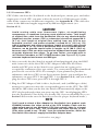
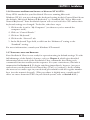
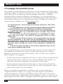
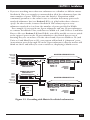
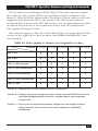
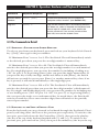
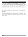
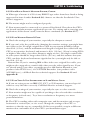
2.4 The Rear Panel
All cable connections are made at the rear panel of the ServSwitch Ultra, as
illustrated in Figures 2-4 and 2-5 and described below.
CPU3
CPU4
CPU1
CPU2
MONITOR/KEYBOARD/MOUSE
RS-232
POWER
17VAC CT
Figure 2-4. The rear panel of a 2 to 1 ServSwitch Ultra (KV5002MA-R2).
POWER
CPU 15
CPU 16
CPU 13
CPU 14
CPU 11
CPU 12
CPU 9
CPU 10
CPU 7
CPU 8
CPU 5
CPU 6
CPU 3
CPU 4
CPU 1
CPU 2
MONITOR/KEYBOARD/MOUSE
RS-232
Figure 2-5. The rear panel of a 16 to 1 ServSwitch (SW725A-R4).
Panel Label Conn.
CPU N
[N = a number
from 1 to
either 2, 4, 8,
12, or 16,
depending on
which model
you have]
18
Description
DB25 F Connect your computers to these ports with “CPU
Adapter Cables.” At the ServSwitch Ultra end these
cables have a DB25 male connector; at the other
ends, they have appropriate connectors to plug into
your CPUs’ video, keyboard, and mouse ports. These
cables take the signals that would normally pass
between the CPUs’ ports and the monitor, keyboard,
and mouse, and carry them between the CPUs’ ports
and the Switch instead.
You could also connect “submaster” Serv type
switches to these ports using “ServSwitch-toServSwitch Expansion Cables.” These cables have
DB25 male connectors at both ends; at the submaster
end, they should be plugged into a MONITOR/
KEYBOARD/MOUSE port. Refer to Sections 2.5 and
3.2.4.
CHAPTER 2: Introduction
Panel Label
Connector
or Control
Description
CPU N
DB25 F
For each submaster you plan to connect, you
must have an Expansion Cable; you must have
an Adapter Cable for each CPU you plan to
connect. See Section 2.5.
(continued)
NOTE
The 2-port (mini) chassis has 4 CPU N
connector slots; the slimline-model
chassis has 8 of these slots, and the
full-size chassis has 16 of them. The
extra connector slots in the chassis of
the 2-port, 4-port slim, and 8- and
12-port full-size models are left blank,
but are protected by material mounted
inside the chassis.
MONITOR/ DB25 F
KEYBOARD/
MOUSE
Connect the shared monitor, keyboard, and
mouse to this port using an “MKM Adapter
Cable.” At the ServSwitch Ultra end, this cable
has a DB25 male connector; at the other ends,
it has appropriate connectors to plug into your
monitor, keyboard, and mouse cables. Only one
MKM Adapter Cable is needed. See Section 2.5.
RJ-12 F
If you connect a more distant computer or
terminal to this RS-232 serial port, you’ll be able
to send switching commands to the ServSwitch
Ultra from a secondary location. You would also
connect a computer to this port to upgrade the
Switch’s firmware. Refer to Section 4.4.
RS-232
POWER
Rocker
[Switch], all
switch
except 2-port
POWER
[Inlet]
2-port:
5-pin
DIN M
Others:
IEC 320 M
Flipping this switch turns the ServSwitch Ultra
ON and OFF when the power cord is plugged
into the unit and into a working outlet.
Connect the ServSwitch Ultra’s power cord or
power-supply cord here. The power supply is
autosensing; it will accept input voltages from
90 to 264 VAC (2-port units [external
transformer]) or 100 to 240 VAC (other models
[internal transformer]).
19
SERVSWITCH™ ULTRA
2.5 Cable Requirements
Many switches of this type have what seems like ten million connectors on their
rear panels: one for each CPU’s video cable, one for each keyboard cable, and a
third for each mouse cable. The potential for tangling or mismatching cables is
high.
By contrast, you can connect the ServSwitch Ultra to your CPUs with one CPU
Cable (also called a “CPU Adapter Cable”) for each CPU. This single cable reaches
the CPU’s video-output, keyboard, and mouse ports.
Likewise, to connect “submaster” (slave) Serv type switches, you need one
“ServSwitch-to-ServSwitch Expansion Cable” for each subsidiary unit.
Lastly, you can connect the ServSwitch Ultra to the shared monitor, keyboard
and mouse with a single User Cable (also called an “MKM Adapter Cable”).
The exact variety or varieties of these cables that you’ll need will depend on the
equipment you are connecting for your application. Refer to Appendix B for the
available types of these cables and the corresponding product codes. Also refer to
Chapter 1 or the Caution notice on page 23 for information about maximum
cabling distances.
NOTES
SVGA (over longer distances), XGA, and high-resolution Mac video
place special demands on cabling that the regular CPU Cables and User
Cables typically cannot meet. For these applications, you should use
coaxial cables that can carry video signals not only farther but also at
higher resolutions. See Appendix B and the Caution notice on page 23.
You’ll also need a “Mac Adapter for ServSwitch” for each Mac CPU
outputting high-res (greater than 640 x 480) video; see the Note on
page 23.
2.6 Equipment Requirements
If the CPUs you will be controlling through your ServSwitch Ultra are not all of the
same type—especially if your CPUs represent completely different hardware
platforms (IBM, Mac, etc.)—you will have to be careful to choose a common
monitor, keyboard, and mouse that adequately support all of the CPUs. For full
details, see Section 4.1.
20
CHAPTER 3: Installation
3. Installation
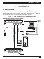
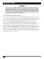
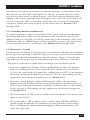
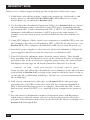
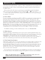
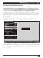
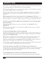
3.1 Quick Setup Guide
Figure 3-1, below, shows a basic example of connecting a CPU, a submaster, a
keyboard, a monitor, and a mouse to the ServSwitch unit. IBM PC equipment is
shown, but the basic principles will be similar for all equipment types. Connectors
will vary depending on the types of equipment you are installing.
Figure 3-1. Basic system setup for a slimline 8-port unit.
SLIMLINE 8-PORT SERVSWITCH ULTRA (KV5008SA-R2)
POWER
CPU 7
CPU 8
CPU 5
CPU 6
CPU 3
CPU 4
CPU 1
CPU 2
MONITOR/KEYBOARD/MOUSE
6-wire
modular
cable to
remote PC
RS-232
User Cable
CPU Cable
ServSwitch-to-ServSwitch Expansion Cable
Power
cord
Mouse
Keyboard
Monitor
To keybd port
To mouse port
To video port
POWER
CPU 7
CPU 8
CPU 5
CPU 6
CPU 3
CPU 4
CPU 1
CPU 2
MONITOR/KEYBOARD/MOUSE
RS-232
Slimline 8-Port ServSwitch
(KV3108SA-R4) submaster
21
SERVSWITCH™ ULTRA
3.2 Installation Procedure
This section provides complete instructions for the hardware setup of a single
ServSwitch Ultra. (For detailed instructions on the capabilities and concerns
involved in installing a cascaded Switch system, see Section 3.3; to make
troubleshooting the installation easier, we recommend that you check the master
and each submaster as it is installed, rather than installing all units, then checking
the entire cascade.) For an illustrated example of the elements of a basic setup, see
Figure 3-1 on the previous page.
3.2.1 RACKMOUNTING (OPTIONAL)
If you want to mount the ServSwitch Ultra in a rack, you will need a ServSwitch
Rackmounting Kit. For the 2-port mini model (KV5002MA-R2), our product code
for a 19", 23", or 24" Kit is RMK19M, RMK23M, or RMK24M respectively. For the
slimline models, our product code for a 19", 23", or 24" Kit is RMK19B, RMK23B,
or RMK24B respectively. For the full-size models, our product code for a 19", 23",
or 24" Kit is RMK19C, RMK23C, or RMK24C respectively. See Appendix E for more
information.
3.2.2 CONNECTING THE MONITOR, KEYBOARD, AND MOUSE
A User Cable (also called a Monitor/Keyboard/Mouse [“MKM”] Adapter Cable)
connects your monitor, keyboard, and mouse to the Switch. Because various styles
of electrical connectors are used by different classes of equipment, we supply this
cable in various styles to match (see Appendix B). This cable also comes in the
different lengths supported by different applications (see Section 4.1.3,
Appendix B, and the Caution notice on the next page).
CAUTION!
Make very sure that the monitor, keyboard, and mouse you plan to use
can meet the demands of your application—see Section 4.1. Also, note
that the ServSwitch Ultra doesn’t support keyboard-line dongles.
1. After you verify that the Switch is turned OFF, plug the DB25 male connector
of the User Cable into the port labeled MONITOR/KEYBOARD/MOUSE on
the Switch’s rear panel.
2. If your user-station equipment is IBM type, plug the cables from your shared
monitor, keyboard, and mouse into the corresponding connectors on the other
ends of the User Cable. If your equipment is Mac or Sun type, plug the mouse
cable into the keyboard, and plug the monitor and keyboard cables into the
corresponding connectors on the other ends of the User Cable.
22
CHAPTER 3: Installation
3.2.3 CONNECTING CPUS
CPU Cables run from the ServSwitch to the keyboard port, mouse port, and videooutput port of each CPU you want to directly attach to it. Different types of this
cable fit the connectors on different computers (see Appendix B). This cable also
comes in the different lengths supported by different applications (see
Section 4.1.3).
CAUTION!
Avoid routing cable near fluorescent lights, air-conditioning
compressors, or machines that may create electrical noise. Total length
of original Serv cable from the ServSwitch Ultra to any attached device
(keyboard, monitor, mouse, CPU, or submaster) should not exceed 20 ft.
(6.1 m); total length of original Serv cabling from any CPU to any
keyboard, monitor, and mouse shouldn’t exceed 40 ft. (12.2 m). For
typical equipment and video resolutions, length of coaxial cable should
not exceed 20 ft. (6.1 m) from a ServSwitch Ultra to any attached device.
However, we do provide coaxial cable in lengths up to 100 ft. (30.5 m),
because some CPUs can drive and receive keyboard and mouse signals
at greater distances than others. To go even farther, you might want to
use Station Extenders or CAT5 KVM Extenders (see Appendix B) if your
common keyboard and mouse are IBM type.
1. After you verify that the Switch is turned off and unplugged, plug the DB25
male connector of the first CPU’s CPU Adapter Cable into the lowestnumbered CPU port on the Switch’s rear panel that isn’t going to be
occupied by a submaster Serv type switch. Use consecutively higher-numbered
ports for the rest of the CPUs. For example, if you planned to put three
submasters and three CPUs on an 8-port master Switch, you would put the
submasters on ports CPU 1 through CPU 3 (see Section 3.2.4), and you would
plug the three CPUs into ports CPU 4 through CPU 6.
2. Plug the CPU Adapter Cable’s video-, keyboard-, and (on IBM type cables)
mouse-port connectors into the corresponding ports on the CPU. The CPU
should be OFF when you do this; the Switch will automatically adjust to the
CPU’s keyboard mode when you power up the CPU. Avoid plugging CPUs
into the ServSwitch Ultra if they are already ON; if you accidentally do so, see
Section 5.3.2 to make sure the Switch is set for the proper keyboard mode.)
NOTE
You’ll need to attach a Mac Adapter for ServSwitch (our product code
KV99MA) between the video strand of the CPU Adapter Cable and the
video-output port of any Macintosh CPU that outputs video in a format
other than VGA (640 x 480). This is because the video circuitry of Mac
CPUs often needs to see “ID bits” from the attached monitor, which the
ServSwitch Ultra doesn’t supply but the Mac Adapter does.
(continued on next page)
23
SERVSWITCH™ ULTRA
CAUTION!
Do not attach docking stations for older models of the ThinkPad® or
other portable computers to the ServSwitch Ultra. The Switch currently
supports only “stream mode” (continuous) mouse data, but older
ThinkPad models have to see “prompt mode” (burst-on-request) mouse
data. Some newer docking stations and some newer ThinkPad models
might work with the Switch, but determining whether a particular unit will
do so will probably require trial and error.
3.2.4 CONNECTING SUBMASTERS (OPTIONAL)
To connect a submaster Serv type switch (ServSwitch Ultra, regular ServSwitch,
etc.) to a master ServSwitch Ultra, run a ServSwitch-to-ServSwitch Expansion Cable
(our product code EHN055 for original cable or EHN274 for [recommended]
coaxial cable) from one of the master Switch’s CPU ports to (one of) the
submaster’s MONITOR/KEYBOARD/MOUSE port(s). Connect the first
submaster to the master Switch’s CPU 1 port and use consecutively highernumbered ports (CPU 2, CPU 3, and so on) for the rest of the submasters. If you
are connecting each of several submaster Matrix ServSwitches to two master
ServSwitch Ultras (see Section 3.3), connect the CPU ports of one master to the
submasters’ MONITOR/KEYBOARD/MOUSE A ports, and the CPU ports of the
other master to the submasters’ MONITOR/KEYBOARD/MOUSE B ports.
Before installing an advanced configuration, please call Black Box and discuss
your application with a technician.
24
CHAPTER 3: Installation
3.2.5 POWERING UP THE SYSTEM
3.2.5.A Initial Steps
1A. 2-port model (KV5002MA-R2): Making sure that the connected CPUs and any
connected submasters are OFF (powered down), take the output cord of the
ServSwitch Ultra’s power supply and plug its 5-pin DIN male connector into
the power jack on the rear panel of the Switch. Plug the power supply’s input
cord into a working outlet.
1B. Other models: Making sure that the connected CPUs and any connected
submasters are OFF (powered down), take the ServSwitch Ultra’s power cord
and plug its IEC 320 female connector into the power inlet on the rear panel
of the Switch. Plug its other end into a working outlet.
2. To power up the ServSwitch Ultra, push the ON/OFF button on its front
panel (if it’s a 2-port unit) or move the ON/OFF switch on its rear panel to the
“|” (ON) position (if it’s another type of unit). The Switch should boot
normally, but if the unit’s firmware has become corrupted—probably as the
result of a firmware upgrade going wrong—it will display this message on the
attached monitor:
Kernel is bad, load new kernel through serial port
If you see this, you will need to download correct firmware to the unit as
described in Section 4.4.3, starting at the point at which the unit is ready to
receive the file at 9600 baud (9600 bps). (In this case, you must download the
file at 9600 bps.)
3.2.5.B Remaining Steps If All CPUs Are Sun Models
If all of your CPUs are Sun models, you need to proceed with the steps in this section
in order to avoid video problems. If any of your CPUs are not Sun models, use the
alternative steps in Section 3.5.2.C on the next page.
3. Before you power up any CPUs, try to change the Switch’s keyboard output
on all of its CPU ports from IBM PS/2 type to Sun type. If your Switch’s
firmware is a recent enough version, a “universal Sun keyboard mode”
command will be active until you set a password for the Switch. Press and
release the [Control] key on your Sun keyboard, then type the letter [M]
followed by the numbers [5] and [0], then press and release [Enter]. This
should cause all of your CPU ports to switch to Sun keyboard-mode output.
Now use the Switch’s front-panel LEDs and pushbuttons to select one of
your Sun CPUs (see Section 2.3) and power up that CPU. It should boot
properly and output video. If it doesn’t, power it back down, unplug the
keyboard strand of the CPU cable from the CPU’s keyboard port, plug a Sun
keyboard into that keyboard port, and power the CPU back up; this will
definitely give you video. Once the CPU boots with video active, remove the
25
SERVSWITCH™ ULTRA
keyboard and reattach the keyboard strand of the CPU cable; you can now
use the Switch’s on-screen menu system (see Section 5.1) to change the
keyboard settings of the all of your CPU ports to “Sun” (see Section 5.3).
4. Power up the rest of the directly connected CPUs and any connected
submasters one by one, giving each one time to boot completely before
turning ON the next one. (Issue a Keep Settings command after initial
bootup, so that the Switch saves its keyboard settings to nonvolatile memory.)
5. Power up any CPUs connected to submasters one by one, giving each CPU
time to boot completely before turning ON the next one.
3.2.5.C Remaining Steps If Any CPUs Aren’t Sun Models
If not all of your CPUs are Sun models—that is, if at least one of your CPUs is a PC,
Mac, etc.—proceed with the steps in this section. If all of your CPUs are Sun models,
use the alternative steps in Section 3.5.2.B on the previous page.
3. Power up any directly connected non Sun CPUs and any connected
submasters one by one, giving each one time to boot completely before
turning ON the next one. When the non Sun CPUs are powered up after the
ServSwitch Ultra, the Switch emulates all keyboard and mouse functions for
automatic bootup. (You might want to issue a Keep Settings command after
initial bootup, so that the Switch saves the mode settings it has autodetected
to nonvolatile memory.)
4. Power up any non Sun CPUs connected to submasters one by one, giving
each CPU time to boot completely before turning ON the next one.
5. If there are any Sun CPUs in your system: Switch to a CPU port that has a powered
non Sun CPU attached to it (see Section 3.2.7). Bring up the Switch’s onscreen menu system (see Section 5.1) and change the keyboard settings of the
CPU ports with Sun CPUs attached to them to “Sun” (see Section 5.3). Power
up all of the Sun CPUs one by one, giving each CPU time to boot completely
before turning ON the next one.
26
CHAPTER 3: Installation
3.2.6 CHANGING THE KEYBOARD SETTING OF WINDOWS NT 4.0 CPUS
If any CPUs attached to your ServSwitch Ultra are running Microsoft
Windows NT 4.0, you must change the keyboard setting in their Control Panel from
the default, “Microsoft Enhanced Keyboard,” to “Standard 101/102 or Microsoft
Natural Keyboard.” Your ServSwitch system will not work with these CPUs unless their
keyboard settings are changed. To do this, take these steps:
1. Click on the icon for “My Computer” (or whatever you’ve named the
computer itself).
2. Click on “Control Panels.”
3. Click on “Keyboard.”
4. Click on the “General” tab.
5. In the Keyboard Type field, scroll from the “Enhanced” setting to the
“Standard” setting.
For more information, consult your Windows NT manual.
3.2.7 SWITCHING FROM THE KEYBOARD
Your ServSwitch Ultra is now ready for operation using its default settings. To take
full advantage of the Switch’s features, refer to Chapter 4, which gives detailed
information about each of the ServSwitch Ultra commands, describing each
command’s function and keystroke sequence. For your convenience, this info is
summarized in Section 4.2. To begin switching immediately, however, just press
and release your keyboard’s left Control key ([Ctrl] or [control]), then—within
the next two seconds—type in your desired port number with the regular number
keys (not the numeric keypad). (This procedure is slightly more complicated if
there are more than nine CPUs in your Switch system; refer to Section 4.3.1.)
27
SERVSWITCH™ ULTRA
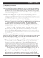
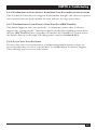
3.3 Cascading in ServSwitch Ultra Systems
In a normal cascaded ServSwitch Ultra system, the shared monitor(s), keyboard(s),
and mouse (mice) are directly attached to one or more “master” ServSwitch Ultras,
while all the CPUs are indirectly attached through “submasters” (subsidiary
ServSwitch Ultras, regular ServSwitches, ServManagers, etc.) that provide port
expansion but may or may not perform any control functions of their own. When
you cascade in this way, you can expand your system to include up to 256 ports
(sixteen 16-port submasters on a 16-port master unit).
CAUTION!
To avoid platform- and peripheral-mismatch problems, take these
precautions:
1. In any application involving CPUs belonging to different platforms,
we recommend that you use multiplatform masters and submasters.
2. If you own any of the older Apple only or Sun only ServSwitches
we used to sell, don’t try to add them to your cascade. They do not
support cascading.
3. If you attach any PC-only submasters to a multiplatform master,
make sure you attach only IBM PC compatible CPUs to those
submasters.
4. If you use any PC-only masters, we recommend that you use only
PC-only submasters. If you must use any ServManager or ServSwitch
Ultra submasters, make sure that you have those submasters set for the
keyboard and mouse type you’re using with [Ctrl] Mxx [Enter], and make
sure that those settings are saved in the submasters’ NVRAM with
[Ctrl] K.
5. All of the CPUs attached to any PC-only submaster must use the
same type of keyboard and mouse.
You can add submasters to your ServSwitch Ultra system as you need them. For
each submaster you add to the system, you add as many ports as are on that
submaster, minus the one port on each master “above” it that’s now occupied.
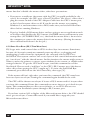
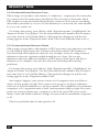
Refer to Figure 3-2 on page 30:
• Connecting one 4-port submaster Serv unit to a 4-port master ServSwitch Ultra
(top view) gives you a total of 7 ports: 4 on the submaster and another 3 (4
minus the one that the submaster is attached to) on the master.
• Connecting four 4-port submaster Serv units to a 4-port master ServSwitch
Ultra (bottom view) gives you a total of 16 ports, 4 on each submaster. (All 4
ports on the master are now occupied.)
When you use Matrix ServSwitches as submasters, the setup is a little more
complicated. Refer to Figure 3-3 on page 31: Connecting two 4-port Matrix
ServSwitch submasters to an 8-port ServSwitch Ultra master gives you a total of
14 ports on that master. (Each of the masters in Figure 3-3 can access 14 ports, but
while both masters share CPUs 1 through 8, CPUs 9 through 14 on either master
28
CHAPTER 3: Installation
can only be accessed by the monitors, keyboards, and mice on that master. Note
that when we say that CPUs 1 through 8 are “shared,” we mean that they can be
accessed by either master at different times, not by both masters simultaneously.)
Adding a third 4-port submaster unit would give you a total of 17 ports, and so on.
(To reach all of the CPUs in cascaded systems like this, you must set Maximum
computers, Width, and Units properly on the master unit; see Sections 5.2.3
through 5.2.5.)
3.3.1 CABLE REQUIREMENTS FOR EXPANSION
To connect submaster units to a ServSwitch Ultra, you’ll need one ServSwitch-toServSwitch Expansion Cable for each submaster unit. You will also need a CPU
Adapter Cable for each CPU you will be connecting to the submaster’s CPU ports.
(Remember that one MKM Adapter Cable is required to connect the master unit
to your keyboard, monitor, and mouse.) See Sections 3.2.2 through 3.2.4.
3.3.2 INSTALLING A CASCADE
Laying out your ServSwitch Ultra system prior to installation will make the installation
process go more smoothly. It will also help you to keep the port-selection numbers
you’ll use in keyboard commands in a rational sequence. Figure 3-2 on the next
page illustrates the proper layout and numbering of your submasters and CPUs.
Keep these restrictions in mind when you design your ServSwitch system:
• If you use original Serv Adapter Cables and Expansion Cables, the distance
from any ServSwitch Ultra to any attached device should not exceed 20 ft.
(6.1 m); the total length of original Serv cabling from any CPU to any monitor,
keyboard, and mouse should not exceed 40 ft. (12.2 m). Depending on your
application, these distances might be less; see Section 4.1.3.
• If you use coaxial Adapter Cables and Expansion Cables, the maximum
distance from the ServSwitch Ultra to any attached device should not exceed
20 ft. (6.1 m) with typical monitors and video resolutions, but see the Caution
notice on page 23. Depending on your application, this distance might vary;
see Section 4.1.3.
• The total number of CPU ports accessible by any ServSwitch Ultra master unit
must not exceed 256.
• Do not use older (“-R2” product code or earlier) mini (SW721 or SW722)
model regular ServSwitches as submasters in your ServSwitch Ultra system.
Their cascading logic and command language is different from that of all
other Serv type units.
29
SERVSWITCH™ ULTRA
• You must not cascade submasters to more than one “layer.” That is, you may
connect submasters to the CPU ports of one or (with Matrix ServSwitch
submasters) two master ServSwitches, but do not connect any submasters to
submasters’ CPU ports. To illustrate this restriction, let’s say you’ve installed a
four-port submaster on a four-port ServSwitch master and you have a four-port
submaster yet to install. You must install the second submaster on the master’s
CPU 2 port, not on the first submaster’s CPU 1 port. A third submaster would
have to go on the master’s CPU 3 port, a fourth on the CPU 4 port. If it
becomes necessary to attach more CPUs after “maxing out” on submasters, you
must upgrade your master or submasters.
MASTER UNIT
CPU 7
CPU 6
CPU 5
CPU 4
CPU 3
CPU 2
CPU 1
4
3
2
1
4
3
2
1
CPU3
CPU4
CPU1
CPU2
MONITOR/KEYBOARD/MOUSE
RS-232
4
3
2
1
CPU3
CPU4
CPU1
CPU2
MONITOR/KEYBOARD/MOUSE
RS-232
CPU4
CPU1
CPU2
MONITOR/KEYBOARD/MOUSE
RS-232
Max. Ports = 7
Width = 4
Units = 1
POWER
17VAC CT
SUBMASTER UNIT
CPU 16
CPU 15
CPU 14
CPU 13
CPU3
POWER
17VAC CT
MONITOR
KEYBOARD
MOUSE
POWER
17VAC CT
SUBMASTER 4
CPU 12
CPU 11
CPU 10
CPU 19
4
3
2
1
CPU3
CPU4
CPU1
CPU2
MASTER UNIT
MONITOR/KEYBOARD/MOUSE
RS-232
POWER
17VAC CT
SUBMASTER 3
CPU 8
CPU 7
CPU 6
CPU 5
4
3
2
1
CPU3
CPU4
CPU1
CPU2
MONITOR/KEYBOARD/MOUSE
RS-232
4
3
2
1
CPU3
CPU4
CPU1
CPU2
ADAPTER CABLES
CPU
SS to SS
CPU3
CPU4
CPU1
CPU2
MONITOR/KEYBOARD/MOUSE
RS-232
POWER
17VAC CT
MKM
SUBMASTER 1
Figure 3-2. Basic ServSwitch cascading.
30
MONITOR/KEYBOARD/MOUSE
RS-232
POWER
17VAC CT
POWER
17VAC CT
SUBMASTER 2
CPU 4
CPU 3
CPU 2
CPU 1
4
3
2
1
MONITOR
KEYBOARD
MOUSE
Max. Ports = 16
Width = 4
Units = 4
CHAPTER 3: Installation
• If you are attaching more than one submaster to a slimline or full-size master
ServSwitch Ultra, we strongly recommend that all of the submasters have the
same number of ports. This is because the Switch’s “Expansion width”
command/parameter—the value it uses to calculate how many ports each
attached submaster has (see Section 5.2.5)—is global rather than submasterspecific. In other words, a master ServSwitch Ultra always expects every
submaster attached to it to have the number of ports specified in Width.
For example, if you attach one 8-port submaster and one 12-port submaster
to a master ServSwitch Ultra, and then set Width to 8 (and Units to 2 and Max
Ports to 20—see Sections 5.2.3 and 5.2.4), you will be unable to scan or switch
to the upper 4 ports on the 12-port submaster—the Switch has no way of
knowing they are even there. On the other hand, if you set Width to 12 (and
Units to 2 and Max Ports to 24), your system will include 4 “phantom” ports
(nonexistent ports 9 through 12 on the 8-port submaster) that the master will
think are there and will try to scan or switch to, displaying a blank screen.
CPU 9 (B)
through
CPU 14 (B)
CPU 8
CPU 7
CPU 6
CPU 5
MASTER SERVSWITCH B
3-8
4
3
2
1
B
CPU3
CPU1
CPU4
CPU2
MONITOR/KEYBOARD/MOUSE B
MONITOR/KEYBOARD/MOUSE A
RS-232
POWER
17VAC CT
2
4
3
2
1
CPU 8
CPU 5
CPU 6
CPU 3
CPU 4
CPU 1
CPU 2
MONITOR/KEYBOARD/MOUSE
POWER
17VAC CT
RS-232
A
Max. Ports = 14
Width = 4
Units = 2
SUBMASTER MATRIX
SERVSWITCH 2
CPU 4
CPU 3
CPU 2
CPU 1
CPU 9 (A)
through
CPU 14 (A)
CPU 7
1
MONITOR
KEYBOARD
MOUSE
SUBMASTER MATRIX
SERVSWITCH 1
CPU3
CPU4
MONITOR/KEYBOARD/MOUSE B
CPU1
CPU2
MONITOR/KEYBOARD/MOUSE A
B
RS-232
POWER
17VAC CT
A
MASTER SERVSWITCH A
3-8
ADAPTER CABLES
CPU
SS to SS
MKM
2
CPU 7
CPU 8
CPU 5
CPU 6
1
CPU 3
CPU 4
CPU 1
CPU 2
Max. Ports = 14
Width = 4
Units = 2
MONITOR/KEYBOARD/MOUSE
POWER
17VAC CT
RS-232
MONITOR
KEYBOARD
MOUSE
Figure 3-3. Cascading with Matrix ServSwitch submasters.
31
SERVSWITCH™ ULTRA
When you’re ready to begin hooking up the actual units, follow these steps:
1. If this hasn’t already been done, connect the monitor(s), keyboard(s), and
mouse (mice) to the MONITOR/KEYBOARD/MOUSE port(s) of your
master device(s) as outlined in Section 3.2.2.
2. Use ServSwitch-to-ServSwitch Expansion Cables (see Section 3.2.4) to connect
all your submaster units to the master unit’s CPU ports, beginning with the
port labeled CPU 1 and continuing with CPU 2, CPU 3, etc. (Avoid installing
submasters with different numbers of CPU ports on the same master; if
possible, every Serv unit in your cascade should have the same number of
ports.)
3. Using CPU Adapter Cables, attach your computers to available CPU ports: the
first computer into the port identified as CPU 1, CPU #2 into its port, etc. (see
Section 3.2.3). The computers should all be OFF; do not turn them ON yet.
4. Attach the power supplies to the master(s) and to the submasters. Plug in the
power supplies, but do not turn the master(s) or submasters ON.
5. Turn ON all of the submaster units, then the master unit(s). They should
boot normally, but if the firmware in any of the units has become corrupted—
probably as the result of a firmware upgrade going wrong—the affected unit
will display this message on all attached monitors that have it selected:
Kernel is bad, load new kernel through serial port
If you see this, you will need to download correct firmware to the affected unit
as described in Section 4.4.3, starting at the point at which the unit is ready to
receive the file at 9600 baud (9600 bps). (In this case, you must download the
file at 9600 bps.)
6. If all of your computers are Sun type, see Section 3.2.5 for the power-up
procedure for your CPUs. Otherwise, turn ON the computer identified as
CPU 1. Wait until the boot process is complete, then turn ON CPU 2, wait
until it boots, turn ON CPU 3, etc., until all of your computers are powered
up.
7. Set each master’s Maximum computers, Expansion units, and Expansion
width values so that the master can scan correctly and properly control the
interplay of the submaster units. You can do this with the on-screen display—see
Sections 5.2.3 through 5.2.5.
32
CHAPTER 3: Installation
8. You might need to set some or all of each master’s remaining configuration
parameters, especially the keyboard mode for some of your ports (see
Sections 5.2.1, 5.2.2, and 5.2.6 through 5.2.10).
9. Save the configuration changes you just made to the master unit’s nonvolatile
memory as described in Section 5.1.3.
Your cascaded ServSwitch Ultra system should now be ready for operation.
33
SERVSWITCH™ ULTRA
4. Operation: Hardware and
Keyboard Commands
The first part of this chapter, Section 4.1, gives you some guidelines that you
should follow to make sure your ServSwitch Ultra works properly with your
equipment.
Section 4.2 summarizes the ServSwitch Ultra’s keyboard commands, and Section
4.3 describes these commands in detail.
Section 4.4 outlines how you can select ports or upgrade firmware from an
optional computer or terminal connected to the ServSwitch Ultra’s RS-232 port.
NOTES
If, as you prepare to operate the ServSwitch Ultra, you see a prompt on
your screen asking you to “Enter password,” you must type in the
unit’s access password before the ServSwitch will allow you to enter
commands. See Section 5.5.2.
To start any ServSwitch Ultra keyboard command, you must press and
release the left Control Key ([Ctrl]). Pressing and releasing [Ctrl] cues
the Switch to expect command characters from the keyboard. You then
have two seconds in which to start entering a valid command. If no
command is begun within two seconds or if an invalid command is
entered, the ServSwitch aborts the command.
When entering commands that contain numbers or math symbols, use
only the numeral keys located at the top of your alphanumeric keyboard.
Numbers and symbols entered from the numeric keypad to the right will
not be recognized as valid.
4.1 Guidelines for Using the ServSwitch Ultra with Your Equipment
4.1.1 CPUS
For your IBM PC type CPUs, use only IBM PC/AT or PS/2 or 100% compatible
machines. The ServSwitch Ultra does not support IBM PC/XT™ or compatible
machines. It does not support machines that output CGA or EGA video. (Because
the basic hardware design for Sun and Apple CPUs has remained backwardcompatible, the ServSwitch Ultra supports all Apple and Sun machines.) Any SGI
machines you attach must output the current type of SGI video on 13W3
connectors or standard VGA video on HD15 connectors.
34
CHAPTER 3: Installation
4.1.2 MOUSE AND KEYBOARD
When you power up your ServSwitch Ultra system, make sure that your CPUs,
mouse (mice), and keyboard(s) are properly cabled to the Switch (or to the
appropriate master or submaster unit). When you boot up your CPUs, the
master(s) and/or submasters to which they are connected should already be ON.
(You should be able to freely disconnect and reconnect a mouse or keyboard from
a ServSwitch Ultra while the Switch is ON, but if you experience problems when
you do this, issue the Reset command [CTRL] R—see Section 4.3.7.)
Though the ServSwitch Ultra can convert any supported keyboard or mouse
protocol to any other, this is not enough to overcome all of the vast differences
between input devices. If all of your CPUs are of the same type, we recommend
that you use the corresponding type of keyboard and mouse. If your CPUs are of
different types, certain limitations tend to favor the use of certain keyboard and
mouse types:
Standard PC keyboards have 101 or 102 keys. PC keyboards designed specifically
for Windows 95/98/2000 have 104 or 105 keys. At this time there is no way for a
101-/102-key keyboard to emulate the functions of the Windows Start ( ) and
Windows Application ( ) keys on a 104-/105-key keyboard. Standard Apple
keyboards have 105 keys. And standard (Type 5 or higher) Sun keyboards have
118 keys as well as keyclick and beep features. We have mapped several of the
Apple and Sun keys to the PC keyboards (see Table 4-1 on page page 37), but
many of the Sun keys simply cannot be mapped to IBM or Apple keyboards.
Similarly, standard Apple mice have one button; standard PC mice have two or
three buttons; and standard Sun mice have three buttons. At this time there is no
way for a one- or two-button mouse attached to the ServSwitch Ultra to emulate a
mouse with more buttons.
For these reasons, we recommend that you use Sun Type 5 or higher keyboards
and Sun mice for mixed-platform applications that include Sun CPUs. For
applications that include IBM and Apple CPUs but no Sun CPUs, we recommend
that you use IBM keyboards and mice, because the IBM keyboard can emulate all
of the Apple keyboard functions, but the one-button Apple mouse simply can’t
effectively operate IBM applications that lean heavily on the center or right mouse
button. In particular, use Windows type IBM keyboards if any of your CPUs/
applications require the Windows keys, and use three-button IBM mice if any of
your CPUs/applications require the center mouse button.
Other concerns:
• The ServSwitch Ultra supports a variety of IBM PC type mice; for more details,
see Section 5.2.2.
35
SERVSWITCH™ ULTRA
• Because the ServSwitch Ultra currently only supports “stream mode”
(continuous) mouse data, but older IBM ThinkPad models have to handle
mouse data in “prompt mode” (burst-on-request), don’t try to attach any older
ThinkPad computers to the Switch, either directly or through docking stations.
Some newer models should work with the Switch, but there’s no good way to
tell other than by trial and error—exercise caution!
• If you are using a PC mouse as the common mouse, make sure that the IBM
PC CPUs use only the generic Microsoft mouse driver MOUSE.COM, version 4.0
at least and preferably version 9.01 or higher. If you’re running Windows® 3.x,
this driver must be loaded in Windows as well as in DOS. Do not, on any of
your switched IBM PC CPUs, run any programs or TSRs, or enter any DOS
commands, that change the settings of the mouse port after the driver has
been loaded.
• When you first switch between CPUs, especially CPUs of different platforms,
you might notice wide variations in mouse sensitivity (how far or fast the
mouse moves) from CPU to CPU. This is normal. All three of the major
platforms supported by the ServSwitch Ultra (IBM, Apple, and Sun) have ways
to adjust the sensitivity of the mouse. (This is usually handled through some
kind of software “control panel,” but the specifics vary depending on the
operating system and—in IBM applications—on the mouse driver.) To
optimize mouse movement, adjust the sensitivity on each CPU according to
your individual preference.
• Although the ServSwitch Ultra resists minor transient surges that can be
caused by rapidly cycling power, certain keyboards are sensitive to such
transients. Because your shared keyboard’s power is provided by the Switch,
wait at least three seconds after powering down the Switch before powering it
up again, or the keyboard might not reset correctly.
• The ServSwitch Ultra is designed to support IBM PC compatible 101-, 102-,
104-, or 105-key keyboards and IBM PC keyboard-scan modes 1, 2, and 3; it’s
also designed to work with PC-type CPUs/keyboards that use 5-pin DIN or
6-pin mini-DIN keyboard connectors. The Switch will try to pass through
keyboard codes that it doesn’t recognize without altering them, which allows it
to support the DEC™ LK461 keyboard (see Appendix D for the key mappings),
Japanese 106- and 109-key keyboards, and certain other keyboards that use
special or proprietary keys. However, we cannot guarantee that the ServSwitch
Ultra will be able to fully support—or even work at all with—any PC-type
keyboard that uses nonstandard keys, connectors, or keyboard-scan modes.
• If you are using a Sun keyboard, it must be a Type 5 or Type 5c. The
ServSwitch Ultra will autodetect the keyboard’s language.
36
CHAPTER 4: Operation: Hardware and Keyboard Commands
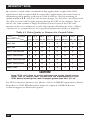
Table 4-1. Keyboard Mapping by the ServSwitch Ultra
Generally, the ServSwitch Ultra interprets keys by their positions on the keyboard, so any keys
that occupy more or less the same positions and perform more or less the same functions
across platforms will map one-to-one. However, certain keys available on certain keyboards do
not correspond well or are not available on other types of keyboards, so the Switch maps the
more important of these as shown below (see also Section 4.3.10).
On the Sun
keyboard, the
___ key:
Control
Alt
Left Command (◆)
Right Command (◆)
Compose
Alt Graph
Power ( |)
Emulates the
PC 101/102-key
keyboard’s ___ key:
Left Ctrl
Left Alt
N/A
N/A
Right Ctrl
Right Alt or Alt Graph
N/A
Emulates the
PC 104/105-key
keyboard’s ___ key:
Left Ctrl
Left Alt
Left Win Start (
)
Right Win Start (
)
Right Ctrl
Right Alt or Alt Graph
Windows App ( )
Emulates the
Apple keyboard’s
___ key:
Left Control
Left Option (alt)
Left Command ()
Right Command ()
Right Control
Right Option (alt)
Power (
)
On the IBM PC 101/ (Maps to same
102-key keyboard,
key on PC 104/
the ___ key:
105-key keyboard.)
Left Ctrl
Left Alt
Right Alt or Alt Graph
Right Ctrl
Emulates the
Apple keyboard’s
___ key:
Left Control
Left Command ()
Right Option (alt)
Power (
)
(Not recommended)
Emulates the Sun
keyboard’s ___ key:
Left Control
Left Command (◆)
Alt Graph
Power ( |)
On the IBM PC 104/ (Natively supports
105-key keyboard,
PC 101/102-key
the ___ key:
keyboard functions.)
Left Ctrl
Left Win Start (
)
Left Alt
Right Alt or Alt Graph
Right Win Start (
)
Win App ( )
Right Ctrl
Emulates the
Apple keyboard’s
___ key:
Left Control
Left Command ()
Left Option (alt)
Right Option (alt)
Right Command ()
Power (
)
Right Control
(Not recommended)
Emulates the Sun
keyboard’s ___ key:
Left Control
Left Command (◆)
Alt
Alt Graph
Right Command (◆)
Power ( |)
Compose
On the Apple
keyboard*, the
___ key:
Left Control
Left Option (alt)
Left Command ()
Right Command ()
Right Option (alt)
Right Control
Power (
)
Emulates the
PC 104/105-key
keyboard’s ___ key:
Left Ctrl
Left Alt
Left Win Start (
)
Right Win Start (
)
Right Alt or Alt Graph
Right Ctrl
N/A
(Not recommended)
Emulates the Sun
keyboard’s ___ key:
Control
Alt
Left Command (◆)
Right Command (◆)
Alt Graph
Compose
Power ( |)
Emulates the
PC 101/102-key
keyboard’s ___ key:
Left Ctrl
Left Alt
N/A
N/A
Right Alt or Alt Graph
Right Ctrl
N/A
*You should not use the Apple keyboard to emulate an IBM or Sun keyboard unless the operating systems and
applications running on your system’s IBM or Sun CPUs do not require the center or right mouse button and do not
require any of the “missing” Sun keys other than [Stop] (see Section 4.3.10).
37
SERVSWITCH™ ULTRA
4.1.3 MONITOR
If all of your CPUs are of the same type, we recommend that you use the
corresponding type of monitor. If your CPUs are of different types, the monitor
must be a multisync model, able to sync to every CPU’s video-output frequencies,
and compatible with all of the CPUs’ video cards.
While PC-type CPUs and VGA monitors normally use two separate leads to
send/receive sync signals, one lead for horizontal sync and one for vertical sync,
Mac and Sun CPUs/monitors normally send/receive a composite sync signal on a
single lead. This means that if you attach both IBM and Mac or Sun CPUs to your
system, either your monitor must be capable of accepting both H/V and
composite-sync input, or you will have to use a sync converter and special cables to
convert H/V to composite sync or vice versa (call Black Box Technical Support for
a special quote).
For maximum compatibility, we recommend a 17" or larger, high-quality
multisync monitor capable of (a) displaying a maximum resolution of not less than
1280 x 1024 at a maximum refresh rate of not less than 75 Hz, and (b) accepting
both relevant types of sync input (H/V and composite). Such monitors are
available from NEC, Sony®, CTX®, and other manufacturers. (However, since these
monitors usually have an HD15 video-input connector, you will need a special User
Cable to use them with Mac or Sun keyboards and mice; the Sun cable is product
code EHN059 [original] or EHN225 [coax], and the Mac cable is EHN532
[original] or EHN540 [coax].) The higher the resolution you use, the less distance
you can run; see Tables 4-2 and 4-3 on the following pages.
Other concerns specific to IBM PC systems:
• The ServSwitch Ultra is designed to support standard VGA video, including VGA
monochrome (“page white”). It does not support PCs that use CGA, EGA, or
proprietary versions of VGA that depart from the original specifications.
Consult your PC’s manual, and if that doesn’t tell you whether or not the PC
uses standard VGA, consult with the PC’s or the video card’s manufacturer.
• The ServSwitch Ultra is also designed to support SVGA, although it doesn’t
handle higher resolutions or longer distances very well without coaxial cabling
(see the next two pages). With coaxial cables, it will also support XGA,
RS/6000, and SGI video (RS/6000 and SGI require cables with 13W3
connectors—see Appendix B).
If you have Mac CPUs attached, you’ll need a Mac Adapter for ServSwitch
(product code KV99MA) for each CPU that outputs video in a format other than
VGA (640 x 480)—see the Note on page 23.
38
CHAPTER 4: Operation: Hardware and Keyboard Commands
The ServSwitch Ultra will support SVGA (Super VGA) video, but with original
Serv cables the video quality will decrease markedly at higher resolutions and
distances. Table 4-2, below, illustrates this. The distances in the table are total cable
lengths measured from the CPU to the monitor. The table assumes that one
ServSwitch Ultra is between the CPU and monitor; in a cascaded application with a
ServSwitch Ultra and one or more submasters between the CPU and monitor,
video quality will always be lower.
This table also applies to Mac video in ServSwitch Ultra systems in which the Mac
versions of the original Serv cables (product codes EHN210 and EHN215) have
been installed.
Table 4-2. Video Quality vs. Distance for Original Serv Cables
Distance 5' (1.5 m) 10' (3 m) 15' (4.6 m) 20' (6.1 m) 25' (7.6 m)
Resolution
640 x 480
3
3
3
3
3
800 x 600
3
3
3
2
2
1024 x 768 interlaced
3
3
2
2
2
1024 x 768 noninterlaced
3
2
2
2
2
1280 x 1024 interlaced
2
1
1
1
1
1280 x 1024 noninterlaced
2
1
1
1
1
1600 x 1280
2
1
1
1
1
Quality 3 = Near perfect; screen defects are not conspicuous
Quality 2 = Good to very good; images are clear; there are small reflections around
text lettering depending on the color; screen defects are sometimes
conspicuous
Quality 1 = Fair to poor as distance increases; images run from slightly fuzzy to
badly smeared; text runs from fuzzy but readable to completely
washed out
39
SERVSWITCH™ ULTRA
By contrast, coaxial cables (standard for Sun applications, required for XGA
applications, and recommended for most other applications) do much better at
maintaining video quality, as shown in Table 4-3 below. (For the meaning of
quality numbers 3, 2, and 1, see the bottom of page 39.) As before, the distances in
the table are total cable lengths measured from the CPU to the monitor. Also as
before, the table assumes a single ServSwitch Ultra is between the CPU and
monitor; if there is a submaster as well, video quality will always be lower. (Where
“interlaced” or “noninterlaced” isn’t specified, noninterlaced video is implied.)
Table 4-3. Video Quality vs. Distance for Coaxial Cables
Distance
Resolution
10 ft. 20 ft. 30 ft.
50 ft.
75 ft.
100 ft.
150 ft. 200 ft.
(3 m) (6.1 m) (9.1 m) (15.2 m) (22.9 m) (30.5 m) (45.7 m) (61 m)
640 x 480
3
3
3
3
3
3
2
2
800 x 600
3
3
3
3
3
3
2
2
1024 x 768 interlaced
3
3
3
3
3
3
2
2
1024 x 768 noninterl.
3
3
3
3
2
2
2
1
1280 x 1024 interlaced
3
2
2
2
2
1
1
1
1280 x 1024 noninterl.
3
2
2
1
1
1
1
1
1600 x 1280
3
2
2
1
1
1
1
1
CAUTION!
Some CPUs can’t drive or receive keyboard and mouse signals across
longer runs of coaxial cable. Consult with the manufacturers of your
CPUs before installing this cable in lengths greater than 20 ft. (6.1 m).
For CPU-to-monitor distances over 200 feet (61 m) in IBM PC applications, Station
Extenders or CAT5 KVM Extenders might be required. Call Black Box for
technical support to discuss this option.
40
CHAPTER 4: Operation: Hardware and Keyboard Commands
4.2 Keyboard-Command Summary
Table 4-4 below and on the next two pages summarizes the commands that can be
sent to the ServSwitch Ultra. To enter any command at the shared keyboard, first
press and release the left Control key, represented by “[Ctrl].” (This cues the
Switch to look for commands from that keyboard.) Then enter the command
followed by any arguments you wish to specify (the port number, for example).
Letter commands are not case-sensitive; they are all shown in uppercase for
clarity only.
When you enter numeric commands or arguments, use only the numbered keys
at the top of your alphanumeric keyboard. Numbers entered from the numeric
keypad to the right will not be recognized as valid commands.
All of these commands have a two-second timeout between characters. This
means that if you begin entering a command, but you stop for more than two
seconds at any time before you type the final character, the command is aborted
and the ServSwitch Ultra returns to normal operation. This keeps the Switch from
getting stuck waiting for you to finish the command.
The [Ctrl] character is always passed through to the CPU. The command
characters and operands, however, are absorbed by the ServSwitch Ultra and are
not sent to the CPU.
Many of these commands have factory-default values (see Appendix A) that can
be reloaded if your Switch becomes badly misconfigured; see Section 6.1.
Table 4-4. The ServSwitch Ultra’s Keyboard Commands
Command
Keystroke Sequence
Description
Select Port
[Ctrl] xxx
(xxx = a 1- to 3-digit port
number)
Connects your shared monitor, keyboard, and
mouse (user station) to the specified port.
Switch to the
Next Port
[Ctrl] +
Switches to the next port in sequence. (You can
also access the next port by pressing the “” or
“+” button on the ServSwitch Ultra’s front panel.)
Switch to the
Previous Port
[Ctrl] –
Switches to the previous port in sequence. (You
can also access the previous port by pressing the
“” or “–” button on the Switch’s front panel.)
Scan ON
[Ctrl] S
Turns Scan mode ON, causing the ServSwitch
Ultra to start scanning sequentially from the
current port through the remaining ports and then
begin again at Port 1.
41
SERVSWITCH™ ULTRA
Table 4-4. The ServSwitch Ultra’s Keyboard Commands (continued)
Command
Keystroke Sequence
Description
Scan OFF
[Ctrl] X
Turns Scan mode OFF (the port being scanned at
the time the command is entered is given access
to the shared monitor, keyboard, and mouse).
Note: Scan can also be stopped by entering a
Select Port command.
Keep Settings
[Ctrl] K
Enter this command after you enter either of the
following two commands (it saves new settings to
nonvolatile memory):
Set Screen
Saver’s Delay
Time
[Ctrl] Vxxx
Sets the time of inactivity, in seconds, after which
[Enter] (xxx = delay in the ServSwitch Ultra will blank the shared
seconds)
monitor’s screen. (The monitor is reactivated
when the mouse is moved or any key on the
shared keyboard is pressed.)
[Ctrl] B
Transpose
Command and
Alt Keys
Causes the Switch to logically “swap” the
mappings of the command or start keys and the
adjacent alt/alt graph keys (see Section 4.3.6).
[Ctrl] R
Resets and enables the keyboard and mouse.
Issue this command to correct your keyboard or
mouse if one of them malfunctions or gets stuck.
Send Null Byte [Ctrl] N
Causes the Switch to send a null byte to the
CPU’s PS/2 mouse port. Issue this command to
correct the current CPU if it gets “out of sync” with
the PS/2 mouse (see Section 4.3.8).
Reset
Identify ROM
[Ctrl] I
Causes the ServSwitch Ultra to report the version
of ROM it is using. Issue this command if you are
asked to do so by a technical-support person.
Send [Stop]
[Ctrl] [Pause]
Causes the ServSwitch Ultra to send the scan
code for the [Stop] character (the only widely
used non-mapped key on the Sun keyboard) to
the currently selected CPU.
Display Label
[Ctrl] D
Causes the ServSwitch Ultra to display the onscreen computer label of the currently selected
CPU for the currently configured fadeout time (or
for three seconds if fadeout is disabled).
Activate OnScreen Menus
[Ctrl] [F12]
Causes the ServSwitch Ultra to display its onscreen overlay menus.
42
CHAPTER 4: Operation: Hardware and Keyboard Commands
Command
Keystroke Sequence
Activate Select [Ctrl] [ESC]
Window
Log Out
[Ctrl] L
Description
Causes the ServSwitch Ultra to display its
“computer select window” (see Section 5.5).
Logs out the current user if an access password
has been set; video is blanked and keyboard and
mouse input is locked until a user enters the
access password. If no access password has
been set, turns on the screen saver.
4.3 The Commands in Detail
4.3.1 SELECTING A PORT FROM THE SHARED KEYBOARD
To select a port from your keyboard, press and release your keyboard’s left Control
key ([Ctrl]), then type in the port number:
If “Maximum Ports” is set to 1 to 9: The ServSwitch Ultra will immediately switch
to the desired port when you press the one-digit number’s numeral key.
If “Maximum Ports” is set to 10 to 99: The ServSwitch Ultra will immediately
switch to the desired port when you press the two-digit number’s second numeral
key. For single-digit ports, you can enter the number by including a leading zero
(“01” for port 1) or by pressing [Enter] after you press the single numeral key. If
you press the key of only one digit, and do not follow it with [Enter], the Switch
will wait two seconds for you to press [Enter] or another numeral key; then, if no
key is pressed, it will switch immediately to the single-digit port.
If “Maximum Ports” is set to 100 to 256: The ServSwitch Ultra will immediately
switch to the desired port when you press the three-digit number’s third numeral
key. For single- and double-digit ports, you can enter the number by including one
or two leading zeros (“001” for port 1 or “027” for port 27) or by pressing [Enter]
after you press the single or second numeral key. As noted above, the Switch will
wait two seconds for you to enter another digit, then will switch to the partially
entered port number.
4.3.2 SWITCHING TO THE NEXT OR PREVIOUS PORT
From the keyboard you can go forward or backward through the ServSwitch Ultra’s
ports by selecting either the next or the previous port respectively. To switch to the
next port, press and release the left Control key ([Ctrl]), then press the plus key
(the key at the top of the keyboard marked with [=] and [+]). To switch to the
previous port, press and release [Ctrl], then press the minus key (the key at the top
43
SERVSWITCH™ ULTRA
of the keyboard marked with [–] and [_]). The command is not case-sensitive. Do
not use the [+] and [–] keys on the keyboard’s numeric pad; the Switch doesn’t
recognize these.
You can also select the next or previous port manually from the ServSwitch
Ultra’s front panel by pushing the button labeled “” or “” respectively (“+” or
“–” on the 2-port units). Each time you press the button, the next or previous port
in sequence is selected.
4.3.3 SCAN MODE
To start scanning (switching from CPU to CPU in a continuous rotation) from the
keyboard, press and release the left Control key ([Ctrl]), then press [S]. The
ServSwitch Ultra will begin scanning sequentially from its currently selected port
through the higher-numbered ports, then begin again at CPU Port 1. As it scans, it
delays 1 to 15 seconds at each port. (This “Scan-Delay Time” is user-selectable; see
Section 5.2.6.) To stop scanning, press and release [Ctrl], then press [X]; you can
also stop a scan by entering a Select Port command. ServSwitch Ultra letter
commands are not case-sensitive: You can enter upper- or lower-case letters.
To disable scanning, set the scan-delay time to zero; see Section 5.2.6.
4.3.4 KEEP SETTINGS
The Keep Settings command saves the current state of the ServSwitch Ultra’s two
keyboard-selectable settings (“Set Screen-Saver Interval” and “Transpose Command
and Alt Keys,” described in the next two sections) to nonvolatile memory
(NVRAM), where they become the new default (loaded at power-up) settings. To
enter the command, press and release the left Control key, then type [K].
4.3.5 SET SCREEN-SAVER INTERVAL
This feature reduces the wear on your shared screen and provides security for your
system by blanking the screen when there has been no keyboard activity for a
specified length of time. To set the screen-saver interval, press and release the left
Control key, type [V] followed by the interval time in seconds (1 to 999, or 0 to
disable the screen saver), and press [Enter]. Issue the Keep Settings command
after you enter this command.
To reactivate the screen when it’s been blanked, press any key on the keyboard
or move the mouse. The default setting of this option is 0 (screen saver disabled).
NOTE
When the ServSwitch Ultra is in the Screen-Saver state, all of its
SELECT LEDs (the left-hand, red port LEDs) will be OFF.
44
CHAPTER 4: Operation: Hardware and Keyboard Commands
4.3.6 TRANSPOSE COMMAND AND ALT KEYS
This command is designed to make life easier for people used to the Sun or Mac
keyboard who now need to use a Windows 95/Windows 98 style (104/105-key) PC
type shared keyboard, or vice versa. In the ServSwitch Ultra’s default setting, the
Start and Alt (“Alt” or “Alt/Alt Graph”) keys on the Win95/Win98 keyboard map
to the Command and Alt (“Alt”, “Option [Alt]”, or “Alt Graph”) keys respectively
on the Sun and Mac keyboards, even though the Win95/Win98 Start and Alt keys
are reversed (“backwards”) with respect to the Sun and Mac Command and Alt
keys.
Many people who have grown used to typing or triggering an application’s
functions with “the other” type of keyboard find it difficult to adjust to this reversal.
If you don’t want to adjust, you don’t have to; use this command to have the Switch
transpose (swap) the scan codes of these keys when it does its keyboard mapping,
so that when you press the Alt key, the Switch sends the corresponding Command
or Start scan code to the selected CPU instead, and when you press the Command
or Start key, the Switch sends the Alt scan code instead.
To issue the Transpose Command and Alt Keys command, press and release the
left Control key, then type [B]. (Reissue this command to switch back to the
standard mapping.) Enter the Keep Settings command after you enter this
command.
4.3.7 RESET
This command, along with the commands described in the next two sections, can
come in handy when certain problems arise. It will reboot your keyboard and
mouse without your having to power down the station or the system, and will also
re-enable PS/2 mouse communication if the selected CPU has previously disabled
it. (With current PCs and operating systems, this command shouldn’t be necessary,
but older CPUs running DOS or Windows might need it from time to time.) Issue
this command if (a) your keyboard gets stuck or begins behaving oddly, (b) you
need to send mouse data to the CPU, but it hasn’t enabled the mouse (this can
happen if you boot up the CPU while the ServSwitch Ultra is off or disconnected),
or (c) while using a PS/2 type mouse, you unplug it, plug it back in, then have
problems. To issue the Reset command, press and release the left [Ctrl] key, then
type [R].
If you’re using a PS/2 type mouse with a DOS or Windows 3.x CPU, don’t issue
this command if the CPU doesn’t have a mouse driver loaded—many such CPUs
will crash if you send them unexpected mouse data. (CPUs running UNIX or
Windows 95, 98, or NT don’t have this problem.) If your shared CPU is like this,
and you have chronic problems when you try to run applications that don’t use the
45
SERVSWITCH™ ULTRA
mouse but don’t disable the mouse either, take these precautions:
• If you never actually use the mouse with the CPU (as would probably be the
case if, for example, the CPU were a Novell® NetWare® file server), either don’t
plug the mouse strand of the CPU Adapter Cable into the CPU’s mouse port,
or don’t load a mouse driver at all. If you do use the mouse, are running
Windows 3.x, and sometimes exit to DOS, make sure you load a DOS mouse
driver before running Windows.
• If you’ve loaded a DOS mouse driver and are going to use an application such
as NetWare that disables the PS/2 mouse, first REM out any statements in your
startup files (AUTOEXEC.BAT, etc.) that load the mouse driver, then reboot
the computer to remove the mouse driver from memory. (Having the mouse
driver unload itself doesn’t do the job.)
4.3.8 SEND NULL BYTE (PS/2 TYPE MICE ONLY)
PS/2 type mice send control data to CPUs in three-byte increments. Sometimes,
because of electronic transients, unusual power-up effects, or plugging and
unplugging of cables from live equipment, the currently selected CPU in a
ServSwitch Ultra system can lose one or two bytes of this control information and
get “out of sync” with the shared mouse. In this situation, the mouse might seem to
refuse to move the pointer or cursor, open windows for no reason, or exhibit other
strange behavior. To get the CPU back in sync, send this command to tell the
ServSwitch Ultra to send a “null byte” to the CPU’s PS/2 mouse port (this has no
other effect than getting the CPU “caught up”). To issue the Send Null Byte
command, press and release the left Control key, then type [N].
If the mouse still isn’t right after you issue this command, the CPU must have
been two bytes out of sync. Issuing the command again should do the trick.
The CPU will be thrown out of sync if it uses a PS/2 mouse and it’s in sync when
you issue this command. Issue this command two more times to get it back in sync
again. This command has no effect on serial mice, or on CPUs that are not
attached to your ServSwitch system through a PS/2 mouse port.
If you have version 9.01 or higher of the Microsoft mouse driver, the CPU should
never get out of sync. Contact Microsoft if you would like to upgrade your
Microsoft mouse driver.
46
CHAPTER 4: Operation: Hardware and Keyboard Commands
4.3.9 IDENTIFY ROM
Unfortunately, as with all complex equipment, problems might arise with your
ServSwitch Ultra that require the assistance of technical-support personnel. One of
the things technicians might want to know when they attempt to diagnose and
correct your problem is the revision level of your Switch’s ROM. This command
causes the ServSwitch Ultra to send the four-character “UPxx” ROM level to the
currently selected CPU as ASCII keyboard data; these characters will be echoed
back to the shared monitor if you are at some type of prompt. (You must be at
some kind of prompt or screen capable of displaying typed-in keyboard characters,
or you will not see the Switch’s response.) To issue the Identify ROM command,
press and release the left Control key, then type [I].
4.3.10 SEND [STOP]
The Sun keyboard has too many keys for them all to be mapped one-to-one to keys
on a PC or Mac keyboard, so there are a few Sun keys that PC and Mac keyboards
can’t directly reproduce. (See Section 4.1.2 and Table 4-1 on page 37.) If you
absolutely have to use a PC or Mac shared keyboard, you can use this command to
cause the ServSwitch Ultra to send the currently selected CPU the scan code for
the Sun [Stop] key. (This key, on the left-hand end of the Sun keyboard, is the
only one of the non-mapped keys that is widely used at the time of this writing; it
can be used, for example, in the [Stop][A] key sequence to cause some Sun CPUs
to go to a boot prompt.)
To issue the Send [Stop] command, press and release the left Control key, then
press the [Pause] key (often labeled [Pause (Break)] on PC keyboards or
[F15 (Pause)] on Mac keyboards). This command is valid even if issued from a Sun
keyboard. Do not send [Stop] to a PC or Mac compatible CPU; this could have
unpredictable results.
4.3.11 DISPLAY LABEL
One of the ServSwitch Ultra’s graphic-overlay functions is to display the on-screen
“label” window that contains the number and assigned name of the currently selected
CPU (see Section 5.4.3). If this label is not on screen, you can use this command to
cause the Switch to display the label for the length of time you have configured for
the label’s “fadeout interval” (see Section 5.4.3.D), or, if fadeout is disabled, for
five seconds. (If fadeout is set to 255, the label will be displayed at all times.)
Conversely, if the label is being displayed and you want it to go away, issuing the
Display Label command while the label is on screen will cause it to disappear.
To issue the Display Label command, press and release the left Control key, then
type [D].
47
SERVSWITCH™ ULTRA
4.3.12 ACTIVATE ON-SCREEN MENUS
You can use this command to cause the ServSwitch Ultra to display its on-screen
overlay menus, beginning with the main menu (see Section 5.1.1). To issue the
Activate On-Screen Menus command, press and release the left Control key, then
press and release the [F12] key.
4.3.13 ACTIVATE SELECT WINDOW
You can use this command to cause the ServSwitch Ultra to display its “computer
select window” (see Section 5.5). To issue the Activate Select Window command,
press and release the left Control key, then press and release the [ESC] (escape) key.
4.3.14 LOG OUT
If an access password has been set for your ServSwitch Ultra system (see
Section 5.5.2), you can use this command to log out (to relinquish access rights)
when you’re finished with a session at a user station. This will cause the ServSwitch
Ultra to display an “Enter password” prompt and stop accepting any keyboard and
mouse input except the access password; a few seconds later, it will blank the
screen with the currently selected screen saver. While no one is logged in—that is,
until someone correctly enters the access password—typing at the keyboard will
cause the “Enter password” prompt to briefly become visible, but otherwise, no
computer video will be displayed and no keyboard and mouse access will be
allowed.
If no access password has been set for your system, you can use this command to
cause the ServSwitch Ultra to display its currently selected screen saver (see
Section 5.4.1.C). Normal video will be restored as soon as someone types at the
keyboard or moves the mouse.
To log out, press and release the left Control key, then type [L].
48
CHAPTER 4: Operation: Hardware and Keyboard Commands
4.4 Using the RS-232 Port
4.4.1 CONNECTING EQUIPMENT TO THE PORT
For your convenience, a computer or terminal with a TIA RS-232 serial port can be
connected to the RS-232 serial port (RJ-12 connector) on the ServSwitch Ultra’s
rear panel (see Appendix C for a pinout of this connector). This allows you to send
switching commands from a non-local keyboard rather than from the shared
keyboard, and is also necessary in order to download future firmware upgrades
into the Switch. You’ll need a straight-through-pinned, flat-satin or twisted-pair
serial cable with RJ-12 (“6-pin RJ-11”) connectors plus the appropriate adapter: for
IBM and Sun type PCs and most terminals, either DB25 female to RJ-11 female
(our product code FA044) or DB9 female to RJ-11 female (our product code
FA043), depending on your computer/terminal.
NOTE
Because the serial ports of Apple Macintosh computers use a
proprietary interface with EIA/TIA RS-422/423 signal levels rather than
RS-232, a special adapter or interface converter is required to connect
them to the ServSwitch Ultra’s RS-232 port (call Black Box for technical
support if you really want to do this). We strongly recommend that you
use some other type of computer to make this connection.
To connect the adapter and cable, take these steps:
1. Connect an adapter of the appropriate type to one of the computer’s (or
terminal’s) serial ports.
2. Plug one end of the cable into the RJ-12 female connector on the adapter,
and the other end into the RS-232 serial port on the ServSwitch Ultra’s rear
panel.
CAUTION!
Serial cabling in excess of 50 feet (15.2 m) should be routed with
caution. The maximum cable length depends upon the construction of
the cable and its routing. For extended runs, shielded cable should be
used. Avoid routing near fluorescent lights, air-conditioning
compressors, or machines that may create electrical noise. If you
experience a lot of data errors, use shorter cables. The ServSwitch
Ultra’s lowest data rate is 9600 bps; it cannot be lowered any further to
alleviate this problem.
49
SERVSWITCH™ ULTRA
4.4.2 SWITCHING PORTS REMOTELY (OPTIONAL)
To switch ports on a ServSwitch Ultra from a remote computer or terminal
attached to the Switch’s RS-232 port, take these steps:
1. Set your computer for serial communication at 9600 bps, no parity, 8 data
bits, and 1 stop bit.
2. To switch the ServSwitch Ultra to a different port, use a terminal-emulation
program to type or send the desired port number followed by [Enter]
(a return).
NOTE
If you type or send a “?” (question mark) rather than a port number, the
single or master Serv unit will send the number of the currently selected
port minus one back to the remote computer or terminal—as an 8-bit
binary byte. For example, if you currently have port 1 selected, the
Switch will respond to “?” with the byte “00000000” (binary zero); if you
have port 3 selected, the Switch will respond with “00000010” (binary
two); and so on. You must be at some kind of prompt or screen capable
of displaying serially received text characters in order to see the
Switch’s response.
Of course, because most terminal emulators and similar programs
will interpret these values as ASCII codes, they will try to display the
corresponding ASCII characters instead of decimal numbers; and
because binary zero through binary thirty-one are control codes in
ASCII, if you’re running the terminal emulator on an IBM PC you will
probably see the port numbers displayed as odd text-graphics
characters (smiley faces, hearts, etc.) that remain in the PC’s custom
character set as relics of the graphics-poor days when the PC was
invented. You will probably need an IBM PC ASCII-to-decimal translation
table to visually identify which port numbers these displayed characters
stand for.
It is also possible to write a program to run on the computer
attached to the Switch’s serial port that sends “?” to determine the
currently selected port and sends port numbers to switch to desired
ports. If you do so, however, there’s an important fact to keep in mind.
Even though the Switch will respond to “?” with pure binary values,
your program will have to send each digit of each port number (as well
as the question-mark and [Enter] characters) to the Switch the way a
terminal emulator would: as ASCII codes. For example:
• To query the Switch, send it the binary value “00111111”
(hex 63), the code for the ASCII “?” character, followed by the
binary value “00001101” (hex 13), the code for the ASCII [CR]
carriage-return character.
• To switch to port 1, send the Switch the binary value
“00110001” (hex 31), the code for the ASCII “1” character, again
followed by the carriage-return character.
• To switch to port 25, send the Switch “00110010” (hex 32,
ASCII “2”), then “000110101” (hex 35, ASCII “5”), then the ASCII
[CR] again.
50
CHAPTER 4: Operation: Hardware and Keyboard Commands
4.4.3 UPGRADING THE FIRMWARE (FLASH MEMORY)
The ServSwitch Ultra has flash memory, which means its firmware may be reloaded
(upgraded) in order to support new features or fix any problems in its operation. To
get new firmware revisions when they become available, you can download them
from our Web site at www.blackbox.com. For -R2 level ServSwitch Ultras, filenames
will follow these formats: “UPxx.HEX,” where “xx” = the x.x firmware-revision level.
Please make sure you get the right file; the ServSwitch Ultra will not let you load
firmware intended for other Serv models (UxxP.HEX, UxxS.HEX, etc.).
There are two ways to load the firmware into the Switch, as described in the
following two subsections.
4.4.3.A Upgrading the Firmware with Terminal-Emulation Software
Take these steps to upgrade the firmware of your ServSwitch Ultra with a terminalemulation program such as ProComm® Plus or Windows HyperTerminal™:
1. Connect one of your computer’s or terminal’s serial ports to the Switch’s
RS-232 port as described in Section 4.4.1.
2. Run your terminal-emulation program and set it to use the serial port that’s
connected to the Switch (COM1:, COM2:, etc.) in “direct connect” mode. Set
its serial-communication parameters to 9600 bps, 8 data bits, no parity, and
1 stop bit (“9600,8,N,1”).
3. Make sure the ServSwitch Ultra is turned OFF, then turn it ON while holding
in both the “” and “” buttons (the “+” and “–” buttons on the 2-port unit)
on the Switch’s front panel. Once the Switch has powered up, release the next
port/previous port buttons, then the power button. The Switch should light
LED 1 and send you the message:
Waiting for file at 9600 baud
If you want to download the new firmware file at 57,600 bps instead, change
your terminal emulator’s data-rate setting to 57,600 bps, 8 data bits, no parity,
and 1 stop bit (“57600,8,N,1”), then press the Switch’s “” or “+” button
again. The Switch should light LED 4 and send the message:
Waiting for file at 57,600 baud
(If you need to switch back to 9600 bps, change the terminal-emulator
settings back, then press the Switch’s “” or “–” button.)
51
SERVSWITCH™ ULTRA
4. Use the terminal program’s “send text file” or “upload” function to send the
new firmware file to the Switch, using the same protocol you would to send an
ASCII text file (not XMODEM, ZMODEM, etc.). The Switch will send back a
series of ASCII period (“.”) characters (decimal 46, hex 2E) that shows the
progress of the file-copying procedure. It will also flash LED 1 or 4
(depending on the data rate). Once the file transfer is complete, the Switch
should light LED 2 and send the message:
Receive successful
Hit space to program
If something goes wrong during this process, you might receive any of these
messages instead:
Checksum error or Record error or Data error
Receive failed
Try again Y/N?
These messages are usually caused by one of these problems:
• The RS-232 cable or adapter is loose, too long, defective, or incorrectly
pinned;
• The terminal emulator’s setting for the serial port, data rate, data format,
and/or file-transfer protocol is wrong; or
• Either the PC’s serial port or the Switch’s RS-232 port is defective.
To try again, press “Y” on the PC’s keyboard; the ServSwitch Ultra goes back
to step 1 and sends “Waiting for file...”. To abort, press “N” on the
PC’s keyboard; the Switch skips ahead to the “Hit enter to boot”
message shown in step 5, but the firmware will remain unchanged. If the
trouble recurs and you can’t pinpoint it, call Black Box for technical support.
52
CHAPTER 4: Operation: Hardware and Keyboard Commands
5. If the file transfer is successful, press the space bar on the PC’s keyboard.
LED 2 will go dark briefly while the ServSwitch Ultra begins reprogramming
its flash memory with the new firmware. It should send the message:
Programming flash
This will be followed by another series of ASCII periods that shows the
progress of the flash-reprogramming procedure. If this phase is successfully
completed, the Switch will begin verifying the new firmware; it will send the
message:
Verifying flash
This will be followed by a third series of progress-indicating ASCII periods. If
verification is successful, the Switch will light LED 3 and send the message:
Verify successful
Hit enter to boot
If you get an error message at any time during the programming or verifying
phase, call Black Box for technical support.
6. Press the Enter key on the PC’s keyboard. (If your keyboard does not have an
Enter key, press the Return key instead.) LED 3 will go dark briefly while the
ServSwitch Ultra reboots itself and runs its new firmware. The Switch should
then light LED 4 and send some diagnostic information about itself. (In
particular, make sure that the firmware-revision level it reports matches the
revision level of the new firmware.) It should then send the message:
Hit enter to continue
(If you get an error message at any time during this phase, call Black Box for
technical support.)
7. Press the Enter (or Return) key again. The Switch should return to normal
operation with port 1 selected (LED 1 lit).
This completes the terminal-emulation version of the firmware-upgrade
procedure. Your Switch should now be ready for continuous operation.
53
SERVSWITCH™ ULTRA
4.4.3.B Upgrading the Firmware with the DOS COPY Command
Alternatively, you can, if you choose, upgrade a unit’s firmware with the DOS COPY
command. Use caution: The ServSwitch Ultra will attempt to send text messages
back to you during this process, but DOS has no way of properly receiving and
displaying them; what’s more, this “unexpected” serial data could cause your
computer to crash. If you want to use this method anyway, take these steps:
1. Connect one of your PC’s serial ports to the Switch’s RS-232 port as described
in Section 4.4.1.
NOTE
Normally only three wires are necessary to the ServSwitch Ultra:
transmit, receive, and ground. However, when you use DOS to copy the
configuration file to the Switch, DOS must see a high DSR signal input
(Pin 6 on PC COM ports, whether they are DB9 or DB25 type) in order for
the COPY command to work. The Switch provides this signal using the
DTR (Pin 2) output from its RS-232 Port; you can use standard cable and
our standard FA043 or FA044 adapter to make this connection.
2. If the MODE command in your version of DOS supports data rates as high as
57,600 bps, send a MODE command to set the data rate of the PC’s serial port
to 9600 or 57,600 bps and its data format to 8 data bits, no parity, and 1 stop
bit. For example, if you are using port COM1:, you would issue the command
“MODE COM1:9600,8,N,1” or “MODE COM1:57600,N,8,1”.
If your DOS version’s MODE command doesn’t natively support
57,600 bps, you will have to either upgrade at 9600 bps or get one of the
several third-party utility programs that either extend the MODE command
or provide some other means of setting your serial ports to higher data rates.
Call Black Box for technical support if you have difficulty finding such a utility
program.
3. Make sure the ServSwitch Ultra is turned OFF, then turn it ON while holding
in both the “” and “” buttons (the “+” and “–” buttons on the 2-port unit)
on the Switch’s front panel. Once the Switch has powered up, release the next
port/previous port buttons, then the power button. The ServSwitch Ultra
shows, by lighting LED 1, that it’s ready to accept the flash file at 9600 bps.
You can change to download at 57,600 bps by pressing the Switch’s “” or “+”
button—LED 4 will light. (Switch back and forth between the two data rates
by pressing “”/“–” for 9600 bps or “”/“+” for 57,600 Kbps; LED 1 will be
lit at 9600 bps, while LED 4 will be lit at 57,600 bps.)
4. At the DOS prompt, enter the “COPY [filename] COM1:” command if the
ServSwitch Ultra is connected to port COM1: (or “COPY [filename]
COM2:” if the Switch is connected to COM2:, etc.). During the copying
process, LED 1 or LED 4 will flash (depending on whether you are copying at
9600 or 57,600 bps). Once the process is successfully completed, LED 2 will
54
CHAPTER 4: Operation: Hardware and Keyboard Commands
light.
If, however, an error occurs, LED 2 will remain dark, and there is a
chance that the computer will lock up (you might have to reboot). If the
computer is OK, you’ll have to go back to step 3. If the second attempt
doesn’t work, call Black Box for technical support.
5. If the copy process works, press and release the “”/“+” button again. LED 2
will go dark briefly while the ServSwitch Ultra programs and verifies its flash
memory. Once this phase is successfully completed, LED 3 will light.
If, however, an error occurs, LED 3 will remain dark, and you’ll have to go
back to step 3. If the second attempt doesn’t work, call Black Box for
technical support.
6. If the program-and-verify process works, press and release the “”/“+” button
yet again. LED 3 will go dark briefly while the ServSwitch Ultra reboots itself
and runs its new firmware. Once this phase is successfully completed, LED 4 will
light.
If, however, an error occurs, LED 4 will remain dark, and you’ll have to go
back to step 3. If the second attempt doesn’t work, call Black Box for
technical support.
7. Press and release the “”/“+” button one final time to return the ServSwitch
Ultra to normal operation with port 1 selected (LED 1 lit).
If LED 1 doesn’t light, you’ll have to go back to step 3. If the second
attempt doesn’t work, call Black Box for technical support.
This completes the DOS COPY version of the firmware-upgrade procedure. Your
Switch should now be ready for continuous operation.
55
SERVSWITCH™ ULTRA
5. Operation: On-Screen Display
5.1 Overview
You can use the ServSwitch Ultra’s on-screen display to:
1. Configure the ServSwitch Ultra through a series of configuration menus (triggered with the [Ctrl] [F12] command, where [Ctrl] is the left Control key).
2. Switch to different computers from a window which shows a list of computer
names (triggered with the [Ctrl] [ESC] command, where [Ctrl] is the left
Control key). You can change the color and position of this window.
3. See the name of the computer you are currently switched to. (The font, color,
position, and timing of displayed text are all user-selectable.)
5.1.1 THE MAIN MENU
Access the main menu by pressing and releasing the left [Ctrl] key and then hitting
the [F12] key. The menu, shown in Figure 5-1 below, appears. (The “Enter
password” prompt will appear only if you set a configuration password through the
“Configure security” menu; see Section 5.5. If the prompt is on screen, you must
enter this password before the ServSwitch Ultra will allow you to make any
configuration changes through the display.)
ServSwitch Ultra version UP11
Main configuration menu
Configure system
Configure computers
Configure overlay
Configure security
Exit
Copyright 1990-1999
Enter password
Use arrow keys to highlight
selection and press enter
or press escape to exit
Figure 5-1. Main configuration menu.
56
CHAPTER 5: Operation: On-Screen Display
This menu and all other on-screen display windows appear “on top of” your
computer video, assuming you are switched to a computer with active video. (If no
video is present, then the background is black.) If the display is not synchronized,
then you should switch to a computer with active video and configure the
resolution setting from the “Configure overlay” page.
5.1.2 NAVIGATING THE CONFIGURATION PAGES
Using the on-screen display is very easy and intuitive. Use the arrow keys ([←],
[→], [↑], and [↓]) to highlight a menu selection and hit [Enter] to choose that
selection. A help line on the very bottom of each screen explains what each
selection is for.
From the main configuration page, choosing a selection by hitting the [Enter]
key either exits to normal keyboard operation or goes to the “Configure system,”
“Configure computers,” or “Configure overlay” page. From these other pages,
choosing a selection by hitting the [Enter] key will bring up an input box in which
you can type in text, enter a numeric value, or choose from a list of possible
options. Use the [Esc] (escape) key to return to the previous page or to abort an
input box.
5.1.3 SAVING CHANGES MADE WITH THE ON-SCREEN DISPLAY
If you make any changes to any settings, a message box asking if you want to save
the changes will pop up when you exit the main menu. Use the arrow keys to
choose “Yes” or “No” and hit [Enter]. If you choose “Yes,” the changes are saved in
flash memory; if you choose “No,” the changes are not saved. Regardless of
whether you choose “Yes” or “No,” the changed settings will be active until they are
changed again. If you answer “No,” the settings you changed will revert to the last
saved settings as soon as the ServSwitch Ultra is turned OFF.
57
SERVSWITCH™ ULTRA
5.2 The “Configure System” Page
Use this page, shown in Figure 5-2 below, to view and change keyboard-type,
mouse, expansion, scan, and keyboard-typematic settings. Access it from the main
menu by hitting [Enter] when “Configure system” is highlighted.
Configure system
Keyboard and mouse type
PC
Keyboard
PC 104/105
Mouse
PS/2
Expansion
Maximum computers
Expansion units
Expansion width
PC 101/102
PC 104/105
Apple
Sun
8
0
16
Scan settings
Scan time (seconds)
5
Scan mode
Off
Power on scan
Off
Keyboard typematic
Rate (keys/sec)
20
Delay
Fast
Auto detected at power-up, changes PC to Apple/Sun key mapping
Figure 5-2. The “Configure system” page.
5.2.1 CONFIGURE SYSTEM: KEYBOARD
Except for one instance, the keyboard type (that is, what type the shared keyboard
is) can be viewed but not changed; it is shown here for your information only. It
will always be either “PC 101/102” (IBM PC compatible), “PC 104/105” (IBM PC
Windows compatible), “Apple” (Apple compatible), or “Sun” (Sun compatible).
(The one exception is that you can switch between “PC 101/102” and “PC
104/105.”) ServSwitch Ultras normally autodetect the keyboard type when they are
powered up. However, if you power up a Switch when no shared keyboard is
attached to it, this setting will default to “PC 104/105”; if you attach an Apple or
Sun keyboard later, the Switch won’t recognize it until you power the unit off and
back on again.
When you use a Sun keyboard, the ServSwitch Ultra also autodetects the Sun
keyboard type (that is, what version of the Sun keyboard it is) and the Sun
keyboard language. (This information is reported to any attached Sun CPU that
requests it for a booting procedure or other process.) The keyboard language will
58
CHAPTER 5: Operation: On-Screen Display
be displayed here as “US,” “US/UNIX,” “French,” “Danish,” “German,” “Italian,”
“Netherlands/Dutch,” “Norwegian,” “Portuguese,” “Spanish,” “Swedish/Finnish,”
“Swiss-French,” “Swiss-German,” “United Kingdom,” “Korean,” “Taiwan,” “Japan,”
“French-Canadian,” or “unknown.” (If the system is booted with no keyboard
attached, the Switch will tell Sun CPUs that the keyboard language is “U.S.”)
5.2.2 CONFIGURE SYSTEM: MOUSE
The ServSwitch Ultra will also autodetect the mouse type unless you boot the
Switch without a mouse attached, in which it will default to the “PS/2” setting. To
change the mouse type, press [Enter] while “Mouse” is highlighted. An inputselection box will pop up as shown in Figure 5-3 below.
Configure system
Keyboard and mouse type
Keyboard
PC
Mouse
PS/2
Expansion
Maximum computers
Expansion units
Expansion width
8
0
16
PS/2
PS/2 wheel
Serial 2-button
Serial 3-button
Scan settings
Scan time (seconds)
5
Scan mode
Off
Power on scan
Off
Keyboard typematic
Rate (keys/sec)
20
Delay
Fast
Type of mouse used, can be changed if keyboard is PC type
Figure 5-3. Changing the mouse type.
Use the up- and down-arrow keys to select the desired mouse type and hit [Enter].
Once [Enter] is pressed, the input box disappears and the new setting appears in
the “Mouse” field.
“PS/2 mouse” refers to those IBM PS/2 compatible mice that have a 6-pin miniDIN connector and either two or three buttons. They use an interface integrated
onto the CPU’s motherboard, completely independent of the CPU’s serial
interface. Choosing the “PS/2 mouse” option also resets the shared PS/2 mouse
and enables data to be sent from it, even if you didn’t attach the PS/2 mouse to the
ServSwitch Ultra until after the Switch had been powered on.
59
SERVSWITCH™ ULTRA
“PS/2 wheel” mice, such as the Microsoft IntelliMouse, are similar to regular
mice, but have a clickable and scrollable wheel control instead of a middle button.
“Serial 2-button mouse” refers to those mice that have serial RS-232 interfaces
(usually with a DB9 connector), are Microsoft compatible, and use a 3-byte, 7-bit,
1200-bps, no-parity data format. Most PC serial mice with two buttons fall into this
category.
“Serial 3-button mouse” refers to those mice which have serial RS-232 interfaces
(usually with a DB9 connector), are Mouse Systems compatible, and use a 5-byte,
8-bit, 1200-bps, no-parity data format. Most PC serial mice with 3 buttons fall into
this category.
Certain commonly available serial mice made in Asia have the usual three
buttons and a switch on the bottom. This switch is usually labeled “MS/PC”; when
it is in the “MS” position, the mouse is compatible with the “serial 2-button” setting,
and when it is in the “PC” position, the mouse is compatible with the “serial
3-button” setting.
60
CHAPTER 5: Operation: On-Screen Display
5.2.3 CONFIGURE SYSTEM: MAXIMUM COMPUTERS
This setting corresponds to the number of computers (CPUs) connected to the
ServSwitch Ultra system. It comes in handy when you are cascading, or are only
using some of the CPU ports on a single Switch: When the Switch knows how many
CPUs there are, it can handle switching and scanning more intelligently.
Actually, the Switch will usually autodetect this value, but if for whatever reason
you have no CPUs attached the first time you boot the Switch, it will use its factorydefault values instead (“4” for 2-port units, the number of CPU ports on the box
for other units).
To change this setting, press [Enter] while “Maximum computers” is
highlighted. An “Input new value” box appears, as shown in Figure 5-4 below.
Configure system
Keyboard and mouse type
Keyboard
PC
Mouse
PS/2
Expansion
Maximum computers
Expansion units
Expansion width
8
0
16
Input new value
Scan settings
Scan time (seconds)
5
Scan mode
Off
Power on scan
Off
Keyboard typematic
Rate (keys/sec)
20
Delay
Fast
Total number of computers connected to switch (2-256)
Figure 5-4. Changing the maximum number of computers.
Use the shared keyboard’s number keys to input a new value from 2 to 256 and hit
[Enter]. The input box disappears and the new setting appears in the “Maximum
computers” field.
61
SERVSWITCH™ ULTRA
5.2.4 CONFIGURE SYSTEM: EXPANSION UNITS
This setting corresponds to the number of “submaster” (expansion) Serv units that
are connected to the main master ServSwitch Ultra. It helps to determine which
CPU number is associated with which physical connector. If you aren’t cascading,
this number should be set to zero. If one submaster is connected, the value should
be set to one, and so on.
To change this setting, press [Enter] while “Expansion units” is highlighted. An
“Input new value” box appears. Use the shared keyboard’s number keys to input a
new value from 0 to 16 and hit [Enter]. The input box disappears and the new
setting appears in the “Expansion units” field. (The factory-default value is zero.)
5.2.5 CONFIGURE SYSTEM: EXPANSION WIDTH
This setting corresponds to the number of CPU ports that each submaster attached
to a ServSwitch Ultra master has. It helps to determine which CPU number is
associated with which physical connector. For example, if you are using four-port
submasters, then the expansion width should be set to four. (Do not use
submasters that have different numbers of CPU ports—both 4-port and 8-port
submasters, for example—because this will cause switching and scanning
problems.)
To change this setting, press [Enter] while “Expansion width” is highlighted. An
“Input new value” box appears. Use the shared keyboard’s number keys to input a
new value from 1 to 16 and hit [Enter]. The input box disappears and the new
setting appears in the “Expansion width” field.
An example: Suppose your system consists of 32 computers that you’d like to
cluster in four groups of eight. You connect each group to an 8-port submaster,
and each of the four submasters to an 8-port master. You would then set maximum
computers to 32, expansion units to four, and expansion width to eight. If at some
point you connected four more computers to the four extra CPU ports on the
master, units and width would not change, but you would set maximum computers
to 36.
The factory-default value for this option is 16.
62
CHAPTER 5: Operation: On-Screen Display
5.2.6 CONFIGURE SYSTEM: SCAN TIME
This item determines the time, in seconds, that the ServSwitch Ultra will pause at
each of the computers when scanning. The factory-default setting is 5 seconds. To
change the scan time, press [Enter] while “Scan time” is highlighted. An “Input
new value” box appears. Use the shared keyboard’s number keys to input a new
value from 1 to 999 seconds and hit [Enter]. (You can also set this value to zero to
disable scanning completely.) The input box disappears and the new setting
appears in the “Scan time” field.
5.2.7 CONFIGURE SYSTEM: SCAN MODE
This item turns scanning on or off. (Factory default is off.) To change the scan
mode, press [Enter] while “Scan mode” is highlighted. An off/on input box
appears. Use the arrow keys to select “on” or “off” and hit [Enter]. The input box
disappears and the new setting appears in the “Scan mode” field.
5.2.8 CONFIGURE SYSTEM: POWER-ON SCAN
This item determines whether the ServSwitch Ultra operates normally when it is
powered up or begins scanning immediately. To change the power-on scan setting,
press [Enter] while “Power on scan” is highlighted. An off/on input box appears.
Use the arrow keys to select “On” (Serv unit defaults to scan mode at power-up) or
“Off” (unit operates normally at power-up) and hit [Enter]. The input box
disappears and the new setting appears in the “Power on scan” field. (You must
save this change, as described in Section 5.1.3, for it to be effective. The factorydefault value for this option is “off.”)
5.2.9 CONFIGURE SYSTEM: TYPEMATIC RATE (IBM COMPATIBLE KEYBOARDS ONLY)
This item determines how quickly repeated keystrokes are sent to the attached
CPUs when a key is held down on a shared IBM PC compatible keyboard. The
factory-default setting is 20 characters per second. To change the typematic rate,
press [Enter] while “Typematic rate” is highlighted. An “Input new value” box
appears. Use the shared keyboard’s number keys to input a new “rate value” from 0
to 31 and hit [Enter]. (This rate value corresponds to a certain number of
keystrokes per second, as shown in Table 3-1 on the next page.) The input box
disappears and the new setting appears in the “Typematic rate” field.
Apple and Sun keyboards do not support the typematic function, so the
ServSwitch Ultra ignores this setting if you have an Apple or Sun compatible
keyboard attached.
63
SERVSWITCH™ ULTRA
Table 3-1. Typematic Rate
Rate Value
0
1
2
3
4
5
6
7
8
9
10
11
12
13
14
15
Actual Rate in
Keystrokes per
Second
Rate Value
Actual Rate in
Keystrokes per
Second
2
2.1
2.3
2.5
2.7
3
3.3
3.7
4
4.3
4.6
5
5.5
6
6.7
7.5
16
17
18
19
20
21
22
23
24
25
26
27
28
29
30
31
8
8.6
9.2
10
10.9
12
13.3
15
16
17.1
18.5
20
21.8
24
26.7
30
5.2.10 CONFIGURE SYSTEM: TYPEMATIC DELAY (IBM COMPATIBLE KEYBOARDS ONLY)
This item determines how soon keystrokes will begin to repeat after the operator
begins holding down a key on the shared IBM PC compatible keyboard. There are
four possible settings: slow (1 second), medium (750 msec.), fast (500 msec.—the
factory default), and fastest (250 msec.).
To change the typematic delay, press [Enter] while “Typematic delay” is
highlighted. A typematic-delay input box appears. Use the arrow keys to select slow,
medium, fast, or fastest, then hit [Enter]. The input box disappears and the new
setting appears in the “Typematic delay” field.
Apple and Sun keyboards do not support the typematic function, so the
ServSwitch Ultra ignores this setting if you have an Apple or Sun compatible
keyboard attached.
64
CHAPTER 5: Operation: On-Screen Display
5.3 The “Configure Computers” Page
Use this page to set the name, keyboard type, and mouse type for each of the
ServSwitch Ultra’s CPU ports. Access it from the main menu by hitting [Enter]
when “Configure computers” is highlighted. The page is shown below in
Figure 5-5. (The arrow in the column after the computer number points to the
currently selected computer.)
Configure computers
Number Computer
Computer
1>Computer
2 Computer
3 Computer
4 Computer
5 Computer
6 Computer
7 Computer
8 Computer
9 Computer
10 Computer
11 Computer
12 Computer
13 Computer
14 Computer
15 Computer
16 Computer
name
1
2
3
4
5
6
7
8
9
10
11
12
13
14
15
16
Keyboard
PC2
PC2
PC2
PC2
PC2
PC2
PC2
PC2
PC2
PC2
PC2
PC2
PC2
PC2
PC2
PC2
Mouse
PS/2
PS/2
PS/2
PS/2
PS/2
PS/2
PS/2
PS/2
PS/2
PS/2
PS/2
PS/2
PS/2
PS/2
PS/2
PS/2
Name of computer up to 16 characters
Figure 5-5. The “Configure computers” page.
Use the left- and right-arrow keys to move the highlight bar to the column you
want to change: the computer name, keyboard type, or mouse type. Use the upand down-arrow keys to move the highlight bar to the row (that is, to the individual
CPU port) whose setting(s) you want to change. Use the page-up and page-down
keys to access computers 17 through 256.
65
SERVSWITCH™ ULTRA
5.3.1 CONFIGURE COMPUTERS: COMPUTER NAME
Each computer can be given a name consisting of up to 16 characters. These
names appear as labels in the “Computer select” window (see Section 5.5). To
change a computer name, press [Enter] while the corresponding “Computer
name” field is highlighted. An “Input new name” box appears, as shown in
Figure 5-6 below. (The default computer names are “Computer n,” where n is the
port number, also as shown below.)
Configure computers
Number Computer
1>Computer
Computer
2 Computer
3 Computer
4 Computer
5 Computer
6 Computer
7 Computer
8 Computer
9 Computer
10 Computer
11 Computer
12 Computer
13 Computer
14 Computer
15 Computer
16 Computer
name
1
2
3
4
5
6
7
8
9
10
11
12
13
14
15
16
Keyboard
PC2
PC2
PC2
PC2
PC2
PC2
PC2
PC2
PC2
PC2
PC2
PC2
PC2
PC2
PC2
PC2
Mouse
PS/2
PS/2
PS/2
PS/2
PS/2
PS/2
PS/2
PS/2
PS/2
PS/2
PS/2
PS/2
PS/2
PS/2
PS/2
PS/2
Input new name
Name of computer up to 16 characters
Figure 5-6. Changing a computer’s name.
Type in a new name at the shared keyboard. All ASCII characters are valid in the
name field. The backspace key can be used to edit the field. When you have
finished typing in the name, hit [Enter]. The input box disappears and the new
name appears in the appropriate “Computer name” field.
66
CHAPTER 5: Operation: On-Screen Display
5.3.2 CONFIGURE COMPUTERS: KEYBOARD
Use this field to tell the ServSwitch Ultra what type of keyboard or keyboard mode
(PC mode 1, 2, or 3, Apple, or Sun) a given CPU uses. To change a CPU port’s
keyboard mode, press [Enter] while the corresponding “Keyboard” field is
highlighted. A keyboard-mode input box appears, as shown in Figure 5-7 below.
Configure computers
Number Computer
1>Computer
2 Computer
3 Computer
4 Computer
5 Computer
6 Computer
7 Computer
8 Computer
9 Computer
10 Computer
11 Computer
12 Computer
13 Computer
14 Computer
15 Computer
16 Computer
name
1
2
3
4
5
6
7
8
9
10
11
12
13
14
15
16
Keyboard
PC2
PC2
PC2
PC2
PC2
PC2
PC2
PC2
PC2
PC2
PC2
PC2
PC2
PC2
PC2
PC2
Mouse
PS/2
PS/2
PS/2
PS/2
PS/2
PS/2
PS/2
PS/2
PS/2
PS/2
PS/2
PS/2
PS/2
PS/2
PS/2
PS/2
PC1
PC2
PC3
Apple
Sun
Type of computer keyboard used
Figure 5-7. Changing a CPU port’s keyboard mode.
Use the arrow keys to select the desired keyboard mode and hit [Enter]. The input
box disappears and the new setting appears in the appropriate “Keyboard” field.
For PCs there are three possible keyboard modes: mode 1 (PC1), mode 2
(PC2—the factory default), or mode 3 (PC3). Most regular PCs are mode 2 and
don’t require you to change the default setting. Most UNIX workstations and
servers, including many IBM RS/6000, SGI®, HP® 700 or 9000 series, and DEC
Alpha® computers, use mode 3. Certain IBM brand PCs, especially PS/2 models,
can be either mode 1 or mode 2; short of rebooting, there is no way to know for
sure except by trial and error. (If you are able to reboot the computer while it is
connected to the Serv unit, the unit should autodetect which mode it is and display
it in this field.)
For Apple or Sun CPUs attached to your multiplatform ServSwitch Ultra system,
choose the Apple or Sun setting respectively.
67
SERVSWITCH™ ULTRA
Once all of your CPU ports have been configured for the proper keyboard
mode, make sure you save the changes.
5.3.3 CONFIGURE COMPUTERS: MOUSE
Use this field to tell the ServSwitch Ultra what type of mouse a given IBM PC
compatible CPU uses. The factory default is “PS/2” (non-wheel). To change a CPU
port’s mouse type, press [Enter] while the corresponding “Mouse” field is
highlighted. A mouse-type input box appears, as shown in Figure 5-8 below.
Configure computers
Number Computer
1>Computer
2 Computer
3 Computer
4 Computer
5 Computer
6 Computer
7 Computer
8 Computer
9 Computer
10 Computer
11 Computer
12 Computer
13 Computer
14 Computer
15 Computer
16 Computer
name
1
2
3
4
5
6
7
8
9
10
11
12
13
14
15
16
Keyboard
PC2
PC2
PC2
PC2
PC2
PC2
PC2
PC2
PC2
PC2
PC2
PC2
PC2
PC2
PC2
PC2
Mouse
PS/2
PS/2
PS/2
PS/2
PS/2
PS/2
PS/2
PS/2
PS/2
PS/2
PS/2
PS/2
PS/2
PS/2
PS/2
PS/2
PS/2
PS/2 wheel
Serial 2-button
Serial 3-button
Type of computer mouse attached (change for PCs only)
Figure 5-8. Changing a CPU port’s mouse type.
Use the arrow keys to select the desired mouse type and hit [Enter]. The input
box disappears and the new setting appears in the appropriate “Mouse” field.
The appropriate mouse driver must be loaded and configured on the CPU for
mouse communication to work properly. The differences between the various
mouse types are discussed in Section 5.2.2.
This option can only be set when the “Keyboard” setting is PC1, PC2, or PC3. If
the CPU is using an Apple or Sun keyboard, it must be configured for the same
type of mouse.
68
CHAPTER 5: Operation: On-Screen Display
5.4 The “Configure Overlay” Page
Use this page to set the color of the configuration menus, the resolution of video
generated by the ServSwitch Ultra, the type and timing of the Switch-generated
screen saver, the appearance of the “Computer select” window, and the
appearance of the Switch-generated computer label (see Section 5.4.3.A). Access
this page, shown in Figure 5-9 below, from the main menu by hitting [Enter] when
“Configure overlay” is highlighted.
Configure overlay
Miscellaneous
Color scheme
Aquarium
Resolution
PC1 640x480x60Hz
Screen saver
Black screen
Screen saver time (seconds)
0
Computer select window
Background color
Transparent blue
Text color
White
Position
X= 3
Y= 3
Computer label
Background color Transparent magenta
Text color
Yellow
Position
X= 3
Y= 90
Show computer number
Yes
Fade out (seconds)
20
Font
16x32 classic
Colors of the configuration menu
Figure 5-9. The “Configure overlay” page.
5.4.1 CONFIGURE OVERLAY: MISCELLANEOUS
5.4.1.A Color Scheme
This item determines which colors the ServSwitch Ultra uses for the configuration
menus. There are four color-scheme choices: “Aquarium” (cyan, magenta, white,
and blue—the factory default), “Tuxedo” (black, red, and white), “Festival”
(yellow, magenta, blue, cyan, and white), and “Forest” (green, black, cyan, and
blue).
To change the color scheme, press [Enter] while “Color scheme” is highlighted.
A color-scheme input box appears. Use the arrow keys to select the desired color
scheme and hit [Enter]. The input box disappears and the new setting appears in
the “Color scheme” field.
69
SERVSWITCH™ ULTRA
5.4.1.B Resolution
This item gives you maximum monitor-type flexibility by determining the
resolution and refresh rate of the video signal that the ServSwitch Ultra sends to
the shared monitor while the unit isn’t receiving any video from the CPU. The
possible choices are:
• “PC1” (640 x 480 at 60-Hz refresh rate—the factory default),
• “PC2” (640 x 480 at 72 Hz),
• “PC3” (640 x 480 at 75 Hz),
• “MAC1” (640 x 480 at 67 Hz),
• “MAC2” (832 x 624 at 75 Hz),
• “SUN1” (1152 x 900 at 66 Hz), and
• “SUN2” (1152 x 900 at 76 Hz).
To change the resolution/refresh rate, press [Enter] while “Resolution” is
highlighted. An input box appears. Use the arrow keys to select the desired
combination of resolution and refresh rate and hit [Enter]. The input box
disappears and the new setting appears in the “Resolution” field.
5.4.1.C Screen Saver
The ServSwitch Ultra has a built-in screen saver that reduces the wear on your
screen. When there has been no shared-keyboard or -mouse activity for the length
of time specified in the “Screen saver time” field (see the next section), the screen
saver turns on. You can blank the screen or choose one of three possible display
patterns: “Fireflies” (the factory default), “Weaving,” or “Bounce.” Normal video is
restored when any key on the shared keyboard is pressed or the shared mouse is
moved. If you are not in an on-screen display menu, then the computer name
(label) is also displayed as if you had just switched to a new computer. While the
screen saver is on, all of the Serv unit’s “SELECT” LEDs (the left-hand red port
LEDs) will be turned off.
To change the screen-saver setting, press [Enter] while “screen saver” is
highlighted. A screen-saver input box appears. Use the arrow keys to select the
desired screen saver and hit [Enter]. The input box disappears and the new setting
appears in the “Screen saver” field.
If an access password has been set (see Section 5.5.2), this screen saver also
appears when no user is logged in. The screen saver will remain on-screen,
blocking view of any computer video, until a user enters the access password
correctly.
70
CHAPTER 5: Operation: On-Screen Display
5.4.1.D Screen-Saver Time
This item determines how long (in seconds) the ServSwitch Ultra waits for sharedkeyboard or -mouse activity before turning on its screen saver. The factory-default
value for this option is 600 seconds (10 minutes). To change the screen-saver time,
press [Enter] while “Screen saver time” is highlighted. An “Input new value” box
appears. Use the shared keyboard’s number keys to input a new number of
seconds from 0 to 999, then hit [Enter]. The input box disappears and the new
setting appears in the “Screen saver time” field.
5.4.2 CONFIGURE OVERLAY: COMPUTER SELECT WINDOW
5.4.2.A Background Color and Text Color
These items determine the background and text colors of the “Computer select
window” (see Section 5.5). The “solid” colors available are black, red, green,
yellow, blue, magenta, cyan, and white; these are opaque and cause the window to
hide part of the video coming from the CPUs. The “transparent” colors available
are clear, red, green, yellow, blue, magenta, cyan, and white; these are translucent,
so the video coming from the CPUs is tinted but can be seen through the window.
(In fact, the “clear” setting makes the background or text completely transparent;
don’t set both to clear, or the window will become totally invisible, and you will
probably have to reset the Switch to its factory defaults to get the window to
reappear.)
To change either of these colors, press [Enter] while “background color” or
“text color” is highlighted in the “Computer select window” box. A color-selection
input box appears. Use the arrow keys to point to the desired color. As you move
the pointer, the name of each color is shown in that color so you can see how it
looks. Hit [Enter] to select the color pointed to. The input box disappears and the
new setting appears in the appropriate “Background color” or “Text color” field.
The factory-default settings for these options are “transparent blue” for the
background color and “white” for the text color.
5.4.2.B Position
This item determines where the “Computer select window” pops up. You can put
the window anywhere on the shared monitor’s screen; it will automatically scale to
the resolution of the incoming video and maintain a constant position on screen.
To change the window position, press [Enter] while “Position” is highlighted in
the “Computer select window” box. The overlay page disappears and the computer
select window is shown. Use the arrow keys to move the window and hit [Enter]
when it reaches the desired position. The overlay page returns with the horizontal
(X) and vertical (Y) position numbers updated in the appropriate “Position” field.
71
SERVSWITCH™ ULTRA
The range of horizontal (X) movement is represented by the numbers 0 to 64.
The range of vertical (Y) movement is represented by the numbers 0 to 99. The
window will wrap around the edge of the screen at minimum and maximum points.
Factory defaults are X=3, Y=3.
5.4.3 CONFIGURE OVERLAY: COMPUTER LABEL
5.4.3.A Background Color and Text Color
These items determine the background and text colors of the computer label. The
ServSwitch Ultra displays this label on the shared monitor’s screen as you switch
between CPUs to identify individual CPUs. The “solid” colors available are black,
red, green, yellow, blue, magenta, cyan, and white; these are opaque and cause the
label to hide part of the video coming from the CPUs. The “transparent” colors
available are clear, red, green, yellow, blue, magenta, cyan, and white; these are
translucent, so the video coming from the CPUs is tinted but can be seen through
the window. (In fact, the “clear” setting makes the background or text completely
transparent; don’t set both to clear, or the label will be totally invisible.)
To change either of these colors, press [Enter] while “background color” or
“text color” is highlighted in the “Computer label” box. A color-selection input box
appears. Use the arrow keys to point to the desired color. As you move the pointer,
the name of each color is shown in that color so you can see how it looks. Hit
[Enter] to select the color pointed to. The input box disappears and the new
setting appears in the appropriate “Background color” or “Text color” field.
The factory-default settings for these options are “transparent blue” for the
background color and “white” for the text color.
5.4.3.B Position
This item determines where the computer label pops up. You can put the label
anywhere on the shared monitor’s screen; it will automatically scale to the
resolution of the incoming video and maintain a constant position on screen.
To change the label position, press [Enter] while “Position” is highlighted in the
“Computer label” box. The overlay page disappears and the computer label is
shown. Use the arrow keys to move the label and hit [Enter] when it reaches the
desired position. The overlay page returns with the horizontal (X) and vertical (Y)
position numbers updated in the appropriate “Position” field.
The range of horizontal (X) movement is represented by the numbers 0 to 64.
The range of vertical (Y) movement is represented by the numbers 0 to 99. The
label will wrap around the edge of the screen at minimum and maximum points.
Factory defaults are X=3, Y=90.
72
CHAPTER 5: Operation: On-Screen Display
5.4.3.C Show Computer Number
This item determines whether or not the computer number is displayed along with
the computer label. To change this setting, press [Enter] while “Show computer
number” is highlighted. A yes/no input box appears. Use the arrow keys to select
“Yes” or “No” and hit [Enter]. The input box disappears and the new setting
appears in the “Show computer number” field. Factory default is “Yes.”
5.4.3.D Fade Out
This item determines how long the ServSwitch Ultra continues to display the
computer label after you switch to a different CPU before allowing it to “fade out.”
If you set “Fade out” to anything from 1 to 254, the Serv unit will wait that number
of seconds before fading out the computer label. If you set “Fade out” to 255, the
unit will display the label at all times. If you set “Fade out” to 0, the unit will never
display the computer label at all.
This item also determines how long the Switch displays the computer label after
receiving a Display Label ([Ctrl] [D]) keyboard command (see Section 4.3.11).
The Switch will display the label for five seconds if “Fade out” is set to 0, for the
corresponding number of seconds if “Fade out” is set to 1 to 254, or always if “Fade
out” is set to 255. Factory default is 5 seconds.
To change the fadeout setting, press [Enter] while “Fade out (seconds)” is
highlighted. An “Input new value” box appears. Use the shared keyboard’s number
keys to input a new value from 0 to 255 and hit [Enter]. The input box disappears
and the new setting appears in the “Fade out (seconds)” field.
5.4.3.E Font
This item determines in which font the ServSwitch Ultra displays the computer
label. The choices are: 8x16 modern, 8x16 classic, 16x24 modern (the factory
default), 16x24 classic, 16x32 modern, and 16x32 classic.
8x16 is the size of the text in the configuration menus. 16x24 is twice as tall and
half again as wide. 16x32 is both twice as tall and twice as wide. The “modern” font
is a sans-serif font similar to Helvetica®. The “classic” font is a serifed font similar to
Times®. The actual size of the font on the screen depends on the resolution of the
input video from the CPUs. At higher resolutions the fonts are proportionally
smaller, so use larger sizes to keep the labels legible.
To change the font, press [Enter] while font is highlighted. A font-input box
appears. Use the arrow keys to select the desired font and hit [Enter]. The input
box disappears and the new setting appears in the “Font” field.
73
SERVSWITCH™ ULTRA
5.5 The “Configure Security” Page
Use this page to set security options for the ServSwitch Ultra. Access this page,
shown in Figure 5-10 below, from the main menu by hitting [Enter] when
“Configure security” is highlighted.
Configure security
Security
Configuration password
Access password
Access time
New password
********
********
999
Protects access to configuration menu, up to 8 characters
Figure 5-10. The “Configure security” page.
5.5.1 THE CONFIGURATION PASSWORD
This option protects the configuration settings of the ServSwitch Ultra system from
unauthorized changes. To lock the main configuration menu activated by [Ctrl] [F12],
set a configuration password here, using the procedure spelled out in Section 5.5.4.
Once you do, an “Enter password” box will appear whenever the configuration
menu is requested, and the ServSwitch Ultra will not permit any changes to options
in the menu until the user enters that password. Factory default is no password.
5.5.2 THE ACCESS PASSWORD
This option protects your CPUs from unauthorized viewing or access. To secure
the CPUs, set an access password here, using the procedure spelled out in
Section 5.5.4. Once you do, an “Enter password” box will pop up on a user station’s
monitor as soon as the user at that station logs out with the [Ctrl] [L] command
(see Section 4.3.14) or is logged out automatically when the access timeout expires
(see the next section). If no password is entered within a few seconds, the
74
CHAPTER 5: Operation: On-Screen Display
ServSwitch Ultra will begin displaying its currently selected screen saver (see
Section 5.4.1.C) over the whole screen.. The Switch will not display any computer
video, nor will it accept any keyboard commands, until a user logs in by entering
the access password. (The “Enter password” box—but nothing else—will reappear
as soon as a user begins typing in a password.) Factory default is no password.
5.5.3 THE ACCESS TIMEOUT
Along with the access password (see the previous section), this option protects your
unattended user stations from unauthorized use. If you’ve set an access password,
specify a time of keyboard and mouse inactivity in minutes after which the user at
any idle station is automatically “logged out.” When a user is automatically logged
out this way, the “Enter password” box comes up, and so forth (again, see the
previous section).
Possible values for the access timeout range from 1 minute to 999 minutes
(16 hours 39 minutes; this is actually the factory-default value). You can also disable
the timeout by setting it to zero; in this setting, users will never be automatically
logged out, so the “Enter password” box will only be displayed when users log out
manually with the {ctrl] [L] command (see Section 4.3.14) and when you cycle
power to the ServSwitch Ultra.
5.5.4 SETTING THE PASSWORDS
When you select either “Configuration password” or “Access password” from this
menu, this prompt appears:
New password
After you type in a password (up to eight ASCII characters long, case-sensitive—
only asterisks will appear on your screen) and press [Enter], the ServSwitch Ultra
displays this prompt:
Confirm password
If you type in the same string of characters at this prompt, the new password is
accepted and saved. Otherwise, this message is displayed:
Invalid password
Hit escape to exit
Once you have successfully set these passwords, you should keep a record of them
in a secure location; if nobody can remember a given password, you will have to
call Black Box Technical Support for help to recover your system.
To remove either of these passwords, delete the password and press Enter with
no text in the “New password” box.
75
SERVSWITCH™ ULTRA
5.6 The “Computer Select Window”
You can bring up a “computer select window” on the shared monitor’s screen to
select a specific computer from a list of computers attached to the ServSwitch
Ultra. Access the window, shown in Figure 5-11 below, by pressing and releasing
the left [Ctrl] key and then hitting the [Esc] (escape) key. The arrow in the
column after the computer number points to the currently selected computer.
Computer select
Computer
1>Computer
2 Computer
3 Computer
4 Computer
5 Computer
6 Computer
7 Computer
8 Computer
window
1
2
3
4
5
6
7
8
Figure 5-11. The “computer select window.”
Just as it does with the configuration menus and computer labels, the ServSwitch
Ultra overlays the “computer select window” on top of your current video. Use the
up- and down-arrow keys on the shared keyboard to select the desired computer;
when it is highlighted, hit [Enter] to immediately switch to that computer (its label
will be shown). If you have more than 16 computers in your ServSwitch Ultra
system, use the [PageUp] and [PageDown] keys to access the other computers, at
up to 16 computers per window. Hit [Esc] to exit the window and remove it from
the screen.
Use the “Configure overlay” page to set the position and color of the window
(see Section 5.4.2). The height of the window will vary depending on the current
“maximum computers” (maximum ports) setting. For instance, if maximum
computers is set to 6, the window will have slots for only 6 computer names.
76
CHAPTER 6: Troubleshooting
6. Troubleshooting
The first two sections of this chapter discuss things to try when problems arise in a
ServSwitch Ultra system. If the trouble you’re having with the Switch is something
you haven’t seen before, or if the trouble seems minor, try the procedures detailed
in Section 6.1 before doing anything else. The second section of this chapter
suggests possible causes of and solutions to frequently encountered problems; if
the trouble is chronic, see Section 6.2. Sections 6.3 and 6.4 discuss what’s involved
in calling Black Box and shipping your Switch.
CAUTION!
Do not open the ServSwitch Ultra’s cover. You could easily damage the
Switch and attached devices, and if the Switch is powered you could
hurt yourself as well.
6.1 Restoring Factory-Default Settings
If you’re having difficulty with a ServSwitch Ultra, something that often helps is
resetting the Switch to its factory defaults. Follow these steps carefully:
1. Make sure that the ServSwitch Ultra, any submasters attached to it, and all
CPUs directly or indirectly connected to it are turned OFF.
2. Press and hold in the or “–” (previous port) button on the front of the
Switch. While holding in this button, turn the Switch back ON.
3. Wait until the red (SELECT) LED of the Switch’s highest-numbered port
(port 4 on a 4-port unit, port 12 on a 12-port unit, etc.) lights up, then release
the minus button.
4. Cycle power to the Switch (push the ON/OFF button once to turn the Switch
OFF, then push it again to turn the Switch ON).
5. Select Port 1 on the ServSwitch Ultra. Power up the device on Port 1; if the
device is a CPU, wait for it to go completely through its boot-up process. Then
select Port 2, power up that device, and so on.
6. Starting with the lowest-numbered CPU and proceeding to the highestnumbered one, power up the CPUs on the Switch’s submasters one at a time,
waiting for each to boot completely before going to the next.
Now reconfigure the box to your desired settings. If you’re still having difficulty,
refer to Section 6.2. If it doesn’t help you to solve your problem, call Black Box for
technical support.
77
SERVSWITCH™ ULTRA
6.2 Common Problems
6.2.1 A CPU CONNECTED TO YOUR SERVSWITCH ULTRA OR A SUBMASTER DOESN’T BOOT,
AND YOU GET A KEYBOARD OR MOUSE ERROR
A. First make sure your ServSwitch Ultra and (if one is involved) your submaster
are plugged in and powered up.
B. If the Switch and submaster are ON, check the master’s configuration. The
keyboard and mouse settings for that CPU might not be correct.
C. If the configuration is OK, check your cables. Tighten any loose connections. If
the keyboard and mouse strands of either the CPU cable or the MKM cable have
been reversed, plug them into the proper ports.
D. If you don’t find a cable error, try swapping in different keyboards and/or mice
one at a time. If the problem goes away when you substitute a device, the old one
might have gone bad.
E. If swapping input devices doesn’t solve the problem, begin swapping your cables
one at a time. If the problem goes away when you substitute a cable, the old cable
is probably defective.
F. If swapping cables doesn’t solve the problem, try plugging the CPU into a
different CPU port on the ServSwitch Ultra. If the CPU boots when it’s connected
to a different port, the old port is probably defective.
G. If swapping ports doesn’t solve the problem, try plugging a known-good
keyboard and mouse directly into the CPU that’s having the problem. If the CPU
boots, the ServSwitch Ultra or submaster might be defective; call Black Box.
H. If the CPU still doesn’t boot, the CPU’s keyboard or mouse port (or other
components) might be defective. (If the CPU’s power LED doesn’t light, the fuse
on the CPU’s motherboard might be blown.) If you still have them, plug that
CPU’s original monitor, keyboard, and mouse into it and try again. If the CPU
does not boot with its original equipment, something in the CPU is defective; call
the CPU’s manufacturer. If the CPU does boot, there is some kind of unusual
mismatch between that CPU and the shared monitor, keyboard, or mouse; call
Black Box for technical support.
78
CHAPTER 6: Troubleshooting
6.2.2 YOU CAN’T SWITCH PORTS FROM THE KEYBOARD
A. Can you do anything from the keyboard? If not, the keyboard strand of your
MKM cable has probably come loose. Reconnect it.
B. The ServSwitch Ultra might have lost power for less than three seconds. (This
can cause the keyboard to lock up.) Disconnect the keyboard and plug it back in.
C. The keyboard might simply have gotten a little off kilter. If the Switch can see
the keyboard at all, try reinitializing the keyboard with the Reset command,
[Ctrl] R (see Section 4.3.7).
D. The keyboard mode that the currently selected CPU port is set for might not
match the mode that the CPU on that port expects. Use the on-screen display to
change the port’s mode (see Section 5.3.2). Sometimes this situation can confuse
the CPU or keyboard so badly that it is necessary to reboot the CPU or to reset the
keyboard by unplugging it and plugging it back in.
E. For PS/2 type equipment, if the keyboard and mouse strands of either the CPU
cable or the MKM cable have been reversed, plug them into the proper ports.
F. You might be using the keyboard incorrectly. Make sure to use the left Control
key to start port-switching commands. Make sure to use the numeric keys at the top
of the keyboard rather than the numeric keypad when you type in port numbers.
Make sure to release the Control key before you start typing in a port number.
Make sure you don’t wait too long before you enter a port number. Make sure you
don’t accidentally hit keys such as Shift, Caps Lock, or Alt.
6.2.3 CHARACTERS THAT YOU TYPE COME UP WRONG OR MISSING
The keyboard mode that the currently selected CPU port is set for might not match
the mode that the CPU on that port expects. See item C under Section 6.2.2.
6.2.4 YOU CAN’T SEEM TO SCAN OR SWITCH TO CERTAIN PORTS AT ALL
A. The “Maximum computers” setting is too low. (If any of the CPUs you can
access are receiving garbage characters, this is a good indicator.) Set “Maximum
computers” to match the number of CPUs in your system (see Section 5.2.3).
B. The “Expansion units” and/or Expansion width” setting is wrong. To reach all
ports, set Units equal to the number of submasters in your system, and Width equal
to the greatest number of CPUs you have on any submaster (see Sections 5.2.4 and
5.2.5).
79
SERVSWITCH™ ULTRA
6.2.5 THE SERVSWITCH ULTRA SCANS OR SWITCHES TO EMPTY OR NONEXISTENT PORTS
A. The “Maximum computers” setting is too high. (If any of the CPUs you can
access are receiving garbage characters, this is a good indicator.) Set Maximum
Ports to match the number of CPUs in your system. See Section 5.2.3.
B. The “Expansion units” and/or “Expansion width” setting is wrong. To reach
only occupied ports, set Units equal to the number of submasters in your system,
and Width equal to the smallest number of CPUs you have on any submaster (see
Sections 5.2.4 and 5.2.5).
6.2.6 YOUR MOUSE DRIVER DOESN’T LOAD (IBM PC TYPE MICE ONLY)
A. What type of mouse are you using? If it’s an RS-232 serial mouse, see steps B and
D. If it’s a PS/2 or PS/2 wheel mouse, see steps C and D. If it’s a Microsoft
BallPoint mouse, see step D. At the time of this writing, the ServSwitch Ultra does
not support other types of mice.
B. RS-232 serial mouse: Make sure that you’re using the right COM port, and that
the mouse driver is looking for the correct port.
C. PS/2 or PS/2 wheel mouse: To recognize the mouse, the CPU must be directly
connected to it, or indirectly connected to it through the ServSwitch Ultra and (if
one is involved) the submaster, at boot-up time. Make sure that all cables are
properly seated and that the Switch and submaster are ON, then reboot the CPU.
D. Your mouse driver might be old or incompatible with your mouse. Try the latest
version of the Microsoft mouse driver.
6.2.7 YOU CAN’T ACCESS ALL THE FUNCTIONS OF YOUR MOUSE (IBM PC TYPE MICE ONLY)
A. What type of mouse is it? If it is any other IBM PC type than those listed as being
supported in item A under Section 6.2.6, chances are that the ServSwitch Ultra
doesn’t support it.
B. If your mouse is a Microsoft BallPoint, you need the latest version of the
Microsoft mouse driver.
C. If your mouse is a Logitech mouse, the ServSwitch Ultra supports the two-button
models but not the three-button models.
6.2.8 YOUR PS/2 MOUSE GETS OUT OF SYNC
Cabling might have been disturbed during mouse movement. Issue the Send Null
Byte command (see Section 4.3.8) once or twice to get the mouse back in sync. You
need the latest version of the Microsoft mouse driver to stop this from happening.
80
CHAPTER 6: Troubleshooting
6.2.9 YOUR MOUSE DOESN’T MOVE THE POINTER/CURSOR
A. What type of mouse is it? If it is any IBM PC type other than those listed as being
supported in item A under Section 6.2.6, chances are that the ServSwitch Ultra
doesn’t support it.
B. The mouse might not be configured properly.
C. Your mouse must be connected to a powered ServSwitch Ultra when the CPUs
are booted and when mouse applications are run. Try exiting and re-entering your
application; if this doesn’t work, issue the Reset command (see Section 4.3.7).
6.2.10 YOUR MONITOR DISPLAY IS FUZZY
A. Check the settings of your monitor, especially the sharpness control.
B. If you can’t solve the problem by changing the monitor settings, you might have
run cable too far. No single original Serv cable in your system should be longer
than 20 ft. (6.1 m), and the maximum total length of original Serv cable from any
CPU to any monitor, keyboard, and mouse is 40 ft. (12.2 m). (If you’re using SVGA
or high-res Mac video, even these distances might too far.) No single coaxial cable
in your system should be longer than 100 ft. (30.5 m), and this assumes that your
CPUs can drive keyboard and mouse signals that far—you might only be able to
run 20 ft. (6.1 m).
Bottom line: If you’re running IBM or Mac video over original Serv cable, you
might need to upgrade to coaxial cables that carry the video signal better. If you
are already using coax cables, you might need to add Station Extenders (our
product codes AC253A etc.) or CAT5 KVM Extenders (our product codes
ACU9001A etc.); call Black Box for technical support. See Section 4.1.3 and
Appendix B.
6.2.11 YOUR VIDEO IS NOT SYNCHRONIZED OR IS THE WRONG COLOR
A. If you are trying to use an IBM 9515, 9517, or 9518 monitor, you need special
cables to carry the video correctly. Call Black Box for technical support.
B. Check the settings of your monitor, especially the sync or color controls.
C. Your monitor might not be capable of synching to the selected video resolution
or frequency (refresh rate). Try a lower resolution or frequency or a more
powerful monitor.
D. The CPU is sending video with composite sync and the monitor only accepts
horizontal or vertical sync, or vice versa. Change the settings of the CPU or
monitor so that the two are compatible. If this is not possible, swap in a different
monitor that can handle all of your CPUs’ synchronization types.
81
SERVSWITCH™ ULTRA
E. The CPU is sending video with sync on green, which the ServSwitch Ultra does
not currently support. Call Black Box for technical support.
F. If the video problem is not centered on the monitor, check the video strands of
your cables. Tighten any loose connections.
G. If no cable connectors are loose, begin swapping your cables one at a time. If
the problem goes away when you substitute a cable, the old cable is probably
defective.
H. If swapping cables doesn’t solve the problem, try plugging the CPU into a
different CPU port on the ServSwitch Ultra or submaster. If the problem goes away
when the CPU is connected to a different port, the old port is probably defective.
6.2.12 YOUR VIDEO IS OK IN LOW-RESOLUTION MODE, BUT YOU CAN’T GET INTO HIGHRESOLUTION MODE
A. If you’re using XGA, you must use coaxial cables (see Section 4.1.3 and
Appendix B).
B. Check your video driver or control panel. It might not be set up correctly for
your desired resolution.
6.2.13 YOUR ON-SCREEN DISPLAY IS NOT SYNCHRONIZED
A. This can happen when no video is coming from the currently selected port or
CPU and the “Configure overlay: Resolution” setting is wrong. Set the resolution
properly (see Section 5.4.1.B).
B. The CPU is sending video with composite sync and the monitor only accepts
horizontal or vertical sync, or vice versa. Change the settings of the CPU or
monitor so that the two are compatible. If this is not possible, swap in a different
monitor that can handle all of your CPUs’ synchronization types.
C. The CPU is sending video with sync on green, which the ServSwitch Ultra does
not currently support. Call Black Box for technical support.
6.2.14 ONE OR MORE OF YOUR CPUS LOCK UP WHEN YOU LOAD WINDOWS 3.X
The usual cause of this problem is that the affected CPUs are set to load a Logitech
or other type of mouse driver when Windows starts up. Set the CPU to load the
generic Microsoft mouse driver instead.
6.2.15 THE SERVSWITCH ULTRA DOESN’T WORK WITH YOUR DOCKING STATION
The ServSwitch Ultra does not support docking stations for portable computers.
82
CHAPTER 6: Troubleshooting
6.2.16 THE SERVSWITCH ULTRA DOESN’T WORK WITH YOUR DONGLE-PROTECTED SOFTWARE
The ServSwitch Ultra does not support keyboard-line dongles (the devices required
to be inserted into the keyboard line by some software for copy protection).
6.2.17 THE SERVSWITCH ULTRA DOESN’T WORK WITH YOUR IBM THINKPAD
The Switch supports only “stream mode” (continuous) mouse data. It doesn’t
support the “prompt mode” (burst-on-request) method for handling mouse data
that the IBM ThinkPad uses, regardless of whether the ThinkPad is connected to
the Switch directly or through a docking station (and see Section 6.2.15).
6.2.18 YOU’VE LOST YOUR PASSWORD
If you’ve lost your access password or configuration password and you have no
record of what they are set to, you will have to call Black Box Technical Support.
They will help you to recover your system.
83
SERVSWITCH™ ULTRA
6.3 Calling Black Box
If you determine that your ServSwitch Ultra is malfunctioning, do not attempt to alter
or repair the unit. It contains no user-serviceable parts. Contact Black Box Technical
Support at 724-746-5500.
Before you do, make a record of the history of the problem. We will be able to
provide more efficient and accurate assistance if you have a complete description,
including:
• the nature and duration of the problem.
• when the problem occurs.
• the components involved in the problem.
• any particular application that, when used, appears to create the problem or
make it worse.
• the results of any testing you’ve already done.
6.4 Shipping and Packaging
If you need to transport or ship your ServSwitch Ultra:
• Package it carefully. We recommend that you use the original container.
• If you are shipping the ServSwitch Ultra for repair, make sure you include its
power supply and the adapter cables you’re using with it. If you are returning
the Switch, make sure you include everything you received with it. Before you
ship, contact Black Box to get a Return Authorization (RA) number.
84
APPENDIX A: NVRAM Factory Defaults
Appendix A: NVRAM Factory Defaults
A.1 Keyboard-Command Settings
The table below shows, for the ServSwitch Ultra’s keyboard-command
configuration options, the default values stored in nonvolatile memory (NVRAM)
when the ServSwitch Ultra is shipped from the factory. It also shows what
commands or actions can change these settings for the Switch’s current operating
period, as well as what commands or actions (if any) can save changed settings to
NVRAM, so that they become the new defaults.
Option
Factory-Default Setting
To Change
To Save
Changes
Caps/Scroll/
Num Lock
Num Lock ON (fixed)
Select port, then press the
corresponding button on the
keyboard
Can’t be
saved
Scan
OFF
Type [Ctrl] S (to turn ON) or
Can’t be
saved
Screen-Saver
Delay Time
0 (disabled)
Type [Ctrl] Vxxx [Enter]
(xxx = any 1- to 3-digit number,
[Ctrl] K
Transpose
Command
and Alt Keys
Pressing the key
produces the same scan
code
Type [Ctrl] B
[Ctrl] K
85
SERVSWITCH™ ULTRA
A.2 On-Screen Configuration Settings
The table below and on the next page shows, for the ServSwitch Ultra’s saveable
on-screen display options, the default values stored in nonvolatile memory
(NVRAM) when the ServSwitch is shipped from the factory.
Option
System
Keyboard
Mouse
Maximum computers
Expansion units
Expansion width
Scan time
Scan mode
Power-On Scan
Typematic rate
Typematic delay
86
Default setting
PC 104/105
PS/2
2-port models: 4;
Other models: No. of ports on unit
0
16
5 seconds
Off
Off
20 characters per second
Fast
Computer
Computer name
Computer keyboard
Computer mouse
Computer n (n = CPU-port number)
PC2 (PC mode 2)
PS/2 (non-wheel)
Overlay
Color scheme
Resolution
Screen saver
Screen-saver timeout
Aquarium
PC1 (640x480 at 60 Hz)
Fireflies
600 seconds (10 minutes)
Computer-select window
Background color
Text color
Position
Transparent blue
White
X=3, Y=3
APPENDIX A: NVRAM Factory Defaults
Option
Default setting
Computer label
Background color
Text color
Position
Show computer number
Fade out
Font
Transparent blue
White
X=3, Y=90
Yes
5 seconds
16x24 modern
Security
Configuration password
Access password
Access time
None
None
999 seconds (16 hours, 39 minutes)
87
SERVSWITCH™ ULTRA
Appendix B: Cable Product Codes
The tables below and on the next two pages list the product codes for all the types
of cables we currently offer for use with the ServSwitch Ultra. The four digits that
follow the dash in each product code indicate how long each cable is in feet (one
foot = 30.5 cm).
For most of these cables, xxx’s are shown in place of the last three digits of the
product code because the cables come in several stock lengths. For original
(standard) CPU and MKM adapter cables, these last three digits can be “001”
(MKM cables only), “005,” “010,” or “020” for 1-foot (0.3-m), 5-foot (1.5-m), 10-foot
(3-m) or 20-foot (6.1-m) cables respectively. For coaxial cables, these last three
digits can be “005,” “010,” “020,” “035,” “050,” “075,” or “100” for 5-foot (1.5-m),
10-foot (3-m), 20-foot (6.1-m), 35-foot (10.7-m), 50-foot (15.2-m), 75-foot (22.9-m),
or 100-foot (30.5-m) cables respectively. (The two exceptions to this are the
RS/6000 and SGI cables, which come in 5- and 10-ft. [1.5- and 3-m] lengths only.)
The table also lists the product codes for the Mac Adapter, Station Extenders,
and CAT5 KVM Extenders. Depending on your equipment—which must be IBM
type—and the video resolution you’re using, you might be able to use one of the
Extender types to connect the ServSwitch Ultra to monitor/keyboard/mouse
stations or CPUs as much as 200 ft. (61 m) away.
If your monitor/keyboard/mouse-sharing system has cabling requirements that
can’t be met by what you see here, call Black Box for a possible quote on custom
cables or adapters.
Standard User Cables:
Monitor Type
(Connector on Cable)
Keyboard Type
(Connector on Cable)
Mouse Type
(Connector on Cable)
Product Code
VGA (HD15 female)
IBM PC/AT (5-pin DIN female)
Serial RS-232 (DB9 male)
EHN052-0xxx
VGA (HD15 female)
IBM PS/2 (6-pin mini-DIN female) PS/2 (6-pin mini-DIN female)
EHN054-0xxx
Mac (DB15 female)
Mac (4-pin mini-DIN female)
N/A
EHN210-0xxx
Multisync (HD15 female) Mac (4-pin mini-DIN female)
N/A
EHN532-0xxx
Multisync (HD15 female) Sun (8-pin mini-DIN female)
N/A
EHN059-0xxx
88
APPENDIX B: Cable Product Codes
Coaxial User Cables:
Monitor Type
(Connector on Cable)
Keyboard Type
(Connector on Cable)
Mouse Type
(Connector on Cable)
Product Code
VGA (HD15 female)
IBM PC/AT (5-pin DIN female)
Serial RS-232 (DB9 male)
EHN270-0xxx
VGA (HD15 female)
IBM PS/2 (6-pin mini-DIN female) PS/2 (6-pin mini-DIN female)
EHN283-0xxx
Mac (DB15 female)
Mac (4-pin mini-DIN female)
N/A
EHN202-0xxx
Multisync (HD15 female) Mac (4-pin mini-DIN female)
N/A
EHN540-0xxx
Sun (13W3 female)
Sun (8-pin mini-DIN female)
N/A
EHN200-0xxx
Multisync (HD15 female) Sun (8-pin mini-DIN female)
N/A
EHN225-0xxx
RS/6000 (13W3 female)
IBM PS/2 (6-pin mini-DIN female) PS/2 (6-pin mini-DIN female)
EHN521-0001
SGI (13W3 female)
IBM PS/2 (6-pin mini-DIN female) PS/2 (6-pin mini-DIN female)
EHN501-0001
Standard CPU Cables:
Video Type
(Connector on Cable)
Keyboard Type
(Connector on Cable)
Mouse Type
(Connector on Cable)
Product Code
VGA (HD15 male)
IBM PC/AT (5-pin DIN male)
Serial RS-232 (DB9 female)
EHN048-0xxx
VGA (HD15 male)
IBM PS/2 (6-pin mini-DIN male)
PS/2 (6-pin mini-DIN male)
EHN051-0xxx
Mac (DB15 male)
Mac (4-pin mini-DIN male)
N/A
EHN215-0xxx
Mac G3 (HD15 female)
Mac (4-pin mini-DIN female)
N/A
EHN550-0xxx
Coaxial CPU Cables:
Video Type
(Connector on Cable)
Keyboard Type
(Connector on Cable)
Mouse Type
(Connector on Cable)
Product Code
VGA (HD15 male)
IBM PS/2 and PC/AT
PS/2 and serial RS-232
EHN282-0xxx
Mac (DB15 male)
Mac (4-pin mini-DIN male)
N/A
EHN208-0xxx
Mac G3 (HD15 female)
Mac (4-pin mini-DIN female)
N/A
EHN560-0xxx
Sun (13W3 male)
Sun (8-pin mini-DIN male)
N/A
EHN205-0xxx
Sun (HD15 male)
Sun (8-pin mini-DIN male)
N/A
EHN515-0xxx
RS/6000 (13W3 male)
IBM PS/2 (6-pin mini-DIN male)
PS/2 (6-pin mini-DIN male)
EHN520-0xxx
SGI (13W3 male)
IBM PS/2 (6-pin mini-DIN male)
PS/2 (6-pin mini-DIN male)
EHN500-0xxx
89
SERVSWITCH™ ULTRA
Original ServSwitch to ServSwitch Expansion Cable: EHN055-0001
Coaxial ServSwitch-to-ServSwitch Expansion Cable: EHN274-0xxx
6-wire straight-through-pinned flat-satin cable with RJ-12 connectors for
communicating with ServSwitch Ultra through its RS-232 port: EL06MS-MM (specify length)
Mac Adapter for ServSwitch: KV99MA
Station Extenders:
CPU to ServSwitch Ultra (RS-232 Mouse): AC254A
ServSwitch Ultra to Station (RS-232 Mouse): AC255A
CPU to ServSwitch Ultra (PS/2 Style Mouse): AC257A
ServSwitch Ultra to Station (PS/2 Style Mouse): AC258A
Station-Extender Cables: EHN250-0zzz, where “zzz” = 050, 100, 150, or 200
CAT5 KVM Extenders (Kits include local and remote modules and interconnecting cables):
Single-Access Kit (remote user station only): ACU1001A
Dual-Access Kit (local and remote user stations contend): ACU1009A
→PS/2 Mouse Ghost (for PC/AT connections): AC244A
AT→
Keyboard Adapter (for PC/AT connections): FA212
90
APPENDIX C: Pinout of RS-232 Port
Appendix C: Pinout of RS-232 Port
The table below shows the pinout of the ServSwitch Ultra’s RJ-12 (“6-wire RJ-11”)
female RS-232 port.
2
Pin
5
1
1
6
8
Signal Name
Abbrev.
Direction
Description
1
Data Set Ready
DSR
Input
Reserved (not used)
2
Data Terminal Ready
DTR
Output
Pulled high with 1-kΩ resistor
3
Transmit Data
TD
Output
Serial data from port
4
Signal Ground
SGND
N/A
DC ground reference
5
Receive Data
RD
Input
Serial data to port
6
Request to Send
RTS
Output
Pulled high with 1-kΩ resistor
91
SERVSWITCH™ ULTRA
Appendix D: The LK461 Keyboard
Some of the computers manufactured by Compaq® subsidiary Digital Equipment
Corporation come with a special keyboard called the DEC LK461. The ServSwitch
Ultra supports this keyboard by passing through unaltered the scan codes of
certain proprietary keys (such as [Help] and [Do]) and remapping others (such as
[PF1] through [PF4]). The ServSwitch Ultra maps the special keys of the LK461 as
shown in the table below. Note that the LK461 has no Num Lock LED and its Hold
Screen LED is equivalent to the Scroll Lock LED on other keyboards.
Key Pressed on
LK461 Keyboard
[Find]
[Insert Here]
[Remove]
[Select]
[Prev]
[Next]
[F13]
[F14]
[F15] / [Help]
[F16] / [Do]
[F17]
[F18]
[F19]
[F20]
[PF1]
[PF2]
[PF3]
[PF4]
Keypad [–] (minus key)
Keypad [,] (comma key)
Left [Compose]
Right [Compose]
[<] / [>] (grtr. than/less than key)
Scan Code
Sent to U.S. CPU
[Home]
[Insert]
[Delete]
[End]
[Page Up]
[Page Down]
Same (passed through unaltered)
Same (passed through unaltered)
Same (passed through unaltered)
Same (passed through unaltered)
Same (passed through unaltered)
[Print Screen]
[Scroll Lock]
[Pause]
[Num Lock]
Keypad [/] (slash or divide key)
Keypad [*] (asterisk or multiply key)
Keypad [–] (minus key)
Keypad [+] (plus key)*
Keypad [+] (plus key)
Same (passed through unaltered)
Right [Control]
[`] / [~] (accent grave/tilde key)**
*Keypad [–] is always mapped this way in Mode 2; in Mode 3, the mapping varies by country.
**This mapping varies by country; that is, the key is mapped differently depending on what
keyboard country or language the CPU is configured to accept.
92
APPENDIX E: Rackmounting the ServSwitch Ultra
Appendix E: Rackmounting the
ServSwitch Ultra
If you want to mount your ServSwitch Ultra in a 19", 23", or 24" rack, make sure
you get the right ServSwitch Rackmounting Kit: product code RMK19M, RMK23M,
or RMK24M respectively for the mini-chassis Switch models, RMK19S, RMK23S, or
RMK24S respectively for the slimline-chassis models, or RMK19F, RMK23F, or
RMK24F respectively for the full-size-chassis models. Each of these Kits consists of
two rackmounting “ears” and four screws. To use a kit to mount a ServSwitch Ultra
or ServSwitch Ultra, take these steps, referring to Figure G-1 below:
1. Match up the two holes in the “Switch end” of each Kit ear with the two empty
screwholes on the side of the Switch, then fasten the ear to the Switch with
two of the screws included with the Kit.
2. Once you’ve attached both ears, match the holes in the “rack end” of each ear
to an appropriate set of matching holes on your equipment rack, then screw
the Switch assembly to the rack using your own screws, bolts, or cage nuts (not
included).
Figure G-1. Rackmount assembly.
93
NOTES
NOTES
NOTES