1
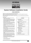
PM1D Manager V2
for Windows
Owner’s Manual
About the specifications of this software
Specifications of this software and the material given in this manual are subject to change without notice.
Copyright
Copying or distributing this software and/or this manual in part or in whole using any method without the written permission of Yamaha Corporation is prohibited.
Trademarks
Windows is a registered trademark of Microsoft Corporation in the United States and other countries.
Pentium II is a registered trademark of Intel Corporation.
Compact Flash™ is a trademark of SanDisk Corporation.
Other company names and product names are trademarks and registered trademarks of their respective owners. Symbols
such as ® and TM are not explicitly given in this document.
The illustrations and LCD screens as shown in this owner’s manual are for instructional purposes only, and may
appear somewhat different from those on your instrument.
EN
PM1D Manager V2 for Windows Owner’s Manual
Contents
About the “PM1D Manager V2 for Windows Owner’s Manual” . . . . . . . . . . . . . . . . . . . . . 3
Conventions in the “PM1D Manager V2 for Windows Owner’s Manual”. . . . . . . . . . . . . . 3
System requirements . . . . . . . . . . . . . . . . . . . . . . . . . . . . . . . . . . . . . . . . . . . . . . . . . . . . . . 3
Installing PM1D Manager . . . . . . . . . . . . . . . . . . . . . . . . . . . . . . . . . . . . . . . . . . . . . . . . . . . 4
Uninstalling PM1D Manager. . . . . . . . . . . . . . . . . . . . . . . . . . . . . . . . . . . . . . . . . . . . . . . . . 5
Using the application . . . . . . . . . . . . . . . . . . . . . . . . . . . . . . . . . . . . . . . . . . . . . . . . . . . . . . 5
Starting . . . . . . . . . . . . . . . . . . . . . . . . . . . . . . . . . . . . . . . . . . . . . . . . . . . . . . . . . . . . . 5
Exiting. . . . . . . . . . . . . . . . . . . . . . . . . . . . . . . . . . . . . . . . . . . . . . . . . . . . . . . . . . . . . . 5
Basic operation . . . . . . . . . . . . . . . . . . . . . . . . . . . . . . . . . . . . . . . . . . . . . . . . . . . . . . . 6
Initialization procedure . . . . . . . . . . . . . . . . . . . . . . . . . . . . . . . . . . . . . . . . . . . . . . . . . 6
Screens unique to PM1D Manager . . . . . . . . . . . . . . . . . . . . . . . . . . . . . . . . . . . . . . . . . . . . 7
Upper part of the display (common to all screens) . . . . . . . . . . . . . . . . . . . . . . . . . . . . 7
Lower part of the display (common to all screens). . . . . . . . . . . . . . . . . . . . . . . . . . . . . 7
Lower part of the function menu. . . . . . . . . . . . . . . . . . . . . . . . . . . . . . . . . . . . . . . . . . 8
Option popup window . . . . . . . . . . . . . . . . . . . . . . . . . . . . . . . . . . . . . . . . . . . . . . . . . 8
REMOTE CONTROL SETUP popup window . . . . . . . . . . . . . . . . . . . . . . . . . . . . . . . . . . 9
Communication between PM1D Manager and the console/engine . . . . . . . . . . . . . . . . . 10
System connection examples . . . . . . . . . . . . . . . . . . . . . . . . . . . . . . . . . . . . . . . . . . . 10
Connections . . . . . . . . . . . . . . . . . . . . . . . . . . . . . . . . . . . . . . . . . . . . . . . . . . . . . . . . 11
Data communication method . . . . . . . . . . . . . . . . . . . . . . . . . . . . . . . . . . . . . . . . . . . 12
Online operating procedure . . . . . . . . . . . . . . . . . . . . . . . . . . . . . . . . . . . . . . . . . . . . 13
Offline operating procedure . . . . . . . . . . . . . . . . . . . . . . . . . . . . . . . . . . . . . . . . . . . . 13
Cautions regarding data communication . . . . . . . . . . . . . . . . . . . . . . . . . . . . . . . . . . 13
Remote Control functionality . . . . . . . . . . . . . . . . . . . . . . . . . . . . . . . . . . . . . . . . . . . . . . . 14
Setup procedure . . . . . . . . . . . . . . . . . . . . . . . . . . . . . . . . . . . . . . . . . . . . . . . . . . . . . 14
Remote control parameter list . . . . . . . . . . . . . . . . . . . . . . . . . . . . . . . . . . . . . . . . . . . 15
Special considerations. . . . . . . . . . . . . . . . . . . . . . . . . . . . . . . . . . . . . . . . . . . . . . . . . . . . . 20
USB MIDI Driver . . . . . . . . . . . . . . . . . . . . . . . . . . . . . . . . . . . . . . . . . . . . . . . . . . . . . . . . . 22
Windows 2000 . . . . . . . . . . . . . . . . . . . . . . . . . . . . . . . . . . . . . . . . . . . . . . . . . . . . . . 22
Windows XP . . . . . . . . . . . . . . . . . . . . . . . . . . . . . . . . . . . . . . . . . . . . . . . . . . . . . . . . 22
Troubleshooting . . . . . . . . . . . . . . . . . . . . . . . . . . . . . . . . . . . . . . . . . . . . . . . . . . . . . 23
2
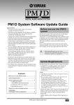
About the “PM1D Manager V2 for Windows Owner’s Manual”
About the “PM1D Manager V2 for Windows Owner’s Manual”
PM1D Manager V2 for Windows (subsequently referred
to as “PM1D Manager”) is an application program that
runs on a computer running Microsoft Windows (subsequently referred to as the “PC”), providing the same
operating environment as the software of the CS1D
(subsequently referred to as the “console”).
By using PM1D Manager, you can create various types of
settings even when you are away from the console, and
use a memory card (*) or other means to load settings
into the console at a later time. In addition, you can connect the console/engine (DSP1D-EX {DSP1D}) to your
PC, and use it to control the entire system in the same
way as from the console.
connect your PC to the console/engine, and functional
limitations of operations from the PC.
For details on basic operation in each screen, please refer
to the “CS1D Reference Manual (Software)” contained
in the CS1D Owner’s Manual.
For details on terminology and basic operation for Windows, please refer to the manual or Help files included
with Windows.
* For details on the memory cards that can be used, refer to
“CS1D Operation Manual (Basic Operation)” p.144, and
“CS1D Reference Manual (Hardware)” p.80 contained in
the CS1D Owner’s Manual.
This manual explains only items that are specific to
PM1D Manager; how to install the program, how to
Conventions in the “PM1D Manager V2 for Windows Owner’s Manual”
• Distinguishing between the controls of the console
and the knobs/buttons of the software
The names of controls on the console (switches,
encoders) are enclosed in square brackets [ ] in order
to distinguish them from the knobs and buttons that
are displayed by the software.
• Various icons
The left icon is used to indicate tips and refHint
erence pages.
Particularly important items or operations
you must use with care are marked by the
left icon.
Example: This is the same function as the DIRECT
RECALL [1]–[12] switches in the SCENE MEMORY block of the console.
System requirements
The following system is required in order to start up PM1D Manager.
• An IBM PC/AT compatible computer with at least a
Pentium II 233 Mhz or equivalent CPU (Pentium II
350 Mhz or faster is recommended)
• 64 MB or more memory (128 MB or more is recommended)
• Supported operating systems:
Microsoft Windows 2000 / Microsoft Windows XP
Home Edition / Microsoft Windows XP Professional
• Internet Explorer 4.0 or later must be installed
• A display system with resolution of at least 800 x 600
pixels and 16 bit color (SVGA, High Color)
• Hard disk free area of 10 MB or more
• Mouse or other pointing device
• CD-ROM drive
• Serial port or USB port
* You will need an RS-232-C cable (cross-wired)
not exceeding 5 meters, or a USB cable not
exceeding 3 meters.
• An ATA compatible PC CARD slot / CF (Compact
Flash) slot, or a PC CARD / CF card reader
Depending on your system and OS, a higher level of performance may be required. A higher level of performance may
also be required if you are using a notebook PC.
For the latest version of the software and driver, and for
details on operating requirements, please refer to the following URL.
http://www.yamahaproaudio.com/
3
PM1D Manager V2 for Windows Owner’s Manual
Installing PM1D Manager
This section explains how to install the PM1D Manager program.
Before you install the software, you must read the license agreement (licence_e.txt) found on the
“PM1D SYSTEM SOFTWARE” CD-ROM. You may use the software on the CD-ROM only if you
accept the terms of this license agreement.
If an older version of PM1D Manager is already
installed, you must first uninstall it. (For the uninstallation procedure, refer to p.5.)
Before you begin the installation, you must exit all applications and memory-resident programs.
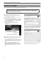
1. Insert the “PM1D SYSTEM SOFTWARE” CD-ROM
into your CD-ROM drive, and open the CD-ROM
drive from “My Computer.”
2. Inside the “WIN” folder, double-click the
“Setup.exe” icon.
The opening screen of the installer will appear.
Continue following the on-screen instructions, and
installation will be completed.
Depending on your PC system, you may be asked to restart
the system during the installation process. If so, installation
will continue automatically after you restart.
3. As directed by the instructions on the screen, click
the “Next” button as needed to proceed to the next
step.
4. When the “Select Installation Folder” screen
appears, click the Browse button if necessary, specify the installation folder, and proceed to the next
step.
4
When installation is complete, a shortcut icon will be
added to the Start menu and to the desktop.
Uninstalling PM1D Manager
Uninstalling PM1D Manager
There are two ways to uninstall PM1D Manager.
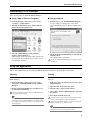
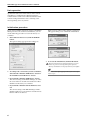
■ Using “Add or Remove Programs”
■ Using Setup.exe
1. From the Windows “Start” menu, select “Start”(“Settings”)-“Control Panel.”
1. Perform steps 1–3 of “Installing PM1D Manager.”
A screen will appear asking you to select either
“Repair PM1D Manager” or “Remove PM1D Manager.”
2. When the Control Panel opens, double-click the
“Add or Remove Programs” icon.
3. Select the “PM1D Manager” item, and click
“Remove (Change/Remove).”
PM1D Manager and related files will be deleted from
the hard disk. (For details on the procedure, refer to
your Windows manual.)
2. Check the “Remove PM1D Manager,” and click the
“Finish” button.
The software will be uninstalled.
If you selected Repair PM1D Manager, the software will not
be removed.
Using the application
This section explains how to start and exit PM1D Manager, and how to perform basic operations.
Starting
Exiting
You can use either of the following methods to start up
PM1D Manager.
You can use any of the following methods to exit PM1D
Manager.
1 From the Windows “Start” menu, select “Start”“Programs”-“YAMAHA PM1D System”-“PM1D
Manager”
1 In the lower left of the Function menu screen, click
the EXIT button.
2 Double-click the PM1D Manager icon that was created during the installation.
3 Click the “Close” button of the window.
It is not possible for multiple instances of PM1D Manager to
be running simultaneously.
2 Open the “File” menu and select “Exit.”
4 Select “Close” from the “PM1D Manager” button in
the task bar.
5 Press Alt+F4 from the keyboard.
Hint
You may find it convenient to set your screen display resolution to 800 x 600, since PM1D Manager can start up in fullscreen display mode. However in this case, the menu bar will
not be displayed.
A popup window will ask you to confirm that you want to
exit. To exit the application, click the OK button.
If you are using PM1D Manager with an 800 × 600 pixel
display, methods 2–4 cannot be used.
Hint
The next time PM1D Manager is started up, the state in
which you exited will automatically be restored.
5
PM1D Manager V2 for Windows Owner’s Manual
Basic operation
Operation in each screen is the same as on the console
itself. Refer to “CS1D Reference Manual (Software)”
contained in the CS1D Owner’s Manual. Mention of the
console’s track pad should be read as referring to the
mouse/pointing device of your PC.
Initialization procedure
If you want to initialize all current settings of the PM1D
Manager and its scene memories and libraries, you can
use the following procedure to restore the factory-set
condition.
When you press either of these buttons, a dialog box
will appear, asking you to confirm the initialization.
1. In the Function menu screen, click the OPTION
button.
The Option settings popup window will appear.
3. To execute the initialization, click the OK button.
Memories that have been initialized cannot be recovered.
Please use great care when performing this operation.
Memory initialization can be performed only when offline.
Hint
2. According to the content that you want to initialize,
click either the “Initialize All Memories” button or
the “Initialize Current Memories” button.
• If you click the “Initialize All Memories” button
The current settings of the PM1D Manager, as well as
the scene memories and the various libraries will be
initialized to the factory-set condition.
• If you click the “Initialize Current Memories” button
The current settings of the PM1D Manager will be
initialized. However, scene memories and the various
libraries will not be affected.
6
For details on the Option popup window, refer to the explanation on p.8.
Screens unique to PM1D Manager
Screens unique to PM1D Manager
This section explains the screens that differ from the console and are unique to PM1D Manager.
Upper part of the display (common to all screens)
1
2
1 Connection status
This area of the PM1D Manager screen will indicate
the status of the connection between the PC and console or engine.
•
...........Indicates that a cable is connected between the console/
engine and the PC, but
communication has not
been established.
•
...........Indicates that a cable is connected between the console/
engine and the PC, and that
communication has been
established. In this state, the
PM1D system can be controlled from the PC.
•
...........Indicates that either the
cable is not connected, or
that the other device is not
powered-on.
2 Connection destination / connection method
The connector (COM port name or USB port name)
that is selected in the Communication Port (Option
menu) of Communication Setup.
Lower part of the display (common to all screens)
1
1 RECALL button / MUTE button
Select the function of the DIRECT RECALL/MUTE
MASTER 1–12 buttons (2) from the following two
choices.
• DIRECT RECALL
You can use the DIRECT RECALL/MUTE MASTER 1–12 buttons to directly recall the scenes
assigned to direct recall numbers 1–12. For details
on how to assign a scene to a direct recall number,
refer to “CS1D Reference Manual (Software)” contained in the CS1D Owner’s Manual.
• MUTE MASTER
You can use the DIRECT RECALL/MUTE MASTER 1–12 buttons to turn muting on/off for mute
groups 1–12.
2
Hint
These two buttons have the same function as the MODE button in the MUTE GROUP ASSIGN screen of the IN DCA/
MUTE function and OUT DCA/MUTE function, and the
MODE button in the DIRECT RECALL screen of the SCENE
function.
2 DIRECT RECALL/MUTE MASTER 1–12 buttons
Depending on the setting of the RECALL button /
MUTE button (1), these buttons function either as
direct recall or mute master buttons.
These have the same function as the DIRECT
RECALL [1]–[12] switches in the SCENE MEMORY
block of the console.
7
PM1D Manager V2 for Windows Owner’s Manual
Lower part of the function menu
1
2
3
1 EXIT button
This button exits the PM1D Manager application.
This button has the same result as selecting “Exit”
from the “File” menu in the menu bar, or clicking the
“Close” button in the upper right of the PM1D Manager window.
2 OPTION button
This button is used to make communication-related
settings or to initialize the memory. When you click
this button, the Option popup window will appear.
3 ONLINE/OFFLINE button
This button initiates or terminates communication.
When the button is on, PM1D Manager is online.
When the button is off, PM1D Manager is offline.
If the console/engine and the PC are not connected
by a cable, or if communication is not possible
4
5
because the communication settings are inappropriate, the button will be grayed, and cannot be clicked.
4 ABOUT button
This button accesses a popup window that displays
the PM1D Manager version number and other information about the software.
5 REMOTE ONLINE/OFFLINE button
This button switches the Remote Control function
on/off. The button indicates ONLINE when PM1D
Manager is synchronized with the remote controller,
and OFFLINE when it is off.
If the remote controller is not connected to the PC
via USB cable, or if communication is not possible
because the communication settings are inappropriate, this button is grayed-out and cannot be clicked.
Option popup window
To open the Option popup window, click the
OPTION button located at the lower left of the function menu screen, or choose [Manager] from the
[Option] menu of the menu bar.
4
1
5
2
3
1 Communication Setup
• Communication Port
From the pulldown menu, select the port that will
be used for communication. Only COM ports 1–9
are supported.
• Meter Request
Select whether the meter movements displayed in
various screens of the console will also be displayed
in PM1D Manager. If this is turned ON, the console’s meter movements can also be viewed in
PM1D Manager.
8
• Please be aware that if Meter Request is turned ON, the
communication load will be higher.
• Depending on the PC system you are using and on the
frequency of operations on the console, the load may
exceed the allowable limit, causing communication with
the PC to be terminated for safety’s sake, and placing
PM1D Manager offline. If this occurs, turning Meter
Request OFF may solve the problem.
• If you do not require meter display, we recommend that
you turn Meter Request OFF.
2 Remote Control Setup
• Out Port
• In Port
Here you can select the USB input port (IN PORT)
and output port (OUT PORT) used for communication with the remote controller.
3 Memory Setup
Here you can reset the current PM1D Manager settings and memories/libraries to the condition in
which they were immediately following installation.
Each button has the following function.
• Initialize All Memories button
When you click this button, the current settings of
the PM1D Manager as well as the scene memories
and the various libraries will all be initialized to the
factory-set condition.
• Initialize Current Memories button
When you click this button, the current settings of
the PM1D Manager will be initialized. (However,
the scene memories and the various libraries will
Screens unique to PM1D Manager
not be affected.) The following data will be initialized.
–
–
–
–
Current scene settings
Current unit settings
Current patch settings
Name assigned in the NAME function of each
function
– Setup data (internal parameters not stored in
the scene)
Memory initialization can be performed only when
offline.
4 OK button
When you click this button, the settings that you
modified in Communication Setup will be finalized,
and the popup window will close.
5 CANCEL button
When you click this button, the settings that you
modified in Communication Setup will be discarded,
and the popup window will close.
REMOTE CONTROL SETUP popup window
To open the REMOTE CONTROL SETUP popup
window, choose [Remote Control Setup] from the
[Option] menu of the menu bar. In this window you
can make settings related to remote control (→p.14).
2
3
1
4
6
7
5
8
9
0
A
B
1 REMOTE MACHINE
When the system goes online, or when you click the
RE-SYNCHRONIZE button to establish synchronization, this field will indicate the model name
(DM2000 V2, 02R96 V2, DM1000 V2) of the remote
controller from the MIDI port. You can also select
the model name manually, even if no remote controller is connected.
2 RE-SYNCHRONIZE
This button obtains remote controller model information from the specified MIDI port. It also transmits PM1D Manager parameter data to the remote
controller.
channels of the PM1D, in units of two channels. If
you don’t want to make an assignment, choose “NO
ASSIGN.”
5 SCENE ASSIGN
Here you can select the PM1D scene memory numbers that correspond to scene memory numbers 00–
99 of the remote controller.
6 MIX ASSIGN
Here you can select the PM1D’s MIX channels that will
correspond to the remote controller’s AUX channels 1–
8 (or 1–12 on the DM2000 V2). By operating the AUX
channels of the remote controller you can control the
corresponding MIX channels of the PM1D.
7 MATRIX ASSIGN
Here you can select the PM1D’s MATRIX channels
that will correspond to the remote controller’s BUS
channels 1–8. By controlling the BUS channels of the
remote controller you can control the corresponding
MATRIX channels of the PM1D.
8 STEREO ASSIGN
Here you can select the PM1D’s STEREO channel
(STEREO A or B) that will correspond to the remote
controller’s STEREO channel.
9 ATT
This selects whether ATT operations on the remote
controller will control the PM1D’s ATT or its HA
GAIN (or digital gain).
0 IN EQ LOW
This selects whether LOW band EQ operations on an
input channel of the remote controller will control
the PM1D’s LOW band EQ or its HPF.
3 ONLINE/OFFLINE indication
This will indicate ONLINE when communication
with the remote controller has been established.
A OUT EQ
This selects the set of four bands on the PM1D’s
input channel EQ that will be controlled by operating the four-band EQ of an output channel on the
remote controller.
LOW: SUB LOW, LOW, LOW MID, MID bands
HIGH: LOW MID, MID, HIGH MID, HIGH bands
4 CH ASSIGN
Here you can assign the correspondence between
input channels of the remote controller and input
B EXIT
Closes the REMOTE CONTROL SETUP popup window.
9
PM1D Manager V2 for Windows Owner’s Manual
Communication between PM1D Manager and the console/engine
If you connect the console/engine and the PC, you can use PM1D Manager as a supplementary controller for
the system.
• “Online” refers to a state in which the console/
engine and the PC are connected by a cable, and data
can be transferred to control the device immediately.
• “Offline” refers to a state in which the console/
engine and the PC are not connected by a cable and
therefore are unable to communicate, or a state in
which the cable is connected but communication has
not begun.
In the online state, parameters (with some exceptions) will be linked between the console/engine and
the PC, allowing PM1D Manager to monitor the
state of the system, operate it remotely, and act as a
substitute in the event of device failure. The material
that follows will explain various ways of setting up
the system, and how data communications can be
established and terminated.
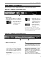
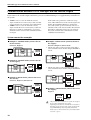
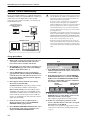
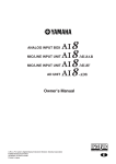
System connection examples
■ Example 1: Standard mode (connect the PC
to the console)
Console×1, Engine×1
ENGINE
(DSP1D)
CONSOLE
(CS1D)
• The PC can only be connected to the engine that is
selected in Mirror mode. In this example, ENGINE A
is used.
ENGINE A
(DSP1D)
■ Example 2: Standard mode (connect the PC
to the engine)
ENGINE
(DSP1D)
CONSOLE
(CS1D)
■ Example 4: Mirror mode (connect the PC to
the engine)
Console×1, Engine×2 (mirror mode)
CONSOLE
(CS1D)
ENGINE B
(DSP1D)
• The PC can only be connected to the engine that is
selected in Mirror mode. In this example, ENGINE B
is used.
ENGINE A
(DSP1D)
■ Example 3: Mirror mode (connect the PC to
the console)
Console×1, Engine×2 (mirror mode)
CONSOLE
(CS1D)
ENGINE B
(DSP1D)
ENGINE A
(DSP1D)
CONSOLE
(CS1D)
ENGINE B
(DSP1D)
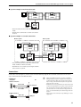
■ Example 5: Normal mode (connect the PC to
the engine)
Engine×1
ENGINE
(DSP1D)
• Only one PC can be connected to a system. It is not possible to connect multiple PC’s to a system.
• Depending on the device to which the PC is connected, or
depending on the structure of the system, the functionality of PM1D Manager may be partially limited. For
details, refer to “PC connections in a system that includes
a console” (→p.21).
10
Communication between PM1D Manager and the console/engine
■ System example 6: Dual Console mode
PC1
Console1
(CS1D)
PC2
Console2
(CS1D)
Engine
(DSP1D)
• You can connect and use either PC1 or PC2 (not
both).
• Even if a PC is connected to console 2, it cannot
be used.
■ System example 7: Cascade connection
Master system
Slave system
PC1
PC3
Console
(CS1D)
PC2
Console
(CS1D)
DSP1D
(ENGINE)
Engine
(DSP1D)
cascade
Engine
(DSP1D)
PC4
• You can connect and use either PC1 or PC2 (not
both), and PC3 or PC4 (not both).
• Even if there is no console, just an engine and PC
can be used as a system.
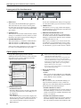
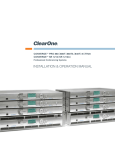
Connections
Connect the console/engine to your PC as shown in the following diagram. You can make connections in one of two
ways: serial connection or USB connection.
CS1D/DSP1D
rear panel
PC
1. Serial connection
RS-232-C
Serial cable
PC serial port
D-sub 9-pin (male⇔male)
cross cable
2. USB connection
USB
USB cable
• When using USB connections, you must exit PM1D
Manager before you power-on/off the console/engine or
connect/disconnect cables. If you perform these actions
before exiting, communication may become impossible
until you restart your PC.
• USB connection is not guaranteed to be faster than serial
connection. Depending on your system, serial connection
may provide faster and more stable communication. If
you were able to use serial connection with previous versions, we recommend that you continue using serial connection.
• When using a serial connection, only COM ports 1–9 are
supported.
USB port
11
PM1D Manager V2 for Windows Owner’s Manual
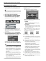
Data communication method
Use the following procedure to initiate communication.
1. Connect your PC to the console or engine, using
either a serial connection or a USB connection.
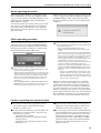
6. In the Function menu screen, click the ONLINE/
OFFLINE button.
The following popup window will appear.
Hint
When using USB connection, you must first install the USB
driver. If you have not yet installed the USB driver, do so as
described in “USB driver installation” (→p.22).
2. Power-on the connected console/engine.
3. Start up PM1D Manager, and click the OPTION
button located in the lower left of the Function
menu screen or select [Manager Option] from the
[OPTION] menu in the menu bar.
Click
4. In the Communication Port field, select the port
that you will be using, and click the OK button.
When using a serial connection, only COM ports 1–9
are supported.
5. If the system includes a console, click the PERMIT
button in the PC CONNECTION area of the console’s
SYSTEM CONNECTION screen. This will allow a PC
connection with the connected console/engine.
In this popup window you can select one of the following two connection modes.
• UPLOAD
The current settings of PM1D Manager will be
transmitted to the console/engine, and then synchronized operation will begin.
• DOWNLOAD
The current settings of the console/engine will be
transmitted to PM1D Manager, and then synchronized operation will begin.
Whether PM1D Manager is online or offline can be
verified by the state of the ONLINE/OFFLINE button in the Function menu screen.
Offline (connection not possible)
Offline (connection possible)
Online
In a state in which it is not possible to initiate communications, the OFFLINE/ONLINE button will be grayed, and
cannot be clicked. In this case, please check the cable connections and settings.
For details, refer to “CS1D Reference Manual (Software)” contained in the CS1D Owner’s Manual SYS/
W.CLOCK function.
Hint
• If you are using Mirror mode, you can communicate only
with the selected engine A or B. The PERMIT button for
the unused engine cannot be turned on from the PC
CONNECTION screen.
• If you are using Dual Console mode, you can communicate only with console 1. The console 2 PERMIT button
will not appear in the PC CONNECTION screen.
Also, you cannot operate the various PERMIT buttons
from console 2.
• Only one PC can be connected to a system. It is not possible to connect multiple PC’s to a system. The PERMIT
button in the PC CONNECTION screen can be turned
on either (not both) for the console or the engine that is
being used (ENGINE A or B).
If you are using cascade connection, master and slave are
handled separately, so this is considered as two systems.
12
When you click either UPLOAD or DOWNLOAD in the
“CONNECTION” popup window to select the connection
mode, please check the following points.
• In the console’s SYS/W.CLOCK screen PC CONNECTION area, make sure that the PERMIT button of the
device connected to the PC is turned on.
• Make sure that no popup window is displayed in the
screen of the console.
• Make sure that no file is being loaded on the console.
• Make sure that time code is not running in the system.
• Auto fading or manual fading are not in progress.
If any of the above conditions are not satisfied, a popup
window will appear, informing you that the PC cannot be
connected to the other device, and the connection procedure
will be aborted at step 4 above.
Communication may become unstable if the cable is too
long. Use a cable no longer than 5 meters for serial connection, or a cable no longer than 3 meters for USB connection.
If time code is running when you attempt to initiate communication, communication will be aborted. Transmit time
code after switching to online mode.
Communication between PM1D Manager and the console/engine
Online operating procedure
If the console/engine and PC are connected correctly,
and communication is possible, the OFFLINE symbol
(see p.8) shown at the top of the PM1D Manager screen
will change to the ONLINE symbol, indicating that
PM1D Manager is online.
Now the PC and the entire system will be operate in tandem, and you can use PM1D Manager for supplementary control of the system. However, some operations
and parameters will not be linked, so please read p.20
and 21 for details.
While an important operation is being performed on the
console, a popup window like the following will appear,
and PM1D Manager will be temporarily inoperable.
Please wait until the operation on the console has been
completed.
Offline operating procedure
To break communication between the online the console/engine and the PC, click the OFFLINE/ONLINE
button in the lower part of Function menu screen. The
following popup window will appear, so click the OK
button and you will switch to offline mode.
Immediately before PM1D Manager transitions from
offline to online, all data is automatically backed up. (This
is referred to as the recovery point.)
When returning to the offline state, the scene memories and
all library data will return to the recovery point, regardless
of the reason that the system went offline. In other words,
the current scene will be maintained from its online state,
but the scene memories and all library data will not be
maintained.
Also, the DIRECT RECALL / MIDI CTRL CHANGE / TC
EVENT functions will normally not be recovered. Be aware
that this may produce settings that you do not expect.
Even if the user does not manually switch to the offline
state, communication will forcibly be switched offline when
one of the following occurs.
• When you exit PM1D Manager while online
• When permission for PC connection is canceled on the
console
• When the console switches between engine A/B while the
PC is connected to the engine (system example 4 on p.10)
• When a console is connected to a system that consisted of
only an engine and a PC (system example 5 on p.10)
• When the cable connection is accidentally broken, or if a
communication time-out occurs for any reason (*)
• When processing cannot be performed in time because of
an excessive amount of data being transferred (*)
• When the user cancels during an upload or download (*)
• When the SYSTEM CONFIGURATION of the console is
switched to console 2 while the console and PC are still
online (*)
* In these cases, PM1D Manager will attempt to return
all data on the PC to the recovery point, but it is possible that the data has already been destroyed. You can
either reload the data, or re-connect to the device with
which you were communicating.
If the PC is connected to the engine in a system that
includes a console (system example 4 on p.10), and if
communication between the console and engine is broken for some reason, the scene memory and all library
data will return to the recovery point. If you are using
the PC as a backup for the console, we recommend that
you load the PC with same data as the console while the
PC is still offline, so that the recovery point will be the
same state as the console. Then make the connection.
Cautions regarding data communication
■ You should exit all Windows application software
and resident software. Communication may be
unstable if you fail to do so.
■ If you are using a notebook PC, you may require a
higher level of performance than described for the
minimum level of system configuration (→p.3).
■ Do not perform the following operations while communication is occurring. Doing so may cause communication to be broken.
• Suspend/resume operations
• Starting up a screen saver (including automatic
startup by timer)
• Connecting or disconnecting a memory card or
USB device, etc.
■ If you are using a notebook PC, communication may
become unstable because of power-management settings in the Windows control panel or power-management settings specific to your CPU (SpeedStep
[Intel CPUs], PowerNow! [AMD CPUs], LongRun
[Transmeta CPUs]). Please turn such functionality
off, and use the notebook PC with its AC power
adaptor connected.
13
PM1D Manager V2 for Windows Owner’s Manual
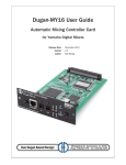
Remote Control functionality
If you connect PM1D Manager to a Yamaha digital mixer
(DM2000 V2, 02R96 V2, and DM1000 V2) via USB, you
will be able to use the digital mixer (subsequently
referred to as the “remote controller”) to remotely control the PM1D system.
Yamaha digital mixer
(DM2000 V2, 02R96 V2,
DM1000 V2)
PM1D Manager
USB
USB/RS-232C
PM1D V2 system
Engine
DSP1D/DSP1D-EX
• The digital mixers that can be used for remote control are
only the DM2000 V2, 02R96 V2, and DM1000 V2, and
each must be running system software V2. Remote control from other mixers is not possible.
• If you use a remote control device, the scene data and
setup data stored in the digital mixer (DM2000 V2,
02R96 V2, DM1000 V2) will be rewritten. Please back up
all of your digital mixer’s data to a computer or other
external media before you use the remote control functions. For details on how to back up, refer to the manual
of your digital mixer.
• The PM1D system’s parameters that can be remotely controlled are the HA GAIN or digital gain, ATT, EQ, GATE,
COMP, MIX SEND, FADER, ON, SURROUND, CUE/
SOLO ON, DCA, and scene parameters. For details, refer
to the remote control parameter list (→p.15).
• Parameters that do not match between the remote controller and the PM1D will be controlled to the value that
is closest to the parameter value that was operated. This
means that the actual value may differ from the displayed
value.
Console CS1D
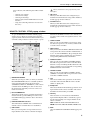
Setup procedure
1. Make a USB or serial connection between the console/engine and the PC, and a USB connection
between the remote controller and the PC.
2. In the SETUP screen of the remote controller, go to
the MIDI/HOST page and set the Studio Manager
PORT to “USB” and the ID to “1.”
3. Start up PM1D Manager, and open the Option
popup window either by clicking the OPTION button in the lower left of the function menu screen or
by choosing [Manager Option] from the [Option]
menu in the menu bar.
4. In the Option window, make the port settings
shown below, and click [OK].
Communication Port: Select the port that you will
use to communicate with the console/engine.
Remote Control Setup: Select the USB input port
(IN PORT) and output port (OUT PORT) used to
communicate with the remote controller. If the connection with the console/engine is also a USB connection, be careful that you don’t select the console/
engine port by mistake.
5. From the menu bar, choose [Option] menu →
[Remote Control Setup] to open the REMOTE
CONTROL SETUP popup window.
6. In the REMOTE CONTROL SETUP window, select
the model name of the remote controller you’re
using in the REMOTE MACHINE field.
14
Click
7. In the REMOTE CONTROL SETUP window, make
channel assignments for the remote controller and
for the PM1D (→p.9).
8. In the function menu screen, click the REMOTE
ONLINE/OFFLINE button (or the RE-SYNCHRONIZE button in the REMOTE CONTROL SETUP
windows) to enable Online status for communication with the remote controller.
ONLINE/
OFFLINE button
REMOTE ONLINE/
OFFLINE button
9. In the function menu screen, click the ONLINE/
OFFLINE button to enable Online status for communication with the console/engine.
This completes preparations for remote control.
10. In this state, operating the parameters on the
remote controller will also control the corresponding parameters on the PM1D.
For details on the parameters supported for remote
control, refer to the remote control parameter list
(→p.15).
Remote Control functionality
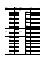
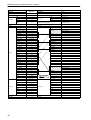
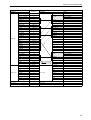
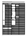
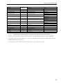
Remote control parameter list
PM1D
Parameter
Direction*1
Remote Controller
Parameter
Input Fader
↔
Input Fader
Input On
↔
Input On
Input Att
↔
Input HA Gain
↔
Input EQ
----
Ignored ←
----
Ignored ←
EQ TYPE
When HPF
Low Q
↔
When other than L.SHELF or HPF
HPF F
↔
When IN EQ LOW = HPF
Low F
↔
Low G
↔
Low G
When IN EQ LOW = LOW
HPF on
↔
Low G (HPF On)
When IN EQ LOW = HPF
Low Mid Q
↔
Low Mid Q
Low Mid F
↔
Low Mid G
↔
Hi Mid Q
↔
Hi Mid Q
Hi Mid F
↔
Hi Mid F
Hi Mid G
↔
Hi Mid G
Hi LPF
↔
Hi H.SHELF
↔
Hi Q
↔
Hi F
↔
Hi Mid F
↔
Hi Mid G
On
On
----
Input Surround
When ATT mode = HA GAIN
↔
Hi LPF
Input Comp
When ATT mode = ATT
Input Att
Low L.SHELF
Hi G
Input Gate
Notes
Low Q
Low F
Low Mid G
When LPF
Hi Q
LPF On
On
↔
On
Ignored ←
Link
Ignored ←
KeyIn
Ignored ←
KeyAUX
Ignored ←
KeyCh
Type
↔
Attack
↔
Attack
Range
↔
Range
Hold
↔
Hold
Decay
↔
Decay
Threshold
↔
Threshold
Input Gate
Type
----
Ignored ←
On
↔
On
----
LocComp
Ignored ←
Link
Type
↔
Type
Attack
↔
Release
↔
Ratio
↔
Ratio
Gain
↔
Gain
Knee
↔
Knee
Threshold
↔
Threshold
Link
↔
When H.SHELF
When other than H.SHELF or LPF
↔
Ignored ←
When IN EQ LOW = LOW
Low Mid F
Input EQ
Ignored ←
----
When L.SHELF
Input Comp
Attack
Release
Direction
Link
Pattern Link
↔
PattLink
Surround LFE
↔
LFE
Divergence F
↔
Div
LR Pan
↔
FR Pan
↔
X
Input Surround
Y
----
Ignored ←
Width
----
Ignored ←
Depth
----
Ignored ←
OffsetX
----
Ignored ←
OffsetY
Divergence Link
↔
DivLink
Divergence R
↔
DivRear
15
PM1D Manager V2 for Windows Owner’s Manual
PM1D
Parameter
Direction*1
Remote Controller
Parameter
Notes
Input to Stereo Pan
↔
Input Channel Pan
Input to Stereo On
↔
Routing Stereo
On
↔
Pre/Post
↔
Level
↔
Pan (only if mix
pair)
↔
Aux Pan (only if aux pair)
Mix Fader
↔
Aux Fader
Mix On
↔
Aux On
Ignored ←
Aux EQ
Mix Send
----
to aux1/2–11/12 *2
EQ TYPE
↔
SubLow Q
↔
SubLow F
↔
Low F
↔
Low G
Ignored ←
SubLow On
→ Ignored
When HPF
Low Q
HPF On
----
Low Q
↔
Low Mid Q
Low F
↔
Low Mid F
Low G
↔
Low Mid G
Low On
→ Ignored
----
Low Mid Q
↔
Hi Mid Q
Low Mid F
↔
Hi Mid F
Low Mid G
↔
Hi Mid G
Low Mid On
→ Ignored
----
Mid Q
↔
----
Mid F
↔
----
Mid G
↔
----
Mid On
→ Ignored
----
Hi Mid Q
↔
----
Hi Mid F
↔
----
Hi Mid G
↔
----
Hi Mid On
→ Ignored
----
Hi LPF
↔
Hi H.SHELF
↔
Hi Q
↔
Hi F
↔
Hi Mid F
↔
Hi Mid G
----
Ignored ←
Hi On
→ Ignored
When L.SHELF
When other than L.SHELF or HPF
When LPF
Hi Q
When H.SHELF
When other than H.SHELF or LPF
LPF On
Low mode
High mode
----
On
↔
----
Ignored ←
On
↔
On
----
Ignored ←
Link
Type
↔
Type
Attack
↔
Release
↔
Ratio
↔
Ratio
Gain
↔
Gain
Knee
↔
Knee
Threshold
↔
On
LocComp
Aux Comp
Attack
Release
Threshold
Matrix Fader
↔
Bus Fader
Matrix On
↔
Bus On
16
to aux1–12 *2
SubLow L.SHELF
Hi G
Mix Comp
to aux1–12 *2
Level
↔
----
to aux1–12 *2
Pre/Post
SubLow HPF
SubLow G
Mix EQ
On
Aux Send
Remote Control functionality
PM1D
Parameter
----
Notes
Bus EQ
EQ TYPE
↔
SubLow L.SHELF
↔
SubLow Q
↔
SubLow F
↔
Low F
↔
Low G
When HPF
Low Q
Ignored ←
SubLow On
→ Ignored
----
Low Q
→ Ignored
Low Mid Q
Low F
→ Ignored
Low Mid F
Low G
→ Ignored
Low Mid G
Low On
→ Ignored
HPF On
----
Low Mid Q
↔
Hi Mid Q
Low Mid F
↔
Hi Mid F
Low Mid G
↔
Hi Mid G
Low Mid On
→ Ignored
----
Mid Q
→ Ignored
----
Mid F
→ Ignored
----
Mid G
→ Ignored
----
Mid On
→ Ignored
----
Hi Mid Q
↔
----
Hi Mid F
↔
----
Hi Mid G
↔
----
Hi Mid On
→ Ignored
----
Hi LPF
↔
Hi H.SHELF
↔
Hi Q
↔
Hi F
↔
Hi Mid F
↔
Hi Mid G
Hi LPF
Ignored ←
Hi On
→ Ignored
When L.SHELF
When other than L.SHELF or HPF
SubLow HPF
Hi G
Matrix Comp
Ignored ←
Remote Controller
Parameter
SubLow HPF
SubLow G
Matrix EQ
Direction*1
When LPF
Hi Q
When H.SHELF
When other than H.SHELF or LPF
LPF On
Low mode
High mode
----
On
↔
----
Ignored ←
On
↔
On
----
On
LocComp
Ignored ←
Link
Type
↔
Type
Attack
↔
Release
↔
Bus Comp
Attack
Release
Ratio
↔
Ratio
Gain
↔
Gain
Knee
↔
Knee
Threshold
↔
Threshold
Stereo Fader
↔
Stereo Fader
Stereo Bal
↔
Stereo Bal
Stereo On
↔
Stereo On
17
PM1D Manager V2 for Windows Owner’s Manual
PM1D
Parameter
----
EQ TYPE
↔
↔
SubLow Q
↔
SubLow F
↔
Low F
↔
Low G
When HPF
Low Q
SubLow HPF
Ignored ←
SubLow On
→ Ignored
----
Low Q
→ Ignored
Low Mid Q
Low F
→ Ignored
Low Mid F
Low G
→ Ignored
Low Mid G
Low On
→ Ignored
HPF On
----
Low Mid Q
↔
Hi Mid Q
Low Mid F
↔
Hi Mid F
Low Mid G
↔
Hi Mid G
Low Mid On
→ Ignored
----
Mid Q
→ Ignored
----
Mid F
→ Ignored
----
Mid G
→ Ignored
----
Mid On
→ Ignored
----
Hi Mid Q
↔
----
Hi Mid F
↔
----
Hi Mid G
↔
----
Hi Mid On
→ Ignored
----
Hi LPF
↔
Hi H.SHELF
↔
Hi Q
↔
Hi F
↔
Hi Mid F
↔
Hi Mid G
Hi LPF
Ignored ←
Hi On
→ Ignored
When LPF
Hi Q
LPF On
Low mode
High mode
----
↔
----
Ignored ←
On
↔
On
----
Ignored ←
Link
Type
↔
Type
Attack
↔
Release
↔
Ratio
↔
Ratio
Gain
↔
Gain
Knee
↔
Knee
Threshold
↔
On
LocComp
Stereo Comp
Attack
Release
Threshold
↔
Input Pair
Mix Pair
↔
Aux Pair
Matrix Pair
↔
Bus Pair
Word Clock select
Input CH Select
↔
Output CH select
↔
Input Cue
↔
Input Solo
Mix Cue
↔
Aux Solo
Matrix Cue
↔
Bus Solo
Stereo Cue
↔
Stereo Solo
Cue mode
↔
Solo Sel mode
Cue Interruption
↔
Solo Interruption
DCA Fader 1-8
↔
Input Fader Group Fader
DCA Fader 9-12
↔
Output Fader Group Fader
DCA Mute 1-8
↔
Input Fader Group On
DCA Mute 9-12
↔
Output Fader Group On
Mute Master 1-8
↔
Input Mute Master
Input CH Select
Aux CH select
Bus CH select
Stereo select
18
When H.SHELF
When other than H.SHELF or LPF
On
Ignored ←
When L.SHELF
When other than L.SHELF or HPF
Input Pair
Word Clock status
Notes
Stereo EQ
SubLow L.SHELF
Hi G
Stereo Comp
Ignored ←
Remote Controller
Parameter
SubLow HPF
SubLow G
Stereo EQ
Direction*1
Specify 48k if PM1D is unlocked
Remote Control functionality
PM1D
Parameter
Direction*1
Remote Controller
Parameter
Mute Master 9-12
↔
Output Mute Master
Surround Mode
↔
Surround Mode
Input CH Name (Short)
↔
Input CH Name (Short)
Input CH Name (Long)
↔
Input CH Name (Long)
Mix CH Name (Short)
↔
Aux CH Name (Short)
Mix CH Name (Long)
↔
Aux CH Name (Long)
Matrix CH Name (Short)
↔
Bus CH Name (Short)
Matrix CH Name (Long)
↔
Bus CH Name (Long)
Stereo CH Name (Short) L-side only
↔
Stereo CH Name (Short)
Stereo CH Name (Long) L-side only
↔
Stereo CH Name (Long)
Scene Now #
↔
Scene Now
Scene Last #
↔
Scene Last
Scene Recall Function
←
Scene Recall Function
Scene Clear Function
↔
Scene Clear Function
Scene Store Function
↔
Scene Store Function
Scene Title
↔
Scene Title
Scene Protect
↔
Scene Protect
Notes
column1–4
column1–8
column9–16 *3
column1–4
column1–8
column9–16 *3
column1–4
column1–8
column9–16 *3
column1–4
column1–8
column9–16 *3
*1. Indicates the direction(s) in which remote control is supported.
↔ .................... Commands can be transmitted and received in either direction between the PM1D and the remote controller.
Ignored ← ...... This is a parameter not found on the PM1D, so the command will be ignored if it is received from the remote controller.
→ Ignored ...... This is a parameter not found on the remote controller, so the command will be ignored if it is received from the PM1D.
*2. AUX channels on units other than the DM2000 V2 are 1–8. The corresponding MIX channels will depend on the MIX ASSIGN settings in the
REMOTE CONTROL SETUP popup window.
*3. Since the PM1D does not have column 9–column 16, the data is fixed as “ ” (space) on the remote controller.
19
PM1D Manager V2 for Windows Owner’s Manual
Special considerations
This section notes various things you should be aware of concerning the parameters and operations in each
screen.
■ PREFERENCE switch
CONFIRMATION
ON/OFF
WARNING MESSAGES
ON/OFF
These settings are not linked
with the console in the system,
and therefore must be set individually.
GATE/COMP GR
METER ON/OFF LINK
INTERNAL
CALENDAR/CLOCK
Since this indicates the date of
the PC, it is not linked with the
console. Make this setting in
the Windows [Control Panel][Date and time].
Others
These functions are specific to
the console, and do not exist in
PM1D Manager.
The SELECTED CH field in the
AUTO DISPLAY area is not
shown in PM1D Manager, but
is always enabled.
■ SELECTED INPUT CHANNEL / SELECTED
OUTPUT CHANNEL
These settings are not linked with the console in the
system, and can be set independently.
If you recall a scene for which a fade time setting has
been specified, the faders/pan in PM1D Manager will
immediately indicate the value that is to be reached
after fading, and will stop there. However, if you
operate a fader while the fade time is being executed,
the fade for that channel will be cancelled, and the
fader will remain at the position to which you moved
it.
If the PC and engine alone are online, Fader Start
control is performed from PM1D Manager. Thus,
even if the scene has a fader time setting, Fader Start
will function immediately after scene recall occurs.
■ MIDI program changes / control changes
The MIDI ports of the PC cannot be used as MIDI
inputs/outputs for the PM1D Manager software.
■ TC events
The setting can always be made, but since operation
in response to incoming time code is performed by
the console itself, the following restrictions apply.
Hint
You can switch the channel directly by left-clicking or rightclicking SELECTED INPUT CHANNEL / SELECTED
OUTPUT CHANNEL field located in the lower part of the
screen.
■ MODULE FLIP / FADER FLIP
These functions are specific to the console, and do
not exist in PM1D Manager.
■ PREVIEW mode on/off (MEMORY screen)
This is not linked with the console in the system, and
can be set independently.
Offline
Fixed at Preview mode = off
Online
Preview mode can be turned
on/off
Function is valid (*)
Offline
Online
Console exists in
the system
Function is valid
Console does not
exist in the system
Function is invalid (*)
(*) It will not be possible to operate the EVENT RECALLING button or TIME CODE IN button in the TC
EVENT screen (MIDI/GPI/TC function).
It is not possible to output time code directly from the
PC. Nor can the CAPTURE button operated from the
PC.
■ Meters
The function of the meters will change as follows,
depending on the online/offline status of PM1D
Manager, and on the presence or absence of a console.
No meters will be displayed.
Offline
If you exit PM1D Manager with Preview mode turned
on, the content (Preview mode content) that was displayed when you last exited) will be recovered. However
at this time, the PREVIEW button will be turned off. In
the same way if you go offline with Preview mode
turned on, the contents that had been Preview-displayed when online will be handled as Preview mode =
off.
■ Fade time operation
Due to functional limitations, realtime control and
monitoring of the fade time is not possible on PM1D
Manager. Thus, the manual fade function cannot be
used.
20
Online
Console exists in
the system
Some meters will not
be displayed. (*)
Console does not
exist in the system
All meters will be displayed.
(*) Due to functional limitations, some meter data can be
displayed only for a single selected channel within the
system. In such cases, the channel selected on the console will be given priority.
In order to avoid inconsistencies due to the fact that
the selected channel is not linked between the PC and
console, this type of meter will not be displayed on the
PC.
Also, the ∑ meter will not be displayed on the PC.
Special considerations
■ KEY IN CUE button (GATE PRM screen)
Operation will change as follows, depending on the
online/offline state of PM1D Manager and on the
presence or absence of a console.
Operable
Offline
Online
Console exists in
the system
Not displayed. (*)
Console does not
exist in the system
Operable
(*) In order to avoid inconsistencies due to the fact that
the selected channel is not linked between the PC and
console, this will never be displayed on the PC.
■ SYSTEM CONFIGURATION in screens such as
the SYS/W.CLOCK function SYSTEM CONNECTION screen and ENGINE SELECT
Operation will change as follows, depending on the
online/offline state of PM1D Manager and on the
presence or absence of a console.
Offline
Operable
Online
Not operable
For reasons of safety, the above settings will not be
reflected in the connected device even if you select
UPLOAD when initiating the connection. (Conversely,
the setting of the connected device will be reflected on
the PC.)
■ Simultaneous use with other serial communication software such as PM1D LOAD
PM1D Manager cannot be used simultaneously on
the same port as other serial communication software such as PM1D LOAD.
Please exit all such software before starting PM1D
Manager.
■ PC connections in a system that includes a
console
If the system includes a console, connections with
the PC are limited in the following ways.
• When online, the following items cannot be operated
from PM1D Manager. (However, they can be operated from the console.)
– Load/save operations in the LOAD/SAVE screen
(UTILITY function)
– STORE, TITLE EDIT, and APPLY EDIT button
operations, changes to Scene Link, and Scene
Sort in the MEMORY screen (SCENE function)
– STORE, TITLE EDIT, and APPLY EDIT button
operations in the various libraries
– Startup/viewing/operations in the UNIT,
PATCH, and NAME library popup windows
■ UNIQUE No. in the SYS/W.CLOCK function
SYSTEM CONNECTION screen
Operation will change as follows, depending on the
online/offline state of PM1D Manager and on the
presence or absence of a console.
Not displayed
Offline
Online
Console exists in
the system
Displayed / not settable
Console does not
exist in the system
Displayed / settable
■ DIGITAL I/O connector select button and PC
CONNECTION area in the SYS/W.CLOCK
function SYSTEM CONNECTION screen
These functions are specific to the console, and do
not exist in PM1D Manager.
■ MUTE MODE buttons in the lower part of the
display / DIRECT RECALL screen / MUTE
GROUP ASSIGN screen
These are not linked with the console in the system,
and can therefore be operated independently.
■ LOAD/SAVE screen
The number of characters that can be used in a filename is eight characters plus the filename extension
(.PM1). If this number of characters is exceeded, the
file cannot be recognized by PM1D Manager, and the
file may not be displayed in the file list. Please be
aware of this if you modify the filename in Windows.
21
PM1D Manager V2 for Windows Owner’s Manual
USB MIDI Driver
If you are connecting the console/engine to a USB port on your PC, you’ll need to install the Yamaha USB
driver. If this driver is already installed, or if you will be using a serial connection (RS-232-C connector), you
do not need to install the USB driver.
PC
The procedure for installing the Yamaha USB driver
depends on the version of Windows that you are using.
PM1D
Manager
USB cable
Driver
Console/engine
(CS1D/DSP1D)
Windows 2000
1. Start your PC and Windows, log on as the Administrator, and then insert the included CD-ROM into
your PC’s CD-ROM drive.
2. Go to My Computer→Control Panel→
System→Hardware→Driver Signing→File Signature Verification, select “Ignore-Install all files,
regardless of file signature,” and then click OK.
3. Power-off the console/engine, and use a USB cable
to connect the console/engine to the PC.
The USB connector of the console/engine is located
in the PC CONTROL section of the rear panel.
4. Turn on the console/engine.
The Found New Hardware Wizard appears.
5. Click Next.
6. Select “Search for a suitable driver for my device
(Recommended),” and then click Next.
7. In the subsequent window, select “CD-ROM
drives” only, and then click Next.
You may be prompted to insert your Windows CD-ROM.
Do not insert it! Click OK, and in the “Copy files from” section of the subsequent dialog box, enter “D:\USBdrv2k_”
(replacing “D” with the drive letter of your CD-ROM
drive), and then click OK.
The driver is installed, and the message “Completing
the Found New Hardware Wizard” appears.
8. Click Finish, and then restart your PC.
Windows XP
1. Power-on the PC, and when Windows starts up, log
in using an account with Administrator privileges.
2. Insert the included CD-ROM into your PC’s CDROM drive.
3. Click the Start button, and then click Control
Panel.
If the Control Panel window appears as shown
below, click “Switch to Classic View” on the left side
of the window in order to see all the control panels.
4. Go to System Hardware→Driver signatures→
Driver signature options, select “Ignore-Install
software without asking for confirmation,” and
then click OK.
5. Click OK to close the System Properties window,
and then click the Close button to close the Control
Panel window.
6. Power-off the console/engine, and use a USB cable
to connect the console/engine to the PC.
The USB connector of the console/engine is located
in the PC CONTROL section of the rear panel.
7. Turn on the console/engine.
The Found New Hardware Wizard appears.
8. Select “Install software automatically (recommended) (I),” and then click Next.
The driver is installed, and the message “Completing
the Found New Hardware Wizard” appears.
9. Click Finish, and then restart your PC.
22
USB MIDI Driver
Troubleshooting
Cannot control the console/engine via USB
• Have you installed the Yamaha USB MIDI driver (see
page 22)?
• Is the USB cable connected correctly (see page 11)?
• Have you correctly set the Communication Port in
the Option menu of PM1D Manager?
Cannot install the Yamaha USB MIDI Driver
• Is the USB cable connected correctly (see page 11)?
Try disconnecting the USB cable, and then reconnecting it.
• Is USB enabled?
When the console/engine is connected to your PC for
the first time, if the Add New Hardware Wizard
doesn’t appear, it may be because your PC’s USB
controller is disabled. To check this, open the System
control panel, click the Device Manager tab, and
check for any crosses (x) or exclamation marks (!)
next to the “Universal Serial Bus controllers” and
“USB Root Hub” items. If these items do have these
marks next to them, your USB controller is disabled.
For information on enabling your USB controller,
refer to your PC’s documentation.
• If for some reason installation of the Yamaha USB
Driver fails, the CS1D/DSP1D may be registered as
an unknown device and you may not be able to reinstall the driver until the unknown device is deleted.
In this case, open the System control panel, click the
Device Manager tab, and select the “View devices by
connection” option. If an item called “Other devices”
appears in the list, click it. If there’s an item called
“Unknown device,” select it and then click the
Remove button. Disconnect the USB cable, then
reconnect it, and now try installing the driver again.
Improving performance
• If your PC seems unresponsive, make sure it satisfies
the system requirements (see page 3).
• Quit any other applications that you are not using.
Cannot suspend or resume your PC
• Suspend will not work if there are any MIDI applications open.
• Windows 2000: Depending on the USB controller,
etc., on some systems, suspend and resume may not
work properly. If the console/engine stops responding, try disconnecting and reconnecting the USB
cable.
Cannot communicate with the PM1D system
• Turn off power conservation settings on your computer (e.g., suspend, sleep, standby, hibernate). If
power conservation is enabled, communication may
be impossible or the connection may fail during
operation.
23
U.R.G., Pro Audio & Digital Musical Instrument Division, Yamaha Corporation
© 2002 Yamaha Corporation
WF52700 806IPAPx.x-0xA1
Printed in Japan