1
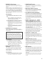
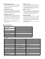
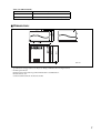
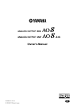
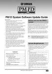
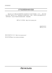
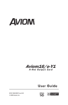
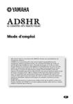
-EX
Owner’s Manual
V480360 R0 1 IP 16
200 AP Printed in Japan
E
FCC INFORMATION (U.S.A.)
1. IMPORTANT NOTICE: DO NOT MODIFY THIS UNIT! This product, when installed as indicated in the instructions contained in this manual, meets FCC
requirements. Modifications not expressly approved by Yamaha may void your authority, granted by the FCC, to use the product.
2. IMPORTANT: When connecting this product to accessories and/or another product use only high quality shielded cables. Cable/s supplied with this product MUST
be used. Follow all installation instructions. Failure to follow instructions could void your FCC authorization to use this product in the USA.
3. NOTE: This product has been tested and found to comply with the requirements listed in FCC Regulations, Part 15 for Class “B” digital devices. Compliance with
these requirements provides a reasonable level of assurance that your use of this product in a residential environment will not result in harmful interference with
other electronic devices. This equipment generates/uses radio frequencies and, if not installed and used according to the instructions found in the users manual, may
cause interference harmful to the operation of other electronic devices. Compliance with FCC regulations does not guarantee that interference will not occur in all
installations. If this product is found to be the source of interference, which can be determined by turning the unit “OFF” and “ON”, please try to eliminate the
problem by using one of the following measures: Relocate either this product or the device that is being affected by the interference. Utilize power outlets that are on
different branch (circuit breaker or fuse) circuits or install AC line filter/s. In the case of radio or TV interference, relocate/reorient the antenna. If the antenna lead-in
is 300 ohm ribbon lead, change the lead-in to coaxial type cable. If these corrective measures do not produce satisfactory results, please contact the local retailer
authorized to distribute this type of product. If you can not locate the appropriate retailer, please contact Yamaha Corporation of America, Electronic Service
Division, 6600 Orangethorpe Ave, Buena Park, CA 90620
The above statements apply ONLY to those products distributed by Yamaha Corporation of America or its subsidiaries.
WARNING: THIS APPARATUS MUST BE EARTHED
IMPORTANT
THE WIRES IN THIS MAINS LEAD ARE COLOURED IN
ACCORDANCE WITH THE FOLLOWING CODE:
GREEN-AND-YELLOW :
EARTH
BLUE :
NEUTRAL
BROWN :
LIVE
As the colours of the wires in the mains lead of this apparatus may
not correspond with the coloured markings identifying the terminals in
your plug, proceed as follows:
The wire which is coloured GREEN and YELLOW must be
connected to the terminal in the plug which is marked by the letter E
or by the safety earth symbol
or coloured GREEN and YELLOW.
The wire which is coloured BLUE must be connected to the terminal
which is marked with the letter N or coloured BLACK.
The wire which is coloured BROWN must be connected to the
terminal which is marked with the letter L or coloured RED.
ADVARSEL!
Lithiumbatteri—Eksplosionsfare ved fejlagtig
håndtering. Udskiftning må kun ske med batteri
af samme fabrikat og type. Levér det brugte
batteri tilbage til leverandoren.
VARNING
Explosionsfara vid felaktigt batteribyte. Använd
samma batterityp eller en ekvivalent typ som
rekommenderas av apparattillverkaren.
Kassera använt batteri enligt fabrikantens
instruktion.
VAROITUS
Paristo voi räjähtää, jos se on virheellisesti
asennettu. Vaihda paristo ainoastaan
laitevalmistajan suosittelemaan tyyppiin. Hävitä
käytetty paristo valmistajan ohjeiden
mukaisesti.
* This applies only to products distributed by YAMAHA KEMBLE
MUSIC (U.K.) LTD.
NEDERLAND
THE NETHERLANDS
● Dit apparaat bevat een lithium batterij voor geheugen
back-up.
● This apparatus contains a lithium battery for memory
back-up.
● Raadpleeg uw leverancier over de verwijdering van de
batterij op het moment dat u het apparaat ann het einde
van de levensduur afdankt of de volgende Yamaha Service
Afdeiing:
Yamaha Music Nederland Service Afdeiing
Kanaalweg 18-G, 3526 KL UTRECHT
Tel. 030-2828425
● For the removal of the battery at the moment of the
disposal at the end of the service life please consult your
retailer or Yamaha Service Center as follows:
Yamaha Music Nederland Service Center
Address: Kanaalweg 18-G, 3526 KL
UTRECHT
Tel: 030-2828425
● Gooi de batterij niet weg, maar lever hem in als KCA.
● Do not throw away the battery. Instead, hand it in as small
chemical waste.
Windows 95/98® is a registered trademark of Microsoft in the U.S.A. and other countries.
2
■ Precautions
• Do not allow water to enter this unit or allow the unit
to become wet. Fire or electrical shock may result.
• Connect this unit’s power cord only to an AC outlet of
the type stated in this Owner’s Manual or as marked
on the unit. Failure to do so is a fire and electrical
shock hazard.
• Do not scratch, bend, twist, pull, or heat the power
cord. A damaged power cord is a fire and electrical
shock hazard.
• Do not place heavy objects, including this unit, on top
of the power cord. A damaged power cord is a fire and
electrical shock hazard. In particular, be careful not to
place heavy objects on a power cord covered by a carpet.
• Be sure to ground the unit to avoid the risk of electrical shock
• If you notice any abnormality, such as smoke, odor, or
noise, or if a foreign object or liquid gets inside the
unit, turn it off immediately. Remove the power cord
from the AC outlet. Consult your dealer for repair.
Using the unit in this condition is a fire and electrical
shock hazard.
• The digital circuits of this unit may induce a slight
noise into nearby radios and TVs. If noise occurs,
relocate the affected equipment.
• If the message “WARNING LOW BATTERY!” appears
when you turn on this unit, contact your dealer as
soon as possible about replacing the internal data
backup battery. The unit will still operate correctly,
but data other than the presets will be lost.
Before you replace the battery, store your data to an
ATA-compliant PC flash storage card via the CS1D, or
store the data to the personal computer by connecting
the computer to the PC CONTROL “RS-232-C” connector on the DSP1D/DSP1D-EX.
• The unit is equipped with the ground connector to
avoid the risk of electrical shock.
Be sure to ground the unit before you insert the power
plug into an AC outlet.
If the power cord has three pins and the ground connector on the AC outlet is grounded, the unit will be
grounded effectively.
• Should this unit/AC adapter/power supply be
dropped or the cabinet be damaged, turn the power
switch off, remove the power plug from the AC outlet,
and contact your dealer. If you continue using the unit
without heeding this instruction, fire or electrical
shock may result.
• If the power cord is damaged (i.e., cut or a bare wire is
exposed), ask your dealer for a replacement. Using the
unit with a damaged power cord is a fire and electrical
shock hazard.
• Do not remove the unit’s cover. You could receive an
electrical shock. If you think internal inspection,
maintenance, or repair is necessary, contact your
dealer.
• Do not modify the unit. Doing so is a fire and electrical shock hazard.
• When rack-mounting the unit, allow enough free
space around the unit for normal ventilation. This
should be: 10 cm behind, and 20 cm above.
• For normal ventilation during use, remove the rear of
the rack or open a ventilation hole.
• If the airflow is not adequate, the unit will heat up
inside and may cause a fire.
• This unit has ventilation holes at the rear and bottom
to prevent the internal temperature rising too high.
Do not block them. Blocked ventilation holes are a fire
hazard.
• Hold the power cord plug when disconnecting it from
an AC outlet. Never pull the cord. A damaged power
cord is a potential fire and electrical shock hazard.
• Do not touch the power plug with wet hands. Doing
so is a potential electrical shock hazard.
3
Thank you for choosing the DSP unit “DSP1D/DSP1D-EX”, specifically designed for the Yamaha PM1D
digital audio mixing system. The DSP1D/DSP1D-EX is an engine controlled by the CS1D control surface.
Be sure to ask an authorized Yamaha service engineer to install the boards and
set up the unit. Never perform installation and setup by yourself.
The following optional boards can be installed in the DSP1D.
•
•
•
•
•
•
CIB1D : Console interface board
EMB1D : Engine management board
PDB1D : Patch DSP board
GDB1D : Group DSP board
EDB1D : Effect DSP board
IDB1D : Input DSP board
■ Front
panel
ENGINE ID
A
1
B
CONTROL I/O
1
ENGINE ID
A
2
2
B
CONTROL I/O
1
INPUT
CONFIGURATION
2
INPUT
CONFIGURATION
48CH
96CH
POWER
ON/ OFF
48CH
3
96CH
POWER
ON/ OFF
4
■ Rear
panel
MIDI
CONTROL I/O
CONSOLE
L M
1
N
O
IN
DIGITAL I/O
IN
5
OUT
OUT
8
OUTPUT
INPUT
CONSOLE
I/O
CASCADE
1
IN
5
3
1
9
7
5
3
1
2
OUT
6
4
2
10
8
6
4
2
2
IN
THRU
OUT
MIDI
DIGITAL I/O
CONTROL I/O
CONSOLE
PC
CONTROL
OUTPUT
INPUT
CONSOLE
I/O
CASCADE
1
IN
5
3
1
9
7
5
3
1
2
OUT
6
4
2
10
8
6
4
2
1
IN
IN
OUT
OUT
REMOTE
2
IN
THRU
OUT
PC
CONTROL
REMOTE
RS-232-C
RS-422
USB
2
9
2
RS-422
2
RS-232-C
2
6
GPI
WORD CLOCK
IN
75Ω
OFF
ON
2
2
2
2
TIME CODE IN
USB
OUT
GPI
WORD CLOCK
J
IN
7
75Ω
OFF
ON
TIME CODE IN
OUT
K
P
4
A ENGINE ID A/B indicators
These indicators indicate whether the DSP1D/
DSP1D-EX is connected to the engine A or engine B
channel.
Indicator A lights up if the DSP1D/DSP1D-EX is connected to the engine A channel jacks of the CS1D control surface (DIGITAL I/O jack A and CONTROL I/O
jack A). Indicator B lights up if the DSP1D/DSP1DEX is connected to the engine B channel jacks of the
CS1D control surface (DIGITAL I/O jack B and CONTROL I/O jack B).
Error indication
• If both ENGINE ID A and B indicators are flashing:
→ There is a malfunction in the internal board
(PDB, GDB, IDB1/2, EDB, EMB, or CIB). Or
the necessary board does not exist.
• If either ENGINE ID A or B indicator is flashing:
→ During the Mirror mode operation, the
ENGINE ID indicator for the unused DSP1D/
DSP1D-EX flashes, indicating that the unit is in
standby mode.
→ If Indicator A is flashing, unit A is in standby
mode. If Indicator B is flashing, unit B is in
standby mode.
B CONTROL I/O 1/2 indicators
These indicators indicate which one of two CONSOLE 1, 2 IN/OUT jacks (8) on the rear panel is currently effective.
Note:
When you turn on the power to the DSP1D/
DSP1D-EX and the CS1D, and communication
between the DSP1D/DSP1D-EX and the CS1D is
established, one of these two indicators lights up. If
neither one lights up, check the connection of the
CONSOLE 1, 2 IN OUT jacks on the rear panel.
D POWER ON/OFF switch
Use this switch to turn the power to the DSP1D/
DSP1D-EX on or off. When the power is turned on,
the indicators 1 - 3 light up.
E MIDI IN/OUT/THRU connectors
These connectors are used to transmit and receive
Program change messages, MMC, and other MIDI
messages among external MIDI devices.
F PC CONTROL RS-232-C/USB ports
Connect these ports to a PC that runs Windows 95 or
Windows 98 to control the PM1D system from the
PC. Use a D-sub, 9-pin cross cable (female to female)
to connect the RS-232-C port to the serial (COM)
port on the PC. The USB port is provided for future
system expansion, but it is not operative in the current
software version.
G WORD CLOCK IN jack, 75 Ω ON/OFF
switch, and WORD CLOCK OUT jack
The WORD CLOCK IN jack is used to provide word
clock to the PM1D system from the connected external device, such as a clock generator. Use the WORD
CLOCK OUT jack to provide the word clock to the
connected external device from the PM1D. Use a BNC
cable with an impedance of 75 Ω for the WORD
CLOCK IN/OUT jacks.
The WORD CLOCK ON/OFF switch is used to terminate the word clock connection. Basically, if the
DSP1D/DSP1D-EX is the last device of the word clock
chain, or if nothing is connected to the WORD
CLOCK IN/OUT jacks, set this switch to ON.
H CONSOLE 1, 2 IN/OUT jacks
These jacks are connected to the CONTROL I/O
CONSOLE jacks of the CS1D control surface to transmit or receive control signals. For connection, use a
genuine Yamaha cable or a BNC cable with an impedance of 50 Ω.
I REMOTE RS-422 connector
Error indication
• If the CONTROL I/O 1 indicator is flashing:
→ Communication between the CS1D control
surface and the DSP1D is not established.The
CONSOLE 1, 2 IN OUT jacks or the PC CONTROL port is not connected correctly.
C INPUT CONFIGURATION 48CH/96CH
indicators
These indicators indicate how many input channels
are currently available. On the DSP1D, the 48CH
indicator lights up. On the DSP1D-EX, the 96CH
indicator lights up.
Error indication
• If the INPUT CONFIGURATION 48CH is flashing:
→ The signal is not locking to the word clock.
This D-sub 9-pin connector is used to control a connected tape recorder or a hard disk recorder. Serial
commands can be transmitted through this connector
to play or stop such a recorder.
This connector is provided for future system expansion, but it is not operative in the current software
version.
J GPI connector
This connector is used to connect an external device
that supports GPI (General Purpose Interface), such
as a video editor to control the external device from
the PM1D system or to perform certain functions of
the PM1D system while controlling from the external
device. You can connect a custom-made external
switch here.
This connector is provided for future system expansion, but it is not operative in the current software
version.
5
K TIME CODE IN connector
N OUTPUT 1–6 slot
This balanced XLR3-31 connector receives SMPTE
time code (LTC) for analog input from the external
device. The rated input level is –10 dB, and the pin
assignment is as follows.
1=ground, 2=hot, 3=cold
Use these slots to connect the INPUT connectors of an
analog output unit AO8 series or DIO8 digital I/O
unit to output multi-channel digital audio signals
from the DSP1D/DSP1D-EX. Use a genuine Yamaha
half-pitch 68-pin cable for connection.
L CONSOLE I/O 1, 2 slots
O INPUT 1–10 slot
Connect these slots to the DIGITAL I/O CONSOLE
jacks of the CS1D control surface to transmit multichannel digital audio signals. Use a genuine Yamaha
half-pitch 68-pin cable for connection.
Use these slots to connect the OUTPUT connectors of
an analog input unit AI8 series or DIO8 digital I/O
unit series to input multi-channel digital audio signals
to the DSP1D/DSP1D-EX. Use a genuine Yamaha
half-pitch 68-pin cable for connection.
M CASCADE IN, OUT slots
Use one of these connectors to cascade two DSP1D/
DSP1D-EX units to transmit multi-channel digital
audio signals. Use a genuine Yamaha half-pitch 68-pin
cable to connect the CASCADE IN (or OUT) to the
CASCADE OUT (or IN) of another DSP1D/DSP1DEX.
These connectors are provided for future system
expansion, but they are not operative in the current
software version.
■
P Ground connector
Be sure to ground the unit to avoid the risk of electrical
shock before you insert the power plug into an AC outlet.
This product comes with a 3-pin power cord. If the
ground connector of the AC outlet has already been
grounded, the unit will be grounded effectively by
using the 3-pin power cord.
Grounding the unit is also effective for preventing
hum and other noise.
Specifications
Sampling frequency
Power supply
<External sync> 39.69 kHz – 50.88 kHz
<Internal sync> 44.1 kHz, 48 kHz
USA and Canada : 120 V, 60 Hz
Others : 230 V, 50 Hz
Power consumption
170 W
Dimensions (W × H × D)
480 mm × 408.7 mm × 460.8 mm
Weight
33 kg
Operating temperature
10 – 35˚C
Fan circuit
always fixed
Accessories
power cable 2.5 m × 1
Digital I/Os
I/O connectors
6
Level
Type
DIGITAL I/O INPUT 1 –10
RS-422
D-sub, half-pitch, 68-pin connector (female) × 10
DIGITAL I/O OUTPUT 1 – 6
RS-422
D-sub, half-pitch, 68-pin connector (female) × 6
DIGITAL I/O CASCADE IN, OUT
RS-422
D-sub, half-pitch, 68-pin connector (female) × 2
DIGITAL I/O CONSOLE I/O 1, 2
RS-422
D-sub, half-pitch, 68-pin connector (female) × 2
CONTROL I/O CONSOLE 1 IN, OUT
–0.225V — –1.825V/50 Ω
BNC connector × 2
CONTROL I/O CONSOLE 2 IN, OUT
–0.225V — –1.825V/50 Ω
BNC connector × 2
REMOTE RS-422
RS-422
D-sub, 9-pin connector (female)
GPI
C-MOS IN, Open collector OUT
1 pin: 150mA, 8pin total: 500mA
D-sub, 25-pin connector (female)
TIME CODE IN
SMPTE format, Nominal –10 dB/10 k Ω
XLR-3-31 type connector
MIDI IN, OUT, THRU
MIDI format
5-pin DIN connector × 3
PC CONTROL RS-232-C
RS-232-C
D-sub, 9-pin connector (male)
PC CONTROL USB
0V — 3.3V
B type USB connector
WORD CLOCK IN
TTL/75 Ω (ON/OFF)
BNC connector
WORD CLOCK OUT
TTL/75 Ω
BNC connector
Slots (for IDB1D board)
Unit
Input channel
DPS1D
INPUT 1-48 & ST IN 1-4*
DPS1D-EX
INPUT 1-96 & ST IN 1-8 (DSP1D + IDB1D for expansion)
*The DSP1D has an empty slot available for the IDB1D board.
460.8
Dimensions
450
■
480
ENGINE ID
A
B
CONTROL I/O
1
2
INPUT
CONFIGURATION
48CH
96CH
408.7
9.5
399.2
POWER
ON/ OFF
unit: mm
• Specifications and appearance are subject to change without notice for improvement.
• For European Model
Purchaser/User information specified in EN55103-1 and EN55103-2.
Inrush Current: 31A
Conformed Environment: E1, E2, E3 and E4.
7
YAMAHA CORPORATION
Pro Audio Division, #18/3
P.O. Box 3, Hamamatsu, 430-8651, Japan