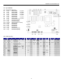
1
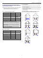
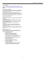
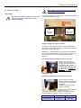
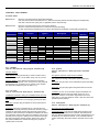
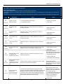
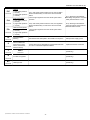
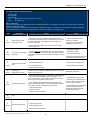
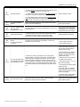
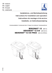
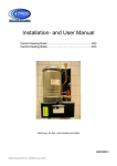
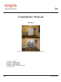
EN
Installation Manual
TWIN80C
Wall hung, fan flue, room sealed, high efficiency gas boiler
CHAPTER 1. GENERAL
CHAPTER 2. INSTALLATION
CHAPTER 3. COMMISSIONING
CHAPTER 4. FAULT FINDING
CHAPTER 5. PERIODICAL MAINTENANCE
CE-CERTIFICATE
2007
E000129016
installation manual TWIN 80 EN
CONTENTS
CHAPTER 1. GENERAL
1.1. Technical data……………………………………………………………………………………………………………… 04
1.2. Dimensional sketch…………………………………………………………………………………….………………….. 05
1.3. Boiler layout…………………………………………………………………………………………….…………………… 06
1.4. Diagrams
1.4.1. Functional flow diagram………………………………………………………………….……………………. 08
1.4.2. Wiring diagram…………………………………………………………………………..…………………….. 09
1.5. Condensing boiler………………………………………………………………………………………………………….. 10
1.6. Operation
1.6.1. Display
1.6.2. Master – Left hand side printed circuit board.
1.6.3. Slave –right hand side printed circuit board.
1.7. LED indication
1.8. Permitted flue discharge and air supply resistance………………………………………………………..…………… 11
1.8.1. “Concentric flue and air” system
1.8.2. “2 pipe” system
1.9. Configurations……………………………………………………………………………………………………………… 12
1.10. Regulations
CHAPTER 2. INSTALLATION
2.1. Mounting………………………………………………………………………………………………..……………………. 13
2.1.1. Bracket
2.1.2 Adapter
2.1.2.1. “Concentric flue and air” system
2.1.2.2. “2 pipe” system (100/100)
2.1.3. Boiler
2.2. GAS………………………………………………………………………………………………….………………………. 14
2.3. WATER
2.3.1. Safety valve
2.3.2. Filling and straining device
2.3.3. Expansion vessel……………………………………………………………………………………….………………… 15
2.3.4. Dirt filter
2.3.5. Differential bypass valve
2.3.6. Condensation discharge
2.4. PUMP………………………………………………………………………………………..………………………………. 16
2.4.1. Unit system pump
2.4.2. External system pump (option)
2.5. ELECTRICAL……………………………………………………………………………………………………………….. 17
2.5.1. Supply connection
2.5.2. Supply fuse
2.5.3. Input
2.5.4. Output
2.5.5. Cascade connection of master and slave
2.6. Lay-out BIC992………………………………………………………………………………….………………………….. 18
2.6.1. Connectors & pinning
2.6.2. Table, pinning
2.7. Green connector block……………………………………………………………………………………………….……. 19
2.7.1. 24 Volt on/off room thermostat (standard)
2.7.2. 0-10 Volt input regulation (standard)
2.7.3. OpenTherm (standard)
2.7.4. Outdoor sensor (standard)
2.8. Options with installer responsibility……………………………………………………………………………………….. 20
2.8.1.
2.8.2. 230 Volt room thermostat (installer responsibility)
2.8.3. Remote alarm (installer responsibility)
CHAPTER 3. COMMISSIONING
3.1. Filling…………………………………………………………………………………………………………..…………….. 21
3.2. Reading the water pressure
3.3. Venting
2
installation manual TWIN 80 EN
3.4. Chimney sweeper function
3.5. Gas/Air Ratio………………………………………………………………………………………………..……………….. 22
3.5.1. Pre-adjustment to be done in voltage-free condition:
3.5.2. Final Gas/Air adjustment (CO2 analysing)
3.6. Conversion to LPG…………………………………………………………………………………………………………. 23
3.7. MENU STRUCTURE……………………………………………………………………………………………………….. 24
3.7.1. Outdoor temperature sensor……………………………………………………………..…………………… 25
3.7.2. Domestic hot water (3-Way valve and cylinder to initiate by installer)
3.8. CASCADE……………………………………………………………………………………………………………..…….. 26
3.8.1. Power mode (default)
3.8.2. Comfort mode (field adjustable)
CHAPTER 4. FAULT FINDING
4.1 Boiler states…………………………………………………………………………………………………………………. 27
4.1.1. Standby
4.1.2. Pre rinse
4.1.3. Ignition
4.1.4. In operation
4.1.5. Post rinse
4.1.6. Pump after run
4.2. Status indications
4.2.1. Status indication during “operation mode”………………………………………………………………….. 29
4.2.2. Status indication during “blocking action”……………………………………………………….………….. 31
4.2.3. Status indication during ”lock-out”…………………………………………………………………………… 33
4.2.4. Chimney sweeper function (temporarily display for service purposes)…………………………..……… 35
CHAPTER 5. PERIODICAL MAINTENANCE
5.1. Checking the CO2 percentage……………………………………………………………………..……………..………. 36
5.2. Measuring the load of the unit
5.3. Cleaning the condensation water drain
5.4. Ionisation probe
5.5. Water pressure
CE-CERTIFICATE…………………………………………………………………………………………………………………….……. 37
3
installation manual TWIN 80 EN
CHAPTER 1. GENERAL
1.1. Technical data
Boiler type
Gas type
Electrical data
80C
natural gas G20
Supply / Frequency
LPG gas G30/G31
230 V / 50 Hz
(195 ÷ 270V @ 47,5 ÷ 52,5Hz)
Power consumption (max.)
280 W
Thermostat voltage
Dimensions and
weight
Emission value
24 Volt / OpenTherm / 0-10V
Height
950 mm
Width
710 mm
Depth
360 mm
Weight
65 kg
CO2
8.2% - 8.8%
9.2% - 9.8%
CO (0% 02)
12 –100 ppm
NOX (0% O2)
10 – 30 ppm
Flue gastemperature
at 80/60ºC
< 70ºC
at 50/30ºC
< 35ºC
Max. chimney
resistance
Connections
Air feed and flue tube together
125 Pa
Gas
G 3/4 ” outside
Heating (flow and return)
G 1 1/4” outside
Overflow
Air feed and flue
tube system
Boiler heat
exchanger
siphon
Concentric system
Ø 100 / 150 mm or Ø 110 / 150 mm
Water contents
4L
Max. temperature
90°C
Max. operating pressure
3.2 bar
Max. system pressure
Sound level
4 bar
Pump high
45 dB(A)
Pump low
Certification
35 dB(A)
CE Identification number
CE0063-AT3070
Cascade selection : menu parameter “.o” = 1
Gas type
Gas technical
data
TWIN in power mode
natural gas G20
Nominal gas pressure
LPG gas G30/G31
20 mbar
37/50 mbar
Heat input (gross)
16.2 – 82.2 kW
Heat input (net)
14.6 – 74.0 kW
Nominal output at 80/60ºC
14.1 – 72.0 kW
Nominal output at 50/30ºC
15.6 – 75.3 kW
Efficiency at 80/60ºC (net)
Low load = 96.6 %; High load = 97.2 %
Efficiency at 50/30ºC (net)
Low load = 106.9 %; High load = 101.8 %
4
installation manual TWIN 80 EN
1.2. Dimensional sketch
Dimensions in mm
Free space: There must be sufficient space at the top and bottom to be able to suspend the unit and to be able to connect all feed
and drain pipes. Normally, roughly 300 mm is required.
It is recommended to leave a free space of 150 mm on the left (for servicing reasons) and 50 mm on the right of the unit.
The front of the unit must be easily accessible for servicing at all times.
Connections
Pos 1 = Flow connection G1¼” male tread
Pos 2 = Return connection G1¼” male tread
Pos 3 = Gas connection G¾” male thread
Pos 1
Pos 2
Pos 3
5
installation manual TWIN 80 EN
1.3. Boiler layout
6
installation manual TWIN 80 EN
pos
01
02
03
04
05
06
07
08
09
10
11
12
13
14
15
16
17
18
19
20
21
22
23
24
25
26
27
28
29
30
31
32
33
34
35
36
37
38
39
40
41
42
43
44
45
46
47
48
49
50
51
52
53
54
55
56
57
58
59
60
description
Assembly frame
Cover
Flow collector
Return collector
Gas collector
Unit type 40
Burner type 40
Pump
Internal flow pipe
Kst. pump type 40
Internal return pipe
Kst. flow type 40
Sealing plug
Ionisation probe
Glow plug
Temperature sensor pipe
manager
Safety valve
plug
manual vent
Manifold exhaust
Nipple condensate tray
Sealing condensate tray
Sealing ring
Connection siphon
Connection nut
Tube of safety valve
Strain relief
Sealing ring
Sealing ring
Flue gas sensor
Cil.screw
screw
Green connection block
Strain relief
Nut for strain relief
Valve extension
Nipple male/male
plug
Fixation bracket
Pressure sensor
Filling/straining device
El. connection material
Cil.screw
Sealing flowpipe
Sealing ionisation probe
Sealing glow plug
Condensate tube
0-ring
Connection nut
Bracket manifold L.
Bracket manifold R.
Bracket flue pipe
Cil.screw
LED with wire
Nut for strain relief
Nut
sleeve
Sealing ring gas
Sealing ring
Beschreibung
omschrijving
Montagekasten
Mantel
Vorlauf-Versammelrohr
Rücklauf-Versammelrohr
Gas-Versammelrohr
Wärmetauscher Typ 40
Brenner Typ 40
Pumpe
Vorlaufrohr
Kst.Pumpe Typ 40
Rücklaufrohr
Kst.Vorlauf Typ 40
Dichtung
Ionisationssonde
Glühzünder
Temperatursensor
Brennerautomat
Sicherheitsventil
Dichtung
Handentlüfter
Kaminstück
Verbindungsstück
Dichtung Kondensatwanne
Dichtring
Siphonanschlussstück
Verbindungsmutter
sicherheitsventilschlauch
Ziehentlaster
Dichtring
Dichtring
Abgastemperaturfühler
Zilinderkopfschraube
schraube
Grüne Anschlussblock
Ziehentlaster
Ziehentlastermutter
Ventilverlängerung
Verbindungsnippel
Dichtung
Fixierungsbügel
Drucksensor
Fühl/Entlehrhahn
El. Verbindungsmaterial
Zilinderkopfschraube
Dichtung Vorlauf
Dichtung Ionisationssonde
Dichtung Glühzünder
Kondensatabfuhrschlauch
0-Ringe
Verbindungsmutter
Bügel Versammelrohr L.
Bügel Versammelrohr R
Bügel Abgasrohr
Zilinderkopfschraube
LED mit Schnur
Ziehentlastermutter
Mutter
Klemmring
Dichtungsring Gas
Dichtungsring
7
Achterwand
Voorkap
manifold aanvoer
manifold retour
Gas-manifold
Ketellichaam type 40
Brander type 40
pomp
Leiding aanvoer
Kst. pomp type 40
Leiding retour
Kst. aanvoer type 40
plug
ionisatiepen
gloeiontsteker
Aanlegvoeler buis
besturing
overstortventiel
plug
handontluchter
Broekstuk rookgasafvoer
Slangpilaar condensbak
Pakking condensbak
Doorvoerrubber condensb.
Aansluitbuis sifon
connectiemoer
overstortslang
kabelwartel
pakkingring
doorvoertule
Voeler rookgas
Cil.schroef met bzk
Zelfdraadv.schroef
Steker 6-polig
PG-wartel
Contramoer PG-wartel
kraanverlengstuk
Dubbele nippel
plug
Fix.beugel aanvoerleiding
Druksensor
Radiator aftapkraan
kabelbundelband
Cil.schroef met bzk
Afdichting aanvoerleiding
Pakking ionisatiepen
Pakking ontsteekpen
condensafvoerslang
0-ring
connectiemoer
Sluitplaat manifold L.
Sluitplaat manifold R.
Kapbeugel broekstuk
Cil.schroef met bzk
LED met kabel
Contramoer kabelwartel
knelmoer
knelring
Pakkingring gas
pakkingring
No.
Wilo RS15/7-2ku
Ø33,5
Beru
230 VAC
Ø 22
SIT master / slave
Emmeti 3,2 bar
G½”
G1½”
Ø19 x Ø13
22-32 M40
1”
Ø38 x Ø24,9
Tasseron
M6 x 12
M3 x 8
Onkenhout
Onkenhout
G¾” x G¾”
Ø12
Huba / IMIT
G½”
M6 x 60
Ø15,54 x Ø2,62
G¾”
M6 x 20
M40
G½” x 15
Ø15
G¾”
Ø25 x Ø21 x 1,5
1x
1x
1x
1x
1x
2x
2x
2x
2x
2x
2x
2x
1x
2x
2x
4x
1x
1x
1x
2x
1x
1x
2x
2x
1x
2x
1x
1x
8x
1x
2x
6x
12x
1x
1x
1x
1x
1x
6x
2x
2x
1x
25x
10x
4x
2x
2x
2x
4x
1x
1x
1x
1x
8x
2x
1x
2x
2x
2x
1x
installation manual TWIN 80 EN
1.4. Diagrams
1.4.1. Functional flow diagram
_t
Suppl y
X17-6
X17-3
_t
Ret ur n
X17-2
X17-5
X20-1
_t
Flue
X20
-2
X16-7
Running/Lockout
LED
X16-3
_t
O u ts ide
X16-6
X5-3
L1
X16-2
_t
DH W
Wat e r p r e ss u r e
se n s o r
X15-2
BIC-992
+
0 - 10 V
L1
X3-4
L2
X15-1
Threewayvalve
X15-3
X2-1
pe
X19-2
X2-5
L1
X2-4
L2
X2-3
L3
P u mp
2 30 Va c
X2-2
X19-1
24Vac
X3-5
X2-2
Wat e r p r e ss u r e
sw i tc h
BMS
pe
X5-1
X18-3
12Vdc
CH externe pump
X5-2
X18-1
PE
X2-1
X9-1
X8-2
Room therm.
X9-2
230Vac
X8-6
X1-3
Room therm.
X1-4
L1
V+
X8-5
Ha l l
X8-4
V-
Ven t i l a t o r
3 25 V dc
L2
X8-3
PE
X8-1
X11-1
OpenTherm
X11-2
X4-4
X10-2
G as v al v e
23 0 Vra c
RS - 4 8 5
X10-1
X4-3
230VAC
Saf e t y
230 Vac
X4-1
X22-1
X4-6
X4-5
L
N
PE
PE
ALARM
X22-2
X6-4
X7-4
X6-1
X7-2
X6-3
hsi
IO
X7-1
BURNER
RS 23 2S
8
installation manual TWIN 80 EN
1.4.2. Wiring diagram
9
installation manual TWIN 80 EN
1.5. Condensing boiler
give their heat to the system water. The flue gases are fed
outdoor, through the flue tube (F), into a combined flue tube
exhaust canal.
The formed condensation water (H2O) is discharged through the
waste trap.
The concentric air inlet and exhaust outlet need to be
connected with one of the adapter sets.
N00M990080
1.6.1. Display
The display operates for both printed circuit boards.
or
Open the door in front of the jacket for operating and reading the
codes on the display,
Concentric
100/150 mm
- The boiler of this picture is in the
stand-by mode, because the display
shows a continuous 0.
N00M990082
- The actual water temperature of
the flow sensor is 19‘C.
or
1.6.2. Master – Left hand side printed circuit board.
The Master is the leading board, calculates and divides the
necessary power over both units. Therefore the regulation
controls will always be connected to the Master.
•
Room thermostat 24 Volt
default
•
Outdoor temperature sensor
default
•
OpenTherm regulation
default
•
Room thermostat 230 Volt
optional
•
Direct control 0-10 Volt
optional
Concentric
110/150 mm
The TWIN 80C is a wall hung, fan flue, room sealed, high
efficiency condensing gas boiler for central heating and / or
under floor heating systems.
The type plate, which specifies the type of gas etc. to be used, for
which the unit is set, is on the left side of the unit.
Note: Spare part boards are set for SLAVE.
If needed, make SLAVE (A=1) into MASTER (A=0).
1.6. Operation
The appliance is equipped with pre-set gas/air ratio regulators.
The purpose of this regulator is to keep the gas/air ratio in the
burner as optimal as possible at all times e.g. when modulating.
This ensures clean and reliable combustion across the entire
load range. In addition it achieves high part-load efficiency.
1.6.3. Slave –right hand side printed circuit board.
In case of a lock-out of the Master printed circuit board the Slave
is still able to operate correctly.
1.7. LED indication
Two LED’s have been placed under the appliance informing the
user the status of each unit individually.
The TWIN 80C incorporates 2x type 40C heat units (existing of
2x heat exchanger, 2x premix burner, 2x fan, 2x gas valve, 2x
venturi, 2x circulation pump, 2x printed circuit board). Each heat
burner works independently, cascade controlled by two printed
circuit boards.
The left hand side LED (L) is indicating the actual status of the
Left hand side heating unit.
•
LED is ON = burner concerned is ON
•
LED is OFF = burner concerned is OFF
•
LED is FLASHING = unit concerned is LOCK-OUT
A fan sucks the air required for the combustion through the air
feed canal (A). Because the combustion air in the venturi sucks
an under pressure, the correct amount of gas (G) is
automatically added to the combustion air.
The flammable gas/air mixture thus obtained is fed to the
burner(s), via a mixing chamber, to be ignited at the surface of
the burner(s) by a ceramic glow plug. The hot combustion gases
are efficiently fed through the heat exchanger(s), where they
The right hand side LED (r) is indicating the actual status of the
right hand side heating unit.
•
LED is ON = burner concerned is ON
•
LED is OFF = burner concerned is OFF
•
LED is FLASHING = unit concerned is LOCK-OUT
10
installation manual TWIN 80 EN
1.9. Configurations
1.8. Permitted flue discharge and air supply resistance
The total resistance of the flue tube and air supply together
may not be greater than 125 Pa.
Preferably use flue tube materials, roof ducts and exterior wall
ducts with a quality mark.
For the use of plastic exhaust pipes both units are protected with
a flue gas temperature sensor.
In normal operation the application may produce a visible white
condensing “plume”.
Indication for the resistance values given in table below apply to
- Flue exhaust flow rate of max 122 m3/hour (at 70 ‘C)
3
- Supply air flow rate of max 96 m /hour (at 20 ‘C)
The TWIN is approved for application on the drain systems:
B23, C13(x), C33(x), C43(x), C53, C63(x), C83(x).
1.8.1. “Concentric flue and air” system
Concentric system
Ø 110/150 mm
Ø 100/150 mm
Type 80
Tube per metre
7.5 Pa
9.4 Pa
Bend 90°, R = 1.5 D
7.5 Pa
9.4 Pa
Bend 90°, R = 0.5 D
12.0 Pa
15.0 Pa
Bend 45°, R = 1.5 D
6.0 Pa
7.5 Pa
Bend 45°, R = 0.5 D
10.0 Pa
12.5 Pa
Roof duct 1.25 m
40.0 Pa
40.0 Pa
The concentric system 110/150 mm has been tested. The
test result show a maximum length of 10 meters
horizontally, including 1x bend of 90’ and a standard roof
duct.
Using the system 100/150 mm will reduce the maximum
length to 8 meters.
Please note each additional bend shortens the total
length with a meter in length.
1.8.2. “2 pipe” system
“2 pipe” system
Ø 110 mm
Ø 100 mm
Tube per metre
3,7 Pa
4.6 Pa
Bend 90°, R = 1.5 D
3.7 Pa
4.6 Pa
Bend 90°, R = 0.5 D
6.0 Pa
7.5 Pa
Bend 45°, R = 1.5 D
3.0 Pa
3.8 Pa
Bend 45°, R = 0.5 D
5.0 Pa
6.2 Pa
20.0 Pa
25.0 Pa
Type 80
Roof duct
11
installation manual TWIN 80 EN
1.10. Regulations
In case of non-compliance with the regulations, no
claims can be made against the guarantee conditions.
General safety regulations
The installation may only be performed by a recognised installer.
Take note that internal parts of the unit can carry a dangerous
electrical voltage (230 Volt).
Take note that the unit, the various pipes and the flue gas
exhausted by the unit can reach high temperatures (up to 90°C).
Before carrying out maintenance activities in or on the unit, you
must close the gas tap, switch off the electricity supply and pull
the mains plug out of the socket.
Environmental conditions
The area in which the unit is installed must satisfy the applicable
regulations.
The wall must be able to bear the weight of the unit (loaded
weight approx. 40 kg).
If you use a different assembly surface than a bricky wall of
sufficient thickness, you must select suitable fixtures yourself
and properly install the unit.
The unit may not be fitted in a chemically aggressive
environment.
The unit with air feed and flue gas exhaust satisfies the
requirements of protection class IP44 and may therefore be
installed in a wet area.
Although the unit is fitted with an internal frost protection, it may
not be exposed to extremely low ambient temperatures (lower
than -10°C).
Standards / Guidelines
With the installation of the unit, all local regulations must be
followed, where applicable, including the provisions of the
following standards and guidelines:
•
Building Regulations
•
Regulations for natural gas installations
•
Regulations for LPG (if applicable)
•
Guidelines for existing gas installations
•
Safety requirements for central heating installations
•
Safety provisions for low voltage installations
•
General regulations for drinking water installations
•
Water authority regulations
•
Ventilation in dwellings
•
Supply of combustion air and exhaust
•
House sewerage in homes and dwellings
•
Fire Brigade regulations
•
Factory Act regulations
•
Regulations applicable to HWS water Ask for the
locally applicable regulations at the local water
company as they are different in some areas
12
installation manual TWIN 80 EN
•
CHAPTER 2. INSTALLATION
2.1. Mounting
Before unpacking the unit, check whether the type of gas to be
used corresponds with the specification on the packing. If you
have any questions, contact your supplier.
•
To prevent back injury, take account of the fact that the weight of
the unit is roughly approx 65 kg. Care should be taken when
unpacking and mounting the appliance.
Fit either the Muelink & Grol adapter for the
connection of a concentric air intake and exhaust gas
outlet system of 100/150 mm or the Cox Geelen
adapter for the connection of a concentric air intake
and exhaust gas outlet system of 110/150 mm on top of
the boiler.
Fit later the concentric pipes onto the adapter
concerned.
2.1.2.2. “2 pipe” system (100/100)
Use the adapter 100/150 (Muelink & Grol) also for connection of
a “2 pipe” system (100/100) system and use the sealing ring
supplied to seal the air intake.
2.1.1. Bracket
To mount the appliance on a brick wall of sufficient thickness,
use the bracket supplied.
When the flue tube and air supply are connected eccentrically,
proceed as follows:
•
Fit the flue tube of diameter 100 mm in the opening, in
the adapter on top / left hand side of the boiler.
•
Fit the air supply of diameter 100 mm in the flange on
top / right hand side of the boiler.
2.1.3. Boiler
When you have determined the place of assembly, proceed as
follows:
• Draw the position of the bracket onto the wall.
• Use a masonry drill of 6 mm diameter to drill the holes with a
sufficient depth in the wall.
• Fit the plug’s in the drilled holes.
• Fix the bracket with the screw supplied.
To prevent back injury, take account of the fact that the
weight of the unit is roughly approx 65 kg. Care should be
taken when unpacking and mounting the appliance.
2.1.2 Adapter
2.1.2.1. “Concentric flue and air” system
Mount one of the adapter systems onto the boiler.
Adapter Muelink & Grol 100/150
(art. N00M990080)
Adapter Cox Geelen 110/150
(art. N00M990082)
•
•
•
13
Mount the appliance (TWIN boiler and adapter) onto the
bracket.
A-line the boiler horizontally.
Fix the position.
installation manual TWIN 80 EN
2.3. WATER
2.2. GAS
Both of the heat units are parallel jointed to central flow- and return water
collectors.
Make sure that the gas pipe work does not contain
dirt, particularly with new pipes.
Failure to install gas-appliances correctly could lead to accidents
and prosecution. It is in your own interest, and that of safety, to
ensure that the law is complied with.
WATER
G1¼” (male thread)
Connect the central heating flow pipe to pos 1 with G1¼” male
thread of the the collector on the far side.
Connect the central heating return pipe to to pos 2 with G1¼”
male thread of the collector on the nearr side.
G¾” (male thread)
•
•
•
•
•
•
The appliance has to be connected in accordance with the
current regulations.
Supply pipe works to be sized in accordance with relevant
regulations.
We advise a gas filter be fitted in the gas supply line in order
to prevent contamination of the gas valves.
Connect the gas pipe to the gas connection positioned under
the appliance in the middle. The appliance is equipped with
male gas thread G¾”.
Install the gas pipe stress free.
Include the gas pipe with an approved stopcock.
2.3.1. Safety valve
The boiler has been provided with a
safety valve of 3.2 bar.
The discharge under the boiler should
determinate facing downwards exterior to
the building in a position where
discharging water will not create danger
or nuisance but remains in a visible
position.
2.3.2. Filling and straining device
On the return collector of the boiler is a connection 1/2”
BSP female thread for the filling and straining device.
Install the filling and draining device,
packed with the boiler, onto this
connection in the central heating return
system. Do not use the safety valve as a
drain. The safety valve may not close
properly after passing contaminated
system water.
14
installation manual TWIN 80 EN
2.3.6. Condensation discharge
2.3.3. Expansion vessel
In the central heating return pipe, as near as to the boiler, an
expansion vessel must be fitted.
The size of the expansion vessel must
be determined on the basis of the central
heating water temperature and the total
water content the installation contains.
Mounting: The siphon (packed with the
boiler) fits onto the discharge pipe (Ø 32
mm) under the boiler. Tighten this
connection with the sealing ring and fix
the nut manually by hand.
The outlet of the siphon has to be
connected to the drain with a tundish.
Example of Emmeti “Expansion vessel”
The pre-pressure depends on the installation height above the
mounted expansion vessel.
5 meter - 0,5 bar
10 meter - 1,0 bar
15 meter - 1,5 bar
2.3.4. Dirt filter
If it may be expected that the central
heating water will be severely
contaminated by under floor heating,
fitting a 2 kg dirt fine filter in the return
pipe is recommended. With this, possible
contamination of the central heating
water is prevented from ending up in one
of the units.
Coopra cannot give any guarantee for
damage to the unit that is caused by dirt
in the system.
Example of PermaTrade “dirt filter” type PT-FM-25W
2.3.5. Differential bypass valve
A differential bypass valve must be installed on plants where it
may happen that various heating units (radiators) are
simultaneously excluded from the circuit because of the closure
of control or zone valves. It ensures a
recirculation proportional to the number
of shut off valves, thus avoiding noise
and keeping the pump pressure steady.
Example of Caleffi “Bypass valve”
type 519500 (¾”)
Mounting: The differential by-pass valve
must be mounted in the installation
between the flow and the return piping. It
may be mounted both horizontally and
vertically, provided that flow direction indicated by arrow is
respected.
Adjustment: Rotate knob on the desired value of the graduated
scale. The values correspond to the meters of pump head (m
H2O). The advised knob setting is 2.5-3.0. Lock the screw on the
groove knob.
15
installation manual TWIN 80 EN
2.4. PUMP
2.4.1. Unit system pump
The TWIN 80C is equipped with 2x Wilo, type RS 15/7 internal circulation pumps. Depending of the cascade selection and heat
demand one pump may run intermittent or both pumps may run simultaneously.
Use with a low velocity header (open header) can also be selected. In this case a larger secondary sided water output has to be
taken into account, in order to affect the height of the water temperature.
Fig.: Characteristic and the resistance graph of the application when
both unit pumps run.
2.4.2. External system pump (option)
If the capacity of the unit pumps is insufficient, an extra external system pump can be installed with the appliance.
The maximum absorbed current consumption of the external circulation pump may be 275 W (1,2 Amp).
On command of the printed circuit board, an external second system-pump will switch with the internal boiler-pump simultaneously.
Note the internal pump will switch high/low/off (2-stage) while the external pump will switch on/off (1-stage).
Earth
Neutral
Line
Earth
Neutral
Line
Terminal X5
printed circuit board
4 way Molex header 0 2” pitch
External system pump
230VAC
max 275W (1 2 Amp)
16
installation manual TWIN 80 EN
2.5. ELECTRICAL
2.5.1. Supply connection
If a stationary appliance is not provided with a supply cord
and a plug or with other means for disconnection from the
supply having a contact separation of at least 3 mm in all poles,
the instructions shall state that such means for disconnection
must be incorporated in the fixed wiring.
If a stationary appliance is provided with a supply cord and a
plug in the instructions shall state that the appliance must be
positioned so that the plug is accessible
2.5.3. Input
Temperature sensors: 5Vdc ± 5%, R25 = 12kΩ, ß = 3980
Water pressure sensor: 12Vdc ± 20%, Ri = 100kOhm
0÷10V : Ri = 20kOhm
Room thermostat: 24Vac (standard)
Room thermostat: 230Vac (option)
OpenTherm: available on main board
1kHz, Manchester encoding conform specification 2.0
RS-485 : cascade input, SIT protocol
Ionisation: detection 100Vac
There must be an electrical outlet with Earth connection
available at a maximum distance of 1 m from the unit.
The electricity connection (230 VAC) must consist of Line,
Neutral and Earth and a good Earth connection (requirement for
good ionisation operation of the appliance).
If the supply cord is damaged, it must be replaced by the
manufacturer or is service agent or similarly qualified person in
order to avoid a hazard.
If the display of the unit gives the status code ‘U’, this
means the Line and Neutral connections are reversed.
2.5.4. Output
Glow plug: single switched 230Vac
Gas valve: double switched 230Vac
Fan : 325Vdc
Pump: unit system pumps (2-stage speed operated)
In operation/lock-out LED: 10mA dc
External lock-out contact: potential free contact
External system pump 230VAC max. 275W (1,2 Amp)
External 3-way valve and HWS cilinder
2.5.2. Supply fuse
2.5.5. Cascade connection of master and slave
If Master fuse fails the Slave
printed circuit board cannot get
commands from the Master to
take over processing.
cascade
connection
between
the red
terminals
If Slave fuse fails the Master
printed circuit board wil operate
normally and can heat the
system with one single unit.
Bus protocol: RS-485 (TIA/EIA-485-A)
Polarity: phase depending
Wiring: 2 wires (A and B),
Twisted pair, no shield
Shut-off resistance: not needed
Galvanic isolation: not needed
Communication: 9600 Baud
Master and Slave: Connected to the same PE-Line
F1
Supply Fuse
3.15 AT
17
installation manual TWIN 80 EN
2.6. Lay-out BIC992
2.6.1. Connectors & pinning
X1
4-way
Molex header
0.2” pitch
X2
5-way
Molex header
0.2” pitch
X3
5-way
Molex header
0.2” pitch
X4
6-way
Molex header
0.2” pitch
X5
3-way
Molex header
0.2” pitch
X6
4-way
Molex Minifit
X7
4-way
Molex header
0.2” pitch
X8
6-way
Molex header
0.2” pitch
X9
2-way
Molex Minifit (white)
X10 2-way
Molex Minifit (red)
X11 2-way
Molex Minifit (blue)
X12 10-way
latch connector for display
X15 4-way
Molex Minifit
X16 8-way
Molex Minifit
X17 6-way
Molex Minifit
X18 4-way
Molex Minifit
X19 2-way
Molex Minifit
X20 2-way
Molex Minifit (black)
X22 2-way
Molex Minifit (black)
2.6.2. Table, pinning
1
X1
PE
X2
PE
X3
PE
2
N
N
N
3
L
4
Rth
5
6
L1,
pump
X4
PE
X5
PE
X6
HSI
N
pump2
N’,
L
ionisagas valve pump2 tion
L’,
HSI
gas valve
Max Th
Max Th,
24Vdc
X7
PE
N
L
X8
PE
X9
X10
X11
X15
24V RS-485 Open input
(B)
Therm
X16
X17 X18 X19 X20 X22
Ext. 0V +12v contac
tan
t
k
L1, fan Rth RS-485 Open 12V+ outdoo return Ext. 0÷10V Led contac
(A)
Therm
r
tan
1K
t
k
L2, fan
12V- flue
flow
VHall
return
V+
outsid
e
flue
7
8
18
flow
installation manual TWIN 80 EN
2.7. Green connector block
The external regulations are to be connected to the green connector block.
All connections are volt-free contacts. Therefore, do not connect any
voltage to this block!
1.
2.
3.
4.
Strip about 5 mm off the insulation of the wires of the connection
concerned.
Stick the stripped ends of the wires into connections of the connection
block involved.
Make sure that the wires do not make a short circuit.
Firmly tighten the screws in the connection block.
Master
print
Green connector block
contacts (1) - (2)
24Volt on/off room thermostat
or
0-10Volt input
room thermostat
(if no regulation is used - bridge wire)
OpenTherm
contacts (3) - (4)
outdoor sensor
contacts (5) - (6)
external cylinder
external outdoor temperature sensor
(NTC of 12 kOhm at at 25°C)
10 kOhm sensor
or
12 kOhm sensor
or
cylinder thermostat (on/off)
2.7.1. 24 Volt on/off room thermostat (standard)
2.7.3. OpenTherm (standard)
- When the room thermostat is closed (heat demand), the set
point (desired central heating flow temperature) rises at a rate
of 2°C per minute until the maximum permissible central
heating flow temperature is reached (21 minutes from minimum
25°C to 82°C).
- When the room thermostat is open (end of heat demand), the
set point (desired central heating flow temperature) falls at a
rate of 4°C per minute to the minimum central heating
temperature (10.5 minutes from 82°C to minimum 25°C).
- The desired central heating flow temperature (set point) is
indicated by the modulating OpenTherm room thermostat.
- With an outdoor temperature sensor, the measured outdoor
temperature is sent to the OpenTherm room thermostat, which
uses it to calculate the desired central heating flow
temperature.
•
•
•
•
Connect the 24 Volt room thermostat to the green
connector block on contacts (1) and (2)
On the master print check the connection of the
white terminal (default)
Connect the OpenTherm modulating room
thermostat to the green connector block on
contacts (1) and (2).
RE-PLUG the connector of the Master to the blue
terminal (Master).
2.7.4. Outdoor sensor (standard)
2.7.2. 0-10 Volt input regulation (standard)
- When an external outdoor temperature sensor (heating) is
connected, the sensor must be an NTC with a resistance of
12kOhm at 25°C
- The set point indicates whether there is a heat demand.
- The desired central heating flow temperature (set point) is
given by the 0-10 Volt input.
- The regulation is field adjustable in the menu either on
temperature (°C) or on boiler input (kW)
•
•
•
Connect the 0-10 Volt regulation to the green
connector block on contacts (1) and (2)
On the master print check the connection of the
white terminal (default)
19
Connect the outdoor sensor to the green
connector block on contacts (3) and (4).
installation manual TWIN 80 EN
2.8 Options with installer responsibility
2.8.2. 230 Volt room thermostat (installer responsibility)
2.8.1.
All Coopra printed circuit boards have a terminal for connection
of a line voltage 230 Volt room thermostat.
•
At present Coopra does not supply any connection
cable for this option.
Pinning TERMINAL X1
pin
X1
1
2
3
4
PE = Earth
N
230VAC
room
thermostat
L
5
2.8.3. Remote alarm (installer responsibility)
All Coopra printed circuit boards have a remote lock-out
contact. This contact is potential free. The power for an external
signal, lamp or siren, has to be from external.
•
At present Coopra does not supply any connection
cable for this option.
Pinning TERMINAL X22
20
pin
X22
1
2
contact
contact
installation manual TWIN 80 EN
3). Open the air bleed cocks of the radiators one at a time. Use
an air bleed key for this. As soon as water comes out of the air
bleed cock, shut the cock off again.
CHAPTER 3. COMMISSIONING
3.1. Filling
After venting of the system, the appliance and all pumps
must be connected to the mains and be switched ON.
If the unit is not yet filled with water, the display shows a flashing
‘P’ and the water pressure in bar.
3.4. Chimney sweeper function
The chimney sweeper function has priority over the central
heating and HWS regulation.
The operational water pressure of
the appliance is between 0.5 bar
en 3.0 bar.
A good system is with a pressure
of about 1.5 to 2 bar.
The chimney sweeper function is
activated by simultaneously
pressing the "+ and the – buttons"
of the display in for longer than 5
seconds.
Proceed as follows:
1). Fully open all radiator taps.
2). Connect the water supply tube
to the filling and draining device in
the central heating system.
3). Fill the water supply tube with water. Let the air in the water
supply tube escape; because you want to fill the system with
water instead air.
4). Connect the fully filled water supply tube to the water tap.
5). Open both water taps with caution and fill the system.
6). When the water pressure is sufficient (> 1.3 bar), the flashing
‘P’ disappears from the display.
7). Close, after filling, the filling tap and remove the water supply
tube.
The ionisation current can be
read in microamperes in the two right segments.
The capacity that is immediately released is the maximum
central heating capacity.
Press the "- button" to go to
low load.
3.2. Reading the water pressure
To read the water pressure
directly from the display press
and hold the “+” button 5
seconds.
Press the "+" button to
switch back to full load.
The unit switches back to normal
operation either automatically
after about 5 minutes or by
pressing "-" button.
3.3. Venting
After filling, the heating installation must be vented.
Follow also instructions from the installer of the system for the
venting of possible other elements of the heating installation,
such as under floor heating.
Proceed as follows:
1). Take care all pumps are OFF.
Otherwise the pump(s) may move the air
through the system constantly.
2). During the venting process you also
may put the appliance main switch in the
supply cable OFF.
21
installation manual TWIN 80 EN
3.5.2. Final Gas/Air adjustment (CO2 analysing)
The gas controls are set in the factory to the type of gas to be
used. This type of gas is stated on the packaging and on the
identification plate. To check the settings, you have to make a
flue gas analysis.
3.5. Gas/Air Ratio
Note that each unit has to be set according to the same
procedure individually.
Proceed as follows:
(1). Venturi-screw – Full load adjustment
Turn the venturi screw anti-clockwise to increase the CO2 value,
clockwise to decrease it.
(2). Gas control screw – Low load adjustment
Turn the screw anti-clockwise to decrease the CO2 value on low
load, clockwise to increase it.
(3). Cover screw
(L)
(r)
rubber plug
Left unit
rubber plug
right unit
Remove the rubber plug (L) or (r) from the flue tube concerned.
It is not necessary to set the units in a certain order. Fit the
measurement probe of a flue gas analyser (CO2 meter) in the
measurement opening of the flue tube canal concerned.
3.5.1. Pre-adjustment to be done in voltage-free condition:
LPG GAS – Turn venturi-screw clockwise 3
completely down on its seat.
Then turn the venturi-screw anti-clockwise 4 for
1/2 complete turns.
NATURAL GAS – Turn venturi-screw clockwise 3
completely down on its seat.
Then turn the venturi-screw anti-clockwise 4 for 3
complete turns.
Adjusting full load
Make sure there is sufficient heat dissipation through the
heating.
Activate the chimney sweeper function on full load.
Read the CO2 value on the
analyser. If the value does not
correspond with the value in the
"CO2 setting" table, carefully
adjust the venturi-screw (1). Turn
the venturi-screw anti-clockwise
to increase the CO2 value,
clockwise to decrease it.
PRE- ADJUSTMENT MEASUREMENT:
Distance between Venturi-screw (1) and the Top of the
venturi-stud to be about:
9 12 mm for natural gas G25
9 14 mm for natural gas G20
9 16 mm for LPG gas G31
Adjusting low load
Activate the chimney sweeper function on low load
With a callipers vernier the distance between venturi-screw (1)
and the Top of the venturi-stud (1) has to be measured to find
the rough setting of the venturi-screw for full load, and
depending of the used gas type.
The exact adjustment of the setting has to be made using the
CO2 analysing method as described below.
Read the CO2 value on the
analyser. If the value does not
correspond with the value in the
"CO2 setting" table, carefully
adjust the gas control adjusting
screw (2). To do this, temporarily
remove the cap (3) with the aid of
a Torx-screw driver. Turn the
screw anti-clockwise to decrease
the CO2 value on low load, clockwise to increase it.
22
CO2 setting
full load
low load
Natural gas
(G20, G25)
8,8 % CO2
8,2 % CO2
installation manual TWIN 80 EN
3.6. Conversion to LPG
First: Always screw the venturi adjusting screw
fully clockwise until it blocks.
High voltage!
Fit a flue gas analyser (CO2 meter) in the measurement opening
of the flue tube canal concerned.
The wiring of the pump, the three-way valve, fan
and wiring of the gas control can be under a
voltage of 230 VAC.
(L)
(r)
rubber plug
Left unit
rubber plug
right unit
Setting Full load on Propane as follows:
Unscrew the venturi adjusting screw 1/2 turns anti-clockwise.
(A guide for the dimension from the top of the screw to the top of
the support is given in the table).
Read the CO2 value on the flue gas analyser. If the value does
not correspond with the value for propane gas G31 (9,8% CO2),
carefully adjust the venturi-screw until the correct value is
obtained.
Activate the chimney sweeper function on full load.
Read the CO2 value on the
analyser. If the value does not
correspond with the value in the
"CO2 setting" table, carefully
adjust the venturi-screw (1). Turn
the venturi-screw anti-clockwise
to increase the CO2 value,
clockwise to decrease it.
Adjusting low load
Activate the chimney sweeper function on low load
If the gas control is already
properly adjusted for natural gas,
then the low load will not need to
be adjusted.
Activate the chimney sweeper
function on low load.
Check the CO2 value at minimum
capacity for propane gas G31of about 9.2% CO2.
If necessary, adjust the gas regulator screw until the correct
value is obtained. Note that this setting is a critical one.
23
CO2 setting
full load
low load
Propane (G31)
9,8 % CO2
9,2% CO2
installation manual TWIN 80 EN
3.7. MENU STRUCTURE
•
•
•
•
Enter menu structure by pressing the Set/Reset button for 5 - 10 seconds.
Change the parameter(left segment) by pressing the Set/Reset button once, shortly.
Change the range value (two right segments) by pressing the “+” button or the “–“ button.
To enter the view mode directly, press the “+” button for 5 – 10 seconds. The first upcoming reading is the system
water pressure (8).
User / Installer settings (TWIN 80C)
Parameter
Description
Range
C
O
P
Heating: Maximum flow temperature
Heating: Pump post-running time
Heating: Maximum boiler input
(percentage of maximum heating input of 74.0 kW)
25°C – 90°C
01-25 min, CO=24 hour
h
Extended adjustments (password h=18)
10 – 99
r
u
Factory setting return mode;
excluded are the settings under parameter “h”
(enter this parameter by pressing “+” button for 5 sec)
0-10V regulation
o
Cascade configuration
S
Pump mode
33 – 100%
View mode of Left hand side unit (reading
r
View mode of right hand side unit (reading)
82°C
05 min
00 (100%)
10
= Factory setting
= Customised setting
0 = Regulation on temperature (°C)
1 = Regulation on boiler input (kW)
01 = Power configuration (input 14,6 – 74.0 kW)
00 = Comfort configuration (input 7,3 – 74.0 kW)
00 = Software
= Always high
L
Factory
settings
0 (4)
01 (4)
00 (4)
= Always low
8 = Water pressure (in bar)
1 = Flow temperature (in °C)
2 = Return temperature (in °C)
3 = 0÷10V
4 = Outdoor temperature (in °C)
5 = TWIN flow temperature (in °C)
6 = Flue gas temperature (in °C)
7 = Flame signal (in μA DC)
9 = Last lock-out
A = Last blocking (internal coding)
8 = Water pressure (in bar)
1 = Flow temperature (in °C)
2 = Return temperature (in °C)
6 = Flue gas temperature (in °C)
7 = Flame signal (in μA DC)
9 = Last lock-out
A = Last blocking (internal coding)
Note: (4) does not return to factory settings
Extended adjustments
To open the extended adjustments below please change parameter h=10 into h=18
1 = Slave
A
Printed circuit board configuration
0 = Master
2 = Stand-alone
0 = TWIN
F/d
External HWS cylinder configuration
1 = Master only
0 = central heating unit
2 = for external HWS cylinder 12kOhm (suitable
H
Type of application
for large volume cylinders)
3 = for external HWS cylinder 10kOhm (suitable
for large volume cylinders)
Note: (4) does not return to factory settings
24
1 (4)
0 (4)
0 (4)
installation manual TWIN 80 EN
3.7.1. Outdoor temperature sensor
Outdoor sensor
An outdoor temperature sensor (heating) must be an NTC with a resistance of 12 kOhm at 25°C
(connected to terminals (3) and (4) of the green connector block)
ParaDescription
Range
meter
C
Maximum flow temperature
25°C – 90°C
O/b (3)
Base temperature (minimum flow temperarure)
10°C – 70°C
O/S (3)
Slope (flow temperature versus outdoor temperature)
01 – 100 (AO=100)
O/d (3)
Day reference temperature (set point flow temperature
at outdoor temperature of 20°C)
0°C – 70°C
Factory
settings
82°C
40°C (4)
20 (4)
40°C (4)
Note: (3) Active when an outside sensor is connected, Note: (4) does not return to factory settings
Adjusting flow temperature curve
Parameter C : This parameter will set the maximal heating
flow temperature (default 82°C).
O/b-value : This parameter will set the minimal flow
temperature (default 40°C).
O/S-value : This parameter will set the slope of the curve;
change of flow temperature depending on the outdoor
temperature (default 20 = 2:1).
O/d-value : This parameter will set a specific point; the flow
temperature (default 40°C).at an outdoor temperature of 20°C.
3.7.2. Domestic hot water (3-Way valve is not included and is and is to initiate by installer)
external HWS cilinder
Boiler extended by installer with an external 3-way valve and external HWS cilinder (range H=2 or H=3)
ParaDescription
Range
meter
b (2)
Set point exterrnal HWS cylinder
25°C - 70°C
F (2)
Fill temperature external HWS cylinder
65°C - 90°C
Note (2): Active when external HWS cylinder is connected; Note (4): does not return to factory settings
25
Factory
settings
60°C (4)
85°C (4)
installation manual TWIN 80 EN
3.8. CASCADE
3.8.1. Power mode (default)
•
•
3.8.2. Comfort mode (field adjustable)
•
•
Menu parameter “o” = 01 (default)
Both units run simultaneously.
When the room thermostat or space unit indicates that heat is
required for central or under floor heating, both units will heat
simultaneously. The Master print calculates the system flow
temperature and divides the necessary power over both units
equally. The speeds of both fans are automatically adapted to
the heat required, also with the use of an on/off thermostat.
Menu parameter “o” = 00
At low heat demand the units run independently.
When the room thermostat or space unit indicates that heat is
required a single unit will start-up, while the other unit remains
stand-by. The unit priority will change each 24 hours.
When the heat required is twice low fire, the second unit will be
started as well. Both units will heat simultaneously. The Master
print calculates the system flow temperature and divides the
necessary power over both units equally. The speeds of both
fans are automatically adapted to the heat required, also with
the use of an on/off thermostat.
When the room thermostat or space unit indicates that the
desired temperature has been reached, the central heating
water is no longer heated. The unit pumps will continue to run
for a previously set time to distribute the heat evenly over the
heating installation.
menu parameter “o” = 01
menu parameter “o” = 00
Heat input (gross)
16.2 – 82.2 kW
Heat input (gross)
8.1 – 82.2 kW
Heat input (net)
14.6 – 74.0 kW
Heat input (net)
7.3 – 74.0 kW
Nominal output at 80/60ºC
14.1 – 72.0 kW
Nominal output at 80/60ºC
7.0 – 72.0 kW
Nominal output at 50/30ºC
15.6 – 75.3 kW
Nominal output at 50/30ºC
7.8 – 75.3 kW
Efficiency at 80/60ºC (net)
Efficiency at 50/30ºC (net)
Low load = 96.6 %
Efficiency at 80/60ºC (net)
High load = 97.2 %
Low load = 106.9 %
Efficiency at 50/30ºC (net)
High load = 101.8 %
26
Low load = 96.0 %
High load = 97.2 %
Low load = 106.3 %
High load = 101.8 %
installation manual TWIN 80 EN
CHAPTER 4. FAULT FINDING
4.1 Boiler states
Burner is on
- when the room thermostat is closed (heat demand)
- and when the actual flow temperature is 5°C below the set point (desired central heating flow temperature)
- and after 3 minutes anti-cycling time, if applicable, after a reciprocal stop.
Burner is off
- when the room thermostat is open (end of heat demand)
- when the actual flow temperature is 3°C above the set point (blocking)
- or when the actual flow temperature is 3°C above the maximum permissible central heating temperature.
Standby
Pre rinse
Ignition
Heat operate
Post rinse
Pump
after run
Standby
heat demand
fan
gas valve
glow plug
ionisation
pump
t=0sec
t=3sec
t=7sec
t<12sec
4.1.1. Standby
(Fan off - Gas valve off - Glow plug off - Ionisation off)
4.1.3. Ignition
(Fan on - Gas valve on - Glow plug on/off - Ionisation
off/on)
No heat demand.
Heat demand: During the standby, a check is made to see if
there is heat demand. If so the boiler will go over to “pre rise”.
The ignition sequence of the burner is initiated.
Fan: The fan is running at the ignition speed (2900 rpm).
No heat demand: If the difference between flow and return
temperatures is larger than ± 5°C, once per hour, the pump will
be switched on for a maximum of 10 minutes to see whether
the temperature difference goes to within ± 5°C.
Gas valve: The gas valve coil is activated and opens the safety
valves.
Glow plug: The glow plug ignites the gas/air mixture from the
burner.
4.1.2. Pre rinse
(Fan on - Gas valve off - Glow plug on - Ionisation off)
Ionisation: As soon as an ionisation signal is measured, the
glow plug is switched off and the boiler will go over to “in
operation”. If there is no ionisation signal at the end of the
safety time, a new start attempt is made, if this was not the last
permitted (fourth) attempt.
Combustion chamber is being pre-ventilated with air from the
burner fan(s).
Fan: The fan is switched on at the purging speed (1350 rpm).
Glow plug: The glow plug is switched on at the same time as
the fan.
4.1.4. heat operate
(Fan on - Gas valve on - Glow plug off - Ionisation on)
Pump test: The pump is switched off for 3 seconds and the
water pressure (static pressure) is measured. Then the pump is
switched to high speed and the water pressure (active pump
pressure) is also measured. If the difference between the active
pump pressure and the static pressure is between 0.05 bar and
0.54 bar (0.64 for type 40 / TWIN) a correct water flow through
the heat exchanger is present and the “ignition time” starts. If
the pressure difference is outside this range, the pump test
repeats each 15 seconds.
The burner is on in heating mode.
Temperature test: To ensure the water flow through the heat
exchanger a temperature test is activated. After each burner
start, the difference between flow and return temperatures must
be raised by 3°C within 20 seconds. If not, the boiler makes a
restart. Eventually, after three restarts, the boiler runs into lockout.
27
installation manual TWIN 80 EN
Pump monitoring: When the temperature difference between
flow and return is greater than 30°C, the pump switches to a
high speed. When the temperature difference drops below 10°C
again, the pump switches back to a low speed. If the pump is
on for a HWS demand (combi-boiler or external cylinder), the
pump is continuously at high speed.
System water pressure monitoring: If the system water pressure
changes by more than ± 0.27 bar (and ± 0.3 bar with changing
pump speed) within 4 seconds, the regulation will block and
switch over to the pump test program. This test is defeated with
switching over from heating to hot water operation and reverse
for 16 seconds.
4.1.5. Post rinse
(Fan on - Gas valve off - Glow plug off - Ionisation off)
Combustion chamber is being post-ventilated with air following
boiler operation.
At end of heat demand (burner stop) the regulation runs into
post-rinse. The fan runs at the last demanded speed for 20
seconds.
4.1.6. Pump after run
(Fan off - Gas valve off - Glow plug off - Ionisation off)
The pump is mixing the heating water over the system.
The pump continues to run over the heating circuit for a certain
time period (adjustable, with minimum of 1 minute and
maximum of 24 hours).
28
installation manual TWIN 80 EN
4.2. Status indications
The left segment (A) indicates:
• status code or
• parameter value in menu mode
The two right segments (B) indicate:
• temperature or system water pressure or
• parameter value (in menu mode)
A dot on the status display indicates: The flame on burner is
present.
A = Status display
B = Reading
C = “+” button
D = “-“ button
E = Set/Reset
F = Flame present
4.2.1. Status indication during “normal operation mode”
During normal operation, the status display shows a continuous indication
Status
code
--
description
initialisation
action
repair
after restoration of supply power, pre-purging
- no heat demand, pump off, burner off
O
stand-by
continuous
c
continuous
h
continuous
Heating
- pump is in post-running mode, time-adjustable in menu
DHW combi-boiler and
HWS external cylinder
- end of heat demand
post-running, pump
on, burner off
heat demand, pump
on, burner off
blocked burner caused
by the 3 minutes anticycling timer
boiler not required to be on
- end of heat demand
post-running, pump
on, burner off
Heating
C
- once per hour, the difference between flow and return
temperatures must be less than 5°C. If this is not the case,
the pump will be switched on
- pump is in post-running mode, mixing the primary heat
exchanger and internal tank for ½ minute
- burner is in starting-up sequence
- burner starts within 10 seconds
- heat demand (heating), pump on, burner off
- however, burner is blocked caused by the anti-cycling
timer
burner starts after 3 minutes anticycling time
blocked burner caused
by maximum working
temperature blocking
(97°C)
If the flow sensor temperature or return sensor
temperature exceeds 97°C, the burner is switched off
block removes when the actual
flow temperature becomes 5°C
below the maximum working
temperature
blocked burner caused
by set point
temperature blocking
burner is off when the actual flow temperature is 3°C
above the set point (desired central heating flow
temperature may be between 25°C - 90°C)
block removes when the actual
flow temperature becomes 5°C
below the set point
blocked burner caused
by difference
temperature blocking
(flow / return difference
< –5°C)
If the temperature difference between flow and return
sensor becomes less than –5°C negative, the burner is
switched off
block removes when the
temperature difference between
flow and return sensor becomes
within –5°C
blocked burner caused
by difference
temperature blocking
(flow / return
temperature > 45°C)
If the temperature difference between flow sensor and
return sensor becomes greater than 45°C, the burner does
not fire-up
block removes when the
temperature difference between
flow and return sensor becomes
less than 20°C
blocked burner caused
by high glow plug
protection counter
- at each ignition the glow plug protection counter is
incremented. If the glow plug counter is too high, the boiler
start will be delayed
in time the glow plug protection
counter removes automatically
continuous
29
installation manual TWIN 80 EN
number
d
continuous
b
continuous
C.
continuous
d.
continuous
b.
continuous
DHW combi-boiler
heat demand, pump
on, burner off
HWS external cylinder
heat demand, pump
on, burner off
Heating
burner is on in heating
mode
DHW combi-boiler
burner is on in hot
water mode
HWS external cylinder
burner is on in hot
water mode
- glow plug protection counter is decremented 1 step per
minute
- burner is in starting-up sequence
- burner starts within 10 seconds
- burner is in starting-up sequence
- burner starts within 10 seconds
heat demand (heating), pump on, burner on, boiler is
operating
heat demand (internal tank), pump on, burner on, boiler is
operating
heat demand (external cylinder), pump on, burner on,
boiler is operating
Heating
P/C.
continuous
burner limited to low
load caused by low
water pressure (0.20.5 bar)
- heat demand (heating), pump on, boiler is operating
- however, with a system water pressure between 0.2 and
0.5 bar, the burner is limited to low load
DHW combi-boiler
P/d.
continuous
burner limited to low
load caused by low
water pressure (0.20.5 bar)
HWS external cylinder
P/b.
continuous
burner limited to low
load caused by low
water pressure (0.20.5 bar)
- heat demand (internal tank), pump on, boiler is operating
- however, with a system water pressure between 0.2 and
0.5 bar, the burner is limited to low load
fill the system with water to a
water pressure of 1.5 - 2.0 bar
- heat demand (external cylinder), pump on, boiler is
operating
- however, with a system water pressure between 0.2 and
0.5 bar, the burner is limited to low load
Heating
A/C.
continuous
burner limited to low
load caused by high
flue gas temperature
(> 90°C)
- heat demand (heating), pump on, boiler is operating
- however, with a flue gas temperature above 90°C, the
burner is limited to low load.
DHW combi-boiler
A/d.
continuous
burner limited to low
load caused by high
flue gas temperature
(> 90°C)
HWS external cylinder
A/b.
continuous
o
continuous
o.
continuous
burner limited to low
load caused by high
flue gas temperature
(> 90°C)
burner action restores
automatically when the actual flue
gas temperature descends 80°C
- heat demand (internal tank), pump on, boiler is operating
- however, with a flue gas temperature above 90°C, the
burner is limited to low load
- check flue gas sensor
- check the water flow
- heat demand (external cylinder), pump on, boiler is
operating
- check primary heat exchanger
- however, with a flue gas temperature above 90°C, the
burner is limited to low load
frost protection 8°C
(heating), pump on,
burner off
If the flow sensor temperature is below 8°C, the regulation
starts the pump
frost protection 3°C
(heating), pump on,
burner on
If the flow temperature goes below 3 °C, the regulation
starts the burner to low load
(E000129016 - installation manual TWIN 80 EN - 030106v07
30
frost protection is finished, when
the temperature of the return
sensor is above 15°C
installation manual TWIN 80 EN
4.2.2. Status indication during “blocking action”
What is a blocking action?
The regulation blocks the burner till conditions are within certain requirements.
During blocking operation, the display status shows a continuous indication. Each blocking action will stay during the 3 minutes anticycling time.
Most blocking actions restore automatically. However, some need to be repaired or can be restored by interrupting the supply power.
Status
code
U
continuous
1
continuous
1.
continuous
2
continuous
2.
continuous
4
continuous
A
continuous
description
action
repair
supply Line and
Neutral reversed
- Line and Neutral are exchanged
- reverse Line / Neutral
- no good Earth present
- check wiring
flow sensor open
circuit
broken flow sensor, or wiring interrupted, or wiring not
correctly connected.
- replace flow sensor
- check wiring
flow sensor short
circuit
faulty flow sensor, or wiring interrupted, or wiring not
correctly connected
- replace flow sensor
- check wiring
return sensor open
circuit
broken return sensor, or wiring interrupted, or wiring not
correctly connected
- replace return sensor
- check wiring
return sensor short
circuit
faulty return sensor, or wiring short circuit or contact to
earth
- replace return sensor
- check wiring
flue gas sensor open
circuit
boiler will work without having a flue gas sensor as well,
unplug the sensor, and interrupt the supply power
- replace flue gas sensor
- check wiring
blocked burner caused
by high flue gas
temperature (>100°C)
burner action restores
automatically when the actual flue
gas temperature descends 80°C
If the flue gas sensor exceeds a temperature of 100°C,
the burner is blocked
- check flue gas sensor
- check the water flow
- check primary heat exchanger
H
continuous
P
continuous
blocked burner caused
by high flow
temperature (>105°C),
while the burner was
off
pump test at each
burner start
(pump test repeats
each 15 seconds)
If the flow sensor exceeds a temperature of 105°C, while
the burner is off, the burner is blocked
burner action restores
automatically when the actual flow
temperature becomes 5°C below
the set point
- at each burner start the boiler is doing a pump test
program. The boiler is starting and stopping the pump and
measuring the actual pressure sensor water pressures
pump test ends when a test
pressure difference is obtained
between 0.05 and 0.54 bar (0.64
bar for boiler type 40)
- the burner does not start when the difference between
the active pump pressure and the static pressure is less
than 0.05 bar or more than 0.54 bar (0.64)
- no water flow (system water flow
may be blocked by thermostatic
valves or zone regulation)
- check pressure sensor
- check pump
(E000129016 - installation manual TWIN 80 EN - 030106v07
31
installation manual TWIN 80 EN
P/C
continuous
P/d
continuous
P/b
continuous
nc
continuous
Heating
1). low water-pressure
(< 0.2 bar)
2). high water pressure
(> 3.0 bar)
DHW combi-boiler
1). low water-pressure
(< 0.2 bar)
2). high water pressure
(> 3.0 bar)
HWS external cylinder
1). low water-pressure
(< 0.2 bar)
2). high water pressure
(> 3.0 bar)
internal software
blocking
Ad 1). with water pressure below 0.2 bar, the regulation
blocks with alternately a continuous P and the normal
status.
The two right segments show the actual system water
pressure.
Ad 1). blocking mode releases
after filling the system to a system
water pressure above 1.3 bar
Ad 2). with water pressure above 3.0 bar, the regulation
blocks with alternately a continuous P and the normal
status.
Ad 2). blocking mode releases
when the system water pressure
descends below 2.9 bar
The two right segments show the actual system water
pressure.
the software was interrupted in the middle of a sequence
interrupt 230V supply power
sensor with incorrect temperature measurement between
97-115°C. The actual temperature differs.
replace the sensor concerned
sensor malfunction
9
continuous
(flow sensor, return
sensor, tank sensor,
outdoor sensor)
J
see C
continuous
continuous
E
(TWIN only)
no slave recognised
(TWIN only)
HWS right unit
(TWIN only)
continuous
b/r
continuous
(E000129016 - installation manual TWIN 80 EN - 030106v07
32
installation manual TWIN 80 EN
4.2.3. Status indication during ”lock-out”
- gas valve off
- glow plug off
- ionisation off
- fan
off (some lock-outs, post rinse for 1 minute)
- pump
on (max 24 hr)
What is a lock-out?
During lock-out operation, the display status shows a flashing indication. The regulation may lock-out for safety reason or after four
consecutive failed start attempts.
Most lock-out operations can be restored by pressing the ‘Set/Reset’ button. It is advised not to ask installer for help after using this
button several times in a row. Some lock-out operations need an interruption of the supply power.
Status
code
1
flashing
description
boiler does not pass
temperature test
action
- after burner start, the temperature difference between
flow sensor and return sensor must be raised by 3°C within
the first 20 seconds. If the difference is not made, the
burner is restarted.
- after three restarts, within one heat demand, the boiler
runs into lock-out.
repair
- check both flow and return
sensors for function
- check flow of system water
(blockage in pump area)
- check flame stability
2
flashing
3
flashing
too many re-start during
operation
internal communication
error
- If during operation the ionisation fails, the gas valve shuts
off immediately and a restart is made. If this failure causes
a third restart within the burner demand, the boiler runs into
lock-out
- check flame signal
- internal regulation fault
- interrupt 230 V supply power
- A/D conversion fault
- replace printed circuit board
- check ionisation wiring
- blocked condensation discharge
(condensate try full with water)
- external component fault
4
flashing
5
low flue gas
temperature (–25°C)
fan speed malfunction
flashing
f the flue sensor measures a temperature below –25°C, the
boiler runs into lock-out
check flue gas sensor
- If the measured fan speed, in operation, deviates from the
desired fan speed, the burner will be switched off, and
post-purge will start. If this blocking action lasts for more
than 1 minute, the boiler runs into lock-out
- check the fan for functioning
- If the measured fan speed exceeds the maximum fan
speed, the regulation blocks. If this blocking action lasts for
more than 1 minute, the boiler runs into lock-out
- communication fault
- broken fan motor
- printed circuit board failure
6
N/A
flashing
7
flashing
gas valve malfunction
- communication fault
- broken gas valve coils
- printed circuit board failure
(E000129016 - installation manual TWIN 80 EN - 030106v07
33
- check the fan coil resistance on
the two outermost terminals (R =
115 Ohm at room temp)
- check if the printed circuit board
powers 230 VAC on the two
outermost contacts of the fan
connector during start
installation manual TWIN 80 EN
- If during standby a false flame signal is detected for more
than 5 seconds, the boiler runs into lock-out
8
false flame signal
flashing
- If a false flame signal is detected with closed gas valve for
more than 5 seconds, the boiler runs into lock-out
check ionisation system
- If a false flame signal is detected during pre-rinse / postrinse, the regulation blocks. If the false flame signal lasts
for more than 5 seconds, the boiler runs into lock-out
9
flashing
A
flashing
E
successful software
update
after successful programming of the printed circuit board
status code shows flashing 9
press set/reset button
lock-out, caused by high
flue gas sensor
temperature (> 105°C)
If the flue gas sensor exceeds a temperature of 105°C, the
burner locks-out
why is the flue gas temperature
exceeding 105°C? The burner
was already on low load at 90°C
and blocked at 100°C, was it?
- software problem (to be restored by supply interruption)
internal interlock fault
flashing
H
flashing
lock-out, caused by
limiter,
high flow temperature
(> 105°C)
- hardware problem (cannot be restored by supply
interruption) is mostly a broken printed circuit board.
replace printed circuit board
- check flow sensor
If the flow sensor exceeds a temperature of 105°C, the
regulation runs into lock-out
- check system water flow
- check pressure sensor
- no voltage supplied from printed
circuit board (210 Vdc) to gas
control coils (broken board or
supply power too low).
F
flashing
too many start attempts
successively (four failed
start attempts in a row)
-at each burner start, while the fan runs at the ignition
speed (2700 rpm), the gas valve opens and a flammable
gas/air mixture is supplied to the burner. The glow plug
ignites the gas/air mixture at the surface of the burner. If
there is insufficient ionisation current measured at the end
of the safety time, a new start attempt will be made. After
four failed consecutive start attempts, the regulation locksout.
- gas inlet pressure too high, so
the gas control valves remain
closed on its seats (max. inlet
pressure 60 mbar).
- defective gas control coils (R =
4.1 kOhm at room temp).
- check glow plug (R = 1.0 – 1.4
kOhm at room temp).
- incorrect burner ignition (adjust
gas/air mixture).
- ionisation probe or ionisation
cable makes short circuit with
earth (correct ionisation current 6
to 13 micro Amps).
- ionisation probe with insulation
layer (clean with sandpaper)
O
flashing
open gas valve circuit
open circuit of the gas valve cable connector bridge,
terminal X4 of the printed circuit board
(E000129016 - installation manual TWIN 80 EN - 030106v07
34
repair short circuit bridge of gas
valve cable connector
installation manual TWIN 80 EN
4.2.4. Chimney sweeper function (temporarily display for service purposes)
Chimney function has priority over the heating functions
Status
code
C
FLASHING
description
chimney sweeper
function
action
- flashing left segment
= high load
- flashing left segment
= low load
The two flashing right segments show the ionisation current
in microamperes
(E000129016 - installation manual TWIN 80 EN - 030106v07
35
repair
- chimney sweeper function
removes after 10 minutes
automatically
- chimney sweeper function
removes manually by pressing
set/reset button
installation manual TWIN 80 EN
CHAPTER 5. PERIODICAL MAINTENANCE
5.4. Ionisation probe
High voltage!
When the unit burns on chimney
sweeper function, the ionisation
current can be read directly on
the display.
The wiring of the pump, the three-way valve, fan
and wiring of the gas control can be under a
voltage of 230 VAC.
Correct ionisation current
Full load: 6 µA DC to 13 µA DC
Low load: 3 µA DC to 13 µA DC
After the first year, have a certified installer or maintenance
man inspect the appliance. He can ascertain the maintenance
deadline on the basis of the inspection and circumstances.
The ionisation probe is a part
that wears. An insulating layer
can be formed in the flame at
high temperature. This layer can
be removed with fine sandpaper.
5.1. Checking the CO2 percentage
The nominal value for natural
gas at full load is 8.8% CO2.
The unit does not need to be
cleaned if the measured CO2
percentage at full load is within
8.8% CO2 and 9.4% CO2.
5.5. Water pressure
It is possible to read the water
pressure directly from the
display. To do this, press the "+"
button 5-10 seconds.
5.2. Measuring the load of the unit
A load drop can be the consequence of a clogged flue gas
channel or a clogged air intake channel. Check whether this is
the case by measuring the load on the unit. First set the central
heating capacity "P" to 100% in the menu. Let on the unit burn
on chimney sweeper function at full load. Measure the gas
consumption. If the ascertained
deviation in load is no more than
15% of the nominal value, the
flue gases can be sufficiently
exhausted and there is no
clogging. At the end of the
check, reset the central heating
capacity "P" in the menu to its
customer-specific value.
Check the water pressure; top up
and de-aerate as necessary.
Press the ‘plus’ button in for at
least 5 seconds to see the actual water pressure in bar on the
display.
Press briefly on the ‘min’ button to return to operational mode.
5.3. Cleaning the condensation water drain
There is an opening for this
purpose on the top of the vapour
tray. First remove the rubber
sealing plug; rinse the vapour
tray and drain with clean tap
water. When no more impurities
are removed, the vapour tray is
clean. Also clean the trap.
(E000129016 - installation manual TWIN 80 EN - 030106v07
36
installation manual TWIN 80 EN
(E000129016 - installation manual TWIN 80 EN - 030106v07
37
installation manual TWIN 80 EN
(E000129016 - installation manual TWIN 80 EN - 030106v07
38
installation manual TWIN 80 EN
(E000129016 - installation manual TWIN 80 EN - 030106v07
39
installation manual TWIN 80 EN
2007 Coopra Advanced Heating Technologies b.v.
All rights reserved.
Nothing from this document may be duplicated and/or made public by means of printing, photocopy, microfilm or in
any other way without prior written permission from the manufacturer. This also applies to the appropriate drawings
and/or diagrams.
The information supplied in this document is based on general data with regard to constructions, material
characteristics and working methods known at the time of going to print. Therefore, we reserve the right to make
changes without notification. For this reason, the instructions given serve only as a guideline for the installation, use
and maintenance of the unit shown on the cover of this document.
This document is valid for the unit in its standard version. Therefore, the manufacturer cannot be held liable for any
damage arising from specifications that deviate from the standard version of the unit delivered to you.
This document has been compiled with all possible care. However, the manufacturer cannot be held liable for any
mistakes in this document or for any consequences.
Take the time to read this document carefully before installing or using the unit. Always keep this
document near the unit.
COOPRA Advanced Heating Technologies b.v.
Vierlinghstraat 14
NL 3316 EL Dordrecht
Tel: +31 (0) 78 – 653 08 30
Fax: +31 (0) 78 – 653 08 33
40