1
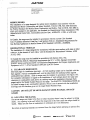
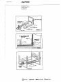
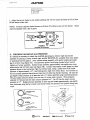
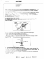
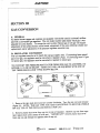
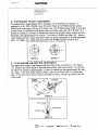
240Edwards
Street.SE
C]eveiand.
Tennessee
_7211
Tel:423-,-t72-3333
Fax:423-473-6710
GAS
INSTALLATION
MANUAL
SEALED TOP BURNERS
30" WIDE SELF-CLEAN
FREESTANDING
INSTALLER:
AND SLIDE-IN-RANGES
LEAVE THESE INSTRUCTIONS
WITH THE APPLIANCE.
PLFASE KEEP THIS MANUAL FOR FUTURE REFERENCE.
This manual is intended to assist in the initial installation and adjustments of the range.
YOUR RANGE MAY NOT BE EQUIPPED WITH SOME OF THE FEATURES
REFERRED TO IN THIS MANUAL.
SPECIAL WARNING
ONLY QUALIFIED PERSONNEL SHOULD INSTALL OR SERVICE THIS RANGE.
READ SAFETY INSTRUCTIONS IN USE AND CARE BOOK BEFORE USING THE
RANGE.
J_
.MAYI'AG
Ac_rnir_t Yl
*--r-_. a_._N-,t_dl=
"_iacji<:
C.",et
240E(;war_s
Street,SE
C',eveiand,
Tannessee
37311
Tel:423-472-_333
Fax:
_23-._78-_71D
SECTION
1
INSTALLATION
A. SERVICE - PARTS INFO1LMATION
WHEN YOUR RANGE REQUIRES SERVICE OR REPLACEMENT PARTS, CONTACT YOUR DEALER OR AUTHORIZED SERVICE AGENCY. PLEASE GIVE
THE COMPLETE MODEL AND SERIAL NUMBERS OF THE RANGE WHICH IS
LOCATED ON THE RANGE MODEL NUMBER PLATE. NOTE: THE RANGE
MODEL NUMBER PLATE IS LOCATED ON THE LOWER FRONT FRAME OF
THE RANGE.
B. CODES.
These units must be installed to conform with all local codes, rules and regulations including
municipal, provincial and state building codes, as well as local utility regulations. Ranges
approved for Canada will have the Canadian Gas Association (CGA) approval seal on the
model number plate. Ranges approved for Canada have been tested to insure compliance
with CGA 1.1.
ELECTR/C SUPPLY
The range must be installed in accordance with Local and National Electric Code (NEC)
ANSI/NFPA No. 70-1987.
In Canada the range must be installed in accordance with the current CSA Standard C22.1Canadian Electrical Code Part 1.
GAS SUPPLY
Installation of this range must conform with local codes or, in the absence of local codes,
with the National Fuel Gas Code, ANSIZ223.1-1988.
In Canada the range must be installed in accordance with the current CGA Standard
CAN/CGA-B149-Installation Codes tbr Gas Burning Appliances and Equipment and/or local
codes.
Check the range model number plate to see if the range is approved for installation in mobile
homes and/or recreational vehicles. If approved the following items are applicable.
Customer
Ser',rica
__
248Edwards
Street,SE
C]e,:e]and.
Tennessae
37311
Te;::;23-472-,3.333
Fax:423-478-67;0
MOBILE HOMES
The installation of a range designed for mobile home installation must conform with the
Manufactured Home Construction and Safety Standard, Title 24 CFR, Part 3280 (formerly
the Federal Standard for Mobile Home Construction and Safety, Tide 24 HUD, Part 280) or,
when such standard is not applicable, the Standard for Manufactured Home Installations 1982
(Manufactured Home Sites, Communities and Set-Ups), ANSIA225. i-t984, or with local
codes.
In Canada, the range must be installed in accordance with the current CSA Standard
C22.1-Canadian Electrical Code Part 1 and Section Z240.4.1-Installation Requirements for
Gas Burning Appliances in Mobile Homes (CSA Standard CAN/CSA -Z240MH).
RECREATIONAL VEHICLES
The installation of a range designed for recreational vehicles must conform with state or other
codes or, in the absence of such codes, with the Standard for Recreational Vehicles, ANSI
A119.2-1982.
In Canada the range must he installed in accordance with Section C22.2 No.
148/CAN/CSA-Z240.6.2-Electrical
Requirements for R.V. 's (CSA Standard CAN/CSEZ240RV Series) and Section Z240.4.2-Installation Requirements for Propane Appliances and
Equipment in R.V.'s (CSA Standard CAN/CSA-Z240 RV Series.
C. CLEARANCE DIMENSIONS
(See back page for installation drawings). All free-standing ranges can be installed with the
back against a vertical combustible wail, and the sides below the cooking surface against
combustible base cabinets. Slide-in ranges must be installed in accordance with figure 10C.
For complete information in regard to the installation of wail cabinets above the range and
clearances to combustible wails above the cooking top see the installation drawings (back
pages) and/or the Model Number Plate on the range. For SAFETY CONSIDERATIONS do
not install a'range in any combustible cabinetry which is not in accord with the installation
drawings and the clearance given on the range Model Number Plate.
CAUTION:
GUARD.
DO NOT LIFT OR MOVE RANGE BY DOOR HANDLES,
OR BACK-
D. LOCATING THE RANGE.
Do not set range over holes in the floor or other locations where it may be subject to strong
drafts. Any opening in the wall behind the range and in the floor under the range should be
sealed. Make sure the flow of combustion or ventilation air is not obstructed.
Be certain all packing materials are removed from the range before operating to prevent fire
tt_._I,A"tTAG
_l_mll'al
71
_,.,ilEi_lN.,i'tlll
"_"iafk:
e,"tt
240 EdwardsStreet,SE
CEeveiand,
Tennessee37311
Tet: 423472-3333
Fax::t23-478-67;O
or smoke damage should the packing material ignite.
NOTE: A range should NOT be installed directly over kitchen carpeting unless an insnladng
pad or I/4" thick piece of plywood is placed between the range and carpet.
COPIES OF THE STANDARD LISTED ABOVE MAY BE OBTAINED FROM:
NATIONAL FIRE PROTECTION ASSOCIATION
Batterymarch Park
Quincy, MA 02259
COPIES OF THE STANDARD LISTED ABOVE MAY BE OBTAINED FROM:
AMERICAN GAS ASSOCIATION
1515 Wilson Boulevard
Arlington, VA 22209
E. ANTI-TIP DEVICE INSTALLATION
INSTRUCTIONS
NOTE: A risk of rant tip over exist if the appliance is not installed in accordance with the
installation instructions provided. The proper use of this device minimizes the risk of TIPOVER. In using this device the consumer must still observe the safety precautions as stated
in the USE AND CARE MANUAL and avoid using the oven door and/or lower drawer as a
step stool.
Installation instructions are provided for wood and cement in either floor or wall. Any other
type of constructions may require special installation techniques as deemed necessary to provide adequate fastening of the ANTI-TIP bracket to the floor or wall.
Step 1 - Locating the Bracket
A, Mark the floor or wall where either the right or left "EDGE" of the 30" opening is to be
located.
B. Place the BRACKET SIDE, see figure 1, at the marked "EDGE" and against the back
wall.
C. Use the bracket as a template and mark the required holes, as shown in figure 1, for the
type of construction you will be using.
Step 2 - Anti-Tip Bracket Installation
A. Wood Construction:
1. Floor: Located the center of the two holes identified in figure 1 as "FLOOR-WOOD'.
Drill a 1/8" pilot hole in the center of each hole (a nail or awl may be used if a drill is not
_'_l ,MA_]'AG
Admiral
7|
zaui,_,JE N N -A_I:_
"i:_._a_j
J¢ C,_.¢f
_ustomerService
..__
240_c.wards
Street.SE
CleveJand.
Tennessee
3731
Tei:a22-_.72-3333
Fax:a23-478-_0
available). Secure the ANTI-TIP bracket to the floor with the two screws provided. Proceed
to Step 3.
2. Wall: Locate the center of the two holes identified in figure I as "WALL-PLATE'.
Drill an angled 1/8" pilot hole in the center of each hole as shown in figure 2. (A nail or awl
may be used if a drill is not available). Secure the ANTI-TIP bracket to the wail with the
two screws provided as shown in figure 2. Proceed to STEP 3.
B. Cement or Concrete Construction:
i. Suitable screws for concrete construction can be obtained at the hardware store. Drill the
required size hole for the hardware obtained into the concrete at the center of the holes identiffed in figure 1 as "FLOOR-CEMENT".
Secure the ANTI-TIP bracket to the floor.
Proceed to STEP 3.
Step 3 - Range Installation
A. Complete the installation of the range per the installation instructions provided with the
product.
B. Align the range to its designated location and slide it back into position. Note: A minimum clearance of 1/4" is required between the range and the leveling foot that will engage
the ANTI-TIP bracket, see figure 2.
C. For SAFETY CONSIDERATIONS as well as optimum performance adjust the range so
that it is level. This may be checked by placing a spirit level or a large pan of water on the
cooktop or the oven rack. If an adjustment is required pull the range forward, tip the range
and rotate the leveling feet as required.
D. To check the range for proper installation of the anti-tip bracket: Use a flashlight and
look underneath the bottom of the range to see that one of the rear leveling legs is engaged in
the bracket slot.
E. Proceed with the remainder of the instailation instructions provided with the range.
248 EdwardsStreet,SE
Cleveland,Tennessee37,311
Tel: 423-J72-3333
Fax:_t23-478-BTtO
GUn-E
•
1/4 N M_
F
.
/
PLATE
,_, ,=,,-7,, F]GURE2
, 11];
._.'_TA6
Admiral71
_E._N-_
_aejic
C.._et
Cu,_0mer
_r_ice
A0t][A'_.r_/_G
2aOEdwards
Street,SE
C1evelanar
Tennessee
,37311
Tei:423-472-3323
Fax:423-478-571
[3
F. CONNECTING THE RANGE
1. ELECTRICAL SUPPLY CONNECTION: The range requires 120 volts, 60 cycle
alternating current from an outlet capable of supplying I5 amperes.
WARNING: ELECTRICAL GROUNDING INSTRUCTIONS.
This appliance is
equipped with a three-prong grounding plug for your protection against shock hazard and
should be plugged directly into a properly grounded receptacle. Do not cut or remove the
grounding prong from this plug
WARNING: DISCONNECT ELECTRICAL SUPPLY BEFORE SERVICING THE
APPLIANCE.
2. GAS SUPPLY CONNECTION: A TRAINED SERVICEMAN MUST MAKE THE
GAS INSTALLATION.
a. A GAS CUTOFF VALVE SHOULD BE PUT IN AN ACCESSIBLE LOCATION IN
THE SUPPLY LINE AHEAD OF THE RANGE, FOR TURNING ON AND TURNING
OFF GAS SUPPLY. If range is to be connected to house piping with flexible or semirigid
metal connectors for gas appliances, CONNECTOR NUTS MUST NOT BE CONNECTED
DIRECTLY TO PIPE THREADS. THE CONNECTOR MUST BE INSTALLED WITH
ADAPTORS PROVIDED WITH THE CONNECTOR.
b. The house piping and/or range connector used to connect the range to the main gas supply
must be CLEAN, free of metal shavings, rut, dirt, and liquids (oil or water). Dirt, etc. in
the supply lines can work its way into the range manifold and in turn cause failure of the gas
valves or controls and clog burners and/or pilot orifices.
NOTE:
THE MAIN TOP DOES NOT LIFT UP.
c. Turn off all pilots and main gas valve of other gas appliances.
d. Turn off main gas valve at meter.
e. Before connecting range, apply pipe thread compound approved for LPG to all threads.
f. Connect range to gas supply at regulator using rigid pipe or adaptors supplied with flexible connector. See rating plate for type of gas range has been manufactured for. Gas
conversion kits are available.
g. Turn on main gas valve at meter, and relight pilots at other gas appliances.
h. Apply soap suds to the gas connection at range and check for leakage. Check for leakage
at all gas connections and fittings in the range.
CAUTION:
NEVER CHECK FOR LEAKS WITH A FLAME.
i. Connect electric supply cord to wall receptacle 120 volt, 60 cycle alternating current, at
15 amperes.
240Eawa_s S[reet SE
C_e_eian_,
Tennessee37311
Te!:422472-23S3
Fa×:a23-_78-67iO
j. Adjust burner air shutter to the widest opening that will not cause the flame to lift or blow
off the burner when cold.
NOTE: Correctly adjusted sealed burners will blow off without a pot over the burner.
could be adjusted with a pot in place.
FIGURE
Regulator
4
L,j
These
"_"_"_
& Connection
G. CHECKING MANIFOLD GAS PRESSURE
If it should be necessary to check the manifold gas pressure, remove right rear burner
assembly by placing a burner wrench (part number 8002P026-60, available from your dealer
or authorized service agency ) over surface burner assembly with ignitor positioned inside
gap in wrench ring (figure 5A). This prevents ignitor from being crushed when wrench
tightens on burner assembly. Rotate burner assembly approximately one-eighth turn counterclockwise and lift from main top (figure 5B). Connect manometer (water gauge) or other
pressure device to the top burner right rear orifice hood, using a rubber hose with inside
diameter of approximately 1/4", hold tubing down tight over orifice hood. Turn burner on.
For an accurate pressure check have at least two (2) other top burners burning. Be sure the
gas supply (inlet) pressure is at least one inch (1 ") above specified range manifold pressure.
The gas supply pressure should never be over 14 inches water column. When properly
adjusted for Natural Gas the water column pressure is 4_ , for LP Gas the water column
pressure is 10". Replace burner assembly in main top and rotate approximately one-eighth
turn clockwise using burner wrench until burner locks into position with ignitor facing rearward.
FIGURE5A
FIGURE_
5B
_
_MAYrAG
&dmtral
_'!
re,dE
N N -,i_dl_
_Ji_
C,._ef
240Edwaras
Street,SE
C',eveland,
Tennessee
37311
Tel:423-472-2333
Fax:.222-,.t78-87!0
H. CHECKING PRESSURE OF HOUSE PIPING SYSTEM
1. The appliance and its individual shutoff valve must be disconnected from the gas supply
piping system during any pressure testing of that system at test pressures in excess of 1/2
pound/sq, in. (3.SkPa) (13.8 in. water column).
2. The appliance must be isolated from the gas supply piping system by closing its individual
manual shutoff valve during any pressure testing of the gas supply piping system at test pressures equal to or less than 1/2 pound/sq.in. (3.5kPa) (13.8 in. water column).
2_0Edwards
Street SE
C',evelan&
Tennessee
37311
Te!:-123-a72-3333
F_x:423-478-87i0
SECTION II
RANGE ADJUSTMF.NTS
A. TOP SECTION - ELECTRIC IGNITION
To operate, push andturn top burner knob to the LITE position. The top burner will light.
To turn OFF spark after the top burner has ignited:
1. For ranges with SINGLE purpose valves, turn knob to the right, clockwise to the HI setring, figure 6A.
2. For ranges with HI-SIM-WARM valves, turn knob, either direction to HI setting, figure
6B.
FIGURE 6A
Slngle Purpose Knob
FIGURE 6B
Hi--Sire-Warm Knob
3. There are separate ignition devices for each burner. These ignitors are turned "on" when
any knob is turned to the LITE setting. The ignitors will "spark" as long as any of the top
burner knobs are at the LITE setting. In case of an electrical power failure, the top burners
can still be used. To light a burner, hold a lighted kitchen match adjacent to the top burner
to be used an turn valve knob for the burner to LITE. USE EXTREME CAUTION. The
electric ignitor will not come "on". It is necessary when using the top burners during this
type of emergency to light each burner to be used with a kitchen match as describe above
each and every time the burner or burners are to be used.
B. OVEN ADJUSTMENTS
1. ELECTRIC IGNITION-BAKE
BURNER WITH ELECTRIC
GLOW BAR
a. The bake burner is equipped with an electric control system as well as an electric oven
burner ignitor. This control system requires NO adjustment. To operate, turn thermostat
knob to any temperature setting or to broil. Current will flow to the ignitor. It will _glow"
similar to a light bulb. (This glow may be reflected into the oven through the openings in the
oven bottom). When the ignitor has reached a temperature sufficient to ignite gas, the electrically controlled oven valve will open and flame will appear at the oven burner. There is a
time lapse from 30 to 45 seconds after the thermostat is turned ON before flame appears at
the oven burner. When the oven has reached the dial setting, the glowing ignitor will go
240Edwards
Street.SE
Cleveland.
Tennessee
$73IT
Tel:423-472-3333
Fax:4.23-478-67_Q
OFF. The burner flame will go "out" in 20 to 30 seconds after the ignitor goes "OFF". To
maintain any given oven temperature this cycle will continue as long as the dial (or display)
is at the given temperature.
b. In case servicing should become necessary, a manual gas valve is supplied on the pressure
regulator to shut off the gas to the oven and broiler burner only. (See figures 3 and 4).
c. The oven CANNOT be used during periods of power outage. In case of power failure,
turn the thermostat to the OFF position.
2. AIR SHUTTER-OVEN BURNER
a. The approximate length of the flame on the oven burner is 1/2" (distinct inner, blue
flame). See figure 7.
FIGURE 7
b. Oven burner flame can be checked as follows, without burner baffle in place:
- Yellow flame on burner-open air shutter "2" on figure 8.
- Distinct blue flame but lifting-close air shutter "2" on figure 8.
c. The air shutter, figure 8, should be set approximately 2/3 open for natural gas and full
open on LP gas.
LOC3(
SC_
AIR SHUTTER
"
ORIFIC t= HOOD
72
RGURE
3. WAIST-HI BROILER BURNER (seefigure 9)
a. The waist-hi broiler is equipped with its own (separate) electric control system and electric broiler burner ignitor. To operate turn oven thermostat knob to the BROIL setting, The
system functions the same as described under Bake Burner.
b. A manual gas shut-off valve is supplied, on regulator in case servicing should become
necessary. See figure 4.
2_.0EdwardsStreet. SE
Cleveland,Tennessee37311
Tel: 423-472-3332
Fax:_.23-478-6710
c. The air shutter adjustments are the same as illustrated in figure 8. The approximate
length of the flame of the broil burner is a distinct inner blue flame of 3/8 inch. The outer
flame will extend outward as a sheet of flame adjacent to the burner baffle (flame spreader)
above the broil burner, figure 9. The air shutter, figure 8 should be set to full open on both
natural and on LP gas.
d. The waist -hi broiler CANNOT be used during periods of power outage. In case of power
failure, turn thermostat to the OFF position.
C. CLEAN CYCLE-SEE USE & CARE MANUAL FOR SELF CLEAN INSTRUCTIONS.
240Edwards
StresI.SE
C_eveland.
Tennessee
27311
Tei:423-472-3333
Fax:423-478-571G
SECTION IH
GAS CONVERSION
A. GENERAL
All sealed burner ranges and cooktops are equipped with double coaxial (universal) orifices
and with a convertible gas regulator. The unit model number plate states which gas it was
adjusted for at the factory. To convert the unit to either Natural gas or LP gas will require
adjustment of the surface burner orifice hoods, adjustment of the oven orifice/air shutter and
replacement and/or adjustment of the pressure regulator converter cap.
B. REGULATOR
CONVERSION
The unit regulator must be set to match the type gas supply used. If converting from natural
gas to LP gas, the regulator must be converted to regulate LP gas. If converting from LP gas
to natural gas, the regulator must be converted to regulate to natural gas.
TO CONVERT THE PRESSURE REGULATOR FROM ONE GAS TO ANOTHER, DO
EITHER (1) (2) OR (3) BELOW: YOUR _
WILL BE EQUIPPED WITH ONE OF
THE THREE REGULATOR TYPES SHOWN BELOW.
F_GURE
10
FIGURE11
RGURE12
I. Remove the cap, push down and turn counter clockwise. Turn the cap over and reinstall
(figure 10). NOTE: THE GAS TYPE YOU ARE CONVERTING TO MUST BE VISIBLE
ON THE TOP OF THE INSTALLED REGULATOR CAP.
2. Remove plastic dust cover from cap nut on top of regulator. Remove cap nut from regulator (plastic dust cover comes off with nut). "IMPORTANT" remove plastic dust cover
from cap nut and reinstall on opposite side of cap nut.
240Edwards
Street.SE
Uevetand,
Tennessee
3731_
Te]:a22-_72-3233
Fax:423-478-a710
Reinstall cap nut to regulator and replace dust cover. "CAUTION" be sure marking for the
type of gas to which regulator has been converted is visible in top of cap nut before replacing
plastic dust cover. See figure 11.
3. Remove cap and forcibly snap out plastic plunger from bottom of cap. Turn plunger over
and forcibly snap back in origina/location (figure 12). NOTE: PLUNGER MIDST SNAP
INTO POSITION; THE GAS TYPE YOU ARE CONVERTING TO MUST BE VISIBLE
ON LOWER SIDE OF PLUNGER.
C. ORIHCE CONVERSION
1. FROM NATURAL GAS TO LP GAS:
a. Place burner wrench (part number 8002P026-60, available from your dealer or authorized
service agency) over surface burner assembly with ignitor positioned inside gap in wrench
ring (figure 13A). This prevents ignitor from being crushed when wrench tightens on burner
assembly. Rotate burner assembly approximately one-eighth turn counter-clockwise and lift
from main top (figure 13B). Using a 1/2" deep-well socket, tighten each burner orifice hood
approximately two complete turns clockwise TO THE CLOSED POSITION. Replace burner
assembly in main top and rotate approximately one-eighth turn clockwise using burner
wrench until burner locks into position with ignitor facing rearward.
b. On ranges, use the 1/2" open end wrench to tighten the oven orifice hood (1-figure 18)
approximately two complete turns clockwise TO THE CLOSED POSITION. See figure
14B.
c. Adjust burner air shutter to the widest opening that will not cause the flame to lift or blow
off the burner when cold.
NOTE: Correctly adjusted sealed burners will blow off without a pot over the burner.
These should be adjusted with a pot in place.
OlaF'7UE t-lOOO
24(]Edwar6s
Street.SE
C!eve[an_,
Tennessee
37311
Te_:J22-472-3333
Fax:423-,,t'
7_,-_710
2. FROM LP GAS TO NATURAL GAS:
a.Place burner wrench (part number 8002P026-60, available from you dealer or authorized
service agency) over surface burner assembly with ignitor positioned inside gap in wrench
ring (figure 13A). This prevents ignitor from being crushed when wrench tightens on burner
assembly. Rotate burner assembly approximately one-eighth turn counter-clockwise and lift
from top (figure 13B). Using a 1/2" deep-well socket, loosen each burner orifice hood
approximately two complete turns counter-clockwise. Replace burner assembly in main top
and rotate one-eighth turn clockwise using burner wrench until burner locks into position
with ignitor facing rearward.
b. On ranges, use the 1/2" open end wrench to loosen the oven orifice hood (1-figure 18)
approximately tow complete turns counter-clockwise until the flames on the burner do not
increase in length. See figure 14A.
e. Adjust burner air shutter to the widest opening that will not cause the flame to lift or blow
off the burner when cold.
NOTE: Correctly adjusted sealed burners will blow off without a pot over the burner.
These should be adjusted with a pot in place.
ORIFICE
HO00
OItlFIC._
HOOD
RGURE 14A
NATURAL GAS
S_"iIING
_ JL_L_G
FIGURE 14B
LP GAS
S z'"J'1ING
ACm, ir-3t _'1
.;,,,,_.L_..:E."4
N-,,_
"..,7-."
.,.,
,¢ '*'da,,;jc ¢,,_f
240E_ardsStreeLSE
Cleve!and.
Tennessee
37311
Tei:423-_72-3333
Fa×:_23_478-57W
D. TOP BURNER "WARM" ADJUSTMENT
If equipped with a single purpose valve (see figure 15) no adjustment is required. If
equipped with HI, SIM, WARM valves, the burner flame at the WARM position should
extend to the outer edge of the lip of the burner cap. The WARM setting should be such that
a stable flame is maintained on the burner when turning the knob from HI to WARM. If it
should be necessary to increase or decrease the flame at the WARM setting, operate burner at
HI position for approximately five minutes. Turn knob to WARM (see figure 16). Remove
valve handle and with a small screwdriver make the desired adjustment by turning adjustment
screw "a" (figure 16). Check each top burner at the WARM position for flame size.
FIGURE 15
FIGURE 16
E. OVE,N BURNER AIR SHUTTER ADJUSTMENT
The approximate length of the distinct inner blue flame of the oven burner is 1/2" (figure
17). Remove the burner baffle to adjust the burner flame with the air shutter. The air shutter (figure 18) should be approximately 2/3 open for natural gas and approximately full open
on LP gas. If the oven burner flame is yellow, open the air shutter until it is distinct and
blue. If the oven burner flame is distinct and blue but lifting, close the air shutter until the
lifting stops.
FIGURE 17
LOCK SCREW
3
\
AIR SHUTTER
ORIFICE HOOD
/,..2
RGURE 18
Z4OEdwards
Stmet,SE
C;eve[and,
Tennessee
3733;
Teh42S-472-3233
£ax:_23-478-5710
SECTION
IV
INSTALLATION
FREE STANDING
DRAWINGS
RANGES
Range may be installed with zero inches clearance adjacent to (against) combustible construction at the rear and on the sides below the cooktop. For clearance for wail cabinets
above a free-standing conventional range cooktop see illustration and dimensions given
below. Wall cabinets can be installed above and adjacent to a range, with elevated oven as
illustrated.
NOTE: 30 inch dimension between cooking top and wail cabinet shown on illustration does
not apply to ranges with an elevated oven. The 30 inch dimension may be reduced to not less
than 24 _ when the wail cabinets in a domestic home are protected with fireproof materials in
accordance with American National Standards-National Fuel Gas Code or in mobile homes
when they are protected with fireproof materials in accordance with the Manufactured Home
Construction and Safety Standard (see Section 1 (B) codes).
CAUTION:
Some cabinets and building materials are not designed to withstand the heat
produced by the normal safe operation of a listed appliance. Discoloration or damage, such
as delamination, may occur.
240Edwards
Street.SE
Cleveland,
Tennessee
2731:
Tel:423472-3333
Fax:4_3-478-6710
TABLE NO. I
DIMENSION A
WIDTH OF
RANGES
DIMENSION B
NO LESS THAN WIDTH
OF RANGES
DIMENSION O
30" Free Standing, Self Clean
30 "°`
30"
3"
Rgure 19B
30" Slide-in, Self Clean
30"**
30"
3_o
F_gure19C
RANGE SERIF-.SNUMBER
FOR DIMENSIONS
LOWER OABINL¢:%
"
DEPTH & CUTOUT
A, B & C- SEE TABLE NO. 1
FRONT VIEW OETA!L
oF
RGURE 19A
INSTALLATION ILLUSTRATION FREE STANDING RANGES
24GEcwarosStr_e[,SE
Cleveiane,Tennessee37311
TeL_23472.3323
Fax:_23478-6710
WAL_
•
_
RL_4 ¢O_L£T_
RGURE
_-"
f
_
COOK TOP.
"-...J '
_
aE El
IN.
198
Gas Free-Standing
Ranges
OVEN
I
BRCILER
1
CUTOUT
DIMEHSIONS
APPROX.
SHIPPfNG
NOLO:
5--TI_.ORKKOII_C¢_R0
_--.-/
RGURE
10 ¢_,F.JI,
R TO_,
X-"--..-
19C
Gas $lide-_n Ranges
OVEI,I
I
,
W1°TIt
BROILER
H_IGWr
I
CUTOUT
DIMENSIONS
SHIPPING
APPROX.