1
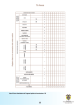
OWNER’S MANUAL
Models 600d/1100d
CONGRATULATIONS
Thank you for choosing a Directed Audio
power amplifier. Directed has been the
leader in high-quality and innovative
security products in the U.S. since
1990. Now we introduce to the car
audio industry the same winning
formula - products that meet the stringent standards of today’s mobile electronics enthusiast yet priced for
anyone’s budget. Featuring high-efficiency MOSFET power supplies, flexible
on-board crossovers, and state-of-the-art
audio design, Directed Audio amplifiers
will satisfy every music lover’s needs for
years to come. Your Directed Audio
power amplifier comes with a two year
limited warranty if it is installed by an
authorized DEI dealer. Amplifiers not
installed by an authorized Directed
dealer are covered by a one year partsand-labor limited warranty. Please save
your sales receipt and refer to the
warranty section of this manual for
complete details.
© 1999 Directed Electronics, Inc
TABLE OF CONTENTS
Installation Guidelines . . . . . . . . . . . . . . . . . . . . . . . . . . . .Page 2
Amplifier Connections . . . . . . . . . . . . . . . . . . . . . . . . . . . .Page 4
Amplifier Controls . . . . . . . . . . . . . . . . . . . . . . . . . . . . . . .Page 5
Speaker Wiring Diagrams . . . . . . . . . . . . . . . . . . . . . . . . .Page 6
Crossover Setting and Gain Adjustment . . . . . . . . . . . . . . . .Page 7
Synced Gain Operation . . . . . . . . . . . . . . . . . . . . . . . . . . .Page 8
External Synced Bridged Operation . . . . . . . . . . . . . . . . . . .Page 10
Specifications . . . . . . . . . . . . . . . . . . . . . . . . . . . . . . . . .Page 12
Warranty . . . . . . . . . . . . . . . . . . . . . . . . . . . . . . . . . . . . .Page 13
WARNING
High-powered car audio
systems may produce
sound pressure levels that exceed the
threshold at which hearing loss may
result.
© 1999 Directed Electronics, Inc
They may also impair a driver’s ability to
hear traffic sounds or emergency vehicles. Use common sense and practice
safe listening habits when listening to or
adjusting your audio system.
1
INSTALLATION GUIDELINES
1. Please read the owner’s manual
carefully before you install the
amplifier.
2. Disconnect the battery ground
terminal prior to making any electrical connections.
3. Check for any hazards or obstructions such as gas tanks, fuel or
brake lines, and wiring harnesses
before mounting the amplifiers.
4. Pick a mounting location that will
provide adequate access and ventilation and protect the amplifier
from heat, moisture, and dirt.
5. Avoid sharp metal areas when
routing cables to the amplifier, and
run RCA cables away from the
power cables and other potentially
noisy car harnesses.
6. The amplifier should be grounded
with a short, heavy gauge wire
connected directly to the car at a
bare metal surface. Make sure that
the metal area is part of the car
chassis or frame, not a separate
part with poor electrical connection
to the chassis.
7. Always fuse your power connection
at the battery within 8-10 inches of
the battery terminal. Use a fuse or
circuit breaker rated at about 5-10
2
more amps than the on board
fuse(s) of the amplifier(s). The
gauge of power wire used should
take into account the total current
draw of the system, and the length
of wire used. IASCA and other
autosound competition organizations have charts available for this;
you can also find a chart in the
MECP study guide. Minimum wire
gauge recommendations for the
individual amplifiers are listed on
the specification page. It is a good
idea to use the same gauge wire
for the amplifier ground that you
use for the power wire. Be sure to
examine the battery ground cable
of the vehicle and upgrade it to a
gauge of wire that can accommodate the extra load created by your
amplifier installation. Remember,
the amplifier can only deliver its
rated output when it is not current
limited by the power and ground
supply wires.
8. This amplifier is designed to drive a
speaker load that measures from 14 ohms. Keep in mind that heat is
the long-term enemy of automotive
electronics and that the lower your
speaker load, the more heat
© 1999 Directed Electronics, Inc
INSTALLATION GUIDELINES (continued)
is generated. For low impedance
speaker applications or restricted
ventilation installations, an external
cooling fan may be advisable.
9. Your connections to the amplifier’s
speaker and power terminals
should be made with crimped
spade lugs, and the battery and
ground connections to the vehicle
should be made with crimped ring
terminals of the appropriate size
(surface area is what counts);
soldering the terminals after
crimping is also recommended.
© 1999 Directed Electronics, Inc
10. Due to the high-frequency MOSFET
switching power supply used in all
Directed Audio amplifiers, filtering
the power cable is not generally
required (remember that the amp
can’t deliver full output if the power
supply is restricted). Proper
grounding of the signal source is
mandatory for the amplifier to
reach its performance peak. If the
RCA inputs are not grounded
adequately via the signal source,
electrical noise from the vehicle
may be picked up in the system.
3
AMPLIFIER CONNECTIONS
Refer to Figure 1 for details.
1. GROUND TERMINAL - connect this
terminal to the car chassis with a
short heavy gauge wire, DO NOT
CONNECT TO THE NEGATIVE TERMINAL
OF THE CAR BATTERY or to factory
chassis ground points already occupied by factory wires! Make sure
your chassis connection is secure by
removing any paint at the ground
point, and using a crimped, soldered
terminal at both ends of the wire.
2. REMOTE TERMINAL - connect this
terminal to the amplifier remote
output from your head unit or signal
source, if it provides one. You may
also use the power antenna output
wire from decks that do not have
separate amp remote outputs. Do
not connect this terminal to a
constant source of +12V.
3. +12V POWER TERMINAL - connect
this terminal to the positive terminal
of the car or separate audio system
battery. YOU MUST PROTECT THIS
WIRE WITH A FUSE or circuit breaker
located close to the battery.
4. POWER FUSE - protects the amplifier
against electrical damage. DO NOT
REPLACE THE FUSE WITH LARGER
AMPERAGE FUSES!
5. POWER/PROTECTION LED’S - the
green Power LED lights to indicate
normal operation. The red Protection
LED lights to indicate amp shutdown
due to thermal, short circuit, DC
offset, or over-current conditions.
6. SUBWOOFER OUTPUT TERMINALS
connect the subwoofers to these
terminals. The terminals are paralleled internally, but two sets are
provided for convenience in
connecting multiple subwoofers.
FIGURE 1—AMPLIFIER CONNECTIONS
4
© 1999 Directed Electronics, Inc
AMPLIFIER CONTROLS
Refer to Figure 2 for details.
1. RCA INPUT JACKS - accepts linelevel outputs from head units or
signal sources at voltages from 200
mV to 8 volts.
2. RCA INVERT IN JACK - use this jack
to accept signal from another
600d/1100d when operating in
synced slave mode. This jack also
supplies an in-phase output when
the unit is set to “Master”.
3. RCA INVERT OUT JACK - use this
jack to send an inverted phase
signal to another 600d/1100d
operating in synced slave mode.
4. MASTER/SLAVE INVERT SWITCH selects operating mode for synced
operation. For normal operation set
to master/0.
5. GAIN ADJUSTMENT - controls the
gain (input sensitivity) of the
amplifier.
6. SUBSONIC FILTER - Switchable variable subsonic filter prevents
damage to subwoofers in vented
and free-air applications.
7. BASS EQ - This switch activates an
8 dB bass boost circuit. Use as
necessary for low frequency
enhancement.
8. CROSSOVER FREQUENCY - controls
the cutoff frequency of the built-in
low-pass crossover.
9. OUTPUT PHASE INVERT SWITCH controls the output phase of the
amplifier. The output signal inverts
with the switch set to 180.
10. REMOTE SUB LEVEL - controls gains
of the amplifier.
FIGURE 2—AMPLIFIER CONTROLS
© 1999 Directed Electronics, Inc
5
SPEAKER WIRING DIAGRAMS
Single subwoofer connection
Speaker nominal impedance must be at least 1 ohm.
Two subwoofer connection
Parallel speaker nominal impedance must be at least 1 ohm. Amplifier parallels the
speaker terminals internally.
6
© 1999 Directed Electronics, Inc
CROSSOVER SETTINGS AND GAIN ADJUSTMENT
Your Directed Audio power amplifier needs to be adjusted carefully to achieve
maximum performance. These are some guidelines to follow when fine-tuning the
amplifier. Refer to the additional instructions on pages - for gain and crossover settings
in external synced mode.
• Because the 600d/1100d are only suited for subwoofer applications, the low-pass
crossover is active at all times. The crossover point is adjustable to allow more precise
system operation.
• Try and keep the setting low enough to prevent image smearing (you should not be
able to hear male voices from the subwoofer) but not so low as to create a gap
between the subwoofer and the mid-bass/midrange speakers. It will be to your advantage to spend some extra time with this adjustment, listening to familiar music or
system set-up discs to achieve the kind of musical reproduction that you prefer.
• The gain adjustment allows you to set proper signal match for clean, quiet amplifier
operation. Start by playing some music you are familiar with. With the gain adjustment on the amplifier in the middle of its rotation, bring up the volume on your head
unit to the 3/4 volume setting or until you start to hear distortion or clipping. If you
hear distortion before you reach the 3/4 volume setting of your head unit, reduce the
gain setting on the amplifier and start to raise the head unit volume again. When you
can listen to the music at or slightly above 3/4 on your head unit without audible
distortion, slowly raise the gain of the amplifier until distortion is heard, then back off
the gain until the distortion is not audible. This setting will allow you to reach full
output with all but the quietest of source material, while avoiding excessive noise in the
system.
• You should take into consideration the effect that gain adjustment has on system
frequency response and staging. Again, plan on spending some time with music that
you know getting the gain and crossover settings the way you like. Test discs and
analyzers may help with this process, but in the end it's your ears that count - listen
to the music!
© 1999 Directed Electronics, Inc
7
SYNCED GAIN OPERATION (control panel/inputs)
Refer to Figure 3 for details.
1. Master/Slave switch - set switch on
the first amp to Master/0 for most
systems. Set switch to Master/180
to invert the phase of both the
master and any synced amplifiers.
Set the Master/Slave switch on all
synced amplifiers to Slave.
2. Connect input signal from the head
unit or processor to the input RCA
jacks of the master amplifier.
3. Connect an RCA cable between the
INVERT IN RCA jack of the master
amplifier and the INVERT IN jack of
slaved amplifiers. Use “Y” adapters
to split the signal to each slaved
amplifier.
4. For best matching of input gains,
connect the unused INVERT OUT
RCA jack of the master amplifier to
the INVERT OUT RCA jack of the
slaved amplifiers. The slaved amplifier ignores the signal supplied to
the INVERT OUT jack, but the additional RCA cable connection helps
minimize ground potential differences between the master and
slave amplifier inputs and results in
a more accurate output voltage
match .
5. Set subsonic, EQ, and crossover
controls to the positions for best
results.
FIGURE 3
8
© 1999 Directed Electronics, Inc
SYNCED GAIN OPERATION (wiring diagram)
Refer to Figures 3 and 4 for details.
6. Remote sub level - connect a single
remote sub level control to each
amplifier using a telephone cable
splitter as shown in Figure 3.
7. The master amplifier’s gain control
(Figure 3) is used to set the overall
sub amp gain. The gain controls of
the slaved amplifiers are not functional and the overall gain is set by
the master amps gain and then by
the remote sub level control.
8. Connect the outputs of each amplifier to their separate subwoofer
load. In synced gain operation each
amplifier can drive a 1, 2, or
4 ohm load.
9. Remember that the amplifier parallels any speaker load connected to
the two pairs of supplied terminals.
You may safely connect one 2 ohm
subwoofer or 2 ohm combined load
to each of the two pairs of terminals or one 1 ohm subwoofer or 1
ohm combined subwoofer load to a
single pair of (+/-) terminals. Do
not connect combined loads of less
than 1 ohm to the amplifier.
FIGURE 4
© 1999 Directed Electronics, Inc
9
EXTERNAL SYNCED BRIDGED OPERATION(control panel/inputs)
Refer to Figure 5 for details.
1. Master/Slave switch - set switch
on the first amp to Master/0 for
most systems. Set switch to
Master/180 to invert the phase of
both the master and any synced
amplifiers. Set the Master/Slave
switch on all synced amplifiers to
Slave.
2. Connect input signal from the head
unit or processor to the input RCA
jacks of the master amplifier.
3. Connect an RCA cable between the
INVERT OUT RCA jack of the master
amplifier and the INVERT IN jack of
slaved amplifiers.
4. For best matching of input gains,
connect the unused INVERT IN RCA
jack of the master amplifier to the
INVERT OUT RCA jack of the slaved
amplifiers. The slaved amplifier
ignores the signal supplied to the
INVERT OUT jack, but the additional
RCA cable connection helps minimize ground potential differences
between the master and slave
amplifier inputs and results in a
more accurate output voltage
match.
5. The Bass EQ, subsonic switches and
frequency controls, and crossover
frequency conrols should be
matched on the both amps for best
results.
FIGURE 5
10
© 1999 Directed Electronics, Inc
EXTERNAL SYNCED BRIDGED OPERATION (wiring diagram)
Refer to Figures 5 and 6 for details.
6. Remote sub level - connect a single
remote sub level control to each
amplifier using a telephone cable
splitter as shown in Figure 5.
7. The master amplifier’s gain control
(Figure 5) is used to set the overall
sub amp gain. The gain control of
the slaved amplifier is not functional
and the overall gain is set by the
master amp’s gain and then by the
remote sub level control.
8. Connect the outputs of each amplifier to their separate subwoofer
load. In external synced bridged
operation each pair of amplifiers
can safely drive a 2 or 4 ohm load.
9. NOTE - you must connect the
negative subwoofer outputs of
the master amplifier to the negative subwoofer outputs of the
slaved amplifier as shown in
Figure 6. Use 12 AWG speaker wire
minimum to make this connection.
Otherwise the output of the two
synced amplifiers will be unstable
and they will not supply rated
power.
FIGURE 6
© 1999 Directed Electronics, Inc
11
SPECIFICATIONS 600D/1100D
model
RMS continuous power driven into 4 ohms from 20 to 250 Hz
@ 14.4 VDC THD at rated power/load
275
watts
0.4%
425
watts
0.5%
RMS continuous power driven into 2 ohms from 20 to 250 Hz
@ 14.4 VDC THD at rated power/load
400
watts
0.6%
750
watts
0.75%
RMS continuous power driven into 1 ohm from 20 to 250 Hz
@ 14.4 VDC THD at rated power/load
600
watts
0.8%
1100
watts
0.9%
Dynamic power rating (IHF-202 Standard) at minimum load
RMS continuous power driven into 4 ohms from 20 to 250 Hz
@ 14.4 VDC in synced bridge mode (two 600d)
750
watts
800
watts
1400
watts
1500
watts
RMS continuous power driven into 2 ohms from 20 to 250 Hz
@ 14.4 VDC in synced bridge mode (two 1100d)
1200
watts
2200
watts
Signal-to-Noise Ratio
Greater than 85 dB
Frequency Response
20-250 Hz +0, -1 dB
Damping Factor
50 (typical)
Crossover
Low-pass 18 dB/octave,
variable from 30 to 250 Hz
Subsonic Filter
Switchable 18 dB/octave,
variable from 20 to 250 Hz
Bass Equalization
Input Impedance
Input Sensitivity
Output Impedance
Supply Voltage
Fusing and Power
Cable Requirements (AWG)
(Per amp, trunk mounted)
12
600d 1100d
+8 dB, centered at 40Hz
20K ohms
Variable from 150 mV to 8 volt
1 to 4 ohms
10 to 16 VDC
60A 80A
#8
#4
© 1999 Directed Electronics, Inc
LIMITED TWO YEAR CONSUMER WARRANTY
Directed Electronics, Inc. (DEI ) promises to
the original purchaser, to replace this
product should it prove to be defective in
workmanship or material under normal use,
for a period of two years from the date of
purchase by the dealer as indicated by the
date code marking of the product
PROVIDED the product was installed by an
authorized DEI dealer. During this two year
period, there will be no charge for this
replacement PROVIDED the unit is returned
to DEI, shipping pre-paid. If the unit is
installed by anyone other than an authorized DEI dealer, the warranty period will be
1 year from date of purchase by the dealer
as indicated by the date code marking of
the product. During this 1 year period, there
will be no charge for this replacement
PROVIDED the unit is returned to DEI, shipping pre-paid. This warranty is non-transferable and does not apply to any unit that has
been modified or used in a manner contrary
to its intended purpose, and does not cover
damage to the unit caused by installation or
removal of the unit. This warranty is void if
the product has been damaged by accident
or unreasonable use, neglect, improper
service or other causes not arising out of
defects in materials or construction. ALL
WARRANTIES INCLUDING BUT NOT
LIMITED TO EXPRESS WARRANTY,
IMPLIED WARRANTY, WARRANTY OF
MERCHANTABILITY, FITNESS FOR PARTIC®
© 1999 Directed Electronics, Inc
ULAR PURPOSE, AND WARRANTY OF
NON-INFRINGEMENT OF INTELLECTUAL
PROPERTY ARE EXPRESSLY EXCLUDED TO
THE MAXIMUM EXTENT ALLOWED BY
LAW, AND DEI NEITHER ASSUMES NOR
AUTHORIZES ANY PERSON TO ASSUME
FOR IT ANY LIABILITY IN CONNECTION
WITH THE SALE OF THE PRODUCT. DEI
HAS ABSOLUTELY NO LIABILITY FOR ANY
AND ALL ACTS OF THIRD PARTIES
INCLUDING ITS AUTHORIZED DEALERS
OR INSTALLERS. Unit must be returned to
DEI, postage pre-paid, with: consumer’s
name, telephone number, and address,
authorized dealer’s name and address, and
product description. IN ORDER FOR THIS
WARRANTY TO BE VALID, YOUR UNIT
MUST BE SHIPPED WITH PROOF OF
INSTALLATION BY AN AUTHORIZED DEI
DEALER. ALL UNITS RECEIVED BY DEI FOR
WARRANTY REPAIR WITHOUT PROOF OF
DEI DEALER INSTALLATION WILL BE
COVERED BY THE LIMITED 1 YEAR PARTS
AND LABOR WARRANTY. Note: This
warranty does not cover labor costs for the
removal and reinstallation of the unit. BY
PURCHASING THIS PRODUCT, THE
CONSUMER AGREES AND CONSENTS THAT
ALL DISPUTES BETWEEN THE CONSUMER
AND DEI SHALL BE RESOLVED IN ACCORDANCE WITH CALIFORNIA LAWS IN SANDIEGO COUNTY, CALIFORNIA.
13
OTHER PRODUCTS AVAILABLE FROM:
®
•
•
•
•
CLASS D MONO AMPLIFIERS
2 CHANNEL AMPLIFIERS
4 AND 5 CHANNEL AMPLIFIERS
SIGNAL PROCESSORS
•
•
•
•
TUBE SUBWOOFERS
POWERED SUBWOOFERS
SINGLE AND DUAL VOICE COIL SUBWOOFERS
COAXIAL SPEAKERS
•
•
•
SINGLE AND DUAL VOICE COIL SUBWOOFERS
COAXIAL SPEAKERS
COMPONENT SPEAKER SYSTEMS
•
•
SINGLE AND DUAL VOICE COIL DIE-CAST SUBWOOFERS
COMPONENT NEODYMIUM SPEAKER SYSTEMS
•
SINGLE AND DUAL VOICE COIL DIE-CAST SUBWOOFERS
•
•
•
•
•
HIGH PERFORMANCE POWER CABLES
PREMIUM SPEAKER/AUDIO CABLES AND ADAPTERS
POWER CAPACITORS
GOLD-PLATED POWER DISTRIBUTION AND FUSING BLOCKS
GOLD-PLATED POWER AND SPEAKER TERMINALS
Always use a
© 1999 Directed Electronics, Inc • Vista, CA 92083 • All Rights Reserved
DEI is a proud member of
G45014 9/99