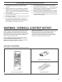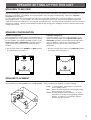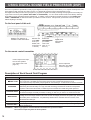
1
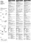
AV-90PY
Natural Sound Digital Sound Field Processing Amplifier
5 Speaker Configuration
100W + 100W (8Ω) RMS Output Power, 0.08% THD, 20-20,000 Hz (Front)
25W (8Ω) RMS Output Power, 0.08% THD, 20-20,000 Hz (Center)
25W + 25W (8Ω) RMS Output Power, 0.3% THD, 1,000 Hz (Rear)
Digital Sound Field Processor; 4 Programs for Digital Sound Field Processing
and 2 Programs for Dolby Surround (DOLBY PRO LOGIC AND ENHANCED)
Automatic Input Balance Control for Dolby Surround
Video Signal Input/Output Capability
Programmable Remote Control Transmitter
Thank you for selecting this YAMAHA stereo amplifier.
CAUTION
RISK OF ELECTRIC SHOCK
DO NOT OPEN
OWNER’S MANUAL
CAUTION: TO REDUCE THE RISK OF
ELECTRIC SHOCK, DO NOT REMOVE
COVER (OR BACK), NO USER-SERVICEABLE
PARTS INSIDE, REFER SERVICING TO
QUALIFIED SERVICE PERSONNEL.
CONTENTS
Safety Instructions..................................... 2
Caution...................................................... 3
Warning..................................................... 3
Supplied Accessories................................ 3
Profile of This Unit..................................... 4
Speaker Setting-up for This Unit ............... 5
Yamaha Active Servo Technology ............ 6
Connections .............................................. 7
Adjustment Before Operation.................... 10
Operations................................................. 13
Using Digital Sound Field Processor
(DSP) ........................................................ 16
Remote-Control Transmitter...................... 20
Remote-Control “Learning” Function......... 21
Notes about the Remote Control
Transmitter ................................................ 22
Troubleshooting ........................................ 23
Specifications ............................................ 24
IMPORTANT!
Please record the serial number of this
unit in the space below.
• Explanation of Graphical Symbols
Model:
Serial No.:
The serial number is located on the rear
of the unit.
Retain this Owner’s Manual in a safe
place for future reference.
WARNING
TO REDUCE THE RISK OF FIRE OR
ELECTRIC SHOCK, DO NOT EXPOSE
THIS UNIT TO RAIN OR MOISTURE.
The lightning flash with arrowhead
symbol, within an equilateral triangle,
is intended to alert you to the
presence of uninsulated “dangerous
voltage” within the product’s
enclosure that may be of sufficient
magnitude to constitute a risk of
electric shock to persons.
The exclamation point within an
equilateral triangle is intended to alert
you to the presence of important
operating and maintenance
(servicing) instructions in the
literature accompanying the
appliance.
1
SAFETY INSTRUCTIONS
1
2
3
4
5
6
6A
7
8
9
Read Instructions – All the safety and operating
instructions should be read before the unit is operated.
Retain Instructions – The safety and operating instructions
should be retained for future reference.
Heed Warnings – All warnings on the unit and in the
operating instructions should be adhered to.
Follow Instructions – All operating and other instructions
should be followed.
Water and Moisture – The unit should not be used near
water – for example, near a bathtub, washbowl, kitchen
sink, laundry tub, in a wet basement, or near a swimming
pool, etc.
Carts and Stands – The unit should be used only with a
cart or stand that is recommended by the manufacturer.
A unit and cart combination should
be moved with care.
Quick stops, excessive force,
and uneven surfaces may cause
the unit and cart combination to
overturn.
Wall or Ceiling Mounting – The unit should be mounted to
a wall or ceiling only as recommended by the
manufacturer.
Ventilation – The unit should be situated so that its
location or position does not interfere with its proper
ventilation. For example, the unit should not be situated
on a bed, sofa, rug, or similar surface, that may block the
ventilation openings; or placed in a built-in installation,
such as a bookcase or cabinet that may impede the flow
of air through the ventilation openings.
Heat – The unit should be situated away from heat
sources such as radiators, stoves, or other appliances that
produce heat.
10 Power Sources – The unit should be connected to a power
11
12
13
14
15
A.
B.
C.
D.
E.
16
17
18
supply only of the type described in the operating
instructions or as marked on the unit.
Power-Cord Protection – Power-supply cords should be
routed so that they are not likely to be walked on or
pinched by items placed upon or against them, paying
particular attention to cords at plugs, convenience
receptacles, and the point where they exit from the unit.
Cleaning – The unit should be cleaned only as
recommended by the manufacturer.
Nonuse Periods – The power cord of the unit should be
unplugged from the outlet when left unused for a long
period of time.
Object and Liquid Entry – Care should be taken so that
objects do not fall into and liquids are not spilled into the
inside of the unit.
Damage Requiring Service – The unit should be serviced
by qualified service personnel when:
The power-supply cord or the plug has been damaged;
or
Objects have fallen, or liquid has been spilled into the unit;
or
The unit has been exposed to rain; or
The unit does not appear to operate normally or exhibits a
marked change in performance; or
The unit has been dropped, or the cabinet damaged.
Servicing – The user should not attempt to service the unit
beyond those means described in the operating
instructions. All other servicing should be referred to
qualified service personnel.
Power Lines – An outdoor antenna should be located
away from power lines.
Grounding or Polarization – Precautions should be taken
so that the grounding or polarization is not defeated.
FCC INFORMATION
1. IMPORTANT NOTICE : DO NOT MODIFY THIS UNIT!
This product, when installed as indicated in the
instructions contained in this manual, meets FCC
requirements. Modifications not expressly approved by
Yamaha may void your authority, granted by the FCC, to
use the product.
2. IMPORTANT : When connecting this product to
accessories and/or another product use only high quality
shielded cables. Cable/s supplied with this product
MUST be used. Follow all installation instructions.
Failure to follow instructions could void your FCC
authorization to use this product in the USA.
3. NOTE : This product has been tested and found to
comply with the requirements listed in FCC Regulations,
Part 15 for Class “B” digital devices. Compliance with
these requirements provides a reasonable level of
assurance that your use of this product in a residential
environment will not result in harmful interference with
other electronic devices.
This equipment generates/uses radio frequencies and, if
not installed and used according to the instructions
found in the users manual, may cause interference
harmful to the operation of other electronic devices.
2
Compliance with FCC regulations does not guarantee that
interference will not occur in all installations. If this product
is found to be the source of interference, which can be
determined by turning the unit “OFF” and “ON”, please try
to eliminate the problem by using one of the following
measures:
Relocate either this product or the device that is being
affected by the interference.
Utilize power outlets that are on different branch (circuit
breaker or fuse) circuits or install AC line filter/s.
In the case of radio or TV interference, relocate/reorient the
antenna. If the antenna lead-in is 300 ohm ribbon lead,
change the lead-in to co-axial type cable.
If these corrective measures do not produce satisfactory
results, please contact the local retailer authorized to
distribute this type of product. If you can not locate the
appropriate retailer, please contact Yamaha Electronics
Corp., U.S.A. 6722 Orangethorpe Ave, Buena Park, CA
90620.
The above statements apply ONLY to those products
distributed by Yamaha Corporation of America or its
subsidiaries.
CAUTION: READ THIS BEFORE OPERATING YOUR UNIT
1
2
3
4
5
To ensure the finest performance, please read this
manual carefully. Keep it in a safe place for future
reference.
Install your unit in a cool, dry, clean place – away from
windows, heat sources, and too much vibration, dust,
moisture or cold. Avoid sources of hum (transformers,
motors). To prevent fire or electrical shock, do not expose
to rain and water.
Do not operate the unit upside-down. It may overheat,
possibly causing damage.
Never open the cabinet. If a foreign object drops into the
set, contact your dealer.
Do not use force on switches, knobs or cords. When
moving the set, first turn the unit off. Then gently
disconnect the power plug and the cords connecting to
other equipment. Never pull the cord itself.
6
7
8
9
Do not attempt to clean the unit with chemical solvents;
this might damage the finish. Use a clean, dry cloth.
Always set the volume control to “–
” before starting the
audio source play: increase the volume gradually to an
appropriate level after the play is started.
Be sure to read the “Troubleshooting” section on common
operating errors before concluding that your unit is faulty.
Do not connect audio equipment to the AC outlets on the
rear panel if that equipment requires more power than the
outlets are rated to provide.
WARNING: CHEMICAL CONTENT NOTICE!
The solder used in the manufacture of this product contains
LEAD. In addition, the electrical/electronic and/or plastic
(where applicable) components may also contain traces of
chemicals found by the California Health and Welfare Agency
(and possibly other entities) to cause cancer and/or birth
defects or other reproductive harm.
IMPORTANT MESSAGE: Yamaha strives to produce products
that are both user safe and environmentally “friendly”. We
sincerely believe that our products meet these goals.
However, in keeping with both the spirit and the letter of
various statutes we have included the preceding messages
and others in various locations in this manual.
DO NOT REMOVE ANY ENCLOSURE COMPONENTS!
There are no user serviceable parts inside.
All service should be performed by a service representative
authorized by Yamaha to perform such service.
SUPPLIED ACCESSORIES
After unpacking, check that the following parts are contained.
Batteries (size AA, LR6, AM-3)
Remote Control Transmitter
User Program Sheets
3
PROFILE OF THIS UNIT
You are the proud owner of Yamaha AV-90PY, the stereo amplifier –an extremely sophisticated audio component. The Digital
Sound Field Processor (DSP) built in this unit takes full advantage of Yamaha’s undisputed leadership in the field of digital audio
processing to bring you a whole new world of listening experiences. Follow the instructions in this manual carefully when setting up
your system, and this unit will sonically transform your room into a wide range of listening environments –movie theater, concert
hall, and so on. In addition, you get incredible realism from Dolby-encoded video sources using the built-in Dolby Pro Logic
Surround Decoder.
Rather than tell you about the wonders of digital sound field processing, however, let’s get right down to the business of setting up
the system and trying out its many capabilities. Please read this operation manual carefully and store it in a safe place for later
reference.
Digital Sound Field Processing
What is it that makes live music so good? Today’s advanced
sound reproduction technology lets you get extremely close to
the sound of a live performance, but chances are you’ll still
notice something missing: the acoustic environment of the live
concert hall. Extensive research into the exact nature of the
sonic reflections that create the ambience of a large hall has
made it possible for Yamaha engineers to bring you this same
sound in your own listening room, so you’ll feel all the sound of
a live concert.
What’s more, our technicians, armed with sophisticated
measuring equipment, have even made it possible to capture
the acoustics of a variety of actual concert hall, theater, etc. to
allow you to accurately recreate one of several actual live
performance environments, all in your own home.
Dolby Pro Logic Surround
The Dolby Pro Logic Surround Decoder program lets you
experience the dramatic realism and impact of Dolby Surround
movie theater sound in your own home. Dolby Pro Logic gets
its name from its professional-grade steering logic circuitry,
which provides greater effective channel separation for a much
higher degree of realism than the “passive” Dolby Surround
circuits found in today’s typical home audio/video equipment.
Dolby Pro Logic Surround provides a true center channel, so
that there are four independent channels, unlike passive Dolby
Surround which has in effect only three channels: left, right,
and rear. This center channel allows listeners seated in even
less-than-ideal positions to hear the dialog originating from
action on the screen while getting a stereo effect as well.
“ENHANCED” Dolby Pro Logic Surround
The AV-90PY has a second mode of Dolby Pro Logic Surround
processing called “Enhanced Dolby Pro Logic Surround”
processing. Enhanced Dolby Pro Logic Surround processing
recreates the surround effect of a movie theater, effectively
duplicating their multiple surround loudspeaker system,
completely surrounding the listener with the sounds of the
action taking place on the screen.
4
This Dolby Pro Logic Surround Decoder employs a digital
signal processing system. This system increases sound
stability at each channel and minimizes crosstalk between
channels, compared to conventional analog Dolby signal
processing.
In addition, this unit features a built-in automatic input balance
control. This circuit always presents you the best surround
conditions without performing manual adjustments.
SPEAKER SETTING UP FOR THIS UNIT
SPEAKERS TO BE USED
This unit is designed to provide the best sound-field quality with 5 speaker configuration. The speakers to be used with this unit will
be mainly front speakers, rear speakers, and a center speaker. (You can delete a center speaker. Refer to the “4-Speaker
Configuration” shown below.)
The front speakers are used for the output of the main source sound and the effect sound. They will probably be your present
stereo speaker system. The rear speakers are used for the output of the effect sound. And the center speaker is used for the
output of the center sound (dialogue etc.) encoded with the Dolby Surround. The rear and center speakers do not need to be equal
with the front speakers. However, all the speakers should have high enough power handling to accept the maximum output of this
unit that will drive them.
SPEAKER CONFIGURATION
5-Speaker Configuration
This configuration is the most effective and recommended. In
this configuration, the center speaker is necessary as well as
the rear speakers. If the digital sound field program is in the
DOLBY PRO LOGIC or ENHANCED, conversations will be
output from the center speaker and the ambience will be
excellent.
●
Set the center mode to the “NORMAL” or “WIDE” position.
(For details, refer to the page 11.)
Front L
Center
4-Speaker Configuration
The center speaker is not used in this configuration. If the
digital sound field program is in the DOLBY PRO LOGIC or
ENHANCED, the center sound is output from the left and the
right front speakers. However, the sound effect of other
programs can be the same as that of the 5-speaker
configuration.
●
Be sure to set the center mode to the “PHANTOM” position.
(For details, refer to the page 11.)
Front R
Front L
Dialogue
Dialogue
Surround sound
Surround sound
Rear L
Rear R
Rear L
Front R
Rear R
SPEAKER PLACEMENT
The recommanded speaker configuration, the 5-speaker configuration, will require two speaker pairs: front speakers (your normal
stereo speakers), and rear speakers, plus a center speaker. When you place these speakers, refer to the following.
Front:
In normal position. (The position of your present
stereo speaker system.)
Rear: Behind your listening position, facing slightly inward.
Nearly six feet up from the floor.
Center: Precisely between the front speakers. (To avoid
interference to TV sets, use a magnetically shielded
speaker. If, however, it is not effective, keep the
speaker away from TV sets.)
Front R
Center
Front L
TV set
Rear R
Rear L
5
YAMAHA ACTIVE SERVO TECHNOLOGY
High-amplitude
bass sound
Cabinet
Air woofer
(Helmholtz resonator)
Port
Active Servo
Processing Amplifier
Signals
Negative-impedance
output drive
Signals of low amplitude
The theory of the Active Servo Technology is based upon two
major factors, the Helmholtz resonator and negativeimpedance drive. Active Servo Processing speakers
reproduce the bass frequencies through an “air woofer”, which
is a small port or opening in the speaker’s cabinet. This
opening is used instead of, and performs the functions of, a
woofer in a conventionally designed speaker system. Thus,
signals of low amplitude within the cabinet can, according to
the Helmholtz resonance theory, be output from this opening
as waves of great amplitude if the design is such that the size
of the opening and the volume of the cabinet are in the correct
proportion to satisfy a certain ratio.
In order to accomplish this, moreover, the amplitudes within
the cabinet must be both precise and of sufficient power
because these amplitudes must overcome the “load”
presented by the air that exists within the cabinet.
6
Thus it is this problem that is resolved through the
employment of a design in which the amplifier functions to
supply the signals. If the electrical resistance of the voice coil
is reduced to zero, the movement of the speaker unit would
become linear with respect to signal voltage, and, to
accomplish this, a special negative-impedance output-drive
amplifier for subtracting output impedance of the amplifier is
used.
By employing negative-impedance drive circuits, the amplifier
is able to generate precise, low-amplitude low-frequency
waves with superior damping characteristics, and these waves
are then radiated from the cabinet opening as high-amplitude
signals. The system can, therefore, by employing the
negative-impedance output drive amplifier and a speaker
cabinet with the Helmholtz resonator, reproduce an extremely
wide range of frequencies (28 Hz – 20 kHz) with amazing
sound quality and less distortion.
The features described above, then, are combined to be the
fundamental structure of the Active Servo Technology.
CONNECTIONS
Before attempting to make any connections to or from this unit, be sure to first switch OFF the power to this unit and to any other
components to which connections are being made.
CONNECTIONS WITH OTHER COMPONENTS
When making connections between this unit and other components, be sure all connections are made correctly, that is to say L
(left) to L, R (right) to R, “+” to “+” and “–” to “–”. Also, refer to the owner’s manual for each component to be connected to this unit.
Rear speakers
Center speaker
LD player
Video cassette recorder 1
Left
Right
Compact disc player
Refer to “SETTING OF
THE YST SELECTOR”
on page 9.
(U.S.A. model)
Turntable
Tuner
To AC outlet
Tape deck 1
Left
Right
Video cassette recorder 2
or tape deck 2
Monitor TV
Front speakers
: Refer to “About the accessory terminals” on page 8.
7
CONNECTING SPEAKERS
aConnect the SPEAKERS terminals to your speakers with wire
of the proper gauge, cut to be as short as possible. If the
connections are faulty, no sound will be heard from the
speakers. Make sure that the polarity of the speaker wires is
correct, that is, + and – markings are observed. If these wires
are reversed, the sound will be unnatural and will lack bass.
Do not let the bare speaker wires touch each other and do
not let them touch the metal parts of this unit as this could
damage this unit and/or speakers.
● Use speakers with the specified impedance shown on the
rear of this unit.
How to Connect:
Red: positive (+)
Black: negative (–)
1 Press and hold the tab.
2 Insert the bare wire.
[Remove approx. 5mm
(1/4") insulation from
the speaker wires.]
3 Release the tab and
secure the wire.
ABOUT THE ACCESSORY TERMINALS
AC OUTLETS
FRONT OUT terminals
Use these to connect the power cords from your components
to this unit.
The power to the SWITCHED outlets is controlled by this unit’s
POWER switch or the provided remote-control transmitter’s
POWER key. These outlets will supply power to any
component whenever this unit is turned on.
The maximum power (total power consumption of
components) that can be connected to the SWITCHED AC
OUTLETS is 100 watts.
These terminals are for front-channel line output. Leave the
jumper bars connected to FRONT IN terminals when you use
the built-in amplifier.
However, if you drive front speakers with an external stereo
power amplifier, remove the jumper bars and connect input
terminals of the external amplifier (MAIN IN or AUX terminals
of a power amplifier or an integrated amplifier) to these
terminals.
FRONT IN terminals
REMOTE CONTROL (PHONO) connector
S
If you have a YAMAHA turntable with the
mark, connect
it to this connector by using the cable provided with the
turntable. This connection allows you to control the turntable
from the provided remote control transmitter.
GND terminal (For turntable use)
Connecting the ground wire of the turntable to this terminal will
minimize hum, but in some cases better results may be
obtained with the ground wire disconnected.
8
These terminals are for line input to the built-in front-channel
amplifier. Leave the jumper bars connected to FRONT OUT
terminals when you use the built-in amplifier.
However, if you drive front speakers with an external stereo
power amplifier, remove the jumper bars.
CENTER OUT terminal
This terminal is for center-channel line output. There is no
connection to this terminal when you use the built-in amplifier.
However, if you drive a center speaker with an external power
amplifier, connect input terminal of the external amplifier to this
terminal.
If you use the built-in amplifier and the external power amplifier
at the same time, the sound will be output through both
speakers.
SETTING OF THE YST SELECTOR
This unit can drive conventional speakers and YAMAHA Active Servo Processing speakers. Switch the YST SELECTOR (located
on the rear panel of this unit ) to the appropriate position referring to the following.
CONVENTIONAL position: To drive conventional speakers .
YST-1 position, YST-2 position: To drive YAMAHA Active Servo Processing speakers.
For detailed information on which type of speakers is appropriate to each position, refer to the rear
panel of the speakers to be used.
Switch
Notes
• Incorrect connection or miss-setting of the switch could damage this unit and the connected speakers.
• Be absolutely sure that this unit’s power is OFF before setting the switch and making the amplifier-to-speakers
connections.
9
ADJUSTMENT BEFORE OPERATION
1
2
3
Speaker balance adjustment
Using the built-in test tone generator, this procedure lets you adjust the sound output level balance between the front, center, and
rear speakers. With this adjustment, the sound output level heard at the listening position will be the same from each speaker.
This is important for the best performance of digital sound field processor.
1
From the step 4, the adjustment should be done with the
remote control transmitter at your listening position.
(The adjustment can be done also with the controllers on
the front panel of this unit. However, the result may not be
as satisfactory as from your listening position.)
VOLUME
0
— dB
Set to the “
∞” position.
2
—
5
BASS
TREBLE
0
0
—
5+
5
5+
4
USER
RS
LEARN
Set to the “0” position.
3
Set to the “RS” position.
BALANCE
5
0
POWER
L 5
5 R
Set to the “0” position.
10
For the detailed information on the remote-control transmitter, refer to “REMOTE CONTROL TRANSMITTER” on the page 20.
9
6
PRO LOGIC
1
ENHANCED
2
or
7
Turn up the volume by using the remote-control
transmitter. You will hear a test tone (like pink noise)
from the left front speaker, then the center speaker,
then the right front speaker, then the rear speakers,
for about two seconds each. The display illumination
changes as shown below.
Select the center mode depending on your speaker
configuration.
(Refer to “SPEAKER CONFIGURATION” on page
5.)
CENTER
MODE
NORMAL
WIDE
PHANTOM
On the feature of each mode, refer to the “Note” shown
below.
8
* The test tone from the left rear speaker and the right rear
speaker will be heard at the same time.
Note
In the step 7, when you select the center mode, note the
following.
For 5 speaker configuration
NORMAL: Select this mode when you use the center speaker
smaller sized than the front speakers. In this mode,
the bass tone will be output from the front
speakers.
WIDE:
Select this mode when you use the center speaker
approximately same sized as the front speakers.
Flashes on and off continuosly.
For 4 speaker configuration
PHANTOM: Select this mode when you do not use the center
speaker. The center sound will be output from the
left and the right front speakers.
11
10
the BALANCE control so that the effect sound
10 Adjust
output level of the left front speaker and the right front
13
speaker are the same.
Stop flashing and disappears.
BALANCE
0
On the front panel of the unit.
L 5
5 R
the sound output level of the center speaker the
11 Make
same as that of the front speakers with the CENTER
LEVEL key.
Illuminates.
Adjustable.
the sound output level of the rear speakers the
12 Make
same as that of the front speakers with the REAR
LEVEL key.
Illuminates.
Adjustable.
12
Notes
● Once you have completed these adjustments, use only this
unit’s VOLUME control to adjust listening volume. Do not
change any other volume settings in this unit.
● If you use external power amplifiers, their volume controls
may also be adjusted to achieve proper balance.
● In the step 11, if the center mode is in the “PHANTOM”, the
sound output level of the center speaker can not be
adjusted. Because in this mode, the center sound is
automatically output from the left and right front speakers.
2
OPERATIONS
Display
3
1,5
PHONES
6
To play a source
VOLUME
1
0
— dB
Set to the “
∞” position.
2
3
Select a desired input source.
(For video sources, turn the TV/monitor ON.)
* The indicator corresponding to the
selected input source will illuminate.
4
Notes
In the step 3, if two or more program sources are selected at
the same time (by using input selectors), be sure to remember
the priority order of the input sources.
Priority order of audio sources: 1) TAPE 1 MON, 2) VCR 1
MON, 3) VCR 2 MON/TAPE 2 MON, and 4) LD/TV, TUNER,
CD or PHONO.
Priority order of video sources: 1) VCR 1 MON, 2) VCR 2
MON/TAPE 2 MON, and 3) LD/TV.
● If you select LD/TV, TUNER, CD or PHONO, be sure that
TAPE MON and/or VCR MON input selectors are not being
selected.
● If you select TAPE 1 MON and VCR 1 (or 2) MON input
selectors at the same time, the result will be the visual of the
VCR and the sound from the audio tape.
● If you select both LD/TV and TAPE MON input selectors at
the same time, the result will be the visual of the LD player
and the sound from the audio tape.
● Once you play the LD player, its visual will not be
interrupted even if other input selectors except VCR MON
input selectors are selected.
● If you select TAPE 1 MON and VCR 1 (or 2) MON input
selectors, and another input selector at the same time, the
result will be the visual of the VCR and the sound from the
audio tape.
Play the source.
VOLUME
5
0
— dB
Adjust to the desired output level.
6
If desired, adjust the BASS, TREBLE, BALANCE
controls, etc.(Refer to page 15.) and use the digital
sound field processor. (Refer to page 16.)
13
1,4
2
To record a source to tape
1
4
Select the source to be recorded.
* To dub from tape to tape, refer to the “Notes” shown
below.
* When selecting LD/TV, TUNER, CD or PHONO, be sure
the TAPE 1 MON, VCR 1 MON or VCR 2/TAPE 2 MON
input selector(s) are not also selected.
2
3
14
Play the source and then turn the VOLUME control
up to confirm the input source.
Set the tape deck or VCR in the recording mode.
To monitor the audio and/or video signals being
recorded, press the input selector button for the audio
or video tape recorder being used to make the
recording.
* A red selector switch indicator takes priority over an
orange indicator.
Notes
There are three ways to dub from tape to tape:
1) To record from VCR 2 or tapedeck 2 to VCR 1, press
both the VCR 2 MON/TAPE 2 MON and VCR 1 MON
selector switches (so both the indicators are lighted red).
2) To record from VCR 2 or tapedeck 2 to tapedeck 1, press
both the VCR 2 MON/TAPE 2 MON and TAPE 1 MON
selector switches (so both the indicators are lighted red).
3) To record from VCR 1 to tapedeck 1, press both the VCR
1 MON and TAPE 1 MON selector switches (so both the
indicators are lighted red).
● DSP, VOLUME, BASS, TREBLE and BALANCE contol
settings have no effect on the material being recorded.
●
Adjusting the BALANCE control
Adjust the balance of the output volume to the left and right
speakers to compensate for sound imbalance caused from
speaker location or listening room conditions.
Adjusting the BASS and TREBLE
controls
BALANCE
BASS
TREBLE
0
0
0
L 5
—
5 R
Note
This control is effective only on the sound from the front
speakers.
BASS
5
5+
—
5
5+
: Turn this clockwise to increase (or counterclockwise to decrease) the low frequency
response.
TREBLE : Turn this clockwise to increase (or counterclockwise to decrease) the high frequency
response.
Note
These controls are effective only on the sound from the front
speakers.
When you listen with headphones
Connect the headphones to the PHONES jack. You can listen
to the main sound through the headphones.
PHONES
15
USING DIGITAL SOUND FIELD PROCESSOR (DSP)
This unit incorporates a sophisticated, multi-program digital sound field processor, which allows you to expand and shape the audio
sound field from both the audio and video sources, for a theater-like experience in the listening/viewing room.
This digital sound field processor has 6 programs; 4 programs for digital sound field processing and 2 programs for the Dolby Pro
Logic Surround sound system (DOLBY PRO LOGIC and ENHANCED). You can create excellent audio sound field by selecting
the suitable program and adding desired adjustments. In addition, when the digital sound field program is in the DOLBY PRO
LOGIC or ENHANCED, the built-in automatic input balance control functions. This presents you the best surround condition
without adjusting it manually.
On the front panel of this unit
Displays your selection on
the DSP or other informations.
Sets the unit
to the TEST
mode. (For
details, refer
to the page 10,
11 and 12.)
Selects the
CENTER MODE.
(For details,
refer to the
page 10, 11
and 12.)
Digital sound
field program
selector
On the remote control transmitter
Used to adjust sound output
level of each speaker.
(For details, refer to the
page 19.)
Used to adjust the
delay time. (For details,
refer to the page 18.)
Description of Each Sound Field Program
PROGRAM
PRO LOGIC
ENHANCED
CONCERT VIDEO
MONO MOVIE
FEATURE
This program is effective on the play of the sources encoded with the Dolby Surround.
The employment of the digital signal processing system improves crosstalk and transfers the sound
source more smoothly and precisely,comparing with the conventional type. A stable movie sound field is recreated.
This program is effective on the play of the sources encoded with the Dolby Surround.
Enhancing the “Normal” Dolby Pro Logic, the DSP technology simulates the multi-surround speaker
systems of the 35 mm film theater, so widening the surrounded-sound field with greater presence.
This program is effective on music videos and excellent in depth and clarity for vocals. For opera, the
orchestra and stage are ideally recreated, so letting you feel as if you were in an actual concert hall.
This program is designed specifically to enhance mono source programs. Compared to a strictly mono
setting, the sound image created in this mode is wider and slightly forward of the speaker pair, lending an
immediacy to the overall sound. It is particularly effective when used with old mono movies, news
broadcasts and dialogue.
ROCK CONCERT
This program will suit to rock music. A big, powerful sound is reproduced lively and dynamically.
CONCERT HALL
In this program, the center seems even more deeply behind the front speaker pair, creating an expansive,
large hall ambience.
OFF Switch : When any program is not used with the selected source, press this switch.
The sound is output only from the front speakers.
16
Notes on Operation of Sound Field Programs
●
In the CONCERT VIDEO, MONO MOVIE, ROCK CONCERT
and CONCERT HALL, no sound is heard from the center
speaker.
●
When the monaural sound source is played in the DOLBY
PRO LOGIC or ENHANCED, no sound is heard from the
front speakers and the rear speakers. Sound is heard only
from the center speaker. However, if the center mode is in
the PHANTOM, the front speakers output the sound of the
center speaker.
●
If you connect an external amplifier to this unit, see if it has a
built-in surround sound or ambience circuitry. If it does, then
be sure that the surround or ambience circuitry on that
amplifier is off while you are using the digital sound field
processor’s Dolby Pro Logic Surround decoding function.
●
When this unit is in the Dolby Pro Logic Surround mode, if
the main-source sound is considerably altered by
overadjustment of the BASS or TREBLE controls, the
relationship with the center and rear channels may produce
an unnatural effect.
Description of Dolby Pro Logic Surround
DOLBY PRO LOGIC SURROUND: This unit employs the
Dolby Pro Logic Surround system. This system is similar to
professional Dolby Stereo decoders used in movie theaters.
The Dolby Pro Logic Surround system, by employing a fourchannel system, divides the input signals into four levels: the
left and right main channels, the center channel (to characterize
dialogue), and the rear surround-sound channels (to
characterize sound effects, background noise and other ambient
noise).
Dolby Surround is encoded on the sound track of commercially
available video cassettes and video discs as well. When you
play a source encoded with Dolby Surround on your home video
system, the Dolby Pro Logic Surround mode on this unit
decodes the signal and feeds the surround-sound effects.
The Dolby Pro Logic Surround mode may not be always
effective on video sources not encoded with Dolby Surround.
Manufactured under license from Dolby Laboratories Licensing
Corporation. Additionally licensed under one or more of the
following patents: U.S. numbers 3,632,886, 3,746,792, and
3,959,590; canadian numbers 1,004,603 and 1,037,877.
“Dolby” and the double-D symbol are trademarks of Dolby
Laboratories Licensing Corporation.
17
To play source with the digital sound field processor
2
1
Follow the step 1, 2, 3, 4, and 5 shown in
“OPERATION” on page 13.
2
Select a desired program suitable for the source.
3
If desired, adjust the delay time and the output level of
each speaker. (For details, refer to the corresponding
descriptions on this page and the next page.)
Note
If you prefer to cancel the selected program, press the OFF
switch. The sound will be the normal 2-channel stereo without
surround sound effect.
PRO LOGIC
The corresponding indicator will illuminate.
Adjustment of DELAY TIME
You can adjust the time difference between the beginning of
the source sound and the beginning of the effect sound with
the DELAY TIME control.
The DELAY TIME control is effective with all programs.
By applying more or less delay, sound effects, background
noise, and ambient noise coming at you from the rear speakers
can be enhanced or subdued for extra effect.
PRO LOGIC: from 15 to 30 milliseconds
(Preset value: 20 milliseconds)
2 ENHANCED: from 15 to 30 milliseconds
(Preset value: 20 milliseconds)
3 CONCERT VIDEO: from 1 to 100 milliseconds
(Preset value: 25 milliseconds)
4 MONO MOVIE: from 1 to 100 milliseconds
(Preset value: 25 milliseconds)
5 ROCK CONCERT: from 1 to 100 milliseconds
(Preset value: 15 milliseconds)
6 CONCERT HALL: from 1 to 100 milliseconds
(Preset value: 30 milliseconds)
Adjustable.
1
18
●
By continuously pressing “+” or “–” of the DELAY TIME
control, the value changes continuously.
However, the value stops changing momentarily at the
preset point.
Note
Adding too much delay will cause an unnatural effect with
some sources. Experiment with the DELAY TIME control to
create an effect that you find most suitable.
Adjustment of the FRONT EFFECT LEVEL
If desired, you can adjust the effect sound output level of the
front speakers with this control. The output level is preset to be
80. However, you can adjust the level between 1 and 100.
●
If the digital sound field program is in the DOLBY PRO
LOGIC, the FRONT EFFECT LEVEL control does not
function.
●
Once the output level is adjusted, the level value will be
common among all the digital sound field programs except
the DOLBY PRO LOGIC .
●
If any digital sound field program is not used, the FRONT
EFFECT LEVEL control does not function.
●
By continuously pressing “+” or “–” of the CENTER LEVEL
control, the level value changes continuously. However, the
value stops changing momentarily at the point which was
once set in the TEST mode.
●
If the digital sound field program is in the CONCERT
VIDEO, MONO MOVIE, ROCK CONCERT or CONCERT
HALL, the CENTER LEVEL control can not function.
●
Once the output level is adjusted, the level value will be
common among the DOLBY PRO LOGIC and ENHANCED.
●
If any digital sound field program is not used, the CENTER
LEVEL control does not function.
●
By continuously pressing “+” or “–” of the REAR LEVEL
control, the level value changes continuously. However, the
value stops changing momentarily at the point which was
once set in the TEST mode.
●
Once the output level is adjusted, the level value will be
common among all the digital sound field programs.
●
If any digital sound field program is not used, the REAR
LEVEL control does not function.
Adjustable. Illuminates.
Adjustment of the CENTER LEVEL
If desired, you can adjust the sound output level of the center
speaker with this control even if the output level is already set
in “Speaker balance adjustment” on the page 10.
Adjustable. Illuminates.
Adjustment of the REAR LEVEL
If desired, you can adjust the sound output level of the rear
speakers with this control even if the output level is already set
in “Speaker balance adjustment” on the page 10.
Adjustable. Illuminates.
Note
The values of the DELAY TIME, the FRONT EFFECT LEVEL,
CENTER LEVEL, and REAR LEVEL you set the last time will
remain memorized even when the power of this unit is off.
However, in case the power plug cord is kept disconnected for
more than two weeks, these values will be invalid.
19
REMOTE CONTROL TRANSMITTER
The provided remote control transmitter is designed to control this unit and other YAMAHA components. If the CD player, turntable,
LD player and tape deck connected to this unit are YAMAHA components designed for remote control compatibility (components
with an S mark), then this remote control transmitter will also control various functions of each component. Please consult
YAMAHA dealer for information on which components are compatible with the remote control transmitter.
Moreover, this remote control transmitter can learn various functions from other remote control transmitters without losing the preset
key functions. If you use this “learning” function, you will no more need so many remote control transmitters to control various
components to be used. For details, refer to the next page.
Preset Key Functions
When you operate this unit and/or YAMAHA components with this remote control transmitter, set the RS-USER-LEARN switch to
the RS position.
For Control of This Unit
RS-USER-LEARN switch
Turns the power on/off.
Selects input source.
Selects a program from
the digital sound field processor.
Switch off digital sound field programs.
* Refer to “Speaker balance
adjustment” in “ADJUSTMENTS
BEFORE OPERATION”.
Selects center speaker mode.
Adjusts sound output level at each speaker.
When pressed, mutes the volume level.
To resume original volume level, press
this again.
While muting, the indicator on the
VOLUME control flashes on and off
continuously.
Turns the volume level up/down.
Adjusts delay time.
For Other Component Control
Identify the remote control transmitter keys with your component’s keys. If these keys are identical, their function will be the
same. On each key function, refer to the corresponding instruction on your component’s manual.
* Refer to “Blank keys” on the next page.
RS-USER-LEARN switch
Controls tape deck.
* DIR A, B and DECK A/B are
applicable only to double
cassette tape deck.
Starts/stops record play on turntable.
Controls compact disc player.
* DISC SKIP is applicable only
to compact disc auto changer.
Selects preset station number.
* +: Selects higher preset station number
–: Selects lower preset station number.
A/B/C/D/E: Selects the page (A – E)
of preset station buttons.
Controls LD player.
* Refer to “A/B switch” on the next page.
20
REMOTE CONTROL “LEARNING” FUNCTION
The keys on this remote control transmitter can be programmed to “learn” key-functions from other remote control transmitters. By
using this feature, this unit can then be used in place of one or more other remote control transmitters, thus making operation of
your various audio and video components more convenient. Moreover, each key can learn two functions by switching the learning
page. Use the included user program sheets to indicate a new function learned for each key.
Note
There may occasionally be instances, due to the signal-coding and modulation employed by the other remote control transmitter,
that this unit will not be able to “learn” its signals.
To Learn a New Function
Notes
● When you operate the desired component with this remote
control transmitter, TRANSMIT/LEARN indicator will flash
steadily.
● The originally preset function of a key is still available in the
USER position if a new function has not been learned to the
key.
● Successful learning to a key results in the erasure of
previously learned functions and their replacement by the
newly learned ones.
● If there is no more room in the memory area for a function to
be learned, the TRANSMIT/LEARN indicator will flash two
times. In this case, even if some keys are not occupied with
functions from other remote control transmitters, no further
learning is possible.
1
Set to a desired learning page.
2
USER
RS
LEARN
Set to the “LEARN” position.
3
Press a key on this unit where a new function will be
learned.
About 5–10 cm (2–4 in.)
This unit
Other
remote-control
transmitter
4
Memory back-up
All of the learned functions will be retained while you replace
the batteries. However, if no batteries are installed for a few
hours, the learned functions will be erased and will have to be
learned again.
Blank keys (Refer to the previous page.)
These keys have no preset functions and are used only for
learning other remote control transmitter’s functions.
Illuminates.
Press and hold the key (on the other remote control
transmitter) where the desired new function is.
1/2 switch (To switch the learning page)
This switch changes the learning page (1 or 2) of the all the
keys except the shaded keys shown below in “A/B switch”.
A/B switch (To switch the learning page)
This switch changes the learning page (A or B) of the shaded
keys shown below instead of the 1/2 switch.
FRONT EFFECT LEVEL
When the TRANSMIT/LEARN indicator stops illuminating,
the learning is finished.
5
6
Repeat the step 3 and 4 until all desired functions are
successfully learned.
Set to the “USER” position.
A
CENTERLEVEL
B
MUTING
DELAY
TIME
MASTER
VOLUME
REARLEVEL
RESET
CLEAR
USER
RS
LEARN
Try operating your components.
RESET button
Press this button to “reset” the internal microcomputer which
controls remote control operations. Microcomputer “reset” is
necessary when the remote control freezes.
21
To Clear a Learned Function
USER
RS
LEARN
1
To Clear All Learned Functions
1
USER
RS
LEARN
Set to the “USER” position.
2
Press and hold the CLEAR button using the point of a
mechanical pencil, etc.
Set to the “LEARN” position.
2
Press and hold the CLEAR button using the point of a
mechanical pencil, etc.
CLEAR
3
Press and hold the key where the learned function to
be deleted is until the indicator flashes 3 times.
CLEAR
3
Press and hold any key until the indicator flashes 7
times.
To clear two or more functions, repeat steps 2 and 3.
Note
If a key is not pressed soon after the CLEAR button is pressed,
this unit will automatically return to the status that was in effect
before the CLEAR button was pressed.
NOTES ABOUT THE REMOTE CONTROL TRANSMITTER
Battery installation
Remote control transmitter operation range
Remote-control
sensor
Battery replacement
If you find that the remote control transmitter must be used
closer to the main unit, the batteries are weak. Replace both
batteries with new ones.
Notes
● Use only “AA”, LR6, AM-3 batteries for replacement.
● Be sure the polarities are correct. (See the illustration inside
the battery compartment.)
● Remove the batteries if the remote control transmitter will
not be used for an extended period of time.
● If batteries leak, dispose of them immediately. Avoid
touching the leaked material or letting it come in contact with
clothing, etc. Clean the battery compartment thoroughly
before installing new batteries.
22
Within approximately
7 m (23 feet)
30°
30°
Notes
● There should be no large obstacles between the remote
control transmitter and the main unit.
● If the remote control sensor is directly illuminated by strong
lighting (especially an inverter type of fluorescent lamp etc.),
it might cause the remote control transmitter not to work
correctly. In this case, reposition the main unit to avoid
direct lighting.
TROUBLESHOOTING
If the unit fails to operate normally, check the following points to determine whether the fault can be corrected by the simple
measures suggested. If it cannot be corrected, or if the fault is not listed in the SYMPTOM column, disconnect the power cord and
contact your authorized YAMAHA dealer or service center for help.
SYMPTOM
CAUSE
REMEDY
The unit fails to turn on when the POWER switch is
pressed.
Power cord is not plugged in or is not completely
inserted.
Firmly plug in the power cord.
No sound or no picture.
Incorrect output cord connections.
Connect the cords properly. If the problem persists,
the cords may be defective.
The MUTING switch is ON.
First, turn the volume control to the full left. Then,
turn the MUTING switch OFF with the remote
control transmitter and adjust the volume.
Appropriate input selector is not pressed.
Press the appropriate input selector corresponding
to the input source.
The input wires are not connected securely.
Connect them securely.
There is no sound or no picture when any input
selector is pressed.
The speaker systems are not connected correctly.
Check and secure the connections.
The sound suddenly goes off.
The protection circuit has activated because of
short circuit etc.
Turning the unit off and then on will reset the
protection circuit.
Only one side speaker outputs the sound.
Incorrect setting of the BALANCE control
Adjust it to the appropriate position.
Incorrect cord connection.
Connect cords properly. If the problem persists, the
cords may be defective.
Incorrect cord connections.
Firmly connect the audio plugs. If the problem
persists, the cords may be defective.
No connection from the turntable to the GND
terminal.
Make the GND connection between the turntable
and this unit.
There is a lack of bass, and no ambience.
The + and – wires are connected in reversed at the
amplifier or speakers.
Connect the speaker wires in the correct phase (+
and –).
The volume level is low while playing a record.
The record is being played on a turntable with an
MC cartridge.
The player should be connected to the unit through
the MC head amplifier.
No sound from the rear speakers.
The sound output level of the rear speakers is 0.
Turn up the sound output level with the REAR
LEVEL key.
The monaural sound source is played in the
DOLBY PRO LOGIC or ENHANCED.
Select another program suitable for the monaurel
sound source.
The sound output level of the center speaker is 0.
Turn up the sound output level with the CENTER
LEVEL key.
The center mode is in the PHANTOM.
Select the NORMAL or WIDE.
Sound “hums”.
No sound from the center speaker.
Incorrect sound field program selection.
Select the appropriate program.
No sound field program is selected.
There is a howling sound when playing records at
high volume.
The turntable and the speakers are too close
together, or the turntable is not located on a firm
surface.
Change the location of the turntable or the
speakers.
The remote control transmitter does not work.
Direct sunlight or lighting (of an inverter type of
flourescent lamp etc.) is striking the remote control
sensor of the main unit.
Change position of the main unit.
The distance or range within which the remote
control transmitter can be used decreases.
The batteries of this remote control transmitter are
too weak.
Replace the batteries with new ones.
The sound is degraded when monitoring is
performed by using the headphones connected to
the compact disc player or cassette deck which are
connected with this unit.
Power cord of this unit is not plugged.
Plug in the power cord.
23
SPECIFICATIONS
Minimum RMS Output Power Per Channel
(20 Hz – 20 kHz 0.08% THD 8Ω)
Front L, R ........................................... 100W+100W
Center ............................................................. 25W
(1 kHz 0.3% THD 8Ω)
Rear L, R ............................................... 25W+25W
Frequency Response (20 Hz – 20 kHz),
YST selector: at CONVENTIONAL
CD/TUNER/TAPE/LD·TV/VCR .............. 0 ± 0.5 dB
FRONT IN .............................................. 0 ± 0.5 dB
Dynamic Power Per Channel
(by IHF Dynamic Headroom Measuring Method)
8Ω/6Ω/4Ω/2Ω ................. 136W/160W/197W/246W
Total Harmonic Distortion (20 Hz – 20 kHz)
Phono MM to REC OUT, 1V ........................ 0.01%
CD/TUNER/TAPE/LD·TV/VCR to SP OUT,
50W/8Ω ........................................................ 0.04%
Dynamic Headroom
8Ω .............................................................. 1.33dB
Input Sensitivity/Impedance
Phono MM ........................................ 2.5 mV/47 kΩ
CD/TUNER/TAPE/LD·TV/VCR ....... 150 mV/47 kΩ
FRONT IN ............................................... 1V/47 kΩ
Maximum Input Signal (1 kHz 0.02% THD)
Phono MM ................................................... 80 mV
Output Level/Impedance
REC OUT .......................................... 150 mV/1 kΩ
FRONT OUT .......................................... 1V/3.3 kΩ
Headphone Jack Rated Output/Impedance
Output Level, 0.01% THD 1 kHz 8Ω ............... 0.2V
Impedance ..................................................... 100Ω
24
RIAA Equalization Deviation
Phono MM ............................................. 0 ± 0.5 dB
Signal-to-Noise Ratio (IHF-A Network)
Phono MM (5 mV Input Shorted) ................... 86 dB
CD/TUNER/TAPE/LD·TV/VCR (Input Shorted)
....................................................................... 95 dB
Residual Noise (IHF-A Network) ................... 150 µV
Channel Separation Vol – 30 dB
Phono MM Input shorted
1 kHz/10 kHz ...................................... 65 dB/50 dB
CD/TUNER/TAPE/LD·TV/VCR Input 5.1 kΩ
Terminated
1 kHz/10 kHz ...................................... 65 dB/50 dB
Tone Control Characterisitics
BASS: Boost/Cut ........................ ±10 dB (20 Hz)
Turnover Frequency .................... 350 Hz
TREBLE:Boost/Cut ..................... ± 10 dB (20 kHz)
Turnover Frequency ................... 3.5 kHz
Video Input Level/Impedance .......................1V/75 Ω
Video Output Level/Impedance ....................1V/75 Ω
Power Supply .................................... AC 120V/60 Hz
Power Consumption ........................... 250W, 320 VA
AC Outlets
3 SWITCHED OUTLETS ............. 100W max. total
Dimensions (W x H x D)
............................................ 435 x 151.3 x 296.7 mm
(17-1/8” x 5-15/16” x 11-11/16”)
Weight ....................................... 10 kg (22 lbs. 0 oz.)
*
Specifications are subject to change without
notice.
*
This product complies with the radio frequency
interference requirements of the Council
Directive 82/499/EEC and/or 87/308/EEC.
YAMAHA
YAMAHA
YAMAHA
YAMAHA
YAMAHA
YAMAHA
YAMAHA
ELECTRONICS CORPORATION, USA 6660 ORANGETHORPE AVE., BUENA PARK, CALIF. 90620, U.S.A.
CANADA MUSIC LTD. 135 MILNER AVE., SCARBOROUGH, ONTARIO M1S 3R1, CANADA
ELECTRONIK EUROPA G.m.b.H. SIEMENSSTR. 22-34, D-2084 RELLINGEN BEI HAMBURG, F.R. OF GERMANY
ELECTRONIQUE FRANCE S.A. 17 RUE DES CAMPANULES, LOGNES 77321 MARNE LA VALLEE CEDEX 2, FRANCE
ELECTRONICS (UK) LTD. YAMAHA HOUSE, 200 RICKMANSWORTH ROAD WATFORD, HERTS WD1 7JS, ENGLAND
SCANDINAVIA A.B. J A WETTERGRENS GATA 1, BOX 30053, 400 43 VÄSTRA FRÖLUNDA, SWEDEN
MUSIC AUSTRALIA PTY, LTD. 17-33 MARKET ST., SOUTH MELBOURNE, 3205 VIC., AUSTRALIA
Printed in Japan