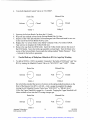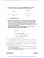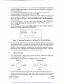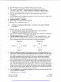
1
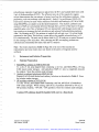
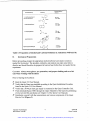
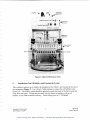
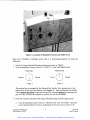
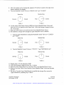
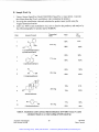
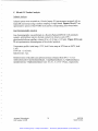
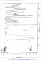
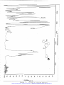
Artisan Technology Group is your source for quality
new and certified-used/pre-owned equipment
• FAST SHIPPING AND
DELIVERY
• TENS OF THOUSANDS OF
IN-STOCK ITEMS
• EQUIPMENT DEMOS
• HUNDREDS OF
MANUFACTURERS
SUPPORTED
• LEASING/MONTHLY
RENTALS
• ITAR CERTIFIED
SECURE ASSET SOLUTIONS
SERVICE CENTER REPAIRS
Experienced engineers and technicians on staff
at our full-service, in-house repair center
WE BUY USED EQUIPMENT
Sell your excess, underutilized, and idle used equipment
We also offer credit for buy-backs and trade-ins
www.artisantg.com/WeBuyEquipment
InstraView REMOTE INSPECTION
LOOKING FOR MORE INFORMATION?
Visit us on the web at www.artisantg.com for more
information on price quotations, drivers, technical
specifications, manuals, and documentation
SM
Remotely inspect equipment before purchasing with
our interactive website at www.instraview.com
Contact us: (888) 88-SOURCE | [email protected] | www.artisantg.com
ARGONAUT
TECHNOLOGIES
Quest 21 0: User Tutorial
R'OH or
Et
SLEt
H
PS-DES
(150 mg, ArgoCap)
A
R'
(6equiv
I
R~
7 mol% RhCI(PPh3)3
NMP (3 mL), 60°C, 3 h
1) 0.4 M HFIpyridine in THF (4 mL)
2) MeOSiMe3
(0.5 mL, 2 equiv. relative to
-
Figure 1. Synthesis of Resin Bound Ethers to Form the Corresponding Alcohol
The objective of the Quest 2 10 Organic Synthesizer Tutorial is to introduce and
familiarize new users to the instrument. The tutorial guides the user through instrument
operations using a synthesis as a training vehicle. The reaction scheme for the synthesis
is shown in Figure 1. All of the materials necessary for the Quest 21 0 User Tutorial are
listed in Table 1. Please allow for extra materials so there is plenty of reagent and
solvent available for performing the syntheses.
The tutorial is divided into the following sections, (I) Instrument and Solution
Preparation, (11) Coupling Reaction, (111) Addition of CleavageIScavenger and Product
Collection, (IV) Cleaning and Maintenance and Sample Work UpIAnalysis. The
experiment is performed in duplicate using a bank of ten reaction vessels (RVs) on the
Argonaut Technologies
Part Number 102298
04/02/98
Quest Tutorial
Artisan Technology Group - Quality Instrumentation ... Guaranteed | (888) 88-SOURCE | www.artisantg.com
Material
Source
ArgoCaps (PS-DES)
Argonaut
Comment
150 mg/capsule,
Wilkinson's catalyst
Chlorotris(triphenylphosphine)
rhodium(1) (RhC1(PPhj);
1-(2-methoxybenzoy1)-2
pGolidinemethanol
1-na~hthaleneethanol
2,2-diphenylethanol
Epiandrosterone
4-biphenylcarboxaldehyde
HFiwridine
.-
Strem
-0.68 mmollg*
FW 925.23
1 Aldrich
I FW 235.28
I
1 282 mg
I
I FW
1 206 mg-
Aldrich
Aldrich
Aldrich
Aldrich
Aldrich
Methoxytrimethylsilane (MeOSiMe;)
Aldrich
1-Methyl-2-pyrrolidinone, anhydrous
Aldrich
(NMP)
Aldrich
Fisher
Pyridine, anhydrous
Tetrahydrofuran,
anhydrous (THF)
Dichloromethane,
anhydrous (DCM)
I Total amount used
10 capsules supplied with
the Quest 2 10
76 mg
Fisher
172.23
FW 198.27
FW 290.45
FW 182.22
-70% HF,
-30% pyridine
FW 104.23,
d = 0.756
99.5% Dried over
molecular sieves
Sure-seal
HPLC grade
Stored under N2
HPLC grade
Stored under NZ
238 mg
348 mg
218 mg
0.4 mL
5.0 mL
220 mL
0.8 mL
210 mL
240 mL
* Due to lot differences in the PS-DES resin, the amount of solvents and reagents required for this tutorial may
be different from the amounts shown in Table 1. Refer to Figure 1 and the lot information supplied with the
PD-DES ArgoCaps to calculate the materials necessary for your synthesis.
Table 1. Solvents and Reagents Needed for the Quest 210 Tutorial
Quest 2 10 Synthesizer. Syntheses should be performed in the reaction vessels as shown
in Table 2. Polystyrene-Diethylsilane linker (PS-DES resin) encapsulated in
RV number
1,6
Diversity Reagent
1-(2-methoxybenzoy1)-2pyrrolidinemethanol
4, 9
epiandrosterone
Structure
~h'
L~~
Table 2. Quest 210 Tutorial Reaction Vessel Set Up
Argonaut Technologies
Part Number 102298
04/02/98
Quest Tutorial
Artisan Technology Group - Quality Instrumentation ... Guaranteed | (888) 88-SOURCE | www.artisantg.com
polycarbonate capsules (ArgoCaps) are placed into the RVs and washed three times with
4 mL of dichloromethane (DCM). The efficient removal of the capsule by organic
solvent demonstrates the convenience of using ArgoCaps for solid-phase synthesis. After
performing a solvent exchange with anhydrous 1-methyl-2-pyrrolidinone (NMP), PSDES resin is allowed to react with a selection of alcohols and carbonyls (0.3 M in NMP)
using R l ~ c l ( P P h as
~ ) catalyst
~
at an elevated temperature. The alcohol, carbonyls and
catalyst in NMP are conveniently delivered through the Luer Port of the Quest 21 0 upper
manifold under a low flow of nitrogen. RVs are pressurized with nitrogen to provide an
inert reaction environment for both alcoholysis and carbonyl hydrosilylation reactions.
After 3 h of heating at 60°C, the mixture is washed with solvent via a 4 L solvent bottle
connected to the Quest. This delivery system allows for parallel solvent delivery to 10
RVs simultaneously. The resin can be either dried for FT-IR analysis or carried forward
for the cleavage of the silyl ether. After cleavage and HF scavenging, products are
collected and concentrated for mass yield and GC analysis.
Note: The results reported in Table 4 (Page 28) at the end of this tutorial are
representative and your results may vary based on the purity of reagents used for
synthesis.
Instrument and Solution Preparation
Solution Preparation
RhCl(PPh3)3solution in NMP (0.0075 M)
) ~ mg,
To a dry ?imL pear-shaped flask containing a stir bar, add R l ~ c l ( P P h ~(76
0.082 rnrnol) under nitrogen. Add anhydrous NMP (1 1 mL) to completely dissolve
the catalyst. Store the solution under nitrogen.
Alcohol or carbon4 solution in NMP (0.3 M)
Prepare 4 mL of stock alcohol and carbonyl solutions as described in Table 3. Store
the solution under nitrogen.
HFIpvridine solution in THF (0.4 M)
To a dry 100 mL pear-shaped flask containing a stir bar, add 40 mL of anhydrous
THF under nitrogen. While stirring, add 0.8 mL of pyridine followed by 0.4 mL of
HFIpyridine (Aldrich, -70% HF, -30% pyridine). Store the solution under nitrogen.
Caution: HF solutions should be handled with care in a fume hood.
Argonaut Technologies
Part Number 102298
04/02/98
Quest Tutorial
Artisan Technology Group - Quality Instrumentation ... Guaranteed | (888) 88-SOURCE | www.artisantg.com
I
AlcohoVCarbonyl
AlcohollCarbonyl
Amount
Structure
1-naphthaleneethanol
2.2-diphenylethanol
1
206 mgl
4 rnL NMP
Ph
h
Ph
238 mgl
oH
4 rnL NMP
218 mgl
4 rnL NMP
I
Table 3. Preparation of Alcohol and Carbonyl Solutions in Anhydrous NMP (0.3 M)
B.
Instrument Preparation
Before proceeding, prepare the appropriate alcohol/carbonyl and catalyst solutions
needed for the tutorial. The alcohols, carbonyls, and catalyst may take some time to
dissolve and should therefore be prepared at least an hour before they are needed for the
experiment.
CAUTION:Always wear gloves, eye protection, and proper clothing such as a lab
coat when working with the Quest.
Prior to Starting the Synthesis:
Read the Quest 2 10 User Manual.
Verify that the Quest was installed according to the Quest Installation Procedure
found in the Quest 2 10 User Manual.
Verify that a 30-40 psi inert gas supply is connected to the Quest Controller Unit.
Flush tetrahydrohan (THF) through the Upper Manifold of the Quest by performing
several solvent fills and drains (see Chapter 3 of the Quest User Manual).
Familiarize yourself with the nomenclature and various components of the Quest
Reactor Unit (Figure 2).
Argonaut Technologies
Part Number 102298
04/02/98
Quest Tutorial
Artisan Technology Group - Quality Instrumentation ... Guaranteed | (888) 88-SOURCE | www.artisantg.com
Drain I
Figure 2. Quest 210 Reactor Unit
Installation of an Oil Bubbler and Purging the System
-
This synthesis requires an oil bubbler be installed in the Utility 1 port located at the top of
the instrument (Figure 3). Use 118 inch Teflon tubing to connect the oil bubbler to the
Quest 21 0. The bubbler outlet should be pointed towards the back of the fume hood and
away from the Quest. Fittings are provided with the Quest to interface with an oil
bubbler, or any other external accessory. These fittings have a !A"-28 thread.
Argonaut Technologies
Part Number 102298
04/02/98
Quest Tutorial
Artisan Technology Group - Quality Instrumentation ... Guaranteed | (888) 88-SOURCE | www.artisantg.com
Figure 3. Location of Manifold Controls and Utility Ports
Once the oil bubbler is installed, ensure that it is functioning properly by doing the
following:
1 Verify the Upper Manifold Membrane Pressure Switch is "OPEN".
2 Turn the Manifold Control Valves to "UTILITY 1" and "METERED GAS".
Drain Gas
Utility 1
Metered Gas
Utility 2
The metered gas is regulated by the Metered Gas Needle Valve located next to the
utility ports on the top of the Reactor Unit (Figure 3). Turn the Metered Gas Needle
Valve counter clockwise to increase the gas flow rate and clockwise to decrease the
gas flow rate. Observe the differences in flow rate via the oil bubbler.
3 Flush the common channels of the Upper Manifold using the following protocol:
a. Turn the Manifold Control Valves to "DRAIN GAS" and "CLOSED. Open the
Lower Manifold Drain Valves by pushing the levers down one at a time or by
Argonaut Technologies
Part Number 102298
04/02/98
Quest Tutorial
Artisan Technology Group - Quality Instrumentation ... Guaranteed | (888) 88-SOURCE | www.artisantg.com
using the white Teflon Drain Lever provided with the Quest to drain all I0 RVs in
parallel.
Drain Gas
Metered Gas
Utility 1
Utility 2
Leaving the Lower Manifold Drain Valves open, turn off the Drain Gas (set the
left valve to "CLOSED") and turn on the METERED GAS. Note- Do not turn
the Manifold Control Valves to "DRAIN GAS" and "METERED GAS"
simultaneously.
Drain Gas
Metered Gas
Utility 1
Utility 2
c. Turn both Manifold Control Valves to "CLOSED and close the Lower Manifold
Drain Valves by flipping the Drain Levers upward.
Drain Gas
Metered Gas
Utility 1
Utility 2
Remove the glass waste tank and dispose of the solvent waste. To remove the glass
waste tank, push the silver buttons on the handles of the collection tray (located
below the Lower Manifold of the Reactor Unit) and slowly slide the collection tray
down to its lowest position. Remove the waste tank and dispose of the waste in
accordance with local laws and regulations.
With an appropriate solvent, rinse the underside of the Lower Manifold where the
Teflon lines for fraction collection are located. It is recommended to use a volatile
solvent such as acetone. Carefully dry the area with a Kimwipe or laboratory towel
taking care not to bump or bend the Teflon collection lines.
To reinstall the glass waste tank, place the empty tank onto the collection tray and
slide the tray into position via the silver buttons located on the collection tray handles.
The silver buttons will snap out to verify that the waste tank is locked into position.
Argonaut Technologies
Part Number 102298
04/02/98
Quest Tutorial
Artisan Technology Group - Quality Instrumentation ... Guaranteed | (888) 88-SOURCE | www.artisantg.com
D.
RV Removal & Instrument Cleaning
1. To remove the RVs from Side A (RVs 1-10) use the following protocol.
a. Position the rotating lever on the right side of the Reactor Unit so that is sticking
out from the right side of the Quest parallel to the bench top. Rotate the lever in
towards the front of the Quest 2 10 Reactor Unit. Insert the rotating lever into the
slot in the blue handles of the Upper Manifold (early production Quest 2 10
Systems have two steel pins instead of the slot in the Upper Manifold handles).
b. While pushing the silver button in on the right Upper Manifold handle pull the
rotating lever up. Slide the right side of the Upper Manifold up as far as possible.
c. Slide the left side of the Upper Manifold up using the left rotating lever in the
same manor as the right side. This end should lift much easier now that the right
side of the Upper Manifold has been raised.
d. Push the silver buttons in on both Upper Manifold handles and slide the Upper
Manifold up until the silver buttons snap out indicating that the manifold is locked
into position.
2. Using the RV extraction tool (red pliers) supplied in the Quest starter kit, remove the
old RVs (RVs 1-10, Side A). To remove the RV, grasp the top of the RV (Figure 4)
Figure 4. Grasp the top of the RV with the RV extraction tool
Argonaut Technologies
Part Number 1022%
04/02/98
Quest Tutorial
Artisan Technology Group - Quality Instrumentation ... Guaranteed | (888) 88-SOURCE | www.artisantg.com
Figure 5. Using the RV mount as a fulcrum, twist the RV to "break it free"
from the Lower Drain Manifold male RV fitting
and "twist-up" using the RV holder as a fulcrum (Figure 5) to break the RV free of
the clamping ring (Figure 6). Take care not to bump the tube inserts which protrude
from the Upper Manifold male RV fittings.
Figure 6. The RV is Free from the Lower Drain Manifold male RV fitting.
Argonaut Technologies
Part Number 102298
04/02/98
Quest Tutorial
Artisan Technology Group - Quality Instrumentation ... Guaranteed | (888) 88-SOURCE | www.artisantg.com
Figure 7. Remove the RV from the holder
With your fingers, remove the RV from the Reactor Unit (Figure 7)
Using a sharp pair of scissors, cut the top of the RV off below the crimp from the RV
extraction tool.
Use the external hand magnet provided in the Quest starter kit to remove the magnet
mixers from the RV. Remove the magnets by sliding the magnets out through the top
of the RV.
Wash the magnetic mixers with an appropriate solvent such as acetone.
Remove the Luer Plugs (twist and pull) from the Upper Manifold, rinse them with an
appropriate solvent (e.g., acetone), and wipe clean.
Use a wash bottle or syringe to rinse the Luer Ports of the Upper Manifold with an
appropriate solvent. Hold a soft cloth or paper towel beneath the Upper Manifold to
absorb the rinse solvent.
Use a cotton swab wetted with an appropriate solvent to wipe the inside of the Luer
Ports of the Upper Manifold and to wipe around the Upper Manifold male Teflon RV
fittings.
10. Use a cotton swab wetted with an appropriate solvent to wipe clean the male Teflon
RV fittings of the Lower Drain Manifold. Lift the RV collars and wipe around the
bottom of the male Teflon RV fittings.
11. Finally, re-examine the Upper and Lower Manifold male RV fittings. Clean the RV
fittings and remove any residue or particulates with a soft cloth and an appropriate
solvent. Do not allow any particulates to enter the drain holes of the Lower Manifold
male RV fittings. Take care not to scratch the male RV fittings as this may result in
leaks.
Argonaut Technologies
Part Number 102298
04/02/98
Quest Tutorial
Artisan Technology Group - Quality Instrumentation ... Guaranteed | (888) 88-SOURCE | www.artisantg.com
RV Installation
Slide ten 5 mL RVs between the aluminum heating plate and spring loaded insulators
on the Reactor Unit. Press them down over the male Teflon RV fittings on the Lower
Drain Manifold. Do not attempt to fully seat the RVs at this time.
Place the Reaction Vessel Insertion Tool on top of the RV as shown in Figure 8.
Figure 8. Aligning the Reaction Vessel Insertion Tool with the RV
Press down on the RV with the RV Insertion Tool to seat the RV over the male
Teflon RV fitting of the Lower Drain Manifold (Figure 9).
Figure 9. Seating the RV with the RV Insertion Tool
Argonaut Technologies
Part Number 102298
11
04/02/98
Quest Tutorial
Artisan Technology Group - Quality Instrumentation ... Guaranteed | (888) 88-SOURCE | www.artisantg.com
4. Check that the vessels are fully seated over the male Teflon RV fittings of the Lower
Drain Manifold. If the vesseIs are seated properly, the tops of the vessels will be
horizontally uniform and the frits will be seated just above or on the male Teflon RV
fittings of the Lower Drain Manifold (Figure 10).
Figure 10. Proper installation of the Quest RVs
11.
Coupling Reaction
To a bank of ten RV's (e.g., RVs 1-10, Side A), an ArgoCap of PS-DES resin is added.
The capsule is dissolved by washing with DCM (3 x 4 ml, 5 min. agitation). After
dissolving the ArgoCap, a solvent exchange with anhydrous NMP (3 x 4 mL, 5 min.
agitation) is performed. Under nitrogen, the appropriate alcohol or carbonyl solution in
NMP (0.3 M, 2 mL, 0.6 rnmol) is added to each RV via syringe. To this mixture,
R l ~ c l ( P P h solution
~)~
in NMP (1 mL, 0.0075 M, 7.5 x lo4 rnmol) is added under
nitrogen. The mixture is agitated for 3 h at 60°C and then washed with NMP x 3, DCM x
3, and THF x 2 (4 mL, agitate 5 min.). You may stop here if you do not wish to perform
the resin cleavage/scavenge. Instead of analyzing the cleaved products by GC,
qualitative IR analysis may be performed on the loaded resin. To prepare the resin for
analysis, dry the resin and take an IR spectra of the beads to see if the coupling reaction
was complete. Ether formation can be monitored by looking for the disappearance of the
Si-H IR stretch at 21 00 cm-'.
A.
Addition of PS-DES ArgoCaps to the RVs
1 . Drop one 150 mg PS-DES ArgoCap into each 5 mL Teflon RV previously installed.
2. Move the agitator to the up position by pushing the Agitation UP button located to the
right of the Quest Controller Unit display (Figure 11).
Argonaut Technologies
Part Number 102298
04/02/98
Quest Tutorial
Artisan Technology Group - Quality Instrumentation ... Guaranteed | (888) 88-SOURCE | www.artisantg.com
Figure 11. Quest Controller Unit display
Place a single magnet mixer into each RV with the fin facing downward. Use the
external hand magnet found in the Quest starter kit to align the magnet mixers with
the magnetic agitation bar.
Lower the Upper Manifold onto the RVs by doing the following:
a. Push in the silver buttons on the blue handles of the Upper Manifold.
b. Using the Upper Manifold handles, slowly slide the Upper Manifold onto the tops
of the RVs. Do not push the male Teflon fittings of the Upper Manifold into
the RVs at this time.
c. Use the Rotating Levers on either side of the Quest to simultaneously lock both
sides of the Upper Manifold into place. First move the Levers so they stick out
from the sides of the Quest 210 Reactor Unit parallel to the bench top. Next,
rotate the levers towards the front of the Quest 2 10 Reactor Unit. Insert the levers
into the slot in the blue handles of the Upper Manifold. Push down on the
Rotating Levers and slide the Upper Manifold into the RVs. Keep pushing until
the silver buttons on the blue handles snap out indicating that the Upper Manifold
is locked into place.
Replace the Luer Plugs (push and twist) into the Luer Ports of the Upper Manifold.
Changing the 4 L Solvent Bottle
Ensure the Manifold Membrane Pressure Switch is in the "OPEN" position.
Vent the Upper Manifold by turning the Manifold Control Valves to "CLOSED" and
"VENT". Wait -5 seconds.
Drain Gas
Utility 1
Metered Gas
Utility 2
Vent the 4 L Solvent Bottle by turning the black valve on the Solvent Bottle Cap to
the "VENT" position and allow the solvent bottle to vent for -1 minute.
Argonaut Technologies
Part Number 102298
04/02/98
Quest Tutorial
Artisan Technology Group - Quality Instrumentation ... Guaranteed | (888) 88-SOURCE | www.artisantg.com
T m both Manifold Control Valves to "CLOSED"
Drain Gas
Solvent
Metered Gas
Closed
Vent
Utility 1
@-
Closed
Utility 2
Unscrew the Solvent Bottle Cap from the 4 L bottle.
Wipe off any residual solvent on the Solvent Bottle Pick-Up Line.
Dispose of the white polyethylene SolventIReagent Inlet Filter and install a new one
on the end of the Solvent Bottle Pick-Up Line.
Replace the 4 L solvent bottle in the Safety Container with a 4 L bottle of DCM.
Take care not to misplace the Teflon bottle seal.
Remove the cap from the DCM bottle. Insert the Teflon bottle seal into the neck of
the DCM bottle. Screw the bottle cap assembly on hand tight. Turn the black valve
on top of the Solvent Bottle Cap towards the tubing marked "Bottle Pressure". Wait
-1 minute for the bottle to pressurize.
Parallel Delivery of Methylene Chloride to RVs for ArgoCap Washing
To deliver DCM to 10 RVs in parallel, "pressurize" the bottle of DCM and "vent" the
RVs by turning the Manifold Control Valves to "SOLVENT" and "VENT". When
Drain Gas
Solvent
Metered Gas
Closed
Vent
Utility 1
0
Closed
Utility 2
the solvent has reached the top row of screws on the spring-loaded insulators on the
front of the Reactor Unit (RV is 314 fill, -4 mL), purge the manifold by slowly
turning the left Manifold Control Valve from "SOLVENT" to "DRAIN GAS".
Allow the Upper Manifold to purge for -5 seconds. Purging the Upper Manifold will
chase residual solvent into the RVs using nitrogen gas.
Drain Gas
Metered Gas
Vent
Utility 1
Argonaut Technologl~s
Part Number 102298
G
Closed
Utility 2
04/02/98
Quest Tutorial
Artisan Technology Group - Quality Instrumentation ... Guaranteed | (888) 88-SOURCE | www.artisantg.com
2. Close the Upper Manifold by first turning the left Manifold Control Valve to
"CLOSED", then turn the right Manifold Control Valve to "CLOSED".
D.
Drain Gas
Metered Gas
Utility 1
Utility 2
Adjusting the Agitation Bar
1. Ensure that the Agitator Bar is in the UP position (move the agitator up by pushing
the Agitation UP button located to the right of the Quest Controller Unit display).
2. Use the 7/64" hex wrench supplied with the Quest to loosen the Agitation Stops.
Adjust the Agitation Stops on the Reactor Unit so the maximum magnet height is -2
cm below the solvent level in the RVs. Tighten the Agitation Stops so both stops are
at the same height (see Figure 2).
3. On the Quest Controller Unit press the MODE soft key located below the LCD
display until the Agitation menu is displayed (Figure 12).
---- -----MixEvery
Upstroke
% Upward
-
-------:
:
:
4.0 sec
3.8 sec
95 %
- Not Agitating -
-
-
Figure 12. Agitation LCD Display
E.
Agitation Cycles for ArgoCap Washing
The following washing/agitation regimen is recommended for use with polystyrene resin
encapsulated ArgoCaps. The agitation is gradated in order to provide gentle agitation for
the initial dissolution of the ArgoCaps. Once the ArgoCaps have dissolved and the resin
is swollen in DCM solvent, the agitation is set for a gentle cycle to be used throughout
the synthesis. Please note that these Parameter Settings are representative and may vary
somewhat from instrument to instrument.
1. Press the Right or Left soft keys ),"(
to select the "Mix Every" parameter (agitation
frequency) on the Agitation menu.
2. Use the PARAMETER SETTING soft keys (?&) to increase or decrease the agitation
frequency to the following: Mix Every 4.0 sec.
Argonaut Technologies
Part Number 102298
04/02/98
Quest Tutorial
Artisan Technology Group - Quality Instrumentation ... Guaranteed | (888) 88-SOURCE | www.artisantg.com
Press the Right or Left soft keys),'(
to select the % Upward parameter (the amount
of time the agitation bar remains in the up most position expressed as a percentage of
the agitation frequency).
Use the PARAMETER SETTING soft keys (?&) to increase or decrease the
%Upward parameter to the following: %Upward= 95%.
Turn the agitation on by pushing the Agitation ON soft key located to the right of the
Quest Controller Unit display. If solvent is splashing up onto the Upper Manifold,
readjust the height of the agitation bar via the agitation stops so that the magnets are
lower in the RVs
Let the Quest agitate for 5 strokes. Then using the PARAMETER SETTING soft
keys (?$) begin decreasing the %Upward value by 1% per 5 strokes until the
%Upward= 90%.
Finally, decrease the % Upward from 90% to 60%. This is the agitation parameter
setting to be used during the synthesis (Figure 13).
-
sec
2 - 4 sec
4.0
%
Upward
60 %
- Not Agitating - -
-
----------------Figure 13. Agitation Parameters for the Quest 210 Tutorial Synthesis
Try using the Mix Speed Needle Valve located in the lower right hand corner of the
Quest Controller Unit. It is a good idea to experiment with this valve and understand
the effect it has on the agitation. Turning the valve to the right (clockwise) will
"Soften" or slow the agitation. Eventually the valve will close completely and the
agitation will stop. Turning the valve counterclockwise opens the valve. When the
valve is open completely the agitation is at its maximum speed.
ArgoCap Washing
Move the agitator up by pushing the Agitation UP soft key located to the right of the
Quest Controller Unit display.
Turn the Manifold Control Valves to "DRAIN GAS" and "CLOSED".
Drain Gas
Metered Gas
Utility 1
Utility 2
Use the white Teflon Drain Lever provided in the starter kit to drain all 10 RVs in
paraIle1. Slip the handle over a11 10 of the drain valves and pull the white lever down,
draining the 10 RVs into the Waste Tank. Allow the RVs to drain for -1 0 seconds.
Argonaut Technologies
Part Number 102298
04/02/98
Quest Tutorial
Artisan Technology Group - Quality Instrumentation ... Guaranteed | (888) 88-SOURCE | www.artisantg.com
Raise the handle so the Lower Manifold Drain Valves are closed.
Add -4 mL DCM to the RVs by turning the Manifold Control Valves to
"SOLVENT" and "VENT". When the delivery is complete, purge the Upper
Manifold by slowly turning the left Manifold Control Valve to "DRAIN GAS".
Close the Upper Manifold by turning both of the Manifold Control Valves to
"CLOSED".
Turn the agitation on by pushing the Agitation ON soft key located to the right side of
the Quest Controller Unit display.
Agitate the resin for -5 minutes.
Repeat steps 1-8 two more times using DCM.
10. ~ r & the
n RVS as described in steps 1-4.
G.
Addition of Anhydrous NMP Under a N2 Sweep via the Upper Manifold
Luer Ports
Purge the resin for -30 seconds with nitrogen
a. Turn the Manifold Control Valves to "DRAIN GAS" and "CLOSED".
b. Toggle the 10 Lower Manifold Drain Valves open.
Close the Lower Manifold Drain Valves and vent the Upper Manifold by turning the
Manifold Control Valves to "CLOSED" and "VENT".
Turn the Manifold Control Valves to "UTILITY 1" and "METERED GAS". This
provides a low flow nitrogen sweep of the RVs during the addition of anhydrous
NMP. Metered Gas will flow out of the Utility 1 port to the oil bubbler.
Drain Gas
Metered Gas
Utility 1
Utility 2
Adjust the Metered Gas Needle Valve located on the top of the Quest Reactor Unit
until you see a steady stream of gas bubbling through the oil bubbler when one of the
Luer Plugs is removed from the Upper Manifold. This will ensure the establishment
of an inert atmosphere when removing the Luer Plugs to add solvent or reagent.
Modify the gas flow by turning the Metered Gas Needle Valve counter clockwise
(left) to increase the gas flow rate and clockwise (right) to decrease the gas flow rate.
Add anhydrous NMP (-4 mL) to the RVs. Remove the Luer Plug from the first RV
Luer Port (twist and pull) and insert the syringe needle below the Teflon lines of the
male Teflon RV fittings (below the stream of Nz). Take care not to score the interior
surfaces of the Luer Port with the needle. Marring the surface can affect the sealing
of the Luer Port. After delivery, replace the Luer Plug (twist and push) and add NMP
to the remaining 9 RVs in the same manner as the first.
Turn the agitation on by pressing the Agitation ON soft key located to the right of the
Quest Controller Unit display.
Agitate the resin for -5 minutes.
Argonaut Technologies
Part Number 102298
04/02/98
Quest Tutorial
Artisan Technology Group - Quality Instrumentation ... Guaranteed | (888) 88-SOURCE | www.artisantg.com
8. Move the agitator up by pressing the Agitation UP soft key located to the right of the
Quest Controller Unit display.
9. Turn the Manifold Control Valves to "DRAIN GAS" and "CLOSED".
Drain Gas
Utility 1
Metered Gas
Utility 2
10. Use the white Teflon Drain Lever to OPEN the Lower Manifold Drain Valves and
drain all 10 RVs in parallel to the Waste Tank. Allow the nitrogen to purge the resin
for -30 seconds.
11. Raise the Teflon Drain Lever and close the Lower Manifold Drain Valves.
12. Re-establish a nitrogen flow through the Upper Manifold to the oil bubbler.
a. Vent the Upper Manifold by turning the Manifold Control Valves to "CLOSED"
and "VENT".
Drain Gas
Metered Gas
Utility 1
Utility 2
b. Turn the Manifold Control Valves to "UTILITY 1" and "METERED GAS".
Drain Gas
Utility 1
Metered Gas
Utility 2
13. Repeat steps 5- 10 with anhydrous NMP.
14. Allow the nitrogen to purge the resin for -1 minute.
15. Raise the white Teflon Drain Lever and close the Lower Manifold Drain Valves.
16. Remove the white Teflon Lever from the Lower Manifold Drain Valves and set aside
for later.
17. Be sure to Vent the Upper Manifold and re-establish the nitrogen flow across the
Upper Manifold by repeating step 12 above.
Argonaut Technologies
Part Number 1022%
04/02/98
Quest Tutorial
Artisan Technology Group - Quality Instrumentation ... Guaranteed | (888) 88-SOURCE | www.artisantg.com
H.
Addition of Reagent Under Nitrogen to the Reaction Vessels
1. Adjust the Metered Gas Needle Valve located on the top of the Quest Reactor Unit
until you see a steady stream of gas bubbling through the oil bubbler when one of the
Luer Plugs is removed from the Upper Manifold.
2. Using a syringe add the alcohol or carbonyl diversity reagent in NMP to each RV.
a. Remove the Luer Plug from the first RV Luer Port (twist and pull) and insert the
syringe needle below the Teflon lines of the male Teflon RV fitting. Take care
not to score the interior surfaces of the Luer Port with the needle. Marring the
surface can affect the sealing of the Luer Port.
b. Dispense 2 mL of (1-2-methoxybenzoy1)-2-pyrrolidinemethanolin NMP to the
first RV.
c. Replace the Luer Plug (twist and push) onto the Upper Manifold.
d. Add the appropriate alcohol or carbonyl solution in NMP to the remaining 9 RVs
in the same manner as the first as described in Table 3.
3. Using a syringe, add 1 mL of catalyst solution in NMP to each RV in the same
manner as the alcohol and carbonyl diversity reagent (steps 1 and 2a-2d above).
4. Blanket RVs with nitrogen by turning the left Manifold Control Valve to "CLOSED".
Then, turn the right Manifold Control Valve to "CLOSED.
Drain Gas
Metered Gas
Utility 1
Drain Gas
Utility 2
Metered Gas
Utility 1
Utility 2
5. Toggle the "Upper Manifold Membrane" switch to "CLOSED". Please refer to the
Quest User Manual for the function of the Upper Manifold Membrane Switch.
I.
Adjusting the Agitation Bar
1. Raise the Agitation Bar up by pushing the Agitation UP soft key located to the right
of the Quest Controller Unit display.
2. Use the 7/64" hex wrench supplied with the Quest to loosen the Agitation Stops.
Adjust the Agitation Stops on the Reactor Unit so the maximum magnet height is -2
cm below the solvent level in the RVs. Tighten the Agitation Stops so both stops are
at the same height.
Argonaut Technologies
Part Number 102298
04/02/98
Quest Tutorial
Artisan Technology Group - Quality Instrumentation ... Guaranteed | (888) 88-SOURCE | www.artisantg.com
On the Quest Controller Unit press the MODE soft key located below the LCD
display until the Agitation menu is displayed. Set parameters as follows: Mix Every
4.0 sec and %Upward= 60%.
Turn the agitation on by pushing the Agitation ON soft key located to the right of the
Quest Controller Unit display. If solvent is splashing up onto the Upper Manifold,
readjust the height of the agitation. The Mix Speed Needle Valve located on the front
of the Quest Controller Unit may also be used to soften or slow the agitation by
turning the valve clockwise.
Setting the Reaction Temperature and Time
Select the Set Temperature menu on the Quest Controller Unit by pressing the MODE
soft key located below the LCD display (Figure 14).
I
------------- A:
B:
- Set Temperature 60C
20C
RV Size
5mL
03:OO
00.00
-
ON
OFF
5mL
Figure 14. Set Temperature and time menu
Use the Right or Left +
(),
soft keys to move the cursor to line A: (representative of
Side A, RVs 1- 10).
Use the same soft keys to move the cursor across to the temperature parameter. Use
the PARAMETER SETTING (?$) soft keys to set the temperature to 60 "C.
Use the Right or Left soft keys (*),
to move the cursor to the time setting. Use a
and the PARAMETER SETTING (T&) soft
combination of the Right or Left),'(
keys to set the time to 03:OO (3 hours).
to move the cursor to the RV size settings. Use
Use the Right or Left soft keys),'(
the PARAMETER SETTING (?&) soft keys to select the 5 mL RV size.
Use the Right or Left),'(
soft keys to move the cursor to line A. Press the red and
blue STARTISTOP soft key located beneath the Quest LCD display to turn the
heaters on. The cursor must be on line A of the Set Temperature menu to activate the
heaters for Side A.
Select the Monitor Temperature display on the Quest Controller Unit by pressing the
MODE soft key (Figure 15).
When the heaters reach the programmed temperature, the timer will begin counting
down fiom 03:00:00 hours.
Argonaut Technologies
Part Number 102298
04/02/98
Quest Tutorial
Artisan Technology Group - Quality Instrumentation ... Guaranteed | (888) 88-SOURCE | www.artisantg.com
9. The heaters will shut off when the timer runs out and the RVs will begin cooling to
ambient temperature.
-----------------
A (ON)
SET
ACT
B (OFF)
60.0 20.0
60.9 1 6 - 2
02:59:35 0O:OO:OO
Figure 15. Temperature monitor display
K.
Draining the RVs
1. After the instrument has returned to room temperature (-30 min.), open the Upper
Manifold Membrane by following these steps:
a. Vent the Upper Manifold by turning the Manifold Control Valves to "CLOSED"
and "VENT".
b. Supply Metered Gas to the Upper Manifold before opening the Upper Manifold
Membrane by turning the Manifold Control Valves to "CLOSED" and
"METERED GAS".
c. Toggle the Upper Manifold Membrane Switch to "OPEN.
2. Move the agitator up by pushing the Agitation UP soft key located to the right of the
Quest Controller Unit display.
3. Drain all 10 RVs in parallel to the Waste Tank by turning the Manifold Control
Valves to "DRAIN GAS" and "CLOSED". Open the Lower Manifold Drain Valves
by pushing the Drain Levers down. Purge the resin with nitrogen for -1 0 seconds.
4. Close the Lower Manifold Drain Valves by flipping the Drain Levers upward.
L.
Washing the Resin with NMP
1. Change the 4 L bottle of DCM to a 4 L bottle of NMP by doing the following:
a. Vent the Upper Manifold by turning the Manifold Control Valves to "CLOSED"
and "VENT". Wait -5 seconds.
b. Vent the 4 L Solvent Bottle by turning the black valve on the Solvent Bottle Cap
to the "Vent" position. Allow the soIvent bottle line to vent for -1 minute.
c. Turn both Manifold Control Valves to "CLOSED".
d. Unscrew and remove the Solvent Bottle Cap from the 4 L DCM Solvent Bottle.
e. Wipe off any residual solvent from the Solvent Bottle Pick-Up Line.
f. Throw away the white polyethylene SolventIReagent Inlet Filter and install a new
one on the end of the Solvent Bottle Cap Pick-Up Line.
g. Replace the 4 L solvent bottle in the Safety Container with a 4 L bottle of NMP.
Argonaut Technologies
Part Number 102298
04/02/98
Quest Tutorial
Artisan Technology Group - Quality Instrumentation ... Guaranteed | (888) 88-SOURCE | www.artisantg.com
h. Install the bottle cap assembly onto the 4L bottle of NMP. Ensure the Teflon
bottle seal is placed in the bottleneck and tighten the bottle cap. Turn the black
dial on top of the Solvent Bottle Cap towards the tubing marked "Bottle
Pressure". Wait a -1 minute for the bottle to pressurize.
2. Fill the RVs with NMP by turning the Manifold Control Valves to "SOLVENT" and
"VENT". Once the RVs are 314 full, -4 mL, purge the Upper Manifold by slowly
turning the left Manifold Control Valve from "Solvent" to "DRAIN GAS".
3. Close the Upper Manifold by turning both of the Manifold Control Valves to
"CLOSED".
4. Adjust the Agitation Bar by doing the following:
a. Raise the Agitation Bar up by pushing the Agitation UP soft key located to the
right of the Quest Controller Unit display.
b. Use the 7/64" hex wrench supplied with the Quest to loosen the Agitation Stops.
Adjust the Agitation Stops on the Reactor Unit so the maximum magnet bar
height is -1 -2 cm below the solvent level in the RVs. Tighten the Agitation Stops
so both stops are at the same height.
c. On the Quest Controller Unit press the MODE soft key located below the LCD
display until the Agitation menu is displayed. Set the agitation parameters as
follows: Mix Every 4.Osec and %Upward= 60%.
5. Turn the agitation on by pushing the Agitation ON soft key located to the right of the
Quest Controller Unit display. If solvent is splashing onto the Upper Manifold,
readjust the height of the agitation. The Mix Speed needle valve located on the front
of the Quest Controller Unit may also be used to soften or slow the agitation by
turning the valve clockwise.
6. Agitate the resin for 5-1 0 minutes.
7. Move the agitator up by pushing the Agitation UP soft key located to the right of the
Quest Controller Unit display.
8. Drain all 10 RVs in parallel to the Waste Tank by turning the Manifold Control
Valves to "DRAIN GAS" and "CLOSED" and opening the Lower Manifold Drain
Valves. Allow nitrogen to purge the resin for -30 seconds.
9. Vent the Upper Manifold by turning the control valves to "Closed" and "Vent" and
wait -5 sec
10. Close the Lower Manifold Drain Valves by flipping the Drain Levers upward.
11. Repeat steps 2-9 above (except step #4) and perform a total of 2 x NMP, 4 x DCM,
and 2 x THF resin washes. Change the 4 L solvent bottle as necessary following step
1 above.
NOTE: This is a convenient place to stop the synthesis. Cleavage of the resin may be performed
the following day. The resin can be left under nitrogen after washing out all the reagents. To
store the resin under nitrogen turn the Manifold Control Valves to "METERED GAS" and
"CLOSED". Make sure the METERED GAS Needle Valve is open. You may qualitatively
analyze the resin by IR for ether formation (disappearance of the Si-H stretch at 21 00 CM-' is
a diagnostic wavelength). Alternatively you may continue to cleave the resin and analyze
compounds by quantitative GC analysis.
Argonaut Technologies
Part Number 102298
04/02/98
Quest Tutorial
Artisan Technology Group - Quality Instrumentation ... Guaranteed | (888) 88-SOURCE | www.artisantg.com
111.
CleavageIScavenger of the Resin and Product Collection
Cleavage solution (0.4 M HFIPyridine in THF, 4 mL) is added to the washed resin using
a syringe and the mixture agitated for 2 h at room temperature. HF scavenger
(Me;SiOMe, 0.5 mL) is added to each RVs via syringe and the mixture agitated at room
temperature for an additional 2 h. The solvent from each RV is collected into
10-preweighed scintillation vials. The resin is then washed twice with THF (3 mL, 5
min. agitation). The wash solvent is collected into the 10 scintillation vials used above.
The solvent is evaporated from the samples using a Savant SpeedVac (SpeedVac, 60 min,
no heating) and the products weighed to determine the mass yield. THF (1 ml) is added
to each scintillation vial and the solutions analyzed by GC for product purity.
Addition of Cleavage Solution to the RVs
Provide a low flow rate nitrogen sweep of the RVs during the addition of cleavage
solution (HFIPyridine in THF) by turning the Manifold Control Valves to
"UTILITY 1" and "METERED GAS". Gas will flow out of the Utility 1 port to
the oil bubbler.
Adjust the Metered Gas Needle Valve located on the top of the Quest Reactor
Unit until you see a steady stream of gas bubbling through the oil bubbler when
one of the Luer Plugs is removed from the Upper Manifold. This will ensure the
establishment of an inert atmosphere during the addition of solvent or reagent
through the Upper Manifold Addition Port. Modify the gas flow by turning the
Metered Gas Needle Valve counter clockwise (left) to increase the gas flow rate
and clockwise (right) to decrease the gas flow rate.
Remove the Luer Plug from the first RV Luer Port (twist and pull) and insert the
syringe needle below the Teflon lines of the male Teflon RV fitting (below the
stream of Nz).Dispense 4 mL of HFIPyridine solution in THF. Take care not to
score the interior surfaces of the Luer Port with the needle, as marring the surface
can affect the sealing of the Luer Port. After delivery, replace the Luer Plug
(twist and push) and add cleavage solution to the remaining 9 RVs.
During the cleavage, keep the RVs under a nitrogen blanket by first turning the
Manifold Control Valves to "CLOSED" and "METERED GAS" and then turning
both of the Manifold Control Valves to "CLOSED".
Adjust the Agitation Bar by doing the following:
Raise the Agitation Bar up by pushing the Agitation UP soft key located to the
right of the Quest Controller Unit display.
Use the 7/64" hex wrench supplied with the Quest to loosen the Agitation Stops.
Adjust the Agitation Stops on the Reactor Unit so the maximum magnet height is
-2 cm below the solvent level in the RVs. Tighten the Agitation Stops so both
stops are at the same height.
On the Quest Controller Unit press the MODE soft key located below the LCD
display until the Agitation menu is displayed. Set the agitation parameters as
follows: Mix Every 4.0sec. and %Upward= 60°h.
Argonaut Technologies
Part Number 102298
04/02/98
Quest Tutorial
Artisan Technology Group - Quality Instrumentation ... Guaranteed | (888) 88-SOURCE | www.artisantg.com
Turn the agitation on by pushing the Agitation ON soft key located to the right side of
the Quest Controller Unit display. If solvent is splashing up into the Upper Manifold,
readjust the height of the agitation. The Mix Speed Needle Valve located on the front
of the Quest Controller Unit may also be used to soften or slow the agitation by
turning the valve clockwise.
Agitate the resin in cleavage solution for 2 hours at room temperature.
Addition of Liquid HF Scavenger (Methoxytrimethylsilane) to RVs
After the resin has agitated in the cleavage solution for 2 hours at room temperature,
Move the agitator up by pushing the Agitation UP soft key located to the right of the
Quest Controller Unit display.
Provide a low flow rate nitrogen sweep of the RVs during the addition of cleavage
solution (HFPyridine in THF) by turning the Manifold Control Valves to "UTILITY
1" and "METERED GAS". Gas will flow out of the Utility 1 port to the oil bubbler
Add 0.5 mL of Me;SiOMe to all RVs. Remove the Luer Plug from the first RV Luer
Port (twist and pull) and insert the syringe needle below the Teflon lines of the male
Teflon RV fittings (below the stream of N2) and dispense 0.5 mL of Me3SiOMe
scavenger solution. Take care not to score the interior surfaces of the Luer Port with
the needle, as marring the surface can affect the sealing of the Luer Port. After
delivery, replace the Luer Plug (twist and push) and add scavenger to the remaining 9
RVs.
During the scavenge step, keep RVs under a nitrogen blanket by first turning the
Manifold Control Valves to "CLOSED" and "METERED GAS". Then turn both of
the Manifold Control Valves to "CLOSED".
Turn the agitator on by pushing the Agitation ON soft key located to the right side of
the Quest Controller Unit display. If solvent is splashing up into the Upper Manifold,
readjust the height of the agitation. The Mix Speed Needle Valve located on the front
of the Quest Controller Unit may also be used to soften or slow the agitation strokes
by turning the valve clockwise.
Agitate the resin in cleavage/scavenger solution for 2 hours at room temperature.
C.
Product Collection
1. Pre-weigh ten 20 mL scintillation vials and place them in the Quest Scintillation Vial
Collection Rack.
2. Remove the glass waste tank and dispose of the waste in accordance with all local
laws and regulations.
WARNING
- Always wear gloves, eye protection, and proper clothing such as a lab
coat when working with the Quest.
3. Rinse the bottom of the Lower Manifold Reactor Unit where the Teflon lines for
collection are located with THF and wipe clean.
4. Place the Scintillation Vial Rack under the Reactor Unit. Raise the collection tray to
its upper most position by first pushing in the silver buttons on the Waste Tray
handles and sliding the Waste Tray up until the tops of the scintillation vials touch the
Argonaut Technologies
Part Number 102298
24
04/02/98
Quest Tutorial
Artisan Technology Group - Quality Instrumentation ... Guaranteed | (888) 88-SOURCE | www.artisantg.com
bottom of the Lower Manifold. The silver buttons will snap out to verify that the
collection tray is locked into position.
5. Ensure that each Teflon collection line is inside its own scintillation vial and that the
two vent lines are clear of any vials.
6. Move the agitator up by pushing the Agitation UP soft key located to the right of the
Quest Controller Unit display.
7. Vent the Upper Manifold of the Quest to prepare for the controlled draining of the
RV contents into the scintillation vials.
a. Turn the Manifold Control Valves to "CLOSED and "VENT".
b. Close the Metered Gas Needle Valve by turning the valve clockwise (to the right).
c. Turn the Manifold Control Valves to "CLOSED" and "METERED GAS".
8. Collect the contents of the RVs into the scintillation vials by doing the following,
a. Open Lower Manifold Drain Valve for the first RV.
b. Slowly turn the Metered Gas Needle Valve counterclockwise (to the left) until the
RV begins to empty. Adjust the Metered Gas pressure to control the speed at
which the RV empties. Drain the contents of the RV slowly to prevent the
product from splashing.
c. After the first RV has emptied proceed to empty the other RVs individually, one
at a time following steps 7 and 8.
D.
Collection of THF Cleavage Washes
1. Using a syringe, deliver 3 mL THF to the RVs by doing the following:
a. Vent the Upper Manifold by turning the Manifold Control Valves to "CLOSED"
and "VENT".
b. Remove the Luer Plug from the first RV Luer Port (twist and pull) and insert the
syringe needle below the Teflon lines of the male Teflon RV fitting (below the
stream of Nz) and dispense 3 mL THF. Take care not to score the interior
surfaces of the Luer Port with the needle, as marring the surface can affect the
sealing of the Luer Port. After delivery, replace the Luer Plug (twist and push)
and add THF to the remaining 9 RVs.
c. Close the Upper Manifold by turning both Manifold Control Valves to
"CLOSED".
2. Adjust the Agitation Bar by doing the following,
a. Raise the Agitation Bar up by pushing the Agitation UP soft key located to the
right of the Quest Controller Unit display.
b. Use the 7/64" hex wrench supplied with the Quest to loosen the Agitation Stops.
Adjust the Agitation Stops on the Reactor Unit so the maximum magnet height is
2 cm below the solvent level in the RVs. Tighten the Agitation Stops so both
stops are at the same height.
Argonaut Technologies
Part Number 1022%
04/02/98
Quest Tutorial
Artisan Technology Group - Quality Instrumentation ... Guaranteed | (888) 88-SOURCE | www.artisantg.com
c. On the Quest Controller Unit press the MODE soft key located below the LCD
display until the Agitation menu is displayed. Set the agitation parameters as
follows: Mix Every 4.0sec. and %Upward= 60%.
3. Turn the agitator on by pushing the Agitation ON soft key located to the right of the
Quest Controller Unit display. If solvent is splashing up onto the Upper Manifold,
readjust the height of the agitation. The Mix Speed Needle Valve located on the front
of the Quest Controller Unit may also be used to soften or slow the agitation by
turning the valve clockwise.
4. Agitate the resin for 5 rnin. at room temperature.
5. Move the Agitator Bar up by pushing the Agitation UP soft key located to the right of
the Quest Controller Unit display.
6. Vent the Upper Manifold of the Quest to prepare for the controlled draining of the
RV into the scintillation vials by doing the following.
a. Turn the Manifold Control Valves to "CLOSED7' and "VENT".
b. Close the Metered Gas Needle Valve by turning the valve clockwise (to the right).
c. Turn the Manifold Control Valves to "CLOSED" and "METERED GAS".
7. Collect the contents of the RVs into the scintillation vials by doing the following,
a. Open the first Lower Manifold Drain Valve.
b. siowly turn the Metered Gas Needle Valve counterclockwise (to the left) until the
RV begins to empty. Adjust the Metered Gas Needle Valve to control the speed
at which the RV empties. Drain the contents of the RV slowly to prevent the
product from splashing.
c. After the first RV has emptied proceed to empty the other RVs individually, one
at a time following steps 6 and 7.
Repeat steps 1-7 above (except step 2).
Allow the RVs to purge with nitrogen for -5 minutes. You may purge the RVs for a
longer period of time and use the nitrogen flow to dry the resin.
Close the Lower Manifold Drain Valves.
Vent the Upper Manifold by turning the Manifold Control Valves to "CLOSED" and
"VENT".
Close the Upper Manifold by turning both of the Manifold Control Valves to
"CLOSED".
Remove the Scintillation Vial Collection Rack fiom the Quest Reactor Unit and set
the vials aside for sample work-up and analysis. Remove the tray by pushing in the
silver buttons located on the Waste Tray handles of the Quest and slowly slide the
collection rack down to its lowest position.
Argonaut Technologies
Part Number 102298
04/02/98
Quest Tutorial
Artisan Technology Group - Quality Instrumentation ... Guaranteed | (888) 88-SOURCE | www.artisantg.com
1V.
Cleaning the Quest (Maintenance) and Sample Work UpIAnalysis
To ensure the Quest 2 10 is ready for the next synthesis it is recommended to flush the
Upper Manifold, all delivery lines, Luer Plugs and the Lower Manifold with a solvent
compatible with the synthesis. Dispose of the solvent waste in accordance with local
laws and regulations.
Flushing the System
Place the empty glass waste tank under the Quest Reactor Unit. Move the tray to its
upper most position using the waste tray handles. The silver buttons will snap out to
verify the waste tank is locked into position.
Perform three solvent washes (solvent delivery, agitation, drain) on the RV Bank used
for the synthesis. Select a solvent that will dissolve any solids or other residues
generated during the synthesis, in this case THF. Depending on the type of chemistry
used, it may be desirable to run a pattern of solvents through this wash process. If a
pattern of solvents is run through the system, do at least three washes with each
solvent. It is recommended that a volatile solvent, such as acetone, be flushed
through the system last.
After the last solvent wash, let the system drain for a couple of minutes to flush
residual solvent out of the Upper Manifold.
Be sure to vent the Upper Manifold by turning the Manifold Control Valves to
"CLOSED" and "VENT".
Remove each Luer Plug and clean with the same solvent as in step 2.
Rinse out the Luer Ports with an appropriate solvent and wipe clean with a cotton
swab wetted with the same solvent as in step 2.
Replace the Luer Plugs.
Flush the Upper Manifold to waste using the following protocol,
a. Open the Lower Manifold Drain Valves.
b. Turn the Manifold Control Valves to "DRAIN GAS" and "CLOSED" and allow
the delivery pathway to purge for -1 minute.
c. With the drain valves still open, turn the left Manifold Control Valve to
"CLOSED" and turn the right Manifold Control Valve to "METERED GAS".
This will purge the other common delivery path of the Upper Manifold. Allow
the system to purge for -1minute.
Vent the Upper Manifold by turning the Manifold Control Valves to "CLOSED and
"VENT
10. Close the Upper Manifold by turning each of the Manifold Control Valves to
"CLOSED".
11. Close the Lower Manifold Drain Valves.
Argonaut Technologies
Part Number 102298
04/02/98
Quest Tutorial
Artisan Technology Group - Quality Instrumentation ... Guaranteed | (888) 88-SOURCE | www.artisantg.com
B. Sample Work Up
1. Using a Savant SpeedVac (Model SS620DDA SpeedVac or equivalent), evaporate
the solvent from the 20 mL scintillation vials containing the product.
2. Re-weigh the scintillation vials and calculate the product mass yields using the
weights determined earlier.
3. Add 5 mL THF to each scintillation vial, mix to dissolve the products, and analyze by
Gas Chromatography for product purity (Table 4).
Alcohol Product
Theoretical
Yield
Yield
GC
Purity
pyrrolidinemethanol
epiandrosterone
71%
18.5 rng
69%
Table 4. Alcoholysis and Carbonyl Hydrosilylation of PS-DES resin (% yield
calculated based on a resin loading of 0.68 mmolelg)
Argonaut Technologies
Part Number 102298
04102198
Quest Tutorial
Artisan Technology Group - Quality Instrumentation ... Guaranteed | (888) 88-SOURCE | www.artisantg.com
C. IR and GC Product Analysis
Infrared Analysis
Infrared spectra were recorded on a Nicolet Impact 41 0 spectrometer equipped with an
InspectIR microscope using a random sampling of single beads Figures 16 and 17 are
representative spectra of the PS-DES resin and the corresponding resin-bound ether.
Gas Chromatography Analysis
Gas chromatography was performed on a Hewlett-Packard 6890 GC with automatic
sampler, split/splitless injector, thermal conductivity detector, and a HP-5
phenylmethylsilicone capillary column (30 m x 0.32 mm x 0.25 pm). Figure 18 through
22 are representative chromatograms of the alcohol products.
Temperature profile: initial temp 175OC, hold 3 min, ramp at 20°C/min to 30O0C, hold
1 min.
Flow rate: 1.5 mllmin.
Injection size: 3 pL.
Retention times of alcohols and carbonyl products obtained from RVs 1-5 (1-(2methoxybenzoy1)-2-pyrrolidinemethanol, 1-naphthaleneethanol, 2,2-diphenylethanol,
epiandrosterone, 4-biphenylmethanol) were: 6.6,4.1,4.5, 8.9,4.9 min., respectively.
Argonaut Technologies
Part Number 102298
04/02/98
Quest Tutorial
Artisan Technology Group - Quality Instrumentation ... Guaranteed | (888) 88-SOURCE | www.artisantg.com
ame~r~usue~~o~
Figure 1 6 .
PS-DES Infrared S p e c t r a
Artisan Technology Group - Quality Instrumentation ... Guaranteed | (888) 88-SOURCE | www.artisantg.com
agUey1WSUEJ 1 %
F i g u r e 17.
PS-DES-OR Infrared S p e c t r a
Artisan Technology Group - Quality Instrumentation ... Guaranteed | (888) 88-SOURCE | www.artisantg.com
S o r r e d Ey
Xrrltiplier
Dilution
Totals
:
F i g u r e 18.-Ana2p5is of I-(2-methoxybenzoyl)-2-pyrr~lidinemethanol
Artisan Technology Group - Quality Instrumentation ... Guaranteed | (888) 88-SOURCE | www.artisantg.com
Artisan Technology Group - Quality Instrumentation ... Guaranteed | (888) 88-SOURCE | www.artisantg.com
=========----======================================-----=============
Injection Dzte : 1/22/98 8 : 2 1 : 5 3 PM
S e q . Line : 13
Sample N a n e
A-cq. Operator
. .
:
Vial
Inj
- Volume
. -Actxtl I n j Volume
D I E T P I~n~
j volume
~ ~
frm S2qezCe !
Sequeaco File
: c :\E=CI-X\~\SEQ~'ENE\WSC~V.
s
Methcs
:
:
Inj :
rin
98
1
I pI
:
: 3
p1
C:\F>~Z-IY\Z\L~TT.IODS\JPSS.M
LZSC ~ h a , ~ ~ : ~1 0d/ 8 / 5 7 6 : 0 9 : 2 2
f OE-3 S phe,lylbuteze mezkce
PY by Trzcy
I
Figure 20.
'
Analysis of 2,2-diphenylethanol
Artisan Technology Group - Quality Instrumentation ... Guaranteed | (888) 88-SOURCE | www.artisantg.com
Vial- :
Fisure 21.
Analysis of
99
pia and roster one
Artisan Technology Group - Quality Instrumentation ... Guaranteed | (888) 88-SOURCE | www.artisantg.com
Figure 2 2 .
Analysis of 4 - b i p h ~ n v l m e t h a n o l
Artisan Technology Group - Quality Instrumentation ... Guaranteed | (888) 88-SOURCE | www.artisantg.com
Artisan Technology Group is your source for quality
new and certified-used/pre-owned equipment
• FAST SHIPPING AND
DELIVERY
• TENS OF THOUSANDS OF
IN-STOCK ITEMS
• EQUIPMENT DEMOS
• HUNDREDS OF
MANUFACTURERS
SUPPORTED
• LEASING/MONTHLY
RENTALS
• ITAR CERTIFIED
SECURE ASSET SOLUTIONS
SERVICE CENTER REPAIRS
Experienced engineers and technicians on staff
at our full-service, in-house repair center
WE BUY USED EQUIPMENT
Sell your excess, underutilized, and idle used equipment
We also offer credit for buy-backs and trade-ins
www.artisantg.com/WeBuyEquipment
InstraView REMOTE INSPECTION
LOOKING FOR MORE INFORMATION?
Visit us on the web at www.artisantg.com for more
information on price quotations, drivers, technical
specifications, manuals, and documentation
SM
Remotely inspect equipment before purchasing with
our interactive website at www.instraview.com
Contact us: (888) 88-SOURCE | [email protected] | www.artisantg.com