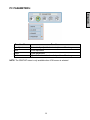
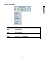
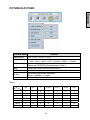
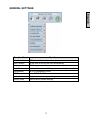
1
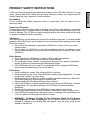
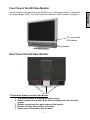
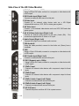
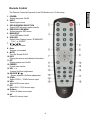
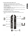
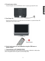
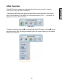
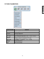
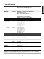
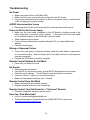
37” HD VIDEO MONITOR Model LVM-37w1 Contents INSTALLATION Package Contents……………………………….……………………. 4 Front View of the HD Video Monitor……………..………………….. 5 Rear View of the HD Video Monitor……………….………..………. 5 Side View of the HD Video Monitor…..……………………...……… 6 Remote Control…………………..…………………………..……….. 8 Installation………….…………………………………………………. 9 OSD Functions PICTURE PARAMETERS: Brightness / Contrast / Saturation / Hue / Color Temp / Sharpness / Aspect Ratio / Backlight / Reset……………………..…. 13 PC PARAMETERS: Auto Adjust / Clock / Phase / Position………..…..14 AUDIO SETTINGS: Volume / Bass / Treble / Balance / Mute / Speaker / Reset…………………...……………....….…... 15 PICTURE-IN-PICTURE: Display Mode / Main Source / PIP Source / Swap / PIP Position / PIP Size / Audio From.. 16 GENERAL SETTINGS: Menu Position / Menu Timeout / Language / Sleep Timer / Transparency / DPMS / System Info / Factory Reset………...….…... 17 Specifications………………………………………….…………….. 18 Troubleshooting ………………..………………………………….... 19 English Product Safety Instructions …………………..….………….………. 1 Safety Guidelines…………………………………………….……..… 2 Cleaning the HD Video Monitor………………..……………….…… 3 PRODUCT SAFETY INSTRUCTIONS Overloading Do not overload wall outlets, extension cords, or power strips. This can result in fire or electronic shock. Power Cord Protection Power supply cords should be routed so that they are not likely to be walked on or pinched by items placed upon or against them. Periodically inspect the cords and each end of the cords for damage. The HD Monitor shall be installed near a wall socket outlet and the plug on power cord shall be readily accessible. Ventilation Slots and openings on the cabinet are provided for ventilation purposes. To ensure reliable operation of the HD Monitor and to protect it from overheating, these openings must not be blocked or covered. • Do not block the openings by placing the HD Monitor on a bed, sofa, rug or other similar surface. • Do not place the HD Monitor in a built-in installation such as a bookcase or rack unless proper ventilation is provided and the manufacturer’s instruction have been adhered to. Other Notices • Avoid exposing the HD Monitor to direct sunlight or high temperatures. • Avoid exposing the HD Monitor to moisture or high humidity. • Do not attempt repairs yourself. Your warranty does not cover repairs or attempted repairs by anyone not authorized by Westinghouse Digital. • If the HD Monitor will not be used for a long period of time, unplug the HD Monitor and remove the batteries from the remote control. Precautions • Avoid touching the screen. Skin oils are difficult to remove. • Never remove the rear cover. The HD Monitor contains high-voltage parts. You may be seriously injured if you touch them. • Avoid exposing the HD Monitor to direct sunlight or another heat source. Orient the HD Monitor away from direct sunlight to reduce glare. • Always handle the HD display with care when moving it. • Place the HD Monitor in a well-ventilated area; don’t place the HD Monitor in airtight compartments. Do not place anything on the HD Monitor that prevents heat dissipation. • Ensure that the area around the HD Monitor is clean and free of moisture. • Do not place heavy objects on the HD Monitor, audio/video cables, or power cord. • If the HD Monitor emits smoke, abnormal noise, or a strange odor, immediately turn it off and contact the Westinghouse Service Center. • WARNING – To Reduce The Risk Of Fire Or Electric Shock, Do Not Expose The HD Monitor To Rain Or Moisture! The HD Monitor shall not be exposed to dripping or splashing and objects filled with liquids, such as vases, shall not be placed on the Monitor. 1 English Follow and obey all warnings and instructions marked on the HD Video Monitor. For your safety, please read all the safety and operating instructions before you operate the HD Monitor Keep this user’s manual for future reference. Safety Guidelines IMPORTANT NOTICE CONCERNING POWER CORD SELECTION The specific power cord for this HD Monitor is enclosed and has been selected according to the country of destination and must be used to prevent electric shock. Use the following guidelines if it is necessary to replace the original cord set, or if the cord set is not enclosed. The female receptacle of the cord set must meet IEC-60320 requirements and should look like Figure A1 below: Figure A1 Figure A2 For the United States and Canada In the United States and Canada the male plug is a NEMA5-15 style (Figure A2), UL Listed, and CSA Labeled. For LCD Monitors that are placed on a desk or table, type SVT or SJT cord sets may be used. For LCD Monitors placed directly on the floor, only SJT type cord sets may be used. The cord set must be selected according to the current rating for the LCD Monitor. Please consult the table below for the selection criteria for power cords used in the United States and Canada. Cord Type Size of Conductors in Cord Maximum Current Rating of Unit SJT SVT 18 AWG 16 AWG 14 AWG 18 AWG 17 AWG 10 Amps 12 Amps 12 Amps 10 Amps 12 Amps FCC Compliance Statement This equipment has been tested and complies with the limits for a Class B digital device, pursuant to part 15 of the FCC Rules. These limits are designed to provide reasonable protection against harmful interference in a residential installation. This equipment generates, uses, and can radiate radio frequency energy, and may cause harmful interference to radio communications if not installed and used in accordance with the instructions. However, there is no guarantee that interference will not occur in a particular installation. If this equipment does cause harmful interference to radio or television reception, which can be determined by turning the equipment off and on, the user is encouraged to try to correct the interference by one or more of the following measures: • • • • Reorient or relocate the receiving antenna. Increase the separation between the LCD Monitor and receiver. Connect the equipment into an outlet on a circuit different from that to which the receiver is connected. Consult the Westinghouse Service Center or an experienced radio/Monitor technician for assistance. FCC Warning To assure continued FCC compliance, the user must use a grounded power supply cord and the provided shielded video interface cable with bonded ferrite cores. If a BNC cable is used, use only a shielded BNC (5) cable. Also, any unauthorized changes or modifications not expressly approved by Westinghouse Digital will void the user's authority to operate this device. 2 English CAUTION: The power supply outlet should be located near the HD Monitor and should be easily accessible. Always use the appropriate AC cord that is certified for your specific country. Some examples are listed below: USA..................UL Switzerland ..... SEV Canada.............CSA Britain ............. BASE/BS Germany..........VDE Japan ............... Electric Appliance Control Act Cleaning the HD Video Monitor MAKE SURE THE HD Monitor IS TURNED OFF NEVER SPRAY OR POUR ANY LIQUID DIRECTLY ONTO THE SCREEN OR CASE To clean the screen: 1. Wipe the screen with a clean, soft, lint-free cloth. This removes dust and other particles. 2. If it still is not clean, apply a small amount of non-ammonia, non-alcohol based glass cleaner onto a clean, soft, lint-free cloth, and wipe the screen. To clean the case: 1. Use a soft, dry cloth. 2. If it still is not clean, apply a small amount of non-ammonia, non-alcohol based, mild nonabrasive detergent onto a clean, soft, lint-free cloth, then wipe the surface. Disclaimer Westinghouse Digital does not recommend the use of any ammonia or alcohol-based cleaners on the HD Monitor screen or case. Some chemical cleaners have been reported to damage the screen and/or HD Monitor case. Westinghouse Digital will not be liable for damage resulting from the use of any ammonia or alcohol-based cleaners. 3 English • • INSTALLATION Your product package includes: • 37” Westinghouse HD Video Monitor • Remote Control (with batteries) • Power Cord • Quick Connect Guide • User’s Manual • Component Video Cable (Green, Blue, Red) • Audio Cable (Red, White) 4 English Package Contents Front View of the HD Video Monitor “IR” receiver and LED indicator Speakers Rear View of the HD Video Monitor Screws To Detach the Speaker from the Video Monitor 1. Turn off the monitor and unplug the power supply. 2. Detach red and black speaker wires from the monitor first, then from the speaker. 3. Remove screws from the upper corners of the speaker. 4. Remove 4 screws from the back of the base. 5. Gently remove the speaker from the base. 5 English Use the buttons on the right side of the HD Monitor or on the remote control to display the On Screen Display (OSD). The OSD controls are defined in “OSD Functions” on page 12. Side View of the HD Video Monitor English 1. Menu Turn OSD Menu ON/OFF 2. Volume + / - Increase/Decrease sound volume or adjust a highlighted control while in the OSD Menu. 3. OSD Selection T/S Highlight a control while in the OSD Menu. 4. Input Select Active Video Input or choose a selection while in the OSD MENU. 5. Power Button Turn Power ON/OFF 6 Side View of the HD Video Monitor 2. DVI2 Audio Input (Right / Left) Connect an external audio source to this jack. 3. S-Video Input Connect to an external video device such as a HD Digital cable/satellite receiver, VCR, DVD or video game system. 4. AV Video Input Connect to an external video device such as a VCR, DVD and video game system. 5. AV & S-Video Audio Input (Right / Left) Connect an external audio source to this jack; (Audio (R/L). This connection supports either S-Video or AV input. 6. Audio Output (Right / Left) Connect this output to an external audio receiver. 7. VGA Audio IN Using the cable provided, connect to the Audio out (Green) from a computer. 8. VGA Using a 15-pin VGA cable, connect to a computer or other device with a VGA output. 9. DVI1 Audio Input (Right / Left) Connect an external audio source to this jack. 10. DVI1 (Supports up to 1080p) Using a 20-pin DVI cable, connect to a computer or other device with a DVI output. 11. YPbPr1 Input Connect an external video device with component output to these jacks. 12. YPbPr2 Input Connect an external video device with component output to these jacks. 13. YPbPr1 Audio 1 Input (Left / Right) Connect an external audio source to this jack. 14. YPbPr2 Audio 2 Input (Left / Right) Connect an external audio source to this jack. 15. AC IN (Power) Connect the power cord from AC IN to a power source. 7 English 1. DVI2 (Supports up to 1080i) Using a 20-pin DVI cable, connect to a computer or other device with a DVI output. Remote Control The Remote Control will transmit to the HD Monitor up to 10 feet away. English 1. POWER: Switch the power On/Off 2. INPUT Select input source 3. OSD SUB-MENU SELECTION Select OSD sub-menu option directly 4. PREVIOUS OSD MENU Select previous OSD menu 5. MENU/EXIT Turn OSD Menu On/Off. 6. SCALING Select Video Display format “STANDARD”, “FILL”, or “ZOOM” 7. T / S / W / X OSD MENU control 8. Enter Execute a command 9. MUTE Turn the Sound On/Off 10. INFO Display the source and channel information 11. PIP Display sub-picture On/Off 12. FREEZE Freeze main screen 13. VOL - / + Volume Up/Down adjustment 14. SOURCE T / S Source selection Up/Down adjustment 15. YPbPr Select YPbPr1 / YPbPr2 source input 16. VGA Select VGA source input 17. DVI Select DVI1 / DVI2 source input 18. S-Video Select S-Video source input 19. AV Select AV source input 8 Installation 1. Insert Remote Control Batteries 3) Re-attach the battery cover. CAUTION: • Only use AAA batteries. • Do not mix new and old batteries. This may result in cracking or leakage, which may pose a fire risk or lead to personal injury. • Insert batteries according to (+) and (−) markings. Inserting the batteries incorrectly may result in cracking or leakage, which may pose a fire risk or lead to personal injury. • Dispose of used batteries in accordance with local laws and regulations. • Keep batteries away from children and pets. • When the remote control will not to be used for an extended period, remove the batteries. 9 English 1) Remove the battery cover. 2) Insert the batteries corresponding to the (+) and (−) marks on the battery compartment. 2. Connect audio and video cables to a PC Connect one or all of the following into the back of the HD Monitor VGA CONNECTION: Connect an analog VGA cable from your PC VGA OUT port to the HD Monitor VGA IN port. DVI1/DVI2 CONNECTION: Connect a Digital DVI cable from your PC or DVD DVI OUT port to the HD Monitor DVI-HDCP port. AUDIO CONNECTION: Connect a stereo mini cable from the PC’s AUDIO OUT port to the AUDIO IN port on the HD Monitor. 3. Connect AV, Component, S-Video to Video Devices Connect Video/Audio cables from compatible devices to the back panel of the HD Monitor. 10 English IMPORTANT: Before beginning, make sure all devices are turned off. 4. Connect power cables Connect the power cord to the HD Monitor then to a properly grounded AC outlet. English 5. Turn Power On Press the Power ON button on the right side of the HD Monitor, or press the Power ON (Red) button on the remote control. 6. Select input source for the HD Monitor using the OSD menu or remote control 7. If connecting to a PC (VGA/DVI1/DVI2): For the best picture quality, set the HD Monitor timing mode to VESA1920 x 1080 at 60Hz (refer to the graphic card’s user guide to set this timing mode). 11 OSD Function To display the OSD main menu, press the Menu button on the right side of front control keys of the HD Monitor or the MENU key on the remote control. Use 3/4 arrow keys to highlight the desired OSD sub-menu. Main Menu To select a sub-menu, press ▲/▼ on the right side of the HD Monitor or the ▲/▼ key on the remote control. Also, by using the number keys on the remote control, you can select a OSD sub-menu directly. 12 English All the OSD function settings are controlled either by the remote control or using the control keys on the right side of HD Monitor. PICTURE PARAMETERS: English Function Name Brightness Contrast Saturation Hue Color Temp Function Aspect Ratio Brightness adjustment Contrast adjustment Saturation adjustment Hue adjustment Color temperature adjustment (Color 1, Color 2, Color 3) Sharpness adjustment (Sharpness cannot be adjusted in PC mode) Set display to “STANDARD” / “FILL” / “ZOOM” Backlight Backlight adjustment Reset Reset video settings Sharpness 13 PC PARAMETERS: English Function Name Auto Adjust Clock Phase Position Function Automatically adjust the horizontal phase of the image Clock adjustment Phase adjustment Adjust the horizontal and vertical position of the image NOTE: The GRAPHIC menu is only available when VGA source is selected. 14 AUDIO SETTINGS: English Function Name Volume Bass Treble Balance Mute Speaker Reset Function Volume adjustment Bass adjustment Treble adjustment Balance adjustment Select Audio OFF or ON Select internal or external speaker Reset audio settings 15 PICTURE-IN-PICTURE: English Function Name Display Mode Main Source Function OFF --> PIP --> PBP --> POP Select main screen sources VGA --> DVI1--> DVI2 --> AV --> S-Video--> YPbPr1 --> YPbPr2 PIP Source Select sub screen sources Please see PIP/PBP/POP specification in Table 1 Swap main screen and sub-screen source Swap PIP Position Sub-screen display horizontal/vertical position adjustment Sub-screen display size adjustment (Small -->Medium --> Large) Select main screen or sub-screen audio sources PIP Size Audio From Table 1: SUB VGA DVI1 AV S-Video YPbPr1 YPbPr2 DVI2 VGA X O O O X X O DVI1 O X O O O O O AV O O X X O O O S-Video O O X X O O O YPbPr1 X O O O X X O YPbPr2 X O O O X X O DVI2 O O O O O O X Main 16 GENERAL SETTINGS: English Function Name Menu Position Menu Timeout Language Sleep Timer Transparency DPMS System Info Factory Reset Function OSD horizontal/vertical position adjustment Set the time to turn off the OSD automatically OSD language selection Set sleep timer to turn off the power automatically Set OSD transparency level Select DPMS On/Off Display Input source, type and signal Restore factory default settings 17 Specifications Type 37" (37.07" viewable diagonal area), TFT (Thin Film Transistor), Active Matrix WXGA LCD, 1920*1080 vertical stripe Color Anti-reflective coating + Anti-glare coating 176° (H) / 176° (V) Viewing Angles Output Signal RGB Analog * 1 (75 ohms, 0.7 Vp-p)/Mini-Stereo *1 H/V separated (TTL) for PC DVI-D * 2 (HDCP support) / RCA (L/R) * 2 (DVI1 supports up to 1080P, DVI2 supports up to 1080i) fh: 30-80 kHz, fv: 50-75 Hz Component Video * 2 / RCA (L/R) Stereo * 2 Composite * 1 / S–Video * 1 / RCA (L/R) stereo * 1 RCA (L/R) Stereo * 1 HDTV Compatibility 480i, 480P, 720P, 1080i Input Signal PC Compatible Video/Audio Supported 1280 x 1024 @ 60, 75 Hz Supported 1280 x 768 @ 60, 75Hz 1024 x 768 @ 60, 75 Hz 800 x 600 @ 60, 75 Hz 640 x 480 @ 60, 75 Hz 720 x 400 @ 70 Hz 1280 x 1024 @ 60Hz Voltage 1280 x 768 @ 60, 75Hz 1024 x 768 @ 60, 75 Hz 800 x 600 @ 60, 75 Hz 640 x 480 @ 60, 75 Hz 720 x 400 @ 70 Hz 20W (x2 Channels) 100-240 VAC, 50/60 Hz (auto switch), 2.7A (MAX) (VGA & DVI1) (DVI2) Speaker Output Power Operating Conditions Temperature Humidity Altitude 1920 x 1080 @ 60 Hz 0° C to + 35° C (32° F to + 95° F) 10% to 90% (no condensation) To 3,000 m Temperature -20° C to + 60° C (-4° F to + 140° F) Humidity 10% to 90% (no condensation) Altitude To 12,000m Dimensions Physical 930 mm (W) x 720 mm (H) x 212 mm (D) Weight Net / Gross 52.9 lb (24.0kgs) / 69.4 lb (31.5kgs) Storage Conditions FCC-B, UL/c-UL Regulations Power On (Normal) 270W (Blue LED) Power Off <2W Power Saving <3W (Amber LED) Preset Timing Mode (Pre-adjusted to reduce blanking: 1920x1080 at 60Hz) Warning: Do not set the graphics card in your computer to exceed these refresh rates; doing so may result in permanent damage to the HD Monitor. Note: Product Specifications are subject to change without notice. 18 English Panel Troubleshooting No Power Make sure power button is ON (Blue LED). Make sure AC power cord is securely connected to the AC socket. Plug another electrical device (such as a radio) to the power outlet to verify that the outlet is supplying the proper voltage. AUDIO Interconnection Issues • Remember that S-Video and Composite (AV) share the same audio source. Power is ON but No Screen Image • • • • Make sure the video cable connected to the HD Monitor is tightly secured to the video output port on the back of the computer. If the other end of the video cable is not attached properly to the HD Monitor, secure it tightly. Adjust brightness and contrast. If you are using a Macintosh computer older than G3, you need a Macintosh adapter. Check Source settings. Wrong or Abnormal Colors • • If any colors (red, green, or blue) are missing, check the video cable to make sure it is connected securely. Loose or broken pins in the cable connector could cause an improper connection. Connect the HD Monitor to another computer. Remote Control Buttons Do Not Work • Press only one button at a time. No Sound • • • • • Check the audio connection. Press MUTE on the remote control, so that MUTE disappears from the screen. Check the audio settings. The HD Monitor audio may be set to minimum. Press the Volume + (Up) key on the remote control. Make sure the speaker setting is set to “internal”. Remote Control Does Not Work • • Make sure batteries are inserted correctly. Replace batteries with new ones if necessary. Remote Control Code Not Found in a “Universal” Remote • Purchase a separate “learning” remote control. How Can I Find More Help? • • Log on to: www.westinghousedigital.com Contact Westinghouse Customer Service at (866) 287-5555 or write us at [email protected] 19 English • • • SE-UM-3701-0501