1
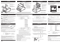
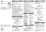
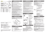
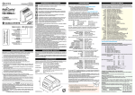
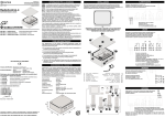
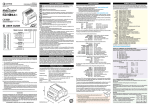
CARE AND MAINTENANCE
INPUTS / OUTPUT
Do not install this unit near medical devices like pacemakers or hearing
aids. This unit may interfere with the operation of these devices.
Your ATT-81 is the product of advanced engineering, design and craftmanship and
should be treated with care. The suggestion below will help you to enjoy this product
for many years.
Switch off this unit when flying.
Secure it so that it cannot be switched on inadvertently.
¡ Do not expose the unit to any extreme environment where the temperature or
humidity are out of operating range.
INPUTS
Eight digital inputs coming from SPST contacts can be wired to terminals 7-14.
Common return for contacts at terminal 6.
Using electronic switches, terminal 6 is the positive leg.
In order to avoid false triggering, contacts will be considered closed or open after
3 seconds from stable condition.
Modifying the configuration by means of GsmSuite, either in local or remote mode
it will be possible to change:
SAFETY INFORMATION
2CSM443004D9901
i
ATT-81
GSM/GPRS REMOTE MONITOR
Do not install this unit near petrol stations, fuel depots, chemical plants or
blasting operations when this unit can disturb the operation of technical
equipment.
T1
OU
IN
IN
IN
8
IN
9
2
IN
/dc
V ac
x:12
au
8
IN
1
10
7
6
5
4
C+
11
12
3
2
1
13
14
+
T
OU
7
4
3
1
3
4
1
T-8 5 IN 8
AT 6 IN 7
IN
6
5
2
USER GUIDE
2CSM381000R1371
2CSM208355R1371
Interference can occur if this unit is used near televisions, radios or
personal computers.
M
GS rk
wo
net
1
ATT-81 EMBEDDED ANTENNA
ATT-81E EXTERNAL ANTENNA
If the device has been stored in a cold environment, then condensation can
occur. Before starting operations, the device must be absolutely dry.
Thus, an acclimatization period of at least three hours must be observed.
r
In order to avoid possible damage, we recommend that you only use the
specified accessories.
These have been tested and shown to work well with this unit.
This device should be installed only by qualified personnel. Carefully read the
instruction manual in its entirety and keep it safe for future reference.
It is essential to know the information and comply with the instructions given in the
manual to ensure the fitting is installed, used and serviced correctly and safely.
This RF unit is not designed for and intended to be used in portable applications
(within 20 cm or 8 inches of the body of the user) and such uses are strictly prohibited.
¡ Do not use or store the unit in dusty or dirty areas. Its moving parts (SIM holder for
example) can be damaged.
¡ Do not use chemical cleaning agent on the unit or the SIM card.
¡ Do not attempt to disassemble the unit or remove any part or label.
There are no user serviceable parts inside.
¡ Do not abuse the unit by dropping, knocking or violenty shaking it.
Rough handling can damage it.
¡ Do not place the unit alongside computer discs, credit or travel cards or other
magnetic media. The information contained on these devices may be affected.
¡ This unit is under your responsibility. Please treat it with care respecting all local
regulations. It is not a toy. Therefore, keep it in a safe place at all times and out of
the reach of children.
¡ Try to remember your unlock and PIN codes. Become familiar with and use the
security features to block unautorised use and theft.
Both fixed and mobile applications are allowed, as defined below:
If incorrectly installed in a vehicle, the operation of GSM device could interfere with
the correct functioning of vehicle electronics. Verification of the protection of vehicle
electronics should form a part of the installation.
Regulations must be considered to operate a vehicle’s light or horn on public roads.
Mobile means that the device is designed to be used in other than fixed locations
and generally in such a way that a separation distance of at least 20 cm (8 inches)
is normally maintained between the transmitter’s antenna and the body of the user
or nearby persons.
All units are 100% functionally tested. Specifications are based on characterisation
of tested sample units rather than testing over temperature and voltage each unit.
Contrive disclaims all liability for damage to the fitting or to other property or persons
deriving from installation, use and maintenance that have not been carried out in
conformity with this instruction manual, which must always accompany the fitting.
PRODUCT DESCRIPTION
This unit can be installed on any standard EN-50022 rail by simple snap-in.
A minimum protection degree IP40 must be guaranteed, raised to IP54 for openair application.
A. Power Supply input
2 x 2,5mm2 (AWG14)
B
B. Input and output terminals
12 x 2,5mm2 (AWG14)
5
4
6
7
8
9 10 11 12 13 14
C. Input red led status indicators
D. Output green led status indicator
ATT-81
C+
IN 8
IN 7
IN 6
IN 5
IN 4
IN 3
IN 2
IN 1
3
4
5
6
7
8
9
10 11 12 13 14
OUT 1
+
1
X. External antenna (type ATT-81E)
RG174 + FME male jack
2
aux:12V ac/dc
OUT
IN
8 7 6 5 4 3 2 1
1
GSM
network
S. GSM operation LED indicator
¡ OFF
No power supply
netwGSM
ork
¡ ON
6
5 IN
4
PERMANENTLY
8
1
Module switched ON
Not registered on the network,
missing SIM or invalid PIN
2
7
3
dc
au
2V
x:1
1
ac/
2
3
4
IN
8
5
IN
7
6
IN
6
O
1 UT
1
2
+
7
IN
5
8
IN
4
9
IN
3
10
IN
2
11
IN
1
12
13
14
T1
OU
C+
1
AT
T-8
¡ SLOW FLASH
Module switched ON
Registered on the network
http://bol.it.abb.com
ATT-81 with embedded antenna
The embedded antenna is located under the front panel. This omnidirectional
antenna can work properly if the front side of the device is not shielded by metallic
frames (i.e.: the GsmControl+A is installed inside a metal cabinet).
ATT-81 with external antenna
An external dual-band antenna must be connected to the RF interface, implemented
as a 50W FME male coaxial jack at the end of a short RG174 cable stub exiting from
the top side of the device. The antenna must fulfil the requirements given below:
Frequency TX
880 to 915 MHz
1710 to 1785 MHz
Frequency RX
925 to 960 MHz
1805 to 1880 MHz
Impedance
50 ohms
RX max
1.5 : 1
TX max
1.5 : 1
VSWR
Polarization
Linear
Typical gain
0 dBi in one direction at least
¡ QUICK FLASH
C D S
200ms ON / 600ms OFF
Module switched ON
Registered on the network
Communication in progress
X
90
ANTENNA
200ms ON / 2s OFF
A
71
Rated current 4 A
Rated voltage 250 Vac
Max breaking capacity 2500 VA
Minimum contact load 100 mA, 12 V
Cadmium free contacts
Insulation 250 V (IEC60664 / VDE0110b - cat. III / C)
Surge voltage coil contacts: 4000VRMS
Dielectric strength coil-contacts 2500VRMS
open contact circuit 1000VRMS
4 x 2.5 mm2 (AWG14) screw connector
INSTALLATION
3
The ATT-81 is an industrial DIN rail GSM modem for the supervision and control of
remote inputs and outputs by means of enhanced features available through GSM
network.
Industrial standard interface and an integrated SIM card reader mean it can be used
rapidly, easily and universally to quickly implement new applications in telemetry,
telematics and remote control. All interfaces are integrated in the housing.
The connections are suitable for use in domestic and industrial environments.
ABB SACE S.p.A.
Apparecchi Modulari
Viale dell' industria, 18
20010 Vittuone (MI) Italy
Tel.: 02.9034.1 Telefax: 02.9034.7609
OUTPUT
Process or appliance can be controlled by means of 1 SPST relay contact
available between terminals 13-14.
Do contact an authorized service center in the unlikely event of a fault in the unit.
In order to prevent danger to life or property, it is the responsibility of the system
designer to incorporate redundant protective mechanism appropriate to the risk
involved.
NOTE
At reason of the evolution of standards and products, the company reserves to modify in every
time the features of the product described in this document, that it's necessary to verify
preventively.
The liability of the producer for damage caused by defect of the product ”can be reduced or
deleted (…) when the damage is caused joint by a defect of product or for blame of the
damaged or a person of which the damaged is responsible” (Article 8, 85/374/CEE).
Contact voltage < 20 VDC
Contact current < 2 mA
9 x 2.5 mm2 (AWG14) screw connector
¡ Treat the SIM card with the same care as your credit card: do not bend or scratch
or expose it to static electricity.
Fixed means that the device is physically secured at one location and is not able
to be easily moved to another location.
58
8 7 6 5 4 3 2 1
¡ Do not expose the unit to water, rain or spilt beverages. It is not waterproof.
This unit is not authorised for use as critical component in life-support devices or
systems unless a specific written agreement has been given.
No complex software or hardware system is perfect.
Bugs are always present in a system of any size.
¡ Debounce time from 1 to 99 seconds.
¡ Enable and disable input closing detection.
¡ Enable and disable input opening detection.
We recommend a VSWR max of 1.5:1 although a VSWR max of 2:1 can be accepted
without affecting performance and certification.
The DC impedance is floating but there is no problem when using antennas that
present a short to ground.
POWER SUPPLY
DIMENSIONS [mm]
PRODUCT FEATURES
Dual band EGSM900 and GSM1800 for data, sms, fax and voice applications
Full Type Approved and compliant with ETSI GSM Phase 2+
Output power:
Class 4 ( 2W @ 900 MHz )
Class 1 ( 1W @ 1800 MHz )
Temperature:
operating -20 to 55°C
storage and transport –30 to 85°C
Relative humidity:
operating 5 to 95% non-condensing
storage & transport 5 to 95% condensation allowed outside
Enclosure:
EN-50022 rail 4 modules, polycarbonate, UL94 -V0
Overall dimensions: mm 71 x 90 x 58 ( W x H x D )
Weight:
200 g
Degree of protection: IP 40 (EN-60529 / IEC 529) properly fitted
Features:
12 V DC ±20% polarity independent
12 V AC ±20%
< 30 mA @ 12 V DC in standby mode
< 100 mA @ 12 V DC in standby mode, relays ON
< 200 mA @ 12 V DC in communication mode
< 1 A @ 12 V DC max peak current
2 x 2.5 mm2 (AWG14) screw connector
This unit can be supplied either by alternating or direct current, polarity
independent. Power supply connection on terminal 1 and 2, bottom left side.
The power supply unit must meet the demands placed on SELV [1] circuits in
accordance with EN60950.
The power supply must not be shared with other equipment: suggested power
supply source is a simple 12VAC / 5VA transformer.
The maximum permissible connection length between device and supply source
is 3 m. Overvoltages are suppressed by internal varistor.
[1] Safety Extremely Low Voltage
Standards Ref. ETS 300-342-1
Directive No. 1999/5/CE:
0678
ACCESS INSIDE
SIM CARD
2
The SIM card receptacle is intended for 3V SIM cards [GSM 11.12 phase 2+].
The SIM card must be inserted in the cardholder to put the unit into operation.
Make sure that there is no voltage applied to ATT-81.
Disconnect also the backup battery, if any. Following the figure below:
1
3. Insert the SIM card in the
receptacle, contacts must be
on the bottom side.
2
1. Clip the battery to available
connector. This connector
must be isolated when
operating without backup
battery.
2
The front cover must be removed to
access the inside of the unit :
1
1
1. Push with two fingers on
top and bottom sides of
front cover to release it.
3
ADVANCED CONFIGURATION, LOCAL CONTROL, TRACING AND OTHER
FEATURES ARE AVAILABLE THROUGH SERIAL COMMUNICATION LINK
Specific literature and software ATT-tool for PC running Microsoft® Windows® are
available in miniCD present in the package
Remove the front cover following the instructions to access the RJ45 8 pin
modular jack serial interface [P].
Link cable is provided in the package.
3 4 5 6 7 8 9 10 11 12 13 14
õ
WHEN USING BATTERIES AND
ACCUMULATORS ADHERE TO
RELEVANT REGULATIONS
1 2
Communication:
Do not operate without top cover, once the
SIM card has been inserted replace the top
lid and then connect power supply.
The newer NiMH batteries are less harmful to the environment, have a longer life,
and contain recyclable materials. Recycling options available in your local area
should be considered when disposing of this product. Do not dispose of in fire.
1. GND
2. RTS
3. GND
4. CTS
5. GND
6. TxD
7. GND
8. RxD
P
3. Replace the front cover to
close the unit.
To remove the SIM
card repeat operations
1 and 2, gently pull the
SIM card out.
RJ45 PINOUT
8
2. Push the battery into
retainer lids located under
front cover.
2. Pull the front cover and
keep it in a safe place.
3
COM PORT
ATT-81 is provided with a backup
battery installed to keep the device
working even during power failures.
Once the front cover has been
removed:
Serial communication port and
backup battery are located
inside the unit.
Before opening the unit disconnect
power supply and all live circuits
that may be connected.
1. Unlock the top cover using
a small screwdriver.
2. Slide up the top lid.
1
BACKUP BATTERY
1
DB9-5
DB9-7
DB9-8
DB9-3
DB9-2
RS-232 (DCE)
300 ... 115200 bit/s
7/8 data bits, 1/2 stop bits, 1 parity bit, 10/11 bit char length
Software handshake, Hardware handshake
Use only NiMH rechargeable
batteries 8.4V or 9.6V type.
CONFIGURATION
SIM PIN
Operating without SIM PIN
The simplest way is to put your SIM card into a cellular phone and
program it so it won't ask for the PIN. The SIM card is 'open' and
someone could steal the SIM card, use it and read the information inside.
Enter default SIM PIN
GsmControl+ comes with a default PIN = 0000 (four zeroes).
Put your SIM card into a cellular phone and program the PIN using the
given number.
Change default SIM PIN
Using com port and ATT-tool running on Microsoft® Windows®
PC you can modify the default PIN on both GsmControl+ and SIM card.
iii
Ring
Name
SMS
Event
WARNING
If you insert a SIM card that asks for a PIN number different from
that stored into ATT-81 , the device will not operate.
If you enter the PIN 3 times incorrectly, SIM card will lock up and you
must provide the PUK (PIN Unblocking Key).
QUICK START
Add Users (group 0)
Remote control is allowed to registered users only.
It's possible to add, modify or delete subscribers
from the SIM card phonebook using any GSM
mobile phone or SIM card reader/writer.
Following operating instructions provided by
phone manufacturer insert the SIM card into the
SIM card holder, turn on the phone and scroll the
option menu to enter the SIM card Phonebook edit
mode.
Enter the users name and telephone number using international format.
Insert the SIM card into the device SIM card holder and turn on the power supply,
the unit is ready to operate.
Store first supervisor
Although it is not mandatory to store a supervisor, you may add a supervisor who
then has additional special commands only available to him (advanced manual).
To store the first supervisor, once the unit is operative, issue the following SMS:
#xxxx.Name.email*
#
xxxx
Name
email
*
start character
system PIN (default = 0000)
supervisor’s name to be stored
optional email address
end character
4 CHARACTERS
DEVICE INFO
Add Recipients (group 9)
Alerts following local events can be issued to Recipients (upto 100).
Recipients stored in the internal memory of ATT-81 can be modified using
ATT-tool with local link or by means of SMS issued by supervisors:
+9,iii,Ring,Name,SMS,Event,Fax,XSMS,Email,Text
Fax
XSMS
Email
Text
Phonebook index
301 ÷ 400
Destination for phone calls
20 CHAR MAX
Recipient’s name
14 CHAR MAX
Destination for SMS alerts
20 CHAR MAX
Specific event
00: Blackout
01: Input 1 closing
02: Input 2 closing
03: Input 3 closing
04: Input 4 closing
05: Input 5 closing
06: Input 6 closing
07: Input 7 closing
08: Input 8 closing
10: Power good
11: Input 1 opening
12: Input 2 opening
13: Input 3 opening
14: Input 4 opening
15: Input 5 opening
16: Input 6 opening
17: Input 7 opening
18: Input 8 opening
30: Remote tracing of all events
20 CHAR MAX
Destination for FAX alerts
Destination for Extended SMS alerts 20 CHAR MAX
40 CHAR MAX
Destination for email alerts
56 CHAR MAX
Text of the message
To identify your device more easily, you can store some specific information.
A supervisor can issue the following SMS:
+3,300,tel,info,,,,,email,text
Example: #0000.Harry [email protected]*
The telephone number of SMS sender is automatically collected from the
incoming call presentation (thus the telephone number must be kept visible) and
will be assumed as the first supervisor’s telephone number.
First supervisor will be stored at position 401 and the unit will send back a
confirmation or error SMS.
The dot [.] character is the separator between fields and must not be used inside
NAME field. It's possible to use dot characters inside Email field.
It’s possible to use both ? and @ characters before the domain name.
SMS delivery failure is usually less than 1% but you must keep in mind
that a message could not arrive and you cannot complain with your
operator for this. ATT-81 deletes any pending SMS at power-on.
tel
info
email
text
[1]
[1]
[1]
14 CHAR MAX
40 CHAR MAX
[2]
56 CHAR MAX
Example: +3,300,+4456789,Building 1,,,,,,Apt. 5 living room
[2] All email issued from Gprs type unit will be sent carbon copy also to its own
Registered users can control outputs by means of simple (free) calls. Supervisors
can set different activation times and outputs behaviour issuing an SMS:
+2,290,,,pulse,,,,answ,mode
On time
Time to answer in toggle mode
none, pulse, toggle
pulse
answ
mode
[1]
[1]
[2]
[3]
+9,302,,Harry,,00,,+44987654,,power fail
+9,302,+44987654,Harry,+44987654,30
Using ATT-tool is possible to configure advanced features, either linking the unit
with local com port or issuing SMS in remote mode. Refer to ATT-tool help file or
Advanced Manual for detailed information. Most important advanced features:
Add / edit Supervisors (group 7)
Up to 100 supervisors can be stored inside the unit.
Add / edit Users (group 0 / group 1)
Users can be stored into SIM card phonebook.
Conditional users (having more features) can be stored into device memory.
Delete Phonebook entries
Remove any entry from phonebooks by means of ATT-tool or issuing an SMS.
[3]
[4]
Commands will be recognized both uppercase, lowercase and mixed, nested
within other text wherever placed inside the incoming SMS.
Multiple commands into same SMS are allowed.
Harry Potter will receive an (extended) SMS including a complete status
report and the specific alert text “power fail“ detecting blakouts.
Harry Potter will receive both a phone call and an SMS at any local event,
text of the message is the event description including date and time.
Set output 1 ON
Reset output 1 OFF
Set output 1 ON and LATCH (set again at further power on)
Status SMS request
Ringback request once command has been processed
[4]
Specifying a time interval after the set command, output will be released
once set time has elapsed. If a power failure occurs, the remainig time is
missing, thus the output will be released. Commad syntax:
00 - 99
days
S1ddhhmm
dd
00 - 23
hours
hh
minutes 00 - 59
mm
Specifying date/time after the set and latch command, output will be
released at specified expiry date/time. Output status will be recovered after
blackout providing the real time clock sync has been performed successfully.
01 -31
day
M1ddmmyyhhmm
dd
01 - 12
month
mm
00 - 99
year
yy
00 - 23
hours
hh
minutes 00 - 59
mm
Example: S1000830 text D alien trailer
turn ON output for 8 hours and 30 minutes,
send back a status SMS
M12504061230
turn on and latch the output until April 25, 2006 12:30
s1 alien trailer B
turn ON output,
01 - 60” default 15”
TOGGLE
Incoming voice (or fax) calls will toggle the output on to off or vice-versa.
A ringback will be issued only when an output is turned on.
If the user waits online, after the time specified in answ ATT-81 will answer,
playing a low tone after output release or four high tones after output activation.
No ringback will be issued in such case.
STATUS SMS
Any registered user can control the output by means of SMS.
Following default commands can be changed to any custom text using GsmSuite.
More details available on “Advanced Manual”.
S1
R1
M1
D
B
01 - 60” default 3”
NONE
Clip feature is disabled, nothing happens on incoming calls from registered users.
PULSE (default)
Selecting this mode, incoming voice (or fax) call from registered user will turn on
the output for the time set in pulse.
SMS CONTROL
Harry will receive both a phone call and an Email message when input 1 is
closing, the text of the message will be “fire”.
Scheduled operations
Activities to be performed on a time basis (up to 100).
20 CHAR MAX
[1] Device phone number (always in international format) will be used to perform
real time clock autosync, missing this field the real time clock is unreliable and
SMS commands involving date field will be rejected.
Example: +9,301,+44987654,Harry,,01,,,[email protected],fire
GPRS / Email settings
Emails service configuration, available for GPRS devices.
Device own phone number
Short description
Optional device own email address
Detailed device application info
info and text will be shown within status SMS sent by this unit.
14 CHARACTERS MAX
40 CHARACTERS MAX
FREE CLIP CONTROL
Following a typical status SMS issued on request:
Building 1
Apt. 5 living room
Short description
Detailed device application info
In 1 :close
In 2 :open
In 3 :open
In 4 :open
In 5 :open
In 6 :open
In 7 :open
In 8 :open
Out1: on 00:01:22
Clip:pulse on
Blackout
input closed
input open
input open
input open
input open
input open
input open
input open
remaining time to output off
clip mode and status
Main power failure detected
Out status:
off
on
!on
|
output inactive
output active, remaining time to disable could follow
output active and latched
pulse clip sequence in progress
In 1 - 8 status:
open
input open, inactive
SYSTEM COMMANDS
Special control SMS are reserved for supervisors only:
Stop / Start
Disable / enable free calls control feature (CLIP).
Lista# / Listu#
An SMS reporting last # (1-9) answered / unanswered call list will be sent.
Full list specifying 0.
Pbook / Pbook++
An Email reporting the complete phonebook will be issued to supervisor’s email
address, if any (GPRS only). Pbook ++ will return phonebook + settings.