1
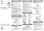
TOMOS
lll^ ri
^
^
'
TOMOS
A 35
workshop manual
www.1977mopeds.com
1.800.965.1977
colibri
TOMOS A 3 5
workshop manual
TOVARNA MOTORNIH VOZIL
TOMOS KOPER
SLOVENIA
www.1977mopeds.com
1.800.965.1977
COLIBRI A35
TOMOS
CONTENTS
Page
TECHNICAL DATA
3-5
STANDARD ELEMENTS
6
SPECIAL TOOLS
7-9
INTRODUCTION
10
FUNCTION OF COLIBRI ENGINE/A35
11 - 15
TROUBLESHOOTING
16-21
TRANSMISSION REPAIRS
22-27
MAGNETO REPAIRS
28-29
MAGNETO AND ELECTRICAL EQUIPMENT CHECKING
30
WIRING HARNESS
31 - 3 2
CARBURETOR REPAIRS
33-34
EXHAUST SYSTEM
35
CYLINDER, PISTON, REED VALVE REPAIRS
36-40
CRANKSHAFT AND MAINSHAFT REPAIRS
41 - 4 4
FRAME AND SUSPENSION
45-47
WHEELS AND BRAKES
48
OIL PUMP
49
A35 - SPECIAL FEATURES
50
www.1977mopeds.com
1.800.965.1977
TOMOS
COLIBRI
T E C H N I C A L DATA
Engine:
single cylinder, two cycle with reed valve, air cooled
Bore * Stroke:
38 x 43 mm
Piston displacement:
49 ccm
Compression ratio:
9,1 : 1
Brake horse power:
1,45 kW (5200 min-1)
Torque:
3,5 Nm (3500 min"1)
Gearbox:
automatic 2-steps. with two centrifugal cluthes
Gearbox oil quantity:
Valvomatic type A Suffix A - SAE 10 W 30 ccm 300
Ignition:
Flywheel magneto
Ignition advance:
1,5 + 0,2 mm B.T.D.C.
Contact breaker gap:
0,35-0,45 mm
Sparkplug:
BOSNA F 80, BOSCH W 4A2, CHAMPION L82,
NGK HS, EYQUEM 755, AC.C.42F
Spark plug gap:
0,5 mm
Fuel:
Mixture of gasoline 86-oct. and two stroke oil.
www.1977mopeds.com
1.800.965.1977
COLIBRI A35
TOMOS
TECHNICAL DATA
TRANSMISSION
i
speed
2"a speed
Z = 66
Mamshaft
Z = 26
Chain transmission 96 rollers
(66/17)
i = 3.8823
(53/24)
i = 2.461 5
(3.88*72/11)
1 = 25.4117
(2.46*72/11)
1=16 1189
(22/26)
i = 0.846
(25,4117*0.846)
i -
(16.11 0.846)
i = 13.631
Gearratio 1 s t speed
Gear ratio 2 ncl speed
Gearbox ratio 1 5 , speed
Gearbox ratio 2" r t speed
Chain transmission ratio
21.502
Total transmission ratio 1 s ' speed
n
Total transmission ratio 2 " speed
www.1977mopeds.com
1.800.965.1977
TOMOS
COLIBRI A35
TECHNICAL DATA
5
TORQUE
Position
Thread
Nm
Kpm
Pound
per foot
Spark plug
Mil 4x1,25
18
1,83
13,27
Cylinder cover
M7
12
1,22
8,85
Cylinder stud bolts
M7
15
1,53
11,06
Magneto flywheel
M10x1
30
3,06
22,12
Clutch of 1 s t speed
M10x1
25
2,55
18,44
2ndspeed driven gear
M14x1
80
9,15
59,0
Engine-frame fastening bolts
M8x1
25
2,55
18,44
RH engine cover
M6
7
0,71
5,16
LH engine cover
M6
6
0,61
4,42
Crankcase
M6
10
1,02
737
Mainshaft chain sprocket
M22
60
6,11
44,23
Swinging arm fastening screw
M1 2x1,25
35
3,57
25,81
Rear shock absorber
M10
25
2,25
18,44
Top fork lug
M12
35
3,57
25,81
Front and rear wheel spindle
M l 1*1
32
3,26
23,60
www.1977mopeds.com
1.800.965.1977
TOMOS
COLIBRI A35
STANDARD ELEMENTS
6
Ball bearings
TOMOS
Installation:
Code. No.
Bearing No.
Dimensions
d x D x b (mm)
Crankshaft
035.070 x 2
6203-C3
Crankshaft
035.202
608
8 x 22 x 7
Countershaft
035.072
035.031
6201
1 2 x 3 2 x 10
Mainshaft
035.037
6006
30 x 55 x 1 3
044.225x2
6201-Z
12x32x10
Wheel axle
1 7 x 40 x 1 2
Seal rings
TOMOS
Code. No.
Dimensions
d x D x b (mm)
Crankshaft
036.554
17x35x7
2
Mainshaft
036.620
35 x 47 x 7
1
Installation
www.1977mopeds.com
1.800.965.1977
pes.
COLIBRI/A35
TOMOS
SPECIAL TOOLS
732.746
MAGNETO FLYWHEEL PULLER
732.202
o
FLYWHEEL HOLDER
975.709
3=>
DIAL GAUGE
011.008
«=€
GAUGE PIN
732.193
DIAL GAUGE SUPPORT
I—
I>
735.888
CRANKCASE DIS-ASSEMBLY TOOL
- <
—'
www.1977mopeds.com
1.800.965.1977
COLIBRI A35
TOMOS
SPECIAL TOOLS
8
735.753
CRANKSHAFT MOUNTING FORK
•:•:•:•..'.'
731.155
CRANKSHAFT BEARING PULLER
702.856
DIS-ASSEMBLY CRANKSHAFT
BEARINGS
v.,
737.535
t
1
I
I1
CLUTCH SPRING SETTING TOOL
1
*ZZ7
737.536
d
ROLLER CLUTCH INSTALLER
www.1977mopeds.com
1.800.965.1977
TOMOS
COLIBRI/A35
SPECIAL TOOLS
732.367
v.
A
\|
MAINSHAFT NEEDLE BEARINGS
INSTALLER
f
E
BO=g
9
3
706.485
EXTRACTOR
706.472
EXTRACTOR BRIDGE
736.913
BRAKE SHOES SPRING INSTALLING
PLIERS
a=C
714.011
ENGINE REPAIR STAND
o=C
www.1977mopeds.com
1.800.965.1977
TOMOS
COLIBRI/A35
INTRODUCTION
10
This manual is intended as a help in "trouble shooting" and consequent repair procedure, which occours in
exploatation due to normal wear, but in most cases due to inproper maintenance of vehicle or engine.
For a dependable and prompt repair, follow the general rules as:
- Always use adequate tools.
- Where necessary, use a plastic mallet when dismantling individual assemblies,
- Clean individual parts prior to each check.
- Carefully clean all parts, oil movable parts, which are fitted by embossing them, and replace gaskets and
sealing rings prior to re-assembly.
- Observe torque figures table when screwing on screws and nuts.
The manual shows only the execution of dis-assembly operations in which necessary special tools are needed.
Dis-assembly of other parts (see explosion view in Spare parts catalogue) is meant like a common knowledge
of an qualified mechanic to whom this manual is dedicated.
Technical Service Department
TOMOS
www.1977mopeds.com
1.800.965.1977
TOMOS
COLIBRI/A35
FUNCTION OF COLIBRI ENGINE
11
TRANSMISSION PARTS
clutch drum
I s 1 speed clutch
crankshaft
roller clutch
•
2 nd speed clutch
I s t speed gear
countershaft
seltlocking rollerclutch
2 " speed gear
.
f r j
ID CfcOD
starting chain transmission
ucFcin
malnshaft
starter shaft/pedal shaft
drive chain sprocket
Legenda
rotating powered elements
free rotating elements
- stand still elements
www.1977mopeds.com
1.800.965.1977
TOMOS
COLIBRI/A35
FUNCTION OF COLIBRI ENGINE
12
I
ir
8
n—r=l""
^™p
Starting
www.1977mopeds.com
1.800.965.1977
TOMOS
COLIBRI/A35
FUNCTION OF COLIBRI ENGINE
13
1
i—T^
HCFDD
Idle run
www.1977mopeds.com
1.800.965.1977
TOMOS
COLIBRI/A35
FUNCTION OFCOLIBRI ENGINE
• CFDD
1 S| Speed
www.1977mopeds.com
1.800.965.1977
14
TOMOS 1
COLIBRI
SPARK PLUG CONDITIONS
A brown, tan or gray firing end is indicative of correct
engine running conditions and the selection of the
appropriate heat rating plug.
17
White deposits have accumulated from excessive
amount of oil in the combustion or through the use of
low quality oil. Remove deposits or a hot spot may
from.
Black sooty deposits indicate an over-rich fuel /air
mixture, or a malfunctioning ignition system. If no improvement is obtained, try one grade hotter plug.
Wet, oily carbon deposits form an electrical leakage
path along the insulator nose, resulting in a misfire.
The cause may be a badly worn engine or a malfunctioning ignition system.
A blistered white insulator or melted electrode indicates over advanced ignition timing or a malfunctioning
cooling system. If correction does not prove effective, try a colder grade plug.
A worm spark plug not only wastes fuel but also overloads the whole ignition system because the increased gap requires higher voltage to initiate the spark.
Adjust spark plug gap or replace.
www.1977mopeds.com
1.800.965.1977
TOMOS
ENGINE DOES NOT START
Fuel hoses
(piping)
Leakage, Flattened. Broken
Replace
Fuel filter in fuel
tank
Clogged
Clean
Fuel filter in carburetor
Fuel tank
Clogged
Source coil
Defective. Check resistance
Replace
Contact breaker
points
Not insulated. Not connected.
Incorrect gap. Pitted. Burnt.
Worn.
Adjust or replace
Condenser
Weak, Shorted, Bad contact
Replace
Ignition coil
Defective, check resistance
Replace
Plug cap
Faulty, No contact
Replace
Spark plug
Incorrect gap. Carbon deposit. Replace
Dirty. Oily. Burned.
Clean
Empty or low fuel level
Add fuel
"1'
I
1
Ponovm zagon
Re-start
NO
OK
SPARK
Is there fuel in carburetor?
Is spark blue and
strong?
YES
NO
Fuel tank
Fuel is deteriorated or dirty
Replace fuel
Re-start
www.1977mopeds.com
1.800.965.1977
OK
COLIBRI
18
1
\|
Piston, Cylinder
wall, Piston ring.
Worn, Broken, Scuffed,
Roasted.
Replace
Oil seal
Worn, cracked
Replace
Cylinder or
crankcase gasket
Air leakage
Replace
Reed valve
Leakage, broken
Replace
!I l
Re-start
NO
OK
I
B
COMPRESSION
Is compression
pressure correct?
www.1977mopeds.com
1.800.965.1977
ENGINE RURNS OVER BUT STALLS. ENGINE RUNS
IRREGULARLY, STOPS OR IDLES ROUGHLY.
TOMOS
FUEL
www.1977mopeds.com
1.800.965.1977
Carburetor
Needle valve is worn.
Pilot passages are clogget
Choke is closed
Water is mixed
Fuel hoses
(piping)
Leakage, Flattened, Broke
Fuel filter
Clogged
Fuel tank
Empty or fuel level is low
COLIBRI
19
Ignition timing
Contact breaker
points
Check timing
Not insulated. Not connected.
Incorrect gap. Pitted. Burnt.
Worn.
Adjust
Piston, Cylinder
wall. Piston ring.
Worn, Broken, Scuffed,
Roasted
Replace
Oil seal
Worn, cracked
Replace
Cylinder or
crankcase gasket
Air leakage
Replace
Adjust or replace
i_t
Re-start
Re-start
aI
NO
NO
1
SPARK
OK
Spark plug
Incorrect gap. Carbon deposit. Replace
Dirty Oily. Burned.
OK
COMPRESSION
Is compression
pressure correct?
www.1977mopeds.com
1.800.965.1977
Reed valve
Leakage, broken
Replace
TOMOS
COLIBRI
POWER LOSS
Carburetor
Fuel filter
20
Needle valve is worn.
Pilot passages are clogged.
Choke is closed.
Water is mixed.
Adjust
Clogged
Clean
Clean
Replace
Ignition timing
Fuel hoses (piping) Leakage, Flattened, Broken
Check timing
Adjust
Test ride
Test ride
Replace
NO
Fuel tank
Fuel is deteriorated or dirty
Replace fuel
\
Incorrect gap. Carbon deposit. Replace
Dirty. Oily. Burned.
ISKRA
SPARK
FUEL
Is compression
pressure correct-?
Spark plug
^
Piston,
Cylinder wall,
Piston rings
Worn, Broken, Scuffed,
Roasted.
Replace
Oil seal
Worn, cracked
Replace
Cylinder gasket
Air leakage
Replace
Lamelni ventil
Reed valve
Ne tesni.zlomljen
Leakage, broken
Zamenjati
Replace
J
COMPRESSION
' Check:
- brakes do not disengage = oil or grease control cabl&s
- exhaust pipe clogged = clean cylinder exhaust port and exhaust pipe
- intake filter clogged = clean
COMPRESSION
www.1977mopeds.com
1.800.965.1977
r1
h
Carburetor
Clogged
Clean, air blow
I
Fuel filter
Clogged
Clean
Re-start
O
/
H
o
NO
Fuel tank
zamazano
Fuel is deteriorated or dirty
Ol
OK
1
Replace fuel
m
FUEL
SPARK
. . .
O
z
m
Z
CO
-n
r
Ignition timing
Check timing
Adjust
Ignition coil
Detective, check resistance
Replace
Plug cap
Faulty, No contact
Replace
Spark plug
Incorrect gap. Carbon deposit.
Dirty. Oily. Burned.
Replace
m
O
PO
•
• •
SPARK
First check spark plug to find
cause.
www.1977mopeds.com
1.800.965.1977
o
ICD
J3
TOMOS
COLIBRI A35
TRANSMISSION REPAIRS
22
TROUBLES IN GEARBOX
When starting, engine runs in neutral gear and also with higher number of revs clutch does not engage:
- Throttle down and restart engine (oil is still cool and dense). When driving off, throttle up gradually to reduce
jerks.
- Loosen or broken retain spring of 1 sl speed gear selflocking clutch.
- 1 s ' speed gear selflocking clutch cage damaged.
When starting, the engine joggle:
- Not enough oil in the gearbox- fill up to the required level.
- Clutch drum or 1 s ' speed clutch shoe elements damage.
- 1 sl speed clutch retaining nut slackened (noise at engine idle run).
Clutch skidding (especially in cool weather):
- Uncorrect oil in gearbox - replace oil with standard.
Clutch not shifting from the 1 st into 2n6 or not engaging at all:
- Engine not powerful enough-see chapter 3 - Power loss
- Excessive oil in gearbox- check level.
- Brakes not disengaging - grease control cables.
- Clutch blocked - try to operate clutch at higher number of revs with motorized bicycle supported by stand.
- Countershaft and 1 s ' speed gear selflocking clutch seized - check the slide bearing surface.
When shifting to 2nd gear, clutch joggle.
- Chain sagged - tighten chain.
- Not enough oil in the gearbox - fill up to the required level.
With engine disengaged, the motorized bicycle is difficult to move forward - rearward:
- Check the 1 sl speed gear selflocking clutch for damage.
With engine in idle run in rearward motion blows:
- Check the starter shaft brake spring proper function.
Transmission not disengaged by idle run:
- Clutch drum incorporated roller clutch blocked.
When starting the engine does not turn over:
- Starter shaft holding clamp do not engage the inner chain transmission.
- Clutch drum incorporated roller clutch damaged.
In case of transmission part damage or failure is necessary to disassemble, only the RH engine cover and procede with disassembling and checking the parts as shown further.
Prior of operation drain the oil from the gearbox, dismantle the exhaust pipe (box wrench 10 mm, wrench 13
mm), the lateral protection shield fixed at swinging arm (wrench 10 mm), and slacken the cover screws. Attention at distance washers on starter shaft and countershaft.
www.1977mopeds.com
1.800.965.1977
COLIBRI A35
TOMOS
TRANSMISSION REPAIRS
23
Slacken the protective clutch washer with a socket 19 and with special tool 732.202 remove 1 sl speed clutch nut
(fig- D.
Detach clutch drum by hand or by means of an standard extractor in case of bushing seizure (fig. 2).
Fig. 2
Fig. 1
The starter shaft and the countershaft are connected by a starter chain, so both shafts will have to be taken out
together (fig. 3).
Remove the standard washers on the crankshaft and on the mainshaft (fig. 4).
f 11
f \
•*
Fig. 3
Fig. 4
www.1977mopeds.com
1.800.965.1977
COLIBRI A35
TOMOS
TRANSMISSION REPAIRS
24
Remove the sg-circlip and separate clutches 1 st and 2nd speed.
Dismantle both clutches, spring is removed with a screwdriver.
In this manner brake strips are realeased, and all three shoes can be removed.
Press pins out of shoes and check brake strips, spring inside of shoes and clutch hub for excessive wear (Fig. 5).
Clutch shoes must slip freely on clutch hub. In case of use of prescribed oil quantity and quality the wear of
clutch shoes linings is reduced at minimum.
'
tI \
Fig. 6
Fig. 5
At first, assemble the 1 M speed clutch at reversed order of dismantling. Particular care should be taken of brake
strips, they must protect each other against falling out.
Fix the main pin of the device 737.535 with the thinner part facing upwards. The spring joint must be placed in
the middle of one shoe. With the lever of the device insert the spring in the shoes groove. (Fig. 6).
To assemble the 2nd speed clutch turn the device over. The clutch hub with gear must be placed in the way the
gear is on bottom and the gap between two shoes fits with the pin. The manner of mounting the spring is the
same as mentioned before for the 1 s ' speed clutch.
Remove and inspect the 1st speed driven gear selflocking clutch in case of transmission troubles mentionated
on page 24. Remove the sg-circlip at the countershafts toothing. Unfasten the wire spring (Fig. 9) and separate
a small chain sprocket with roller cage. Remove the selflocking clutch and the rollers (Fig. 10).
In case of sliding surface damage of selflocking clutch replace the body (223.463). Check the sliding surface of
selflocking clutch on countershaft.
Dismantling of the needle clutch is necessary only in case of replacement.
A new needle clutch is pressed with special tool no. 737.536 (Fig. 7).
The needle clutch must be pressed with the signed side towards the center of the clutch drum, if not it may operate in the reverse direction.
Clearance between shoes and clutch drum rim is approx. 0,4 mm. Axial clearance of the clutch drum is from 0.1
m to 0.3 mm by means of inserting in the adjusting thrust washer of 0.3 mm or 0.5 mm under the clutch (fig. 5 A).
www.1977mopeds.com
1.800.965.1977
COLIBRI/A35
TOMOS
TRANSMISSION REPAIRS
737.536
marking
1
I
Fig. 7
www.1977mopeds.com
1.800.965.1977
25
COLIBRI A35
TOMOS
TRANSMISSION REPAIRS
26
If is necessary to replace chain sprocket or claw collar on pedal shaft of kick shaft, first remove protective ring
(fig. 8 1) and spring washer (fig. 8 2). During assembly take care that the thinner part of collar in mounted forward or else, the brake spring slides across the chain sprocket. Check the chain for overtension or some other
damage.
®
©
®
PTT
\
7
'O
Fig. 8
A damage of sliding surface of 1 st speed driven gear and countershaft may be caused due to low oil quantity in
the gearbox. Fix the countershaft into a vice and unscrew the nut with wrench 19 and remove the 2nd speed gear
with an extractor. Replace damaged parts.
Reassemble the countershaft in the reversed order of dismantling.
Use of grease is not suggested because it may impede the function of the selflocking clutch. Put the chain
sprocket with cage so that the beginning of wire spring is turned 90° left-ward from spring nose. (fig. 9). Lock the
wire spring to riveted nose on the selflocking clutch body.
Before tightening nut, it is necessary to check the proper function of the assy. Firmly hold 2nd speed driven gear
with the left hand and the clutch drum with the right hand. When clutch drum rotates counterclockwise, both clutches idle, when it rotates clockwise the motion is transmited to the crankshaft (fig. 11).
www.1977mopeds.com
1.800.965.1977
COLIBRI/A35
TOMOS
TRANSMISSION REPAIRS
27
yj^^fc
l
U*
K]
#c
Fig. 10
Fig. 9
Fig. 11
www.1977mopeds.com
1.800.965.1977
>
COLIBRI/A35
TOMOS
MAGNETO REPAIRS
28
In case of any magneto faulty part replacement actuate with dismantling at sequent parts as follows:
- starting lever pedal (wrench 11, plastic mallet)
- side protection shield fixed on swinging arm (wrench 10)
- engine cover (flat screwdriver)
- flywheel nut (socket wrench 17, flywheel holder=special tool 732.202=fig. 12)
- flywheel (wrench 32 and 19, flywheel extractor=special tool 732.746=fig. 13)
- stator plate (flat screwdriver)
1^ \
jfl
\
H^H
&cs3
;^^*™"jf
1
Fig. 13
Fig. 12
For proper function of the engine is essential a correct ignition timing. The ignition advance should be i 5 ' 0 - 2 m m *
The most common cause of incorrect timing is due wear or damage of contact breaker points, wear of cam actuated breaker nose lever, damage of condenser. To provide the exact timing is necessary to replace faulty
parts and proceed (fig. 14) as follows:
- Screw the special tool 732.193 and dial gauge 975.709 with gauge pin 011.008 into the spark plug hole. By
rotating the flywheel put the piston to the T.D.C. and set the dial gauge to zero.
- With the flywheel in T.D.C. set the contact breaker points gap between 0,35 to 0,45 mm
- With a test light, buzzer or Ohm meter determine when contact breakerpoints connection is made. The testing device must be connected to the short circuit (black) wire and to the ground of the engine. At the moment of connection of the points the test battery light will glow brightly, the buzzer will change the acoustic
frequence or the Ohm tester will show approx. zero Ohms.
- Rotate the flywheel in the clockwise direction until the dial gauge will show the value of 1,5 mm
- By means of oblong fixing openings rotate the stator base plate and find a contact breaker points connection opening position (test indication).
- Tighten the stator base plate and recheck the ignition advance which should be max. 1,7 mm
- In case of excessive advance, the stator base plate should be rotated in the direction of entine rotation (see
arrow of flywheel). In case of insufficient advance turn the plate in the opposite direction.
- In case of uncapable timing setting with a stator base plate rotation provide with the contact breaker points
gap setting but under prescribed limits.
- For efficient spark intensity or high ignition voltage is essential a proper abris adjustament. As a matter of fact,
it is the distance between the edge of the ignition coil pole shoe and the receeding magnet pole edge at the
opening point of the contact breaker and it should be within the range of 12 ± 2 mm (0.473 ± 0,079 in). The
gap should be measured the moment the intensity of light or sound frequency is changed on the gauge (fig.
14).
www.1977mopeds.com
1.800.965.1977
TOMOS
COLIBRI/A35
MAGNETO REPAIRS
29
r\
BTDC
12 m m 2 '
0,35-0,45
Fig. 14
Note:
For a good ignition must be provided a proper correlation between ignition advance, contact breaker points gap
and abris.
www.1977mopeds.com
1.800.965.1977
TOMOS
COLIBRI/A35
MAGNETO AND ELECTRICAL
EQUIPMENT CHECKING
30
The flywheel should be checked by visual inspection for mechanical damage and proper cone. Check deflection by help of the crankshaft.The maximum permissible axial deflection amounts to 0.1 mm and radial deflection to 0.3 mm.
The ignition coil both internal and external can only be checked if a special monotester is available. The chekking procedure is laid down by the mototester's manufacturer. If there is no mototester available, a possible fault
can be established by replacing a truly good sample coil for the existing coil.
The lighting coil should be checked with engine in operation (2000-3000 r.p.m.) To check the coil, use a Voltmeter and an appropriate bulb of the same rated power (W) as magneto. If there is no bulb of adequate power
available, interconnect an appropriate number of bulbs of an inferior power. If a bulb of an inferior power is used
it may blow at high revs.
Contact breaker: Check the contacts and the cam nose for wear. Insert an insulating mass between the two
breaker contacts and by an OHM-meter make sure the parts are electrically disconnected (there exist a possibility of uncture on the bearing bush or fixing bolt insulation).
Fig. 15
To check the capacitor it should be separated from other electrical components of the magneto.
Check the capacity by means of a capacitance meter and the ability of the capacitor to retain an electric charge.
Measurements and checking are carried out under the instruction of the meter's manufacturer.
Note
Caution is recommended in handling the noninsulated parts since there is a possibility of an electric shock. The
capacitor should, therefore, be discharged by connecting the two contacts.
COLIBRI:
Detach the fairing (cross screwdriwer) and the headlamp assy, (wrench 10) fig. 15 to achieve to the main electric wire harness and tachometer's leads.
Remove the carburetor protection shield and fuel tank to easily work on HT igniton coil and horn (fig, 16).
Replacement of voltage regulator is obtainable with exhaust pipe and RH protection shield dismantling (fig. 4).
A35: The ignition coil and voltage regulator are placed under side protection shields, as on A3.
Electric wiring and combination switches are checked according to the wiring diagram.
The voltage regulator should be checked when bulbs blow frequently. During the check the engine should be
operating and the lights switched on, alternatively. The voltage should always read 12 ± 0.5 V. Before replacing
the regulator, make sure the improper operations is not due to poor earth connection contact.
The direction indicator relay should be checked within in the wiring system. Previously check the bulbs and
direction indicators switch.
The STOP switch should be checked by a pilot bulb or OHM-meter.
www.1977mopeds.com
1.800.965.1977
RH FRONT
INDICATOR
12V 10W
—>-
INDICATOR WARNING
LAMP 12V 1,2W
LIGHT
SWITCH
-
IGNITION
COIL
ENGINE STOP
SWITCH
w
B
-=>-
NEUTRAL IDICATOR
LAMP 12V 1.2W
HIGH BEAM
LAMP 12V I.2W
FRONT BRAKE
LAMP SWITCH
1
on
RH REAR
INDICATOR
12V 10W
A . C . REGULATOR
12V 60W
AA
STOP LAMP
12V 10W
®y-
HEAD LAMP
12V 25/25W
tg)
EL.
TAIL LAMP
12V 4W
I M,
INDICATOR
RELAY
MV
LH FRONT
INDICATOR
12W 10W
\l
-£>-
REAR BREAK
LAMP SWITCH
H
O
o—o •
o
ENGINE
STOP
SWITCH
o
#
o
o
—.0
LIGHT
SWITCH
01
3
o—©
o
LIGHTING
DIMMER
SWITCH
o
c^^>
o
•
O
, I I
LIGHTING INDICATOR HORN
DIMMER SWITCH
SWITCH
SWITCH
o
o^>
O
O-MD
O
O
O
o
o
o
C^^>
O
O—O
O
o
r*
o
C^K)
HORN
SWITCH
INDICATOR SWITCH
www.1977mopeds.com
1.800.965.1977
i
^
GENERATOR
12V fiOW
LH REAR
INDICATOR
IcV 10W
ENGIN
FRONT BRAKE
LAMP SWITCH
RH FRONT
INDICATOR
12V IOW
INDICATOR WARNING^
LAMP IZV I . 2 W
ST0P
LIGHT
SWITCH
^ ^
A . C . REGULATOR
IZV 60W
SWITCH
m
¥?
HORN
RH REAR INDICATOR
IZV IOW
AA
NEUTRAL INDICATOR
LAMP 12V l , 2 W
AA
STOP LAMP
IZV IOW
HIGH BEAM
INDICATOR 12V l.Z'
=^C-
HEAD LAMP
IZV Z5/Z5W
TAIL LAMP
IZV 4W
vy
LH FRONT
INDICATOR
IZV IOW
UU
-
REAR BREAK
LAMP SWITCH
«
C^^3
o
o
ENGINE
STOP
SWITCH
o
•
#
0
o
c^^>
LIGHT
SWITCH
01 o - o o
3 O C^K)
LIGHTING
DIMMER
SWITCH
o
•
o
If
GENERATOR
IZV BOW
LIGHTING INDICATOR HORN
DIMMER SWITCH
SWITCH
SWITCH
O
CN—o
O
0 ^ 3
0
o
o
o
o
o
C^^D
O
c^«o
o
o
T*
INDICATOR
RELAY
o
C^^D
HORN
SWITCH
INDICATOR SWITCH
www.1977mopeds.com
1.800.965.1977
LH REAR INDICATOR
IZV IOW
IGNITION
COIL
TOMOS
COLIBRI
CARBURETOR REPAIRS
33
In case of carburetor troubles mentioned in trouble shooting chapters No: 3, 4 and 5 on pages 19-21 proceed
with dismatling at sequent parts as follows:
- carburetor area protection shield (detach the rubber protection sheet, slackes the screwsflat screwdriver)
- fuel tank (screw on bottom side near horn attachment on frame and on rubber elements-box wrench 10 mm)
- carburetor cpl. with air filter and rubber dust protection (screw of fixing claw - flat screwdriver) fig. 16.
The intake silencer remains between the angle supports and engine thus is necessary to remove the engine to
replace it.
Fig. 16
Dismantle the carburetor into component parts (fig. 17). Clean the parts in gasoline (petrol) and blow them by
compressed air.
Replace if necessary worn parts and carefully reassemble, especially the needle valve and float. Sligthly oil the
air filter.
www.1977mopeds.com
1.800.965.1977
COLIBRI A35
TOMOS
CARBURETOR REPAIRS
0
w
M l
i^
/
»
j
®
i
JkJ^ 1
S
r^N
f^K
'
®9k
w%
*i
F
l^
DELLORTO
www.1977mopeds.com
1.800.965.1977
34
COLIBRI
TOMOS
EXHAUST SYSTEM
35
The exhaust system is one-piece welded steel pipe with removable baffle (flat screwdriver) fig. 18. The oil residue in exhaust gases tends to condense in the exhaust system, becoming a hard carbon deposit over a certain
time period. The baffle could be cleaned with a steel brush. The exhaust pipe could be cleaned with a chemical
solution. Highly effective and relatively cheap solution is caustic soda dissolved in water in ratio 1 : 3.
1
Fig. 18
ATTENTION
Caustic soda is very dangerous chemical. Always wear protective clothing with eye protection!
Retain to the chemical producer's warnings and use routine!
Caustic soda-especially at above recommended strength reacts violenty with aluminium alloy and will
cause severe damage. Avoid the contact of caustic soda solution with engine aluminium alloy parts!
Carefully pour the solution into the one end plugged exhaust pipe. Do not plug the open end of quite fully filled
exhaust pipe! The solution should be left for its dissolving action to take place. Note that the soluton will give off
noxious fumes throughout its disolving process - the system must therefore be placed in well ventilated area.
After the required time has passed, carefully pour out the solution and flush the system through with clean, fresh
water.
www.1977mopeds.com
1.800.965.1977
COLIBRI/A35
TOMOS
CYLINDER, PISTON, REED VALVE REPAIRS
36
In case of mentionated parts troubles in trouble shooting chapters No. 2, 3 and 4 on pages 18 - 20 proceed with
dismantling at sequent parts as follows:
- carburetor
- exhaust pipe
- head cover and cylinder (box wrench 11 mm)
- piston (suitable pliers and gudgeon pressing pin)
Check piston and cylinder surfaces for possible damages. With micrometer check piston dia on points d1, d2,
d3 at right angles to gudgeon pin and compare the readings with the corresponding group on piston and in the
table (fig. 19).
-<3
-
d2
• e -
Skupina
Group
d1
d2
d3
ovalnost
round-off.
A
37,955
37,865
37,775
0,045
B
37,965
37,875
37,785
0,045
A
1.4954
1.4919
1.4883
0.0018
B
1.4958
1.4923
1.4887
00018
mm
in
PISTON
*l
D
Skupina
Group
Fig. 19
A
B
38,010' 0 0 1
38,020' ooi2 °
1 5 0 0
» 0.004
CYLINDER
1.504' 0008
in
CD
^±0,2
3*4±0,^
50+0,5
Bore taper and come-shaped:
D, = max. 0,012 mm (0,473 • 10'3 in)
www.1977mopeds.com
1.800.965.1977
TOMOS
COLIBRI/A35
CYLINDER, PISTON, REED VALVE REPAIRS
37
Upon the request of the market there are available two different pistons: 50 km/h (30 m.p.h.) - fig. 20 and 40 km/
h (25 m.p.h.) - fig. 21 with their own function diagram.
13
r~\
•nl
(*->
m
to
m
H
O C5LR
1
f
T.D.C.
IGNITION ADVANCE
INTAKE
TRANSFER
EXHAUST
*?/
«V|/
•o
p
o
— 1
Fig. 20
Z6.0
w <y
TTv'
• ^
:J
d R 3.0
:H
<
J
tf"5
*•
l J r—, 1 S
(
)
« J
h<r
p
1°
j
|
so
-i
C"J
8
_te_
www.1977mopeds.com
1.800.965.1977
1
IVI
TOMOS
COLIBRI/A35
CYLINDER, PISTON, REED VALVE REPAIRS
38
IGNITION ADVANCE
INTAKE
TRANSFER
EXHAUST
u
Fig. 21
www.1977mopeds.com
1.800.965.1977
TOMOS
COLIBRI A35
CYLINDER, PISTON, REED VALVE REPAIRS
39
Damage to reed valve may be caused also by steel material run-down (see function on fig 22, assy, parts
fig-23).
1
PISTON AT T.D.C.
PISTON AT B.D.C.
Fig. 22
www.1977mopeds.com
1.800.965.1977
TOMOS
COLIBRI/A35
CYLINDER, PISTON, REED VALVE REPAIRS
40
NOTE:
Replacement of cpl. reed valve is suggested.
Fig. 23
Check conrod bending by help of two calippers (Fig. 24). Check the needle bearing clearance and bearing rolling surface for damage.
n
Fig. 24
www.1977mopeds.com
1.800.965.1977
TOMOS
COLIBRI A35
CRANKSHAFT AND MAINSHAFT REPAIRS
41
In case of mentionated repairs is necessary to dismantle the engine from the fixing supports of swinging arm
assy. (fig. 25).
Upon previously described procedure dismantle magneto, transmission parts, carburetor and cylinder.
Fig. 26
Fig. 25.
Unscrew the crankcase halves connecting screws.
Install on the magneto side a case splitter tool 735.888 with the three magneto base plate fixing screw. With
wrench 13 mm screw on the device A and detach both halves (fig. 26).
Detach the crankshaft from the RH crankcase half with a plastic mallet (fig. 27). In case of remaining ball bearing on the crankshaft remove it with the extractor 731.155 (fig. 28).
lib.
Fig. 27
Fig. 28
www.1977mopeds.com
1.800.965.1977
TOMOS
COLIBRI/A35
CRANKSHAFT AND MAINSHAFT REPAIRS
42
Crankshaft Inspection
Check clearance of the conrod small and big end bearing assemblies.
Check the crankshaft between the center of a horisontal alignment tool and measure the out-of - round on all
the points indicated in fig. 29.
Permissible out-of-round should be within 0.02 mm (0.008 in) at check points 2 and 0.01 mm (0.004 in) at check
points 1 and 4. Check if the crankshaft conical part is damaged, inspect the thread on semiaxles and the keyway.
Fig. 29
Note
As required, centering is only carried out with a copper hammer, grip pliers and two levers.
www.1977mopeds.com
1.800.965.1977
COLIBRI/A35
TOMOS
CRANKSHAFT AND MAINSHAFT REPAIRS
43
Check both crankcase halves for possible damages or distorsions, particularly the joint surfaces, to avoid later
leaking of oil from gearbox.
Check all bearings, if clearance is noticed, the bearings must be replaced.
Remove seal rings by screwdriver. For disassembly of ball bearings and seal rings assembly alternatively use a
pressing pin 702.856 (fig. 30 and 31).
Fig. 30
Fig. 31
Crankshaft is impressed in crankcase halves by extractor 735.888 actuating with screw B (fig. 32 and 33) wrench 24 and 13. In case of machine press assembly is necessary a use of crankshaft insert forks 735.753 to
prevent crankshaft deflection.
,
Fig. 32
Fig. 33
www.1977mopeds.com
1.800.965.1977
COLIBRI A35
TOMOS
CRANKSHAFT AND MAINSHAFT REPAIRS
44
In case of mainshaft toothing damage replace it. Slacken the chain sprocket nut by a wrench 30 mm and using
the special tool 732.202 (fig. 34). Knock out the mainshaft by plastic mallet.
<& iL.**'*'
Fig. 34
In case of needle bearings or seal ring (incorporated in first needle bearing, code 035.502) damage knock out
them by suitable tool but pay attention not to damage bearing lying surface on mainshaft.
Pay attention on sequence assembly of needle bearings (fig. 35) by machine press tool and special tool
732.367.
035.503
035.502
0
seal ring
www.1977mopeds.com
1.800.965.1977
TOMOS
COLIBRI
FRAME AND SUSPENSION
45
The frame is rectangular steel tube construction type (fig. 36). Engine is peculiarly incorporated with supports in
rear swinging arm with hydraulic monoshock absorber (fig. 37 and 25). Front forks are common telescopicspring type (fig. 38).
Fig. 36
For a safe riding is necessary that here is none excessive clearance in front and rear forks assy, which is obtainable with tightening of steering bearings and replacement of sliding bushing at swinging arm.
In case of hydraulic monoshock absorber damage do not try to open the hydraulic part of assy, because is under high pressure thus replace the monoshock absorber cpl.
www.1977mopeds.com
1.800.965.1977
TOMOS
COLIBRI
FRAME AND SUSPENSION
46
Fig. 37
www.1977mopeds.com
1.800.965.1977
TOMOS
COLIBRIA35
FRAME AND SUSPENSION
The front fork lower leg can be removed as it is shown in fig. 38.
- by unscrewing remove lower leg from the front fork (fig. 38/1)
- the spring will remain attached either to the upper or to the lower screwed plug
- the upper plug should be removed after taping out the elastic pin (fig. 38/2)
- the lower plug can be removed with longer alien key (9 mm), (fig. 38 3)
47
remove by unscrewing
Checking:
Lenght of new spring: L = 215 mm
Wear limit: L = 200 mm
Check the outer and inner surfaces of the stanchions for sign of excessive wear.
Check for excessive play and for the straightness of the fork legs.
Reassemble in reverse order of dismantling.
The spring and sliding surfaces should be greased with water resistant grease (LIS 2)
www.1977mopeds.com
1.800.965.1977
COLIBRI A35
TOMOS
WHEELES AND BRAKES
48
Wheels are cast aluminium alloy type. No special maintenance is required as usual ball bearings greasing and
wear checking.
Brakes are drum type (fig. 39) thus there is a periodically need of linings dust (non asbestos) cleaning; cable
controls, brake operating cam and brake shoes support pin greasying. Disassembly of brake shoes is easier
with pliers - special tool 736.913.
/
Mi o >J1
^ ^ ^ ^
Fig. 39
BRAKE DRUM (front and rear wheel)
•0.5
Inside diameter (new one)
Max. wear diameter
90 -1.5
"" mm
90,10 mm
BRAKE SHOES (front and rear brake)
Breaking surface
Brake lining thickness (new one)
Max. wear thickness
28,8 cm2
4 mm
2.2 mm
www.1977mopeds.com
1.800.965.1977
TOMOS
COLIBRI
OIL PUMP
49
After assembly or repair of models with oil pump you must keep to the following instructions:
The pump is connected to the magneto nut on the crankshaft by a special clutch, (fig. 42 1)
- Unscrew the bleed screew on the oil pump and wait until oil from the tank under the seat flows to the pump.
The screw is then screwed on (fig. 40).
- Pour approx. 1 I gas mixture in the ratio od 1:50 (2% oil) into the fuel tank and start the engine. Let the engine
run of for approx. 5 min so as to make the oil pump push oil to the engine.
- Fill up the fuel tank with regular gas.
Take care lest oil level in the oil tank does not fall under the marking MIN. Pay special attention to the routing
of the oil lines to and from the oil pump. If the outflow line is crimped, oil will not reach the carburetor causing
severe engine damage.
Fig. 40
www.1977mopeds.com
1.800.965.1977
TOMOS
A35
A35 - SPECIAL FEATURES
50
Special features
The A-35 motorcycle is a combination of the A-3 models (frame and swinging leg), Fig. 42 and the A-5 (Colibri) (driving unit). The front suspension is identical for all 3 models. (A-3, A-5 and A-35).
There is no functional difference in the electrical system of both models, with the only exception that the cable
harness with the A-5 is of a single piece while it consists of two parts with the A-35 (front and rear).
www.1977mopeds.com
1.800.965.1977
PROMO, D.O.O. KOPER, PROIZVODNJA DVOKOLES - TWOWHEELERS PRODUCTION, SLOVENUA
6000 KOPER, SMARSKA C. 4, TEL: 066/31-111, FAX: 066/33-207, TELEX: 34-118
www.1977mopeds.com
PRINTED
BY
1.800.965.1977