1
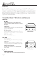
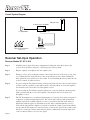
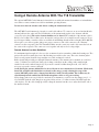
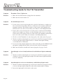
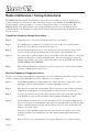
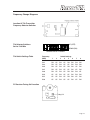
e
es re
th su
T:
N ead d en.
r n n
TA
R es to me aratio
i
PO nut e t pe
IM w mi l sav em o
l
fe i st
a s w sy
ng on er
ki cti op
Ta tru pr
s
in
FM Wireless Listening System
Installation and User Manual
Transmitter Model T18
Receiver Models R7, R7-4, R7-6, R700
MAN 057
PERSONAL PA BROADCASTING SYSTEM
Installation and User Manual
Contents:
Page
Overview
4
Transmitter Controls and Features
4
Transmitter Set-Up and Operation
Antenna Connection
Power Connection
Audio Connection
Using a Microphone
5
Receiver Set-Up and Operation
6
Receiver Battery Information
7
Receiver Management Suggestions
8
Using a Remote Antenna
9
Troubleshooting
10
Radio Interference / Tuning Instructions
12
FCC Part 90 Licensing Information
14
Warranty
17
Page 3
Overview
The T18 is an FM Listening System Transmitter which operates in the 72 MHz - 76 MHz frequency band.
This versatile transmitter is easily integrated with your existing sound system or can be used with a
microphone as a stand-alone system. Designed for simultaneous language interpretation and other business
applications, the T18 broadcasts to a variety of Williams Sound personal receivers including the R7, R7-4,
R7-6, and R700. Federal regulations call for operators of transmitters such as the T18 to be licensed under
Part 90 of the FCC Rules and Regulations. Form 600, the appropriate Schedules, and directions for license
application are contained in this manual.
Transmitter Model T18 Controls and Features:
Front Panel:
Mic Input:
3.5mm mini phone jack for use with Williams Sound
condenser microphones. Supplies +DC power for condenser
microphones.
Level Control:
Screwdriver-adjust control used to set the microphone input
level or the audio input level.
ON Indicator Light:
Glows when power is applied to the transmitter. There is no
on/off switch. The T18 is designed to be left on continuously.
Williams Sound
Auditory Assistance Transmitter
Mic
Level
-
Audio On
+
T18 Front Panel
Audio Indicator Light:
Flashes when audio signal is present.
Rear Panel:
Power Input Jack:
Connects to the plug on the wall transformer power supply.
Audio Input:
An RCA-type jack for connecting the transmitter to other
sound systems. Accepts line-level, unbalanced audio inputs.
Antenna Output Connector:
A 75 Ohm, F-type connector for use with the ANT 005
remote antenna.
FM Transmitter Model PPA T18
Williams Sound Corp., Minneapolis, MN, USA
Antenna
Power
12 VAC
100 mA
75 Ohm
Audio In
Hi-Z
Line
Made in U.S.A
T18 Rear Panel
Top Panel:
Antenna Mounting Stud:
For use with the "rubber duck" type antenna supplied with the T18.
Page 4
Transmitter Set-Up and Operation
Step 1: Install the antenna.
The "rubber duck" whip antenna fits into the hole on top of the transmitter and threads onto a mounting stud
inside. Guide the antenna onto the stud and turn it clockwise to tighten. Do not use excessive force to tighten
the antenna. It only needs to be finger-tight.
See page 9 for instructions on using the remote antenna.
Step 2: Connect the transmitter to power.
The T18 is supplied with a wall transformer power supply. Plug the transformer into a 120 Volt, 60 Hz wall
outlet. Then plug the power cord into the "Power" connector on the rear panel of the T18. The green indicator
light on the front panel of the T18 should glow when the power is connected.
There is no on/off switch. The T18 is designed to be continuously on. The wall transformer can be plugged
into a switched outlet that turns on when the other sound equipment is turned on.
If turning the T18 on creates a hum or buzz in the sound system, see the Troubleshooting section on page 10.
Step 3: Make audio connections.
If you will be using the T18 with an existing sound system
Refer to the Overall System Diagram on the next page. Use the audio cable supplied to connect the T18
"Audio In" jack to an appropriate audio output jack on the sound system mixer or amplifier. The T18 is
designed to work with an unbalanced, line-level audio signal. Suitable connections are:
First Choice:
TAPE OUT or LINE OUT Jack
Second Choice:
BOOSTER or BRIDGING Jack
Third Choice:
Speaker Terminal, 8 Ohm Tap
If your amplifier or mixer does not have RCA-type connectors, you can obtain adapters from your Williams
Sound Authorized Dealer or a local radio parts store. If the TAPE OUT jack is already in use, a Y-Cord can
be used to connect the T18 and a second device to the same jack.
If you will be using the T18 with its own microphone as a stand-alone system
Any Williams Sound microphone with a 3.5mm mini phone plug can be used with the T18. Plug the
microphone into the "Mic" jack on the front panel of the T18. The T18 supplies positive DC voltage on the
plug tip to power condenser microphones.
If you use both the Microphone input and the Audio Input on the T18, the signals will be mixed together.
Step 4: Use a receiver to test the system and set the input level control.
The steps on the following page explain receiver operation.
Page 5
Overall System Diagram
Microphones
Sound System Amplifier
Loudspeakers
Line-Level Output
Line-Level Input
FM Pocket Receivers
T18 Transmitter
w/Earphones
Receiver Set-Up & Operation
Receiver Models R7, R7-4, R16
Step 1
Install the battery: Open the battery compartment by lifting the tab at the bottom of the
receiver. Press the battery into place, observing proper battery polarity.
Step 2
Plug the earphone or headphone into the earphone jack.
Step 3
Turn the receiver on by rotating the volume control in the direction of the arrow on top of the
case. Turning the knob in the direction of the arrow will increase the volume. Turning the
knob against the arrow will decrease the volume. To avoid draining the battery, make sure the
receiver is turned off when not in use.
Step 4
If you are using the T18 with an existing sound system, make sure the sound system is turned
on. Have someone speak into a microphone while you listen with the receiver and earphone.
You should be able to hear their voice through the receiver.
If you are using the T18 with its own microphone, have someone speak into the microphone
while you listen with the receiver and earphone. You should be able to hear their voice
through the receiver.
Step 5
The T18 Transmitter has a screwdriver-adjust input level control located on the front panel to
compensate for different input signal levels. The yellow audio indicator light should flash
with the signal. If the sound through the receiver is clear and loud and the audio indicator
light flashes with the signal, no adjustment is needed. If the sound through the receiver is
weak and the audio indicator light does not flash even with the volume control turned all the
way up, turn the T18 input level control clockwise to increase the signal. If the sound is loud,
distorted, or broken up, and the audio indicator light is continuously on, turn the input level
control counterclockwise to decrease the signal.
Page 6
Additional Instructions for Receiver Models R7-4 and R7-6
The R7-4 and R7-6 Receivers feature four-channel and six-channel selector knobs, respectively. You’ll find
these controls on top of the receiver. Turn the selector knob until you hear the desired program.
Instructions for Monitor Receiver Model R700
Step 1
Plug the R700 power cord into a 120 VAC, 60 Hz electrical outlet.
Step 2
Attach the antenna to the connector on the rear panel of the R700.
Step 3
Turn the power switch on and adjust the volume control until you hear the signal from the
transmitter.
An optional remote antenna (ANT 005) may be used with the R700 to extend the reception range.
An external loudspeaker may be used with the R700. Connect the + (plus) loudspeaker wire to the tip
connection of a 1/4" mono phone plug. Connect the - (minus) loudspeaker wire to the sleeve connection of
the 1/4" mono phone plug. Insert the plug into the external speaker jack on the rear panel of the R700. This
will cut out the built-in speaker and deliver up to 1 Watt of audio power into an 8 Ohm speaker. The R700
speaker output jack may also be connected to the high level input of a PA amplifier. See the instructions
included with the R700 for more details.
Receiver Battery Information
In normal use, a heavy-duty 9 Volt battery such as the Eveready 216 will last about 10 hours. Alkaline
batteries such as the Eveready 522 will provide about 17 hours of use. If the sound becomes weak or
distorted, replace the battery. The indicator light may still be on, even with a battery that is weak. Do not
leave dead batteries in the receivers.
Rechargeable Batteries
The receivers can also use a rechargeable battery. We recommend only the 7-cell, 8.4 Volt types (BAT 003).
(Most batteries available through department and radio stores are 6-cell, 7.2 Volt types. They will not perform
satisfactorily with Williams Sound receivers.) A fully-charged battery (Williams BAT 003) will provide about
5 hours of use per charge. The battery may be recharged without removing it from the receiver.
The BAT 005 Single Charger has a cord that plugs into the receiver "EAR" jack to charge the battery. The
CHG 1269A Multiple Charger can charge 12 receivers simultaneously through the receiver "EAR" jacks.
Receivers can be left charging continuously when not in use. The receiver should always be turned OFF
while charging. It takes about 14 hours to fully charge the battery.
Battery Warnings
DO NOT ATTEMPT TO RECHARGE DISPOSABLE BATTERIES!
AVOID SHORTING THE PLUS AND MINUS BATTERY TERMINALS TOGETHER WITH METAL
OBJECTS. BATTERY DAMAGE AND BURNS CAN RESULT!
USE ONLY WILLIAMS SOUND SUPPLIED CHARGERS AND BATTERIES!
Page 7
Suggestions For Receiver Management &
Earphone Sanitation
Different types of facilities will use different approaches for receiver management and earphone sanitation.
Below are some options that customers have used successfully.
1
Regular users purchase their own receiver and take care of their own batteries and earphone.
2
Some facilities label the receiver and earphone with the names of regular users so each person uses
the same receiver and earphone.
3
Ushers issue receivers to people who request them. Earphones are sanitized after use. Foam ear
cushions can be replaced or washed with a mild detergent, rinsed thoroughly and air-dried. The EAR
022 Surround Earphone can be sanitized with an alcohol pad.
4
The receivers are stored in a multiple compartment storage case with a credit card or driver's license
left as collateral for the receiver.
5
Regular users purchase their own earphone or headphone and bring them to use with receivers at the
facility.
Page 8
Using A Remote Antenna With The T18 Transmitter
The optional ANT 005 Coaxial Antenna is intended for use with rack-mounted transmitters or in installation
areas where a remote antenna is needed for maximum operating distance.
Do not cut or alter the antenna cable before reading the instructions below!
The ANT 005 Coaxial Antenna is a length of coaxial cable with an "F" connector on one end and an 80-inch
antenna built onto the other end. The last 80 inches of the antenna make up the active element, which is
covered by nylon braid. The active element should never be altered. The remainder of the antenna cable is
RG-59 coax feedline. The feedline can be shortened if you have the tools to install a new F-connector. If you
need a longer feedline, extension cables are available from Williams Sound in 50 foot lengths (WCA 008 50).
Never splice coax cables together. Always use proper connectors. The cable connects to the "Antenna"
connector on the rear panel of the T18 Transmitter. Make sure the center wire on the cable enters the hole in
the center of the receptacle. The connectors screw together and only need to be finger-tight.
Remote Antenna Location Guidelines
For maximum signal strength, it is best to select an antenna location somewhere within the listening area. The
preferred location is towards the front of the listening area and above the seats. The active element (nylon
braid covered portion) should be kept straight, not coiled, and must be vertical.
Radio signals will generally pass through non-metal structures. The antenna can be mounted on a wall, in a
corner, or behind a wooden beam. It may also be hung vertically from the ceiling, with a small weight
attached to the end to make it hang freely. If you need to run the feedline through a wall, a 1/2" hole is
necessary to pass the connector through.
Avoid placing the antenna within four feet of steel beams or near structural steel elements. Metal studs,
ductwork, and foil-backed insulation can absorb radio energy, greatly reducing the range of the
system. DO NOT put the active element (last 80 inches) inside a metal conduit. The feedline may be
routed through metal conduit, but NOT with microphone cables or AC power wiring.
Nylon clamps and screws are provided to attach the Coax Antenna to a wall. Locate the clamps every 3 - 4
feet. DO NOT bend the cable sharply at any point. Allow at least a 3" radius for turns. DO NOT staple the
cable in place. Use the cable clamps provided or hang the antenna from the excess nylon braid at the end of
the antenna element.
Page 9
Troubleshooting Guide for the T18 Transmitter
Symptom:
Transmitter "Power" light not on.
Remedies:
1. Make sure the wall transformer is plugged into the transmitter.
2. Make sure the electrical outlet is on.
Symptom:
No sound through receivers.
Remedies:
1. If some of the receivers work, but others don't, check for bad batteries or earphones on
the receivers that aren't working. Check to see that the receiver frequency matches the
transmitter frequency. The frequency sticker is on the bottom of the transmitter and
inside the back cover of the receiver. If they do not match, see the Tuning Instructions.
2. If none of the receivers work, check to see if the power is connected to the transmitter
and the "Power" light is on. Check to see if the transmitter and receivers are set on the
same frequency. The frequency sticker is on the bottom of the transmitter and inside the
back cover of the receiver. If they do not match, see the Tuning Instructions.
3. Check to see if the Transmitter is connected properly to the sound system. See page 4.
4. Turn the screwdriver-adjust input level control located on the T18 front panel clockwise
to increase the input signal strength. Check to see that the audio light is flashing
occasionally but not continuously.
5. If you are not using an input signal from a sound system, make sure the Williams Sound
microphone is plugged into the "Mic" jack on the front of the T18 transmitter.
6. Make sure the antenna is installed and connected properly. See pages 5 and 9.
Symptom:
Sound through receivers is loud, but distorted. Audio Indicator Light is continuously
on.
Remedies:
1. Turn the screwdriver-adjust input level control located on the T18 front panel counterclockwise to decrease the input signal strength. The audio indicator light should flash,
not be lit continuously.
Symptom:
Sound through the receivers is weak and noisy. Audio Indicator Light is not lit.
Remedies:
1. Turn the screwdriver-adjust input level control located on the T18 front panel clockwise
to increase the input signal strength. The audio indicator light should be flashing
2. Increase the input signal level from the sound system.
Page 10
Symptom:
Scratchy noise when receiver volume control is adjusted.
Remedy:
1. Open the back of the receiver case by opening the battery compartment. Keep lifting on
the battery door and the back of the receiver case will open like a book.
2. Remove the screw from the center of the volume control and remove the knob.
3. Lift the clear plastic cover on the control and spray GC SPRA-KLEEN, LPS Contact
Cleaner, or equivalent into the control. Replace the knob and rotate the control several
times.
4. Replace the screw and close the case.
Symptom:
Buzzing or humming noise in sound system.
Remedies:
1. There is nothing wrong with the T18 Transmitter. One or more pieces of equipment in
the sound system are being disturbed by RF (Radio Frequency) signals produced by the
T18. The most likely suspects are your amplifier, mixer, or tape deck. The RF gets into
the other equipment primarily through the power cord, speaker wires, or unshielded
inputs, all of which can act as antennas.
Try moving the Transmitter away from the other sound equipment.
2. If remedy 1 does not solve the problem, we recommend using the optional Coax
Antenna (ANT 005), which should be located 15-20 feet away from the other sound
equipment. You may add additional RG-59 feedline, as needed.
4. If changing the Coax Antenna doesn’t help, it’s time to dig deeper into the problem. This
involves a slight modification to the equipment that’s causing the problem. Unless you
have the necessary technical skills, this is best left to a qualified electronics repair
technician. Call your Authorized Dealer or Williams Sound Corp. for more information.
Ask for the Bogen Buzz Paper.
Page 11
Radio Interference / Tuning Instructions
The PERSONAL PA is usually not disturbed by other radio services. However, there are few clear or
exclusive channels for radio services. One of the unique features of the Williams Sound PERSONAL PA
System is that the operating frequency can easily be changed in the field to avoid interference. The
PERSONAL PA can be quickly tuned to any of eight available frequencies by your Williams Sound
Authorized Dealer. The Transmitter is changed first. Then the signal produced by the Transmitter is used to
tune the receivers.
Transmitter Frequency Change Instructions
Step 1
Unplug the power cord from the Transmitter and remove the antenna.
Step 2
Use a phillips-type screwdriver to loosen the two screws on the rear of the Transmitter.
Remove the cover. Slide the circuit board out of the case.
Step 3
Use the diagram on the next page to locate the frequency selector switches on the circuit
board. Locate the switch programming chart on the bottom of the Transmitter case.
Step 4
Use a paper clip or small screwdriver (not a pencil point) to move the switches to correspond
with the switch positions on the programming chart. Select a new frequency at least two
channels away from the one you are experiencing interference on. DO NOT TOUCH ANY
OF THE OTHER ADJUSTMENTS!
Step 5
Re-assemble the Transmitter and plug it in. Connect a tape player or radio to the transmitter
to provide a tuning signal for the receivers.
Receiver Frequency Change Instructions
The R7 receiver tuning is determined by a single tuning coil, and is stabilized by automatic frequency control
circuitry. A tuning wrench (PLT 005) is needed to adjust the receiver tuning coil.
Step 1
Use the PPA transmitter as a tuning signal source. Make sure there is some kind of audio
input (tape or radio) to the transmitter so you have something to listen to.
Step 2
Disconnect the antenna from the transmitter. The receiver must be tuned under weak signal
conditions at enough distance from the transmitter to allow some noise to be heard.
Step 3
To expose the circuit board, open the battery flap first. The receiver back snaps open like a
book. Hold the receiver near the transmitter while beginning the tuning procedure.
Step 4
Use the diagram on the next page to locate the tuning coil. Use the earphone supplied with
the receiver to listen for the transmitter signal while you adjust the tuning coil with the tuning
wrench. Adjust the tuning coil slowly and carefully. Do not press down on the tuning slug.
Adjust for best audio quality.
Step away from the transmitter until some noise is heard. As you continue to move away
from the transmitter, keep adjusting for best audio quality until no improvement can be
discerned.
Step 5
Page 12
Re-tune all the receivers and mark the new frequency inside the case for future reference.
Frequency Change Diagrams
Location Of T18 Transmitter
Frequency Selector Switches
T18 Selector Switches:
Set for 72.9 MHz
UP (OFF)
1 2 3 4 5 6 7 8
DOWN (ON)
Switches set for 72.9 MHz
T18 Switch Settings Table
Frequency
(MHz)
Switch Settings
3
4
5
6
1
2
7
8
72.1
DN
UP
DN
UP
DN
DN
DN
DN
72.3
DN
UP
DN
UP
UP
DN
DN
DN
72.5
DN
UP
DN
UP
DN
DN
UP
DN
72.7
DN
UP
DN
UP
UP
DN
UP
DN
72.9
DN
UP
DN
UP
DN
DN
DN
UP
75.5
UP
UP
DN
UP
UP
DN
DN
DN
75.7
UP
UP
DN
UP
DN
DN
UP
DN
75.9
UP
UP
DN
UP
UP
DN
UP
DN
R7 Receiver Tuning Coil Location
Page 13
FCC License Instructions:
The T18 Transmitter requires an FCC Part 90 license for legal operation. We have enclosed a license form for
your convenience. Complete the form, following the instructions below, and mail it to the FCC at the address
listed in step 5. An $80.00 filing fee, payable to the FCC is also required. When the application is approved
and payment is received, the FCC will mail the license to you.
Important Note Be sure to fill in all required items completely, even if you are duplicating information.
Do not use phrases like "see above." The FCC will reject incomplete applications.
STEP 1
Make a photocopy of the license application Form 600. You'll need to copy the Main Form pages 1-2, as well
as Schedules D, E, & G.
STEP 2
Using a pencil, fill in the photocopied Main Form and Schedules D, E, and G as follows:
FCC 600 Main Form
1:
Enter the legal name of the person, business, or organization seeking a license.
Enter the appropriate voice phone number.
2:
3:
Enter the trade name under which the entity operates if different from the legal name.
4:
Enter its FAX number.
5:
Enter the mailing street address or PO of the entity. Enter the name of the
representative submitting the application next to Attention:
6:
Enter the city name of the mailing address.
7:
Enter the two-letter state abbreviation of the mailing address.
8:
Enter the appropriate zip code of the mailing address.
9-16:
Skip.
17:
Enter "N".
18:
Enter "D".
19:
Enter "I".
Skip.
20:
Skip.
21:
22:
Enter "P".
23:
Enter "I".
Enter "N".
24:
25:
Enter "N".
26:
Enter "IB".
Skip.
27:
28:
Enter "N".
29-33:
These questions require your own answers. Most applicants who are US citizens will
enter "N" in boxes 29-33.
34-38:
These questions require your own answers. Most applicants will enter "N" in boxes
34-37 and "Y" in box 38.
Page 14
39:
40:
41:
42:
43:
Enter the letter code which best describes the applicant. "I" = Individual,
"U" = Unincorporated Association, "P" = Partnership, "C" = Corporation,
"G" = Governmental Entity.
Type the name of the person signing the application.
Enter the title of the person signing the application.
Sign the form in this box.
Enter the signing date.
Schedule "D": Administrative Data of FCC Form 600
Licensee Name:
Enter the name of the person, business, or organization seeking the license as listed
in Box 1, Form 600.
Radio Service:
Enter "IB".
Call Sign or
Enter the name of the city and state in which you are located.
Station Location:
D1:
Enter "N".
D2:
Skip.
D3:
Skip.
D4:
Skip.
Enter the street address, city, and state abbreviation of the individual, business, or
D5:
organization seeking the license.
D6:
Enter your voice phone number.
D7:
Skip.
Skip.
D8:
D9:
Skip.
D10:
Skip.
Skip.
D11:
D12:
Enter the most appropriate choice of either "Simultaneous Language Interpretation"
or "Tour Guide Operation". Then enter "Range: Up to 400 ft. from portable
transmitter."
D13:
Enter "90.217".
D14:
Skip.
Schedule "E": Station Location Data of FCC Form 600
Enter the name of the person, business, or organization seeking the license as listed
Licensee Name:
in Box 1, Form 600.
Enter "IB".
Radio Service:
Call Sign or
Enter the name of the city and state in which you are located.
Station Location:
Skip.
E1-E8:
E9:
Enter "0.2".
E10:
Enter "O".
Page 15
E11:
E12:
Enter the Latitude and Longitude of the county in which your office is located in
degrees, minutes, and seconds. A local library can supply this information. Enter the
county and state in which your office is located.
Skip.
Schedule "G": Technical Data of FCC Form 600
Licensee Name:
Enter the name of the person, business, or organization seeking the license as listed
in Box 1, Form 600.
Radio Service:
Enter “IB”.
Call Sign or
Enter the name of the city and state in which you are located.
Station Location:
LOC:
Skip the first line. On the second line, underneath the box containing “A”,
enter “G”.
G1:
Enter “72–76”.
G2:
Enter “MO”.
Enter “1”.
G3:
G4:
Enter “68K0F3”.
G5:
Enter “0.026W”.
G6:
Enter “0.026W”.
G7:
Skip.
G8:
Skip.
STEP 3
Using the completed photocopy as a guide, TYPE OR PRINT the information onto the Main Form pages 1-2,
and Schedules D, E, and G.
STEP 4
Staple the forms together in the upper left corner. The main form should be on top and schedules behind in
alphabetical order.
STEP 5
Mail the signed, completed form, and a check for $80.00 made out to the Federal Communications
Commission, to:
Federal Communications Commission
P.O. Box 358220
Pittsburgh, PA 15251-5220
STEP 6
Celebrate! You're finally done!
Page 16
Warranty
Williams Sound Transmitters and Receivers are warranted against defects in workmanship and materials for
THREE YEARS. Microphones, earphones, cables, carry cases, rechargeable batteries and chargers are
warranted against defects in workmanship and materials for 90 DAYS. This warranty does not extend to
intentional or accidental physical damage. This warranty applies only to products returned to Williams Sound
for service. To return a product for service, call the phone number on the next page and request a Return
Authorization (RA) number.
Page 17
Copyright 1995, Williams Sound Corp.
MAN 057