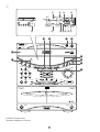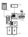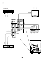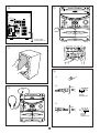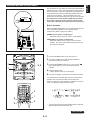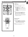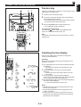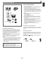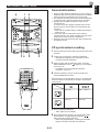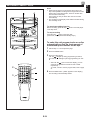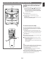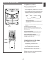
1
Active Servo
Technology
DISC CHANGE
MINI COMPONENT SYSTEM
GX–70
GX–7
OPEN/CLOSE
1
PTY
SEE
K
Y
LA
DISP
T
STAR
2
DISC
IT
ED
DE
3
MO
FRE
PROGRAM
PRESET/TUNINGBAND
MUSIC
Q PS/P
TY/R
RAND
T/CT
REPE
AT
OM
VOLUME
A/B/C/D/E
CD
DOWN
INPUT
MEMORY
UP
TAPE 1/2
REC/PAUSE
MODE
NORMAL
HIGH
DOLBY NR
POWER
UP
INPUT
DOWN
USER
DUBBING
PHONES
TIMER REC
MEMORY
AUTO/MAN’L
Active Servo
Technology
TIMER
TIME ADJ
HOUR
PLAYBACK
MIN
1
2
REC/PLAYBACK
DOLBY B NR
EJECT
EJECT
Active Servo
Active Servo
Technology
Technology
Natural Sound Mini Component System
Chaîne Mini de la série “Natural Sound”
OWNER‘S MANUAL
MODE D‘EMPLOI
SAFETY INSTRUCTIONS
7
Wall or Ceiling Mounting – The unit should be mounted to
a wall or ceiling only as recommended by the
manufacturer.
8
Ventilation – The unit should be situated so that its
location or position does not interfere with its proper
ventilation. For example, the unit should not be situated
on a bed, sofa, rug, or similar surface, that may block the
ventilation openings; or placed in a built-in installation,
such as a bookcase or cabinet that may impede the flow
of air through the ventilation openings.
9
Heat – The unit should be situated away from heat
sources such as radiators, stoves, or other appliances
that produce heat.
CAUTION
RISK OF ELECTRIC SHOCK
DO NOT OPEN
CAUTION: TO REDUCE THE RISK OF
ELECTRIC SHOCK, DO NOT REMOVE
COVER (OR BACK). NO USER-SERVICEABLE
PARTS INSIDE. REFER SERVICING TO
QUALIFIED SERVICE PERSONNEL.
• Explanation of Graphical Symbols
The lightning flash with arrowhead
symbol, within an equilateral triangle,
is intended to alert you to the
presence of uninsulated “dangerous
voltage” within the product’s
enclosure that may be of sufficient
magnitude to constitute a risk of
electric shock to persons.
10 Power Sources – The unit should be connected to a
power supply only of the type described in the operating
instructions or as marked on the unit.
11 Power-Cord Protection – Power-supply cords should be
The exclamation point within an
equilateral triangle is intended to alert
you to the presence of important
operating and maintenance
(servicing) instructions in the
literature accompanying the
appliance.
routed so that they are not likely to be walked on or
pinched by items placed upon or against them, paying
particular attention to cords at plugs, convenience
receptacles, and the point where they exit from the unit.
12 Cleaning – The unit should be cleaned only as
recommended by the manufacturer.
WARNING
TO REDUCE THE RISK OF FIRE OR
ELECTRIC SHOCK, DO NOT EXPOSE THIS
UNIT TO RAIN OR MOISTURE.
1
Read Instructions – All the safety and operating
instructions should be read before the unit is operated.
2
Retain Instructions – The safety and operating instructions
should be retained for future reference.
3
Heed Warnings – All warnings on the unit and in the
operating instructions should be adhered to.
4
Follow Instructions – All operating and other instructions
should be followed.
5
Water and Moisture – The unit should not be used near
water – for example, near a bathtub, washbowl, kitchen
sink, laundry tub, in a wet basement, or near a swimming
pool, etc.
6
13 Nonuse Periods – The power cord of the unit should be
unplugged from the outlet when left unused for a long
period of time.
14 Object and Liquid Entry – Care should be taken so that
objects do not fall into and liquids are not spilled into the
inside of the unit.
15 Damage Requiring Service – The unit should be serviced
by qualified service personnel when:
A. The power-supply cord or the plug has been
damaged; or
B. Objects have fallen, or liquid has been spilled into the
unit; or
C. The unit has been exposed to rain; or
D. The unit does not appear to operate normally or
exhibits a marked change in performance; or
E. The unit has been dropped, or the cabinet damaged.
16 Servicing – The user should not attempt to service the unit
beyond those means described in the operating
instructions. All other servicing should be referred to
qualified service personnel.
Carts and Stands – The unit should be used only with a
cart or stand that is recommended by the manufacturer.
17 Power Lines – An outdoor antenna should be located
6A A unit and cart combination should be
away from power lines.
moved with care. Quick stops,
excessive force, and uneven surfaces
may cause the unit and
cart combination to overturn.
18 Grounding or Polarization – Precautions should be taken
so that the grounding or polarization is not defeated.
2
19 For US customers only:
EXAMPLE OF ANTENNA GROUNDING
Outdoor Antenna Grounding – If an outside antenna is
connected to this unit, be sure the antenna system is
grounded so as to provide some protection against
voltage surges and built-up static charges. Article 810 of
the National Electrical Code, ANSI/NFPA 70, provides
information with regard to proper grounding of the mast
and supporting structure, grounding of the lead-in wire to
an antenna discharge unit, size of grounding conductors,
location of antenna discharge unit, connection to
grounding electrodes, and requirements for the grounding
electrode.
MAST
ANTENNA
LEAD IN
WIRE
GROUND
CLAMP
ANTENNA
DISCHARGE UNIT
(NEC SECTION 810–20)
ELECTRIC
SERVICE
EQUIPMENT
Note to CATV system installer:
This reminder is provided to call the CATV system
installer’s attention to Article 820-40 of the NEC that
provides guidelines for proper grounding and, in
particular, specifies that the cable ground shall be
connected to the grounding system of the building, as
close to the point of cable entry as practical.
GROUNDING CONDUCTORS
(NEC SECTION 810–21)
GROUND CLAMPS
POWER SERVICE GROUNDING
ELECTRODE SYSTEM
(NEC ART 250. PART H)
NEC – NATIONAL ELECTRICAL CODE
SPECIAL NOTES FOR FCC COMPOSITE
DEVICE (for US customers only)
This device is a composite system. The digital device
component may not cause harmful interference.
FCC INFORMATION (for US customers only)
Compliance with FCC regulations does not guarantee that
interference will not occur in all installations. If this product
is found to be the source of interference, which can be
determined by turning the unit “OFF” and “ON”, please try
to eliminate the problem by using one of the following
measures:
1. IMPORTANT NOTICE : DO NOT MODIFY THIS UNIT!
This product, when installed as indicated in the
instructions contained in this manual, meets FCC
requirements. Modifications not expressly approved by
Yamaha may void your authority, granted by the FCC, to
use the product.
2. IMPORTANT : When connecting this product to
accessories and/or another product use only high quality
shielded cables. Cable/s supplied with this product
MUST be used. Follow all installation instructions.
Failure to follow instructions could void your FCC
authorization to use this product in the USA.
3. NOTE : This product has been tested and found to
comply with the requirements listed in FCC Regulations,
Part 15 for Class “B” digital devices. Compliance with
these requirements provides a reasonable level of
assurance that your use of this product in a residential
environment will not result in harmful interference with
other electronic devices.
This equipment generates/uses radio frequencies and, if
not installed and used according to the instructions
found in the users manual, may cause interference
harmful to the operation of other electronic devices.
Relocate either this product or the device that is being
affected by the interference.
Utilize power outlets that are on different branch (circuit
breaker or fuse) circuits or install AC line filter/s.
In the case of radio or TV interference, relocate/reorient the
antenna. If the antenna lead-in is 300 ohm ribbon lead,
change the lead-in to coaxial type cable.
If these corrective measures do not produce satisfactory
results, please contact the local retailer authorized to
distribute this type of product. If you can not locate the
appropriate retailer, please contact Yamaha Electronics
Corp., U.S.A. 6660 Orangethorpe Ave, Buena Park, CA
90620.
The above statements apply ONLY to those products
distributed by Yamaha Corporation of America or its
subsidiaries.
We Want You Listening For A Lifetime (for US customers only)
YAMAHA and the Electronic Industries Association’s
Consumer Electronics Group want you to get the most out of
your equipment by playing it at a safe level. One that lets the
sound come through loud and clear without annoying blaring
or distortion – and, most importantly, without affecting your
sensitive hearing.
Since hearing damage from loud sounds is often
undetectable until it is too late, YAMAHA and the
Electronic Industries Association’s Consumer
Electronics Group recommend you to avoid
prolonged exposure from excessive volume levels.
3
SUPPLIED ACCESSORIES
ACCESSOIRES FOURNIS
●
●
Remote control transmitter
Télécommande
After unpacking, check that the following parts are contained.
Après le déballage, vérifier que les pièces suivantes sont incluses.
●
●
●
1
2
CD
3
4
4
1
2
3
6
7
8
6
7
A
B
TIME
PROG
MODE
REPEAT
8
REC/PAUSE
TAPE 1/2
TEST
LEVEL
5
Speaker cords
Câbles d’enceintes
PRESET
9
0
C
D
E
TAPE
EDIT
+I0
RANDOM OPEN/CLOSE TUNER
DISC SKIP
CENTER/REAR
/DELAY
●
5
PLAY
FLAT
MUSIC
STOP
PLAY/PAUSE
STOP
PLAY
TAPE
PROGRAM
USER
POWER
SLEEP
INPUT
VOLUME
●
●
Batteries (size AA, UM/SUM-3, R6, HP-7)
Piles (format AA, UM/SUM-3, R6, HP-7)
●
●
●
●
●
AM (MW/LW) loop antenna
Cadre-antenne AM (PO/GO)
●
●
●
●
●
Indoor FM antenna
Antenne intérieure FM
4
Pads
Patins
Screws
Vis
Mounting brackets
Supports de montage
1
1
345 67 89= A B
2
TAPE 1
PROGRAM
USER NOR TEST
PRO LOGIC HALL ARENA 1 2 PHANTOM
3 4 TIMER SLEEP
3 STEREO
MUSIC
ROCK BLUES
RAP JAZZ
C
STEREO
TUNED MEMORY
AUTO PTY HOLD
PRESET
100 350
VOLUME
MHz
1K 3.5K 10K
D
E
F
2
1
DISC CHANGE
MINI COMPONENT SYSTEM
GX–70
OPEN/CLOSE
3
1
K
PTY
SEE
AY
RT
2
DIS
C
4
5
6
STA
M
T/CT
EAT
TY/R
REP
PS/P
FREQ
DOM
RAN
PROGRAM
PRESET/TUNING
/BAND
MUSIC
CD
INPUT
TAPE 1/2
REC/PAUSE
NORMAL
MODE
J
HIGH
DUBBING
PHONES
TIMER REC
AUTO/MAN’L
8
L
K
UP
MEMORY
DOLBY NR
POWER
UP
INPUT
DOWN
7
VOLUME
A/B/C/D/E
DOWN
USER
PL
DIS
IT
ED
ODE
3
P
O
N
M
MEMORY
Active Servo
Technology
TIMER
TIME ADJ
HOUR
MIN
PLAYBACK
1
2
REC/PLAYBACK
Active Servo
Technology
MIC
MIC MIXING
MIN
H
EJECT
9 0A B C
EJECT
DE
F
Illustration: Europe model
Illustration: Modèle pour l’Europe
5
G
MAX
I
2
MUSIC
ROCK
PROGRAM
TAPE 1
USER
J
H I
G
RANDOM 1 2 3 4 5 6
ARENA
7 8 9 10 11 12
TOTAL REM 13 14 15 OVER 15
TRACK
100 350
EDIT PROG
A
B S F REP
1K 3.5K 10K
K
MNO PQ
L
S
VOLUME
T
U
V
DISC CHANGE
MINI COMPONENT SYSTEM
GX–70
OPEN/CLOSE
R
Q
1
K
PTY
SEE
AY
RT
2
DIS
C
STA
IT
ED
ODE
3
M
T/CT
EAT
TY/R
REP
PS/P
FREQ
DOM
RAN
PROGRAM
PRESET/TUNING/BAND
MUSIC
VOLUME
Z
A/B/C/D/E
CD
DOWN
INPUT
MEMORY
UP
TAPE 1/2
REC/PAUSE
NORMAL
MODE
HIGH
DOLBY NR
POWER
UP
INPUT
DOWN
USER
PL
DIS
W
X
Y
DUBBING
PHONES
TIMER REC
AUTO/MAN’L
MEMORY
Active Servo
Technology
TIMER
TIME ADJ
HOUR
PLAYBACK
MIN
1
2
REC/PLAYBACK
EJECT
EJECT
Illustration: Europe model
Illustration: Modèle pour l’Europe
6
3
R S T U VW
MUSIC
ROCK
100 350
PROGRAM
DUBBING REC TAPE 1 2
NOR HIGH
USER
ARENA
1 2 3 4 5 6
7 8 9 10 11 12
B
13 14 15 OVER 15
VOLUME
1K 3.5K 10K
Y
X
DISC CHANGE
MINI COMPONENT SYSTEM
GX–70
OPEN/CLOSE
1
K
PTY
SEE
AY
RT
2
DIS
C
STA
3
T/CT
EAT
TY/R
REP
PS/P
FREQ
DOM
RAN
PROGRAM
PRESET/TUNING/BAND
MUSIC
VOLUME
A/B/C/D/E
CD
DOWN
[
\
INPUT
UP
MEMORY
TAPE 1/2
REC/PAUSE
h
g
NORMAL
MODE
HIGH
DOLBY NR
POWER
UP
INPUT
DOWN
USER
PL
DIS
IT
ED
DE
MO
DUBBING
PHONES
TIMER REC
AUTO/MAN’L
MEMORY
Active Servo
Technology
TIMER
TIME ADJ
HOUR
PLAYBACK
MIN
1
2
REC/PLAYBACK
]
f
EJECT
^
EJECT
a
b
c
Illustration: Europe model
Illustration: Modèle pour l’Europe
7
d
e
4
Front speakers
Enceintes avant
,
,
,
,
,
,
,
,
,
,,,,,,,,,,,
,,,,,,,,,,,
,,,,,,,,,,,
NX-GX70
Active Servo
Active Servo
Technology
Technology
i
NX-C70
Center speaker
Enceinte centrale
NX-E70
Rear speakers
Enceintes arrière
j
j
8
1
5
2
3
4
1
2
CD
3
1
2
3
6
7
8
6
7
8
7
4
4
5
9
0
A
B
C
D
E
PROG
TAPE
EDIT
+I0
MODE
REPEAT
RANDOM OPEN/CLOSE TUNER
DISC SKIP
CENTER/REAR
/DELAY
TEST
LEVEL
PLAY
FLAT
MUSIC
2
CD
3
4
1
2
3
4
6
7
8
5
5
PRESET
6
7
8
9
0
A
B
C
D
E
TAPE
EDIT
+I0
S
5
PRESET
TIME
REC/PAUSE TAPE 1/2
5
6
G
1
STOP
PLAY/PAUSE
STOP
PLAY
TAPE
PROGRAM
USER
F
H
E
I
D
C
B
J
TIME
PROG
MODE
REPEAT
RANDOM OPEN/CLOSE TUNER
STOP
DISC SKIP
K L
M
PLAY/PAUSE
N
O P
R
Q
A
POWER
SLEEP
INPUT
VOLUME
8
0
U V W X
9
PLAY
REC/PAUSE TAPE 1/2
T
CENTER/REAR
/DELAY
TEST
STOP
TAPE
FLAT
LEVEL
PLAY
Y
MUSIC
PROGRAM
USER
POWER
SLEEP
INPUT
VOLUME
6
7
DISC CHANGE
MINI COMPONENT SYSTEM
GX–70
OPEN/CLOSE
1
PTY
SEEK
T
STAR
2
DISC
MODE
/RT/CT
FREQ
PS/PTY
REPE
AT
OM
RAND
PRESET/TUNING/BAND
MUSIC
VOLUME
A/B/C/D/E
CD
DOWN
INPUT
MEMORY
UP
TAPE 1/2
REC/PAUSE
MODE
2
NORMAL
HIGH
DOLBY NR
POWER
UP
INPUT
DOWN
USER
DUBBING
PHONES
TIMER REC
MEMORY
AUTO/MAN’L
Active Servo
Technology
TIMER
TIME ADJ
HOUR
PLAYBACK
1
MIN
1
2
REC/PLAYBACK
Active Servo
Active Servo
Technology
Technology
30°
9
0.2 m – 6 m
(8” – 20’)
EJECT
EJECT
3
LAY
DISP
EDIT
3
PROGRAM
30°
8
POWER
HIGH CUT
40 Hz
VOLUME
140 Hz
0
10
Center speaker
Enceinte centrale
Subwoofer system
Subwoofer de Traitement
SPEAKERS
CENTER/REAR
REAR R
SUBWOOFER
CENTER
R
L
L REAR
VIDEO SIGNAL
OUT
MONITOR
OUT
DO NOT CONNECT THIS UNIT TO SPEAKERS OTHER
THAN NX-C70 (CENTER) OR NX-E70 (REAR).
OUT
VCR
IN
Rear speakers
LD/TV
Enceintes arrière
OUT
MD/AUX
R
L
IN
R
SINCE THIS UNIT
HAS AN ACTIVE
SERVO CIRCUIT
BUILT–IN.
DO NOT CONNECT
IT TO SPEAKERS
OTHER THAN
NX–GX70.
L
AUDIO SIGNAL
FRONT
SPEAKERS
L
R
Front speakers
Enceintes avant
10
9
Monitor TV
Moniteur TV
VIDEO IN
AUDIO OUT
VIDEO OUT
LD player etc.
Lecteur de disque laser, etc.
SUBWOOFER
VIDEO SIGNAL
MONITOR
OUT
OUT
VIDEO IN
OUT
AUDIO IN
VCR
VIDEO OUT
IN
AUDIO OUT
LD/TV
OUT
Video cassette recorder
Magnétoscope
MD/AUX
IN
R
L
LINE OUT
LINE IN
AUDIO SIGNAL
ANTENNA
FM
GND
AM
75Ω UNBAL.
SPEAKERS
CENTER/REAR
CENTER MODE
NORMAL
PHANTOM
REAR R
SUBWOOFER
L REAR
VIDEO SIGNAL
OUT
DAT, MD recorder, etc.
Enregistreur de DAT, MD, etc
CENTER
MONITOR
OUT
OUT
DO NOT CONNECT THIS UNIT TO SPEAKERS OTHER
THAN NX-C70 (CENTER) OR NX-E70 (REAR).
VCR
IN
LD/TV
OUT
MD/AUX
R
L
IN
R
SINCE THIS UNIT
HAS AN ACTIVE
SERVO CIRCUIT
BUILT–IN.
DO NOT CONNECT
IT TO SPEAKERS
OTHER THAN
NX–GX70.
L
AUDIO SIGNAL
FRONT
SPEAKERS
11
@
C
DISC CHANGE
MINI COMPONENT SYSTEM
GX–70
OPEN/CLOSE
1
SEEK
PTY
T
2
DISC
ANTENNA
STAR
3
/RT/CT
PTY
Q PS/
FM
GND
FRE
PROGRAM
AM
RA
PRESET/TUNING/BAND
MUSIC
75Ω UNBAL.
MO
USER
AY
VOLUME
A/B/C/D/E
DOWN
INPUT
NORMAL
PL
AT
CD
UP
INPUT
DOWN
SPEAKERS
CENTER/REAR
CENTER MODE
DIS
IT
ED
DE
REPE
NDOM
UP
MEMORY
TAPE 1/2
PHANTOM
REAR R
CENTER
REC/PAUSE
L REAR
NORMAL
MODE
HIGH
DOLBY NR
POWER
DUBBING
PHONES
TIMER REC
AUTO/MAN’L
SUBWOOFER
MEMORY
Active Servo
VIDEO SIGNAL
Technology
TIMER
MONITOR
OUT
OUT
TIME ADJ
HOUR
OUT
MIN
DO NOT CONNECT THIS UNIT TO SPEAKERS OTHER
THAN NX-C70 (CENTER) OR NX-E70 (REAR).
VCR
PLAYBACK
1
2
REC/PLAYBACK
IN
LD/TV
OUT
MD/AUX
R
L
IN
R
SINCE THIS UNIT
HAS AN ACTIVE
SERVO CIRCUIT
BUILT–IN.
DO NOT CONNECT
IT TO SPEAKERS
OTHER THAN
NX–GX70.
L
AUDIO SIGNAL
FRONT
SPEAKERS
EJECT
EJECT
To AC outlet
Vers la prise c.a.
PLAY
REC/PAUSE TAPE 1/2
A
CENTER/REAR
/DELAY
TEST
FLAT
LEVEL
MUSIC
STOP
PLAY
TAPE
PROGRAM
USER
POWER
SLEEP
INPUT
VOLUME
D
1
AY
PL
DIS
2
B
MEMORY
HOUR
PHONES
TIME ADJ
Changes.
Change
verändert sich
Ändras
Cambia
Cambia
Verandert.
DISC CHANGE
MINI COMPONENT SYSTEM
GX–70
OPEN/CLOSE
1
PTY
SEEK
2
DISC
STAR
RAND
PRESET/TUNING/BAND
MUSIC
T
ED
DE
MO
AT
T/CT
TY/R
REPE
Q PS/P
FRE
OM
3
PROGRAM
Y
3
A/B/C/D/E
DOWN
USER
LA
VOLUME
CD
INPUT
MEMORY
UP
INPUT
DOWN
UP
TAPE 1/2
REC/PAUSE
MODE
MEMORY
NORMAL
HIGH
DOLBY NR
POWER
DISP
IT
DUBBING
PHONES
TIMER REC
MEMORY
AUTO/MAN’L
MIN
Active Servo
Technology
TIMER
TIME ADJ
HOUR
MIN
TIME ADJ
PLAYBACK
EJECT
1
2
REC/PLAYBACK
Changes.
Change
verändert sich
Ändras
Cambia
Cambia
Verandert.
EJECT
12
ENGLISH
English
INTRODUCTION
Thank you for purchasing this YAMAHA product. We hope it will give you many years of trouble-free enjoyment. For the best
performance, read this manual carefully. It will guide you in operating your YAMAHA product.
CONTENTS
Page
Page
PRECAUTIONS ..................................................................2-3
RECEIVING RDS STATIONS
FEATURES.........................................................................4-5
(U.K. and Europe models only)....................................27-30
NAMES OF CONTROLS AND INDICATORS....................6-7
TAPE DECK OPERATION ............................................31-34
REMOTE CONTROL TRANSMITTER ...............................7-8
RECORDING COMPACT DISCS ...................................35-40
SETTING UP THE MAIN UNIT ..............................................8
OTHER RECORDINGS ..................................................41-42
SETTING UP THE SPEAKERS........................................9-11
OPERATING EXTERNAL UNITS
CONNECTED WITH THIS SYSTEM ...................................43
CONNECTIONS..............................................................11-13
USING GRAPHIC EQUALIZER .....................................44-45
REMOVING THE FRONT GRILLES OF FRONT
SPEAKERS..........................................................................13
USING SOUND FIELD PROCESSOR ...........................46-49
LISTENING WITH HEADPHONES......................................13
STORING YOUR OWN PROGRAMS..................................50
TURNING THE POWER ON/OFF TO THIS SYSTEM.........13
KARAOKE OPERATION (Australia, China, Singapore
and General models only) .................................................51
SETTING THE CLOCK........................................................14
HOW TO USE THE BUILT-IN TIMER ............................52-55
ADJUSTING BRIGHTNESS OF THE DISPLAY .................14
MAINTENANCE...................................................................56
VOLUME CONTROL ...........................................................14
TROUBLESHOOTING....................................................56-57
SPEAKER BALANCE ADJUSTMENT...........................15-16
SPECIFICATIONS ..........................................................58-59
COMPACT DISC PLAYER OPERATION ......................17-23
TUNING OPERATION ....................................................24-26
For basic source play, the following illustrations on top of
pages will help you to look for the section you need.
......CD playback
......Tape playback/recording
E-1
......Tuning
PRECAUTIONS: READ THIS BEFORE OPERATING YOUR UNIT
■ This system is designed for using the provided
Active Servo Processing Speaker System for front
speakers. Therefore, do not attempt to connect
other conventional speakers to the FRONT
SPEAKERS terminals of this system.
■ Although the cassette deck’s record/playback heads
used in this unit are high quality heads with
outstanding reproduction characteristics, they can
become dirty through the use of old tapes or from
dust accumulation over time. This can have a
serious effect on reproduction quality. Clean the
heads regularly with one of the commonly available
head cleaners or with cleaning solutions.
■ Choose the installation location of this unit carefully.
Avoid placing it in direct sunlight or close to a source
of heat. Also avoid locations subject to vibration and
excessive dust, heat, cold or moisture. Keep it away
from sources of hum such as transformers and
electric motors.
■ The voltage to be used must be the same as that
specified on this unit. Using this unit with a higher
voltage than that which is specified is dangerous and
may result in a fire or other type of accident causing
damage. YAMAHA will not be held responsible for
any damage resulting from use of this unit with a
voltage other than that which is specified.
■ Do not operate this unit upside-down. It may
overheat, possibly causing damage.
■ Never open the cabinet. If something drops into the
set, contact your dealer.
■ The sound level at a given volume setting depends
on speaker location and other factors. Care should
be taken to avoid exposure to sudden high levels of
sound, which may occur when turning on the unit
with the volume control setting at high, and to
continuous high levels of sound.
■ Always set the VOLUME control to minimum before
starting an audio source play: increase the volume
gradually to an appropriate level after play has
started.
■ Sudden temperature changes and storage or
operation in an extremely humid environment may
cause condensation inside the cabinet.
Condensation can cause the unit to malfunction.
To eliminate condensation:
■ Do not use force on switches, controls or connection
wires. When moving the unit, first disconnect the
power plug and the wires connected to other
equipment. Never pull the wire itself.
■ Do not attempt to clean the unit with chemical
solvents; this might damage the finish. Use a clean,
dry cloth.
•
•
■ Be sure to read the “TROUBLESHOOTING” section
regarding common operating errors before
concluding that the unit is faulty.
■ To prevent lightning damage, disconnect the AC
power plug and the antenna cable when there is an
electrical storm.
•
■ Do not plug the AC power plug to the wall socket
before you finish all connections.
■ Never allow metallic items (e.g. screwdrivers, tools,
etc.) to come near the cassette deck’s
record/playback head assembly in this unit. Doing so
may not only scratch or damage the head’s mirrorsmooth finish, it may change the magnetic
characteristics of the heads, causing a deterioration
in reproduction performance quality.
E-2
CD pickup
Leave the power on with no disc in the unit until
normal playback is possible (about 1 hour).
Tape head
Leave the power on with no tape in the unit until
normal playback is possible (about 1 hour).
Note
If condensation forms on the tape head, foreign
matter may accumulate during use.
Remote control
Wipe off condensation on the transmitter window
with a soft cloth before operating the unit.
WARNING
IMPORTANT
Please record the serial number of this unit in the
space below.
DANGER
Invisible laser radiation when open and interlock
failed or defeated.
Avoid direct exposure to beam.
Serial No.:
The serial number is located on the rear of the unit.
Retain this Owner’s Manual in a safe place for future
reference.
CAUTION
Use of controls or adjustments or performance of
procedures other than those specified herein may
result in hazardous radiation exposure.
WARNING
TO REDUCE THE RISK OF FIRE OR ELECTRIC
SHOCK, DO NOT EXPOSE THIS APPLIANCE TO
RAIN OR MOISTURE.
As the laser beam used in this unit is harmful to the
eyes, do not attempt to disassemble the cabinet. Refer
servicing to qualified personnel only.
CAUTION (FOR CANADA MODEL)
TO PREVENT ELECTRIC SHOCK, MATCH WIDE
BLADE OF PLUG TO WIDE SLOT AND FULLY
INSERT.
To avoid electrical shock, do not open the cabinet.
Refer servicing to qualified personnel only.
FOR CANADIAN CUSTOMER
THIS CLASS B DIGITAL APPARATUS MEETS ALL
REQUIREMENTS OF THE CANADIAN
INTERFERENCE-CAUSING EQUIPMENT
REGULATIONS.
DANGER: The use of optical instrument with this
product will increase eye hazard.
Laser Diode Properties
Material: GaAlAs
Wavelength: 780nm
Emission Duration: continuous
Laser Output: max. 44.6µW*
* This output is the value measured at a distance of
about 200mm from the objective lens surface on
the Optical Pick-up Block.
•
•
•
•
NOTE
Please check the copyright laws in your country to
record from records, compact discs, radio, etc.
Recording of copyright material may infringe
copyright laws.
The apparatus is not disconnected from the AC
power source as long as it is connected to the wall
outlet, even if the apparatus itself is turned off.
CAUTION FOR CARRYING THIS UNIT
Be sure not to carry or tip this unit with discs
remaining in it.
CAUTION FOR MOVING THIS UNIT
Before moving this unit, first remove all discs from
the disc table and close the table by pressing the
OPEN/CLOSE button. After you confirm that “NO
DISC” lights up on the display, switch off the power
by pressing the POWER switch, and then disconnect
the power plug from the AC outlet.
E-3
English
PRECAUTIONS: READ THIS BEFORE OPERATING YOUR UNIT
FEATURES
The System
Compact Disc Player
● 5 Speaker Multi-Channel Audio
System Including Two Front
Speakers, One Center Speaker and
Two Rear Speakers
● 3-Disc Carousel Type CD Changer
● Active Servo Processing Front
Speaker System
(NX-GX70)
● PLAYXCHANGE; Disc Changing
Capability while Playing Back
Another
● Free-Standing/Wall Mounting Type
Rear Speaker System (NX-E70)
● 20-Track Random Access
Programmable CD Playback
● Remote Control Capability
● Single Track/Entire Disc/All Disc
Repeat Play
● CD Window to Make CD Playback
Visible from Outside
● Random-sequence Play
Amplifier
● Automatic Synchronized Recording
with CD Playback
● Minimum RMS Output Power per
Channel
● Automatic CD Editing Function for
Recording to Tape
Front L, R: 65W + 65W (6Ω) RMS
Output Power, 1% THD,
1 kHz
Center:
Rear:
Tape Deck
20W (6Ω) RMS Output
Power, 1% THD, 1 kHz
● Double Cassette Tape Deck with
Automatic Reversing Function
20W (6Ω) RMS Output
Power, 1% THD, 1 kHz
● 2-Speed Tape Dubbing
● Adjustable Display Brightness
● Dolby B Type Noise Reduction
System
● 2 Microphone Jacks and Mic Mixing
Level Control for Karaoke (Australia,
China, Singapore and General Models
Only)
Tuner
● 40 Station Random Access Preset
Tuning
● Multi-Use Timer/Sleep Timer
● Automatic Power-Off Function
● 40 Station Automatic Preset Tuning
● 4 External Audio/Video Component
Connecting Capability
● Multi-Functions for RDS Broadcast
Reception
(Europe and U.K. models only)
● SUBWOOFER Output Terminal Which
Passes Low Frequencies Only
E-4
Sound Field Processor Including
Dolby Pro Logic Surround Decoder
Graphic Equalizer
● 5-Band Adjustable Graphic Equalizer
● 2 Programs for Dolby Surround
Decoding (DOLBY PRO LOGIC and
DOLBY 3 STEREO)
2 Programs for Sound Field
Processing (HALL and ARENA)
[3-Karaoke Modes for Australia,
China, Singapore and General Models
Only]
● 4 Preset Graphic Equalizer Modes
Selectable According to the Music
Source (ROCK, BLUES, RAP and
JAZZ)
● 4-Sound Field and 4-Equalizer
Control Mode Storing Capability
● Automatic Input Balance Control for
Dolby Pro Logic Surround
● 2 Center Channel Modes
(NORMAL/PHANTOM)
● Test Tone Generator for Easier
Speaker Balance Adjustment
Dolby Pro Logic Surround
Dolby Surround is encoded on the sound track of prerecorded video tapes, laser discs, and some TV/cable
broadcasts. When you play a source encoded with Dolby
Surround on this unit, the Dolby Pro Logic Surround decoder
decodes the signal and distributes the surround-sound
effects.
In addition, this unit features a built-in automatic input balance
control. This always assures you the best performance
without manual adjustment.
This unit employs a Dolby Pro Logic Surround decoder similar
to professional Dolby Stereo decoders used in many movie
theaters. By using the Dolby Pro Logic Surround decoder,
you can experience the dramatic realism and impact of Dolby
Surround movie theater sound in your own home. Dolby Pro
Logic employs a four channel five speaker system. The Pro
Logic Surround system divides the input signal into four
levels: the left and right main channels, the center channel
(used for dialog), and the rear surround sound channels
(used for sound effects, background noise, and other ambient
noises). The center channel allows listeners seated in even
less-than-ideal positions to hear the dialog originating from
the action on the screen while experiencing good stereo
imaging.
Manufactured under license from Dolby Laboratories
Licensing Corporation. “Dolby”, the double-D symbol and “Pro
Logic” are trademarks of Dolby Laboratories Licensing
Corporation.
E-5
English
FEATURES
NAMES OF CONTROLS AND INDICATORS
For amplifier/tuner
(See figure 1 on page 5 at the beginning part of this
manual.)
1
2
3
4
5
6
1
*
2
PRESET/TUNING/BAND Selector Button
*
7
8
9
0
A
B
C
D
E
F
G
H
I
J
K
(Down)/
DISPLAY Button
PTY SEEK START Button
PTY SEEK MODE Button
FREQ PS/PTY/RT/CT Selector Button
PROGRAM Selector Button
Display
MUSIC Button
1
2
3
4
5
6
7
8
9
@
A
B
C
D
E
F
Equalizer Control Buttons
USER Button
POWER Switch
PHONES Jack
User Program MEMORY Button
AUTO/MAN’L (TIMER) Button
CD Input Selector Button
TAPE 1/2 Input Selector Button
HOUR Button
MIN Button
2
*
TIMER REC Button
INPUT Selector Buttons
MIC (Microphone) Jacks
MIC MIXING (Microphone Mixing) Level Control
Tuner MEMORY (TIME ADJUST) Button
Preset Equalizer Mode Indicator (MUSIC)
Sound Field Program Indicator (PROGRAM)
User Program Number Indicator
Center Channel Mode (NOR/PHANTOM) Indicator
TEST Indicator
TIMER Set Indicator
SLEEP Indicator
AUTO Tuning Indicator
TUNED Indicator
STEREO Indicator
MEMORY Indicator
PTY HOLD Indicator
Volume Level Meter
Graphic Equalizer Level Indicators
Preset Number Indicator
Multi Information Display
(Time, Station Frequency, Volume Level, etc.)
VOLUME Control
For CD player
Display
(See figure 2 on page 6 at the beginning part of this
manual.)
G
H
I
J
K
L
M
N
O
P
Q
Q
R
S
T
U
V
W
X
Y
Z
1
DISC Selector Buttons
Disc Table
Stop Button:
Play/Pause Button:
/
DISC CHANGE Button
OPEN/CLOSE Button:
RANDOM Button
REPEAT Button
EDIT Button
Skip Buttons:
/
(Search Buttons:
/
)
for Australia, China, Singapore and General Models Only
* :: Provided
E-6
* Provided for U.K. and Europe Models Only
2
(Up) Buttons
Remote Control Sensor
(ECHO Buttons)
1
*
A/B/C/D/E Button
L
M
N
O
P
RANDOM Play Indicator
Music Calendar Indicator
Music Calendar OVER 15 Indicator
Disc Indicator
Track Number Indicator
Time Display
Play Indicator:
EDIT Indicator
Tape Side Indicator
(S, F) REPEAT Indicator
Program (PROG) Play Indicator
For Tape deck
Display
(See figure 3 on page 7 at the beginning part of this
manual.)
R
S
T
U
V
W
X
Y
[
\
]
^
a
b
c
d
e
f
g
h
Reverse MODE Selector Button
DOLBY NR Button
Deck 1 Cassette Compartment
Deck 1 EJECT Button
Fast Wind Button:
Stop Button:
DUBBING (NOR/HIGH) Indicator
Reverse Mode Indicator
Recording (REC) Indicator
Tape Number Indicator
Play Direction Indicator
Dolby (
) B NR Indicator
Tape Number Indicator
Tape Counter
Play Button:
Fast Wind Button:
Speakers (Front/Center/Rear)
Deck 2 EJECT Button
(See figure 4 on page 8 at the beginning part of this
manual.)
Deck 2 Cassette Compartment
i
j
YST Port
Names of control buttons
■
CD player control buttons
(See figure 5 on page 9 at the beginning part of this
manual.)
G
H
I
J
K
L
M
Track Number Input Buttons
DUBBING (NORMAL/HIGH) Buttons
REC/PAUSE Button
Speaker Terminals
REMOTE CONTROL TRANSMITTER
■ Amplifier/tuner control buttons
1
2
3
4
5
6
7
8
9
@
A
B
C
D
E
F
Remote Control Transmitter Window
Preset Station Number Buttons
A, B, C, D, E Selector Buttons
TEST Button
TIME Button
PROGRAM Button
Disc Play MODE Selector Button
DISC SKIP Button
REPEAT Button
Skip Buttons:
/
(Search Buttons:
/
)
INPUT Selector Button
N
O
P
Q
R
S
USER Button
■ Tape deck control buttons
CENTER/REAR/DELAY Selector Button
LEVEL Control Buttons
SLEEP Button
POWER Switch
VOLUME – (Down)/+ (Up) Buttons
RANDOM Button
STOP Button:
OPEN/CLOSE Button:
PLAY/PAUSE Button:
EDIT Button
TAPE Button
PROGRAM Button
T
U
V
W
X
Y
MUSIC Button
FLAT Button
TUNER Input Selector Button
PRESET Number
(Down)/
(Up) Buttons
E-7
REC/PAUSE Button
TAPE 1/2 Button
Play Button:
Stop Button:
Play Button:
Fast Wind Buttons:
/
English
NAMES OF CONTROLS AND INDICATORS
REMOTE CONTROL TRANSMITTER
Loading the batteries for the
remote control transmitter
Proper use of the remote control
transmitter
(See figure 6 on page 9.)
(See figure 7 on page 9.)
1
Remove the battery compartment cover.
(Slide the cover in the direction of the arrow.)
2
Aim (within the range of 60° with no obstacles) the remote
control transmitter at the remote control sensor and operate
as shown.
Insert 2 “AA” size batteries (UM/SUM-3, R6, HP-7 or
equivalent) into the battery compartment.
* Installing the batteries improperly may cause failure.
3
Notes concerning use
• Replace the batteries if control distance decreases or
operation becomes unstable.
• Periodically clean the transmitter window on the remote
control transmitter and the sensor on the main unit with a
soft cloth.
• Exposing the sensor on the main unit to strong light
(especially an inverter type of fluorescent lamp etc.) may
interfere with operation. In this case, reposition the main
unit to avoid direct lighting.
• Keep the remote control transmitter away from moisture,
excessive heat, shock and vibrations.
• The remote control transmitter’s usable range is within
0.2m (8”) and 6m (20’) away from the sensor.
Replace the battery compartment cover.
Precautions for battery use
Insert the batteries according to the direction indicated in
the battery compartment.
Replace all batteries with new ones at the same time.
Remove the batteries if they are weak or if the unit is not
in use for long periods.
Don’t mix normal batteries with rechargeable batteries.
•
•
•
•
SETTING UP THE MAIN UNIT
Place the main unit as illustrated on the left and allow spaces
more than indicated around the main unit and more than 10
cm (3-15/16”) behind the main unit to assure good
ventilation. Be sure not to place another unit or any object on
top of the main unit to prevent the ventilation holes on the top
panel of the main unit from being obstructed. Otherwise, it
may cause fire or damage to the main unit.
Setup examples
Main unit
10 cm
10 cm
1 cm
1 cm
Notes
• When placing the front speakers apart from the main unit,
allow a space of at least 10 cm (3-15/16”) above, behind
and on the both sides of the main unit.
• If the main unit is put in a rack, the front of it must be fully
opened.
• Disconnect the AC supply lead from the AC outlet before
connecting or disconnecting any component.
10 cm
10 cm
10 cm
10 cm
E-8
This system is designed to provide the best sound-field quality with a 5 speaker configuration: front speakers, rear speakers and a
center speaker. You may omit the center speaker, if for some reason it is not practical to use a center speaker. (Refer to the “4Speaker Configuration” shown below.)
The front speakers are used for the main source sound plus the effect sounds. The rear speakers are used for the effect and
surround sounds, and the center speaker is for the center sounds (dialog etc.).
Speaker configuration
(1)
Front L
Center
(1) 5-Speaker Configuration
Front R
This configuration is the most effective and recommended
one. In this configuration, the center speaker is
necessary as well as the rear speakers. If the sound field
program DOLBY PRO LOGIC or DOLBY 3 STEREO is
selected, conversations will be output from the center
speaker and the ambience will be excellent.
● Set the center channel mode to the “NORMAL”
position. (For details, refer to page 15.)
Dialogue
Surround sound
Rear R
Rear L
(2) 4-Speaker Configuration
(2)
Front L
The center speaker is not used in this configuration. If the
sound field program DOLBY PRO LOGIC is selected, the
center sound is output from the left and the right front
speakers, although the program DOLBY 3 STEREO is
useless in this configuration. However, the sound effect
of other programs can be the same as that of the 5speaker configuration.
● Be sure to set the center channel mode to the
“PHANTOM” position. (For details, refer to page 15.)
Front R
Dialogue
Surround sound
Rear L
Note
Be sure to use two rear speakers. If you connect one rear
speaker only, sound will not be output from the rear speaker.
Rear R
Speaker placement
Front speakers:
Rear speakers:
Front R
Center
Servo
Active
Technology
Front L
Center speaker:
Servo
Active
Technology
TV set
Rear
Rear R
R
Rear L
Rear L
E-9
In normal position.
Behind your listening position, facing
slightly inward. Nearly six feet (approx.
1.8 m) up from the floor.
Precisely between the front speakers.
English
SETTING UP THE SPEAKERS
SETTING UP THE SPEAKERS
■ Mounting the rear speakers
1
Mount the rear speakers on a shelf, rack or on the floor
directly, or hang them on the wall.
To mount the rear speakers on a wall
1
Attach the provided mounting bracket to the rear of the
speaker by using the provided screws.
2
Fasten screws into a firm wall or wall support as shown in
the diagram, and hang the holes of the mounting bracket
on the protruding screws.
* The holes are arranged so that the speakers can be
mounted in a side long, upright or upside-down way.
* Make sure that the screws are caught by a narrow part
of the holes securely.
Wall/
wall support
2
Notes
Never attach the bracket to the speaker conversely.
●
Tapping screw
(Available at the
hardware store)
Good
●
No good
Speaker cords should be connected to the speaker’s
terminals after the bracket has attached to the speaker to
prevent the speaker cords pressed between the speaker
and the bracket.
40mm
To hang in a side long way
Hang the speakers so that each of them faces inside as
figured left.
WARNING:
● Each speaker weighs 0.8 kg (1 lbs. 12 oz.). Do not
mount them on thin plywood or soft wall surface
material, as the screws may come out of the flimsy
surface, causing the speakers to fall down and be
damaged, or result in personal injury.
● Do not fasten the speakers to wall with nails,
adhesives, or other unsound hardware. Long-term use
and vibrations may cause them to fall down.
● To avoid accidents resulting from tripping over loose
speaker cables, fix them to the wall.
E-10
■ Mounting the center speaker
Place the speaker on top of the TV or on the floor under the
TV or inside the TV rack so that it is stabilized.
When placing the speaker on top of the TV, to prevent the
speaker from falling down, put the provided pads at four
points on bottom of the speaker.
Notes
• Do not place the speaker on top of the TV whose area
is smaller than the bottom area of the speaker. If
placed, the speaker may drop out causing an injury to
you.
• Though this speaker is a magnetic shielding type, there
may be some influence on a TV picture depending on
the type of TV or the placement of the speaker. In such
a case, place the speaker apart from the TV so that
there is no influence on TV picture.
CONNECTIONS
Never plug the AC supply lead of this system into the AC outlet until all connections are
completed.
How to Connect:
Connecting speakers
Connect the provided speaker cords to the SPEAKERS
terminals properly as shown below. If the connections are
faulty, no sound will be heard from the speakers. Make sure
that the polarity of the speaker wires is correct, that is the +
and – markings are observed. If these wires are reversed,
the sound will be unnatural and lack bass.
As a sure method, connect the wire with a silver line to the +
terminals on both main unit and speaker, and connect the
wire with no line to the – terminals on both of them.
(See figure 8 on page 1 0.)
Connect the provided speakers to the SPEAKERS terminals
on the rear of the main unit.
Connect the front speakers (NX-GX70) to the FRONT
SPEAKERS terminals, the center speaker (NX-C70) to the
CENTER SPEAKERS terminals and the rear speakers (NXE70) to the REAR SPEAKERS terminals.
Do not connect speakers other than the designated to the
respective SPEAKERS terminals.
* Use the provided speaker cords for the connections.
Normally, use the short cords to connect with the front
speakers, and use the long ones to connect with the rear
speakers.
Caution
Do not let the bare speaker wires touch each other as
this could damage the amplifier and/or speakers.
Red: positive (+)
Black: negative (–)
Note on connecting a subwoofer (separate
purchase)
➀ Press up the tab.
➁ Insert the bare wire.
➀
You may wish to add a subwoofer to reinforce the bass
frequencies.
Connect the SUBWOOFER OUT terminal of the main
unit to the INPUT terminal of the subwoofer amplifier,
and connect the speaker terminals of the subwoofer
amplifier to the subwoofer.
With some subwoofers, including the Yamaha Active
Servo Processing Subwoofer System, the amplifier and
subwoofer are in the same unit.
* The SUBWOOFER OUT terminal is for output to a
monaural amplifier driving a subwoofer. Only frequencies
below 200 Hz from the front and center channels are
output.
➂
➁
[Remove approx.
5mm (1/4”) insulation
from the speaker
wires.]
➂ Press down the tab
and secure the wire.
Note
To connect the speaker wires from the center speaker
(NX-C70) to the CENTER SPEAKERS terminals on the
main unit, make sure to connect the wire with a silver line
to the + terminal and the wire with no line to the –
terminal.
E-11
English
SETTING UP THE SPEAKERS
CONNECTIONS
Antenna connection
(1)
(1) Supplied FM antenna
ANTENNA
FM
GND
Connect the FM antenna wire to the corresponding terminal
and direct the FM antenna wire to the direction where the
strongest signal can be received.
AM
75Ω UNBAL.
(2) Supplied AM (MW/LW) loop antenna
Connect the AM (MW/LW) loop antenna wires to the
corresponding terminals. Position the AM (MW/LW) loop
antenna for optimum reception. Place the AM (MW/LW) loop
antenna on a shelf etc., or install it on the rack or wall with
screws (not supplied).
(2)
Notes
• When static is still heard even after adjusting the position
of the AM (MW/LW) loop antenna, try reversing the wire
connections (right to left).
• Do not place the AM (MW/LW) loop antenna on the unit. It
will result in noise generation, since the unit is equipped
with digital electronics. Place the AM (MW/LW) loop
antenna away from the unit.
ANTENNA
FM
GND
(3) External FM antenna
AM
Use an external FM antenna instead of an indoor FM
antenna if you need better reception. Consult your dealer.
75Ω UNBAL.
(4) External AM (MW/LW) antenna
15 m (49 feet)
(3)
Use an external AM (MW/LW) antenna if you need better
reception. Consult your dealer.
(4)
Note
When using an external AM (MW/LW) antenna, be sure to
keep the wire of the AM (MW/LW) loop antenna connected.
7.5 m (25 feet)
Earth rod
ANTENNA
FM
GND
AM
or
75Ω UNBAL.
FREQUENCY STEP switch (General model only)
Because the interstation frequency spacing differs in
different areas, set the FREQUENCY STEP switch
(located at the rear) according to the frequency spacing in
your area. Before setting this switch, disconnect the AC
supply lead of this unit from the AC outlet.
ANTENNA
FM
GND
AM
75Ω UNBAL.
SPEAKERS
CENTER/REAR
CENTER MODE
NORMAL
PHANTOM
REAR R
CENTER
L REAR
E-12
Connecting external components
Connecting the AC supply lead
(See figure 9 on page 1 1.)
(See figure @ on page 1 2.)
This system can be connected with external audio and video
components. Make connections between this system and
other components using RCA pin plug connector cables
correctly, that is to say L (left) to L and R (right) to R. Also,
refer to the owner’s manual for each component to be
connected to this system.
•
•
After completing all connections, plug the AC supply lead
into a convenient AC outlet.
Unplug the AC supply lead from the AC outlet if the unit is
not to be used for a long period of time.
REMOVING THE FRONT GRILLES OF FRONT SPEAKERS
(See figure A on page 1 2.)
The front grille is fastened to the enclosure at four points, and
can be removed if desired. To remove the grille, first hold the
bottom of the grille and unfasten the lower part of the grille by
pulling it gently, and then hold both sides of the grille and
slowly pull straight away from the speaker. To reattach, line
up the four pegs on the inside surface of the grille with the
four corresponding holes on the speaker and push gently.
Note
When the grille is removed, take care not to touch the
speaker units with your hands or to exert excessive force with
tools.
LISTENING WITH HEADPHONES
(See figure B on page 1 2.)
•
•
Be sure that your headphones have a 3.5 mm (1/8”)
diameter plug and are between 16 ohms and 50 ohms
impedance. Recommended impedance is 32 ohms.
When headphones are connected, the speakers are
defeated automatically and you can listen to the sound to
be output from the front speakers through headphones.
Adjust the VOLUME control for desired volume.
TURNING THE POWER ON/OFF TO THIS SYSTEM
(See figure C on page 1 2.)
STANDBY mode
While the power is on, pressing the POWER switch (or the
POWER switch on the remote control transmitter) switches
the system to the STANDBY mode. (In this mode, the
display shows only the time.) In this mode, main voltage is
still present inside the system. If you want to switch off the
system completely, disconnect the AC power plug from the
AC outlet.
If the AC supply lead is connected to the AC outlet, this
system can be turned ON and OFF (STANDBY mode) by
pressing the POWER switch on the front panel of the main
unit or the POWER switch on the remote control transmitter.
Automatic power-off function
The power of this system will be automatically turned off if
there is no operation on the control parts of this system, no
illumination on the graphic equalizer level indicators and no
playback of CD or tape for about 30 minutes.
* This function is not available unless time setting is made
on the built-in clock.
E-13
English
CONNECTIONS
SETTING THE CLOCK
(See figure D on page 1 2.)
1
While the power is on, press the DISPLAY button to
display the time. If the power is off, you can proceed to the
next step.
2
While holding the TIME ADJ button pressed, press the
HOUR button and set the hour.
* Press the HOUR button once to advance the time by 1
hour. Press and hold to advance continuously.
* To reverse the hour, press the
button instead of
the HOUR button.
3
Europe, U.K., Australia, China and Singapore models
use a 24-hour display. U.S.A. and Canada models use a
12-hour display shown by “AM (PM) 12:00”. For General
model, either the 24-hour display or the 12-hour display
is selected depending on the setting of the FREQUENCY
STEP switch on the rear panel, so you cannot select a
desired type freely.
In the event of a power failure or when the AC supply
lead is disconnected.
The time display will go out, however, the clock will function
for about 5 minutes without power supply. So you do not
have to reset the time if the AC power supply is resumed
within about 5 minutes.
When the AC power supply is resumed after more than 5
minutes pass without power supply, the time display will flash
on and off to indicate that the time must be reset.
While holding the TIME ADJ button pressed, press the
MIN button and set the minute.
* Press the MIN button once to advance the time by 1
minute. Press and hold to advance continuously.
* The hour setting will not advance even if minute is
advanced from “59” to “00”.
* To reverse the minute, press the
button instead
of the MIN button.
ADJUSTING BRIGHTNESS OF THE DISPLAY
This adjustment can be made even though the power of this
unit is off (in the standby mode).
If desired, you can adjust brightness of the display.
1
Press and hold the DISPLAY button for more than 2
seconds so that “DIMMER±0” appears on the display.
2
Holding the DISPLAY button pressed, turn the VOLUME
control clockwise to increase or counterclockwise to
decrease brightness.
Control range
When the power is on: ±0 to –6 (Preset value: ±0)
When the power is off: +3 to –3 (Preset value: ±0)
VOLUME CONTROL
Front panel operation
Rotate the VOLUME control to the “UP” direction to increase
the volume, and to the “DOWN” direction to decrease the
volume.
VOLUME
Remote control operation
Press the VOLUME + button to increase the volume and the
VOLUME – button to decrease the volume.
VOLUME
DOWN
UP
* Adjusted volume level is shown by the volume level meter
and in figures on the display.
VOLUME
E-14
This procedure lets you adjust the sound output level balance
between the front, center, and rear speakers using the built-in
test tone generator. When this adjustment is performed, the
sound output level heard at the listening position will be the
same from each speaker. This is important for the best
performance of the built-in Doiby Pro Logic surround decoder.
The adjustment of each speaker output level should be
done at your listening position with the remote control
transmitter. Otherwise, the result may not be satisfactory.
CENTER MODE
NORMAL
PHANTOM
Before operation
Set the CENTER MODE switch on the rear panel of the main
unit to the position suitable for your speaker system
configuration. (Refer to page 9 for details.)
NORMAL (For 5 speaker configuration):
Select this position when you use the center speaker.
ANTENNA
FM
GND
AM
75Ω UNBAL.
SPEAKERS
CENTER/REAR
CENTER MODE
NORMAL
PHANTOM (For 4 speaker configuration):
Select this position when you do not use the center
speaker. The center sound will be output from the left
and right front speakers.
PHANTOM
REAR R
SUBWOOFER
L REAR
CENTER
VIDEO SIGNAL
OUT
MONITOR
OUT
OUT
DO NOT CONNECT THIS UNIT TO SPEAKERS OTHER
THAN NX-C70 (CENTER) OR NX-E70 (REAR).
VCR
IN
LD/TV
OUT
R
MD/AUX
L
IN
R
SINCE THIS UNIT
HAS AN ACTIVE
SERVO CIRCUIT
BUILT–IN.
DO NOT CONNECT
IT TO SPEAKERS
OTHER THAN
NX–GX70.
L
AUDIO SIGNAL
FRONT
SPEAKERS
DISC CHANGE
MINI COMPONENT SYSTEM
GX–70
1 Press the POWER switch to turn the power on.
2 Turn the VOLUME control fully counterclockwise to
OPEN/CLOSE
1
PTY
SEE
K
T
STAR
2
DISC
3
MO
FRE
PRESET/TUNING/BAND
MUSIC
Q PS/P
TY/R
RAND
T/CT
REPE
AT
VOLUME
A/B/C/D/E
DOWN
UP
MEMORY
TAPE 1/2
REC/PAUSE
1
2, 5
PRO LOGIC” lights up on the sound field program
indicator.
NORMAL
MODE
HIGH
DOLBY NR
POWER
UP
INPUT
DOWN
USER
3 Press the PROGRAM button once or more so that “
OM
CD
INPUT
decrease the volume to minimum.
Y
LA
DISP
IT
ED
DE
3
PROGRAM
DUBBING
PHONES
TIMER REC
MEMORY
AUTO/MAN’L
Active Servo
Technology
TIMER
TIME ADJ
HOUR
4 Press the TEST button.
MIN
PLAYBACK
1
2
REC/PLAYBACK
* “TEST” flashes on and off on the display.
5 Press the VOLUME + (up) button to increase the volume.
EJECT
EJECT
You will hear a test tone (like pink noise) from the left front
speaker, then the center speaker, then the right front
speaker, and then the rear speakers, for about two seconds
each. The display changes as shown below.
1
2
CD
3
4
1
2
3
4
6
7
8
6
7
8
0
A
B
C
D
E
PROG
TAPE
EDIT
+I0
MODE
REPEAT
REC/PAUSE TAPE 1/2
CENTER/REAR
/DELAY
RANDOM OPEN/CLOSE TUNER
TEST
LEVEL
PLAY
FLAT
MUSIC
STOP
PLAY/PAUSE
STOP
PLAY
TAPE
PROGRAM
3
1
(L and R)
USER
POWER
SLEEP
INPUT
VOLUME
2
5
9
TIME
DISC SKIP
4
5
PRESET
5
* The test tone from the left rear speaker and the right rear
speaker will be heard at the same time.
CONTINUED
E-15
English
SPEAKER BALANCE ADJUSTMENT
SPEAKER BALANCE ADJUSTMENT
6 Adjust the sound output levels of the center speaker and
the rear speakers by using the LEVEL control buttons so
that they become almost as same as that of the front
speakers.
●
When the test tone is output from the center speaker,
pressing the LEVEL control buttons change the output
level of the center speaker.
MUSIC
1
2
CD
3
4
1
2
3
4
6
7
8
6
7
8
5
0
A
B
C
D
E
PROG
TAPE
EDIT
+I0
MODE
REPEAT
CENTER/REAR
/DELAY
TEST
LEVEL
100 350
1K 3.5K 10K
RANDOM OPEN/CLOSE TUNER
DISC SKIP
7
USER NOR TEST
PRESET
9
TIME
REC/PAUSE TAPE 1/2
PROGRAM
PRO LOGIC
5
PLAY
FLAT
MUSIC
STOP
PLAY/PAUSE
STOP
PLAY
Adjustable
●
TAPE
PROGRAM
USER
POWER
SLEEP
INPUT
When the test tone is output from the rear speakers,
pressing the LEVEL control buttons change the output
level of the rear speakers.
VOLUME
6
MUSIC
100 350
PROGRAM
PRO LOGIC
USER NOR TEST
1K 3.5K 10K
Adjustable
* Pressing the + button raises and the – button lowers the
level.
7 If the adjustments have finished, press the TEST button to
cancel the test tone.
* “TEST” disappears from the display.
Notes
● Once you have completed these adjustments, you can
adjust whole sound level on your audio system by using
the VOLUME control (or the VOLUME keys on the remote
control transmitter) only.
● In step 6, if the center channel mode is in the “PHANTOM”
position, the sound output level of the center speaker
cannot be adjusted. This is because in this mode, the
center sound is automatically output from the left and right
front speakers.
E-16
CD playback
DISC selector buttons
7
2, 4
DISC CHANGE
MINI COMPONENT SYSTEM
GX–70
OPEN/CLOSE
1
SEEK
PTY
T
2
DISC
STAR
3
/RT/CT
PTY
Q PS/
FRE
PROGRAM
PRESET/TUNING/BAND
MUSIC
RAND
MO
4
Press the OPEN/CLOSE button to close the disc table.
* The total number of tracks and the total playing time of
the disc being selected will be displayed for several
seconds.
* The music calendar will be displayed only for the
number of tracks on the disc being selected.
* If the compact disc contains more than 15 tracks, the
“OVER 15” indicator will light up on the music calendar.
AY
MEMORY
IT
VOLUME
A/B/C/D/E
UP
TAPE 1/2
REC/PAUSE
NORMAL
MODE
HIGH
DOLBY NR
DUBBING
TIMER REC
MEMORY
AUTO/MAN’L
Active Servo
Technology
TIMER
TIME ADJ
HOUR
MIN
PLAYBACK
1
2
Place discs on the trays, label side up.
* Up to three discs can be loaded on the trays.
To load the third disc, rotate the disc table by pressing
the DISC SKIP button on the remote control
transmitter.
* 8 cm (3”) discs may be played without an adaptor.
AT
UP
PHONES
Press the OPEN/CLOSE button to open the disc table.
ED
DE
DOWN
USER
PL
Press the CD input selector button.
INPUT
DOWN
POWER
DIS
1
2
3
REPE
OM
CD
INPUT
English
COMPACT DISC PLAYER OPERATION
REC/PLAYBACK
The disc on the tray located
on the top of this indicator is
now being selected.
Music calendar
EJECT
EJECT
1
POWER
M
USER
TAPE 1
1 2 3 4 5 6
7 8 9 10 11 12
TOTAL
TRACK
3
VOLUME
Total number of tracks
5
1
2, 4
5
3, 6
1
2
1
2
3
6
7
8
6
7
8
Lights up only when the all
disc play mode is selected.
4
4
5
5
PRESET
9
0
A
B
C
D
E
TIME
PROG
TAPE
EDIT
+I0
MODE
REPEAT
RANDOM OPEN/CLOSE TUNER
DISC SKIP
REC/PAUSE TAPE 1/2
CENTER/REAR
/DELAY
TEST
LEVEL
PLAY
FLAT
MUSIC
STOP
PLAY/PAUSE
STOP
PLAY
6
If necessary, select another disc by pressing the DISC
SKIP button on the remote control transmitter once or
more (so that the corresponding disc tray number is
located on the top of the disc indicator).
7
Press the play/pause / button to start playback from
track 1.
* The “ ” indicator will appear and playback will begin.
As the playback of each track on the music calendar is
finished, that track number will go out.
USER
INPUT
VOLUME
7
TAPE
PROGRAM
POWER
SLEEP
If necessary, change the disc play mode by pressing the
disc play MODE selector button on the remote control
transmitter watching the display.
Single disc play mode: Only a designated disc is played
back.
All disc play mode: All discs on the disc table are played
back sequentially.
2
CD
3
Total playing time
1
POWER
For easier operation
Pressing the DISC selector button (1, 2 or 3) will select the
disc directly, and playback will begin from track 1
automatically.
E-17
COMPACT DISC PLAYER OPERATION
Direct operation
To interrupt playback
1
Press the play/pause / button.
* The “ ” indicator will flash.
2
Press the play/pause
from the same point.
/
When the power is off (in the standby mode), pressing the
CD input selector button or the DISC selector (1, 2 or 3)
button will turn the power on and start CD playback
automatically.
When the power is on, even if an input source other than CD
player is selected, pressing a DISC selector button or closing
the disc table by pushing the front edge of the disc table
gently will start playback directly. In this case, if the tape
deck is playing back a tape, it will be stopped automatically.
* These ways of playback can also be used to close the disc
table. If the table is closed in these ways, playback will
begin automatically, however, the display will not show the
total number of tracks and the total playing time of the disc
to be played back.
button to resume playback
To stop playback
Press the stop
button.
To switch the unit off after use
Turn the unit off by pressing the POWER switch. (The
indicators will go off except for the current time display.)
PLAYXCHANGE
During playback, you can open the disc table by pressing the
DISC CHANGE button without interrupting playback.
However, in this case, pressing the DISC SKIP button or a
DISC selector button has no effect.
Precautions
• If TV or radio interference occurs during CD player
operation, move the unit away from the TV or radio.
• Subjecting the unit to shock or vibration can cause
mistracking.
• Playing back some compact discs at high volume can
cause mistracking. In this case, listen at lower volume.
• Do not pull open the disc table forcibly with your hands.
• Do not push the disc table while it is moving.
• If the power fails while the table is open, wait until the
power supply returns or gently push the table manually to
close it.
• The temperature range for playing back compact discs is
recommended to be 5°C (41°F) – 35°C (95°F).
Direct-selection playback
1
2
CD
3
4
1
2
3
4
6
7
8
6
7
8
5
By using the track number input buttons on the remote
control transmitter, any track you wish to listen to can be
played back directly.
1
2
CD
3
4
1
2
3
4
6
7
8
6
7
8
5
5
PRESET
9
0
A
B
C
D
E
TIME
PROG
TAPE
EDIT
+I0
MODE
REPEAT
5
Use the track number input buttons to select the desired
track number. Playback will begin automatically.
PRESET
9
0
RANDOM OPEN/CLOSE TUNER
E
DISC SKIP
REC/PAUSE TAPE 1/2
CENTER/REAR
/DELAY
TEST
LEVEL
PLAY
FLAT
MUSIC
STOP
PLAY/PAUSE
STOP
PLAY
+I0
A. For example, to choose selection 5
Press the “5” button.
TAPE
PROGRAM
USER
B. For example, to choose selection 12
(1) Press the “+10” button.
(2) Within 3 seconds, press “2” button.
POWER
SLEEP
INPUT
VOLUME
C. For example, to choose selection 20
(1) Press the “+10” button.
(2) Within 3 seconds, press the “+10” button again.
(3) Within 3 seconds, press the “0” button.
Note
If you select a track number higher than the number of tracks
on the disc, playback will begin from the last track on the
disc.
E-18
“Skip search” and “Manual search” are performed using the
same buttons.
2
Skip search
The beginning of any track can be found automatically.
DISC CHANGE
MINI COMPONENT SYSTEM
GX–70
OPEN/CLOSE
1
2
1
SEEK
PTY
T
2
DISC
STAR
3
/RT/CT
PTY
Q PS/
FRE
PROGRAM
PRESET/TUNING/BAND
MUSIC
RAND
MO
PL
DIS
IT
ED
DE
AT
REPE
OM
VOLUME
A/B/C/D/E
CD
DOWN
INPUT
UP
MEMORY
TAPE 1/2
REC/PAUSE
NORMAL
MODE
HIGH
DOLBY NR
POWER
UP
INPUT
DOWN
USER
AY
DUBBING
PHONES
TIMER REC
MEMORY
AUTO/MAN’L
Active Servo
Technology
TIMER
TIME ADJ
HOUR
PLAYBACK
MIN
1
2
Notes
• This function can also be performed while the unit is
stopped. Press the play/pause / button when your
desired track number appears on the track number
display. Playback will begin from the beginning of the
track.
• This function will be performed forward or backward from
any point on the disc. However, it will not move forward
during playback of the final track.
EJECT
1
1
2
CD
3
4
1
2
3
4
6
7
8
6
7
8
A
2
B
TIME
PROG
REPEAT
REC/PAUSE TAPE 1/2
TEST
LEVEL
Manual search
5
5
PRESET
9
0
C
D
E
TAPE
EDIT
+I0
1
2
RANDOM OPEN/CLOSE TUNER
DISC SKIP
CENTER/REAR
/DELAY
Press the
button to advance or
button to
reverse through the disc.
Press once for each track to be advanced or reversed.
once to advance to the track following the
• Press
one now playing back.
once to return to the start of the track now
• Press
playing back.
twice to return to the track before the track
• Press
now playing back.
REC/PLAYBACK
EJECT
MODE
Select a disc and begin playback.
PLAY
FLAT
MUSIC
STOP
PLAY/PAUSE
STOP
PLAY
1
TAPE
PROGRAM
USER
Begin playback.
Press and hold the
button to advance playback
rapidly, and the
button to reverse playback rapidly.
* The sound can be heard (although slightly garbled)
during manual search in either direction. This is
convenient for reviewing the contents quickly.
POWER
SLEEP
INPUT
Note
Manual search can also be performed while playback is
paused, though no sound will be heard.
VOLUME
E-19
English
COMPACT DISC PLAYER OPERATION
COMPACT DISC PLAYER OPERATION
Program play
6
1
You can program up to 20 tracks in any desired order.
DISC CHANGE
MINI COMPONENT SYSTEM
GX–70
OPEN/CLOSE
1
SEEK
PTY
T
2
STAR
3
DISC
/RT/CT
PTY
Q PS/
FRE
PROGRAM
PRESET/TUNING/BAND
MUSIC
MO
DE
DIS
If necessary, select a desired disc by pressing the DISC
SKIP button.
4
Use the track number input buttons to select the desired
track number.
* The selected track number and the total play time of
the programmed tracks will light up on the display, and
soon it is replaced by the display of the next playback
order. Programmed track numbers on the selected disc
will stop flashing and light up on the music calendar.
* Pressing the TIME button displays the total play time of
the programmed tracks for about 1 second, and then it
is replaced by the display of the next playback order.
IT
VOLUME
A/B/C/D/E
CD
INPUT
UP
INPUT
DOWN
UP
MEMORY
TAPE 1/2
REC/PAUSE
NORMAL
MODE
HIGH
DOLBY NR
POWER
3
AY
DUBBING
PHONES
TIMER REC
MEMORY
AUTO/MAN’L
Active Servo
Technology
TIMER
TIME ADJ
HOUR
MIN
PLAYBACK
TIME
1
2
REC/PLAYBACK
1
2
CD
3
4
1
2
3
4
6
7
8
6
7
8
9
0
A
B
C
D
E
TAPE
EDIT
+I0
TIME
PROG
MODE
REPEAT
2
DISC SKIP
3
CENTER/REAR
/DELAY
When in the stop mode, press the PROG button to
prepare for programming.
* “PROG” and “P-01” will light up on the display, and all
track numbers on the selected disc begin flashing.
ED
DOWN
USER
PL
Load discs and close the disc table.
AT
REPE
OM
RAND
1
2
5
5
PRESET
RANDOM OPEN/CLOSE TUNER
PLAY
REC/PAUSE TAPE 1/2
TEST
FLAT
LEVEL
MUSIC
STOP
PLAY/PAUSE
STOP
PLAY
4
* For example, to choose selection 12
(1) Press the “+10” button.
(2) Within 3 seconds, press the “2” button.
1
6
TAPE
PROGRAM
5
Repeat steps 3 and 4 for any other track. Up to 20 tracks
can be programmed.
6
Press the play/pause
programmed tracks.
USER
POWER
SLEEP
INPUT
VOLUME
Display information during programming
USER
TAPE 1
1 2 3 4 5 6
7 8 9 10 11 12
13 14 15 OVER 15
TRACK
PROG
VOLUME
Playback order
Music calendar
PROGRAM
OGIC HALL
USER
TAPE 1
Selected disc
1 2 3 4 5 6
7 8 9 10 11 12
TOTAL
13 14 15 OVER 15
TRACK
PROG
VOLUME
Selected track number
button to start playback of
Notes
It is also possible to program a sequence of tracks while
looking at the list of tracks on the surface of the disc
before closing the disc table.
• During playback or pause, programming is not possible.
• If the total time of the programmed tracks becomes 100
minutes or more, the highest position of a figure will not be
displayed.
• The total time of the programmed tracks will not be
displayed, if track number 16 or higher is programmed.
• Skip search can be performed during playback, but only
within the range of the programmed tracks.
• Manual search can be performed during playback to
search all tracks, including unprogrammed tracks.
• If programs are made selecting tracks from more than one
disc, pressing the DISC CHANGE button is useless during
program play.
•
PROGRAM
OGIC HALL
/
Total playing time
E-20
To stop program play
/
•
•
DISC CHANGE
MINI COMPONENT SYSTEM
GX–70
OPEN/CLOSE
Press the stop
button. The first programmed track
number will be displayed.
To resume playback, press the play/pause
/ button.
Playback will begin from the beginning of the program.
To cancel a programmed sequence
1
SEEK
PTY
T
2
DISC
STAR
3
/RT/CT
PTY
Q PS/
FRE
PROGRAM
PRESET/TUNING/BAND
MUSIC
RAND
MO
There are several methods as described below.
• Press the stop button while the unit is stopped.
• Open the disc table
• Switch off the power.
AY
VOLUME
A/B/C/D/E
CD
INPUT
UP
INPUT
DOWN
UP
MEMORY
TAPE 1/2
REC/PAUSE
NORMAL
MODE
HIGH
DOLBY NR
POWER
PL
AT
DOWN
USER
DIS
IT
ED
DE
REPE
OM
DUBBING
PHONES
TIMER REC
MEMORY
AUTO/MAN’L
Active Servo
Technology
TIMER
TIME ADJ
HOUR
PLAYBACK
MIN
1
2
To check program data
REC/PLAYBACK
EJECT
1. If during playing back, press the stop
button.
2. Press the PROG button.
3. Each time the
button is pressed, the track numbers
and sequential order of the programmed tracks can be
checked one after another. The display of the track
number can be returned (sequentially in reverse order) by
pressing the
button.
EJECT
To correct program data
PROG
1
2
CD
3
4
1
2
3
4
6
7
8
6
7
8
5
5
PRESET
9
0
A
B
C
D
E
TIME
PROG
TAPE
EDIT
+I0
MODE
REPEAT
RANDOM OPEN/CLOSE TUNER
DISC SKIP
REC/PAUSE TAPE 1/2
CENTER/REAR
/DELAY
TEST
LEVEL
1. Follow the procedure described in “To check program
data”.
2. Display the track number to be corrected by pressing the
or
button.
3. Press a track number input button to select a track to
replace the one displayed. The previously programmed
track will be cleared from the memory and the new one
will be programmed.
4. When the correction has finished, press the PROG button
or play/pause
/ button once again.
PLAY
FLAT
MUSIC
STOP
PLAY/PAUSE
STOP
PLAY
/
TAPE
PROGRAM
USER
POWER
SLEEP
INPUT
VOLUME
E-21
English
COMPACT DISC PLAYER OPERATION
COMPACT DISC PLAYER OPERATION
2
Repeat play
1
All discs, an entire disc, a single track or a programmed
sequence can be continuously repeated.
DISC CHANGE
MINI COMPONENT SYSTEM
GX–70
OPEN/CLOSE
1
SEEK
PTY
T
2
DISC
STAR
3
/RT/CT
PTY
Q PS/
FRE
PROGRAM
PRESET/TUNING/BAND
MUSIC
RAND
MO
/
button.
IT
ED
DE
AT
REPE
VOLUME
Repeat play modes
UP
UP
TAPE 1/2
REC/PAUSE
SINGLE REPEAT (S REP)
A single track is played back repeatedly.
* This is also available in the program play mode and the
random play mode. (If the repeat play mode is switched off,
the program play mode or the random play mode will be
resumed.)
NORMAL
MODE
HIGH
DUBBING
TIMER REC
MEMORY
AUTO/MAN’L
Active Servo
Technology
TIMER
TIME ADJ
HOUR
PLAYBACK
Press the play/pause
INPUT
DOLBY NR
PHONES
2
OM
DOWN
MEMORY
While watching the display, press the REPEAT button
once or more to select a desired repeat play mode (S
REP or F REP).
AY
A/B/C/D/E
INPUT
POWER
PL
CD
DOWN
USER
DIS
1
MIN
2
1
REC/PLAYBACK
FULL REPEAT (F REP)
EJECT
EJECT
When the unit is in the single disc play mode:
A designated disc is played back repeatedly.
* In the random play mode, the selected disc is repeatedly
played back, but the order of tracks is different every time.
When the unit is in the all disc play mode:
All discs on the disc table are played back repeatedly.
* In the random play mode, the random play is performed
among all discs and repeated with a different order of
tracks every time.
1
1
2
CD
3
4
1
2
3
4
6
7
8
6
7
8
9
0
A
B
C
D
E
TAPE
EDIT
+I0
TIME
PROG
MODE
REPEAT
CENTER/REAR
/DELAY
TEST
LEVEL
Note
In the program play mode, a sequence of programmed tracks
is played back repeatedly.
5
RANDOM OPEN/CLOSE TUNER
DISC SKIP
REC/PAUSE TAPE 1/2
5
PRESET
PLAY
FLAT
MUSIC
STOP
PLAY/PAUSE
STOP
PLAY
2
To cancel the repeat play
TAPE
PROGRAM
Press the REPEAT button once or more so that the (S, F)
REP indicator goes out.
USER
POWER
SLEEP
INPUT
VOLUME
(off)
S REP
F REP
E-22
Random play
3
1
Tracks on a selected disc or all discs on the disc table can be
played back in a random order.
DISC CHANGE
MINI COMPONENT SYSTEM
GX–70
OPEN/CLOSE
1
SEEK
PTY
T
2
STAR
3
DISC
/RT/CT
PTY
Q PS/
FRE
PROGRAM
PRESET/TUNING/BAND
MUSIC
MO
DE
Press the RANDOM button to begin random play.
* The “RANDOM” indicator will light up.
IT
ED
VOLUME
A/B/C/D/E
INPUT
3
AY
If necessary, switch the disc play mode by pressing the
disc play MODE selector button.
* If the single disc play mode is selected, select a desired
disc by pressing the DISC SKIP button.
AT
CD
UP
INPUT
DOWN
USER
PL
Load discs and close the disc table.
REPE
OM
RAND
DOWN
UP
MEMORY
TAPE 1/2
REC/PAUSE
MODE
NORMAL
To cancel the random play
HIGH
DOLBY NR
POWER
DIS
1
2
DUBBING
PHONES
TIMER REC
MEMORY
AUTO/MAN’L
Active Servo
Press the stop
button, or press the RANDOM button
again. The “RANDOM” indicator will go out.
Technology
TIMER
TIME ADJ
HOUR
1
2
CD
3
4
1
2
3
4
6
7
8
6
2
MIN
7
8
5
5
PRESET
9
0
A
B
C
D
E
TIME
PROG
TAPE
EDIT
+I0
MODE
REPEAT
RANDOM OPEN/CLOSE TUNER
DISC SKIP
REC/PAUSE TAPE 1/2
CENTER/REAR
/DELAY
TEST
LEVEL
PLAY
FLAT
MUSIC
Note
This feature will not function during programming, or during
program play.
3
STOP
PLAY/PAUSE
STOP
PLAY
1
TAPE
PROGRAM
USER
POWER
SLEEP
INPUT
VOLUME
Switching the time display
TIME
Each time the TIME button is pressed, the display will
change as described below.
1
2
CD
3
4
1
2
3
4
6
7
8
6
7
A
B
TIME
PROG
MODE
REPEAT
8
5
9
0
C
D
E
TAPE
EDIT
+I0
RANDOM OPEN/CLOSE TUNER
DISC SKIP
[Example]
When the second track is being played back (Refer to the
illustration on the left.)
5
PRESET
STOP
PLAY/PAUSE
STOP
PLAY
➀
➀ The elapsed play time for the track now playing back will
TRACK
REC/PAUSE TAPE 1/2
CENTER/REAR
/DELAY
TEST
LEVEL
PLAY
FLAT
MUSIC
TAPE
PROGRAM
USER
POWER
SLEEP
INPUT
VOLUME
➁
➁
REM
TRACK
➂
➂
TOTAL
TRACK
➃
➃
be displayed.
* 8 seconds have passed since the beginning of the
second track.
The remaining play time for the current track will be
displayed.
* 2 minutes and 58 seconds remain till the end of the
second track.
The total play time of the disc will be displayed.
(If the unit is in the program play mode, the total play time
of the programmed tracks will be displayed.)
The total remaining play time from the point being played
at that time will be displayed.
* 41 minutes remain till the end of the disc.
TOTAL REM
TRACK
Notes
● During random play, the total remaining play time on the
disc will not be displayed.
● The remaining play time will not be displayed for track
number 16 or higher.
● If track number 16 or higher is programmed, during the
program play, the total play time and the total remaining
play time will not be displayed.
E-23
English
COMPACT DISC PLAYER OPERATION
TUNING OPERATION
Normally, if station signals are strong and there is no
interference, quick automatic-search tuning (Automatic
tuning) is possible. However, if signals of the station you
want to select are weak, you must tune to it manually
(Manual tuning).
4, 3
DISC CHANGE
MINI COMPONENT SYSTEM
GX–70
OPEN/CLOSE
Automatic tuning
1
SEEK
PTY
T
2
DISC
STAR
3
/RT/CT
PTY
Q PS/
FRE
PROGRAM
PRESET/TUNING/BAND
MUSIC
MO
AY
INPUT
MEMORY
1
Press the INPUT selector
or
button once or more
so that “TUNER” appears on the display.
2
Select the reception band [FM or AM (MW or LW)] by
pressing the PRESET/TUNING/BAND button confirming
it on the display.
* Do not select a preset tuning mode (in which
“PRESET” lights up on the display.)
3
Press the AUTO/MAN’L button so that “AUTO” appears
on the display.
(In this mode, stations are received in stereo or monaural
automatically.)
4
Press the
button to tune to a higher frequency, or
press the
button to tune to a lower frequency.
(When tuned in to a station, “TUNED” will light up on the
display.)
5
If the station where tuning search stopped is not the
desired one, follow step 4 again.
*
If the tuning search does not stop at the desired station,
change to the Manual tuning method as described below.
STEREO indicator will light up when an FM stereo
broadcast with sufficient signal strength is received.
VOLUME
A/B/C/D/E
CD
UP
INPUT
DOWN
UP
TAPE 1/2
REC/PAUSE
NORMAL
MODE
HIGH
DOLBY NR
POWER
PL
AT
DOWN
USER
DIS
IT
ED
DE
REPE
OM
RAND
DUBBING
PHONES
TIMER REC
MEMORY
AUTO/MAN’L
Active Servo
Technology
TIMER
TIME ADJ
HOUR
PLAYBACK
MIN
2
1
REC/PLAYBACK
EJECT
3, 2
EJECT
2
1
1
2
CD
3
4
5
1
2
3
4
5
6
7
7
8
9
0
B
C
D
E
TAPE
EDIT
+I0
TIME
PROG
MODE
REPEAT
RANDOM OPEN/CLOSE TUNER
DISC SKIP
REC/PAUSE TAPE 1/2
CENTER/REAR
/DELAY
TEST
LEVEL
PLAY
FLAT
MUSIC
*
PRESET
8
6
A
STOP
PLAY/PAUSE
STOP
PLAY
1
Manual tuning
TAPE
PROGRAM
USER
POWER
SLEEP
INPUT
1
2
Follow steps 1 and 2 of the Automatic tuning method.
3
Press and hold the
button to tune to a higher
frequency, or press and hold the
button to tune to a
lower frequency.
Release it just before reaching the desired frequency,
and then press it repeatedly until the desired frequency
appears.
(When tuned in to a station, “TUNED” will light up on the
display.)
VOLUME
Press the AUTO/MAN’L button so that “AUTO”
disappears from the display.
(In this mode, stations are received in monaural.)
Note
If you tune in to an FM station manually, it is received in
monaural automatically to increase the signal quality.
Note
Pressing the TUNER input selector button on the remote
control transmitter switches the tuner from a normal tuning
mode to a preset tuning mode and vice versa.
“AM” is for U.S.A., Canada, Australia, China, Singapore
and General models.
“MW/LW” is for U.K. and Europe models.
E-24
English
TUNING OPERATION
Preset tuning
This unit can store station frequencies selected by tuning
operation. With this function, you can select any desired
station by only calling the corresponding preset station
number. Up to 40 stations (8 stations x 5 groups) can be
stored.
4, 2
DISC CHANGE
MINI COMPONENT SYSTEM
GX–70
OPEN/CLOSE
To store stations
1
SEEK
PTY
T
2
DISC
STAR
3
/RT/CT
PTY
Q PS/
FRE
PROGRAM
PRESET/TUNING/BAND
MUSIC
RAND
MO
DIS
VOLUME
A/B/C/D/E
DOWN
1
Tune in to a desired station.
(Refer to the previous page for tuning procedure.)
MEMORY
2
Press the tuner MEMORY button.
* “MEMORY” and “PRESET” will flash on the display for
about 5 seconds.
3
Select a desired group (A – E) of preset stations by
pressing the A/B/C/D/E button confirming it on the
display, before “MEMORY” goes out.
(In this case, select group A.)
4
Select a preset station number by pressing the
button repeatedly before “MEMORY” goes out.
(In this case, select “1”.)
5
Within about 5 seconds, press the tuner MEMORY button
again.
UP
INPUT
DOWN
USER
(Example: To store a station to A1)
AY
AT
CD
INPUT
UP
TAPE 1/2
REC/PAUSE
NORMAL
MODE
HIGH
DOLBY NR
POWER
PL
IT
ED
DE
REPE
OM
DUBBING
PHONES
TIMER REC
MEMORY
AUTO/MAN’L
Active Servo
Technology
TIMER
TIME ADJ
HOUR
PLAYBACK
MIN
2
1
REC/PLAYBACK
EJECT
EJECT
3, 1
2, 5
or
TAPE 1
AUTO
PRESET
4, 2
MHz
1
2
CD
3
4
5
1
2
3
4
5
6
7
PRESET
8
6
7
8
9
A
B
C
D
E
TIME
PROG
TAPE
EDIT
+I0
MODE
REPEAT
REC/PAUSE TAPE 1/2
CENTER/REAR
/DELAY
TEST
LEVEL
0
RANDOM OPEN/CLOSE TUNER
DISC SKIP
PLAY
FLAT
MUSIC
The currently displayed station
has been programmed to A1.
STOP
PLAY/PAUSE
STOP
PLAY
3, 1
* In the same way, program other stations to A2, A3 ... A8.
* You can program more stations to the preset station
numbers of other groups in the same way by selecting
other groups in step 3.
TAPE
PROGRAM
USER
POWER
SLEEP
INPUT
To recall a preset station
VOLUME
1
Select a group of preset stations by pressing the
A/B/C/D/E button.
2
Select the desired preset station number by pressing the
or
button repeatedly.
Notes
A new setting can be programmed in place of the former
one.
For presets the setting of the AUTO/MAN’L button is
stored along with the station frequency.
•
•
For easier operation
By using the preset station number buttons and the
A,B,C,D,E selector buttons on the remote control transmitter,
a preset station number and a group can be selected directly.
E-25
TUNING OPERATION
1
Automatic preset tuning
2
You can also make use of an automatic preset tuning
function. By this function, this unit performs automatic tuning
and stores stations with strong signals sequentially. Up to 40
stations are stored automatically in the same way as in the
manual preset tuning method on the previous page.
DISC CHANGE
MINI COMPONENT SYSTEM
GX–70
OPEN/CLOSE
1
SEEK
PTY
T
2
DISC
STAR
3
/RT/CT
PTY
Q PS/
FRE
PROGRAM
RA
PRESET/TUNING/BAND
MUSIC
MO
AY
VOLUME
CD
DOWN
INPUT
UP
Press the INPUT selector
or
button once or more
so that “TUNER” appears on the display.
2
Press and hold the tuner MEMORY button for about 2
seconds.
* The MEMORY and AUTO indicators will flash.
INPUT
UP
MEMORY
TAPE 1/2
REC/PAUSE
This unit performs automatic tuning and searches FM and
AM (MW and LW for U.K. and Europe models only) stations
in that order. Received stations are programmed to A1, A2 ...
A8 sequentially.
NORMAL
MODE
HIGH
DOLBY NR
POWER
PL
AT
A/B/C/D/E
DOWN
USER
DIS
IT
ED
DE
REPE
NDOM
1
DUBBING
PHONES
TIMER REC
MEMORY
AUTO/MAN’L
Active Servo
Technology
TIMER
TIME ADJ
HOUR
PLAYBACK
MIN
2
1
REC/PLAYBACK
When the automatic preset tuning is completed
EJECT
The display shows the frequencies of the first preset station
(stored to A1).
Check the contents and the number of preset stations by
following the procedure of the section “To recall a preset
station” on the previous page.
EJECT
To recall a preset station
1
2
CD
3
4
5
1
2
3
4
5
6
7
8
6
7
8
A
B
TIME
PROG
MODE
REPEAT
REC/PAUSE TAPE 1/2
CENTER/REAR
/DELAY
TEST
LEVEL
0
C
D
E
TAPE
EDIT
+I0
RANDOM OPEN/CLOSE TUNER
DISC SKIP
PLAY
FLAT
MUSIC
Simply follow the procedure of the section “To recall a preset
station” on the previous page.
PRESET
9
STOP
PLAY/PAUSE
STOP
PLAY
1
Notes
• The automatic preset tuning search will be performed
through all frequencies until 40 stations are stored. If the
number of received stations is less than 40, the search will
stop after searching all frequencies.
* Since FM stations are searched for first, there may be a
case that 40 preset stations are occupied by FM
stations only.
• <U.K. and Europe models only>
The unit is originally set so that only RDS stations are
searched instead of all FM stations by this operation. (FM
stations that employ no RDS network service cannot be
programmed.)
However, you can change the setting so that the unit can
program not only RDS stations but also other FM stations.
(Refer to page 30 for details.)
• With this function, only stations with sufficient signal
strength are stored automatically. If the station you want
to program is weak in signal strength, tune to it in
monaural manually and program it by following the
procedure of the section “To store stations” on the
previous page.
• You can replace a preset station by another FM or AM
(MW or LW) station manually by simply following the
procedure of the section “To store stations” on the
previous page.
TAPE
PROGRAM
USER
POWER
SLEEP
INPUT
VOLUME
Memory back-up
The memory back-up circuit prevents the programmed
data from being lost even if the AC supply lead is
disconnected from the AC outlet or the power is cut due
to temporary power failure. If, however, the power is cut
for more than one week, the memory may be erased. If
so, it can be re-programmed by simply following the
Preset tuning steps.
E-26
<U.K. and Europe models only>
RDS (Radio Data System) is a data transmission system
gradually being introduced by FM stations in many countries.
Stations using this system transmit an inaudible stream of
data in addition to the normal radio signal.
RDS data contains various information, such as PI (Program
Identification), PS (Program Service name), PTY (Program
Type), RT (Radio Text), CT (Clock Time), etc.
RDS function is carried out among the network stations.
* This unit utilizes PS, PTY, RT and CT to receive RDS
broadcast stations.
Displaying RDS data
This unit can be turned into the following four modes to
display RDS data.
PS (Program Service name) mode:
Displays the name of the RDS station
now being received instead of the
frequency.
BBC R3
PTY (Program Type) mode:
RT (Radio Text) mode:
Displays information about the program (such as title of the
song, name of the singer, etc.) on the RDS station now being
received.
CT (Clock Time) mode:
Displays current time. This signal comes from the RDS station
now being received. Time of the built-in clock can be
automatically corrected on the basis of this signal.
Displays the type of the program on the RDS station now
being received. There are 15 program types to classify RDS
stations as follows.
NEWS
News:
Short accounts of facts, events and publicly
expressed views, reportage and actuality.
AFFAIRS
Current affairs:
Topical program expanding or enlarging
upon the news, generally in different
presentation style or concept, including
documentary debate, or analysis
INFO
Information:
Program whose purpose is to impart advice
in the widest sense, including
meteorological reports and forecasts,
consumer affairs, medical help, etc.
VARIED
Varied:
Used for mainly speech-based programs
usually of light-entertainment nature, not
covered by above categories. Examples
are: quizzes, panel games, personality
interviews, comedy and satire.
POP M
Pop:
Commercial music, which would generally
be considered to be of current popular
appeal, often featuring in current or recent
record sales charts.
ROCK M
Rock:
Contemporary modern music, usually
written and performed by young musicians.
M.O.R. M
M.O.R.:
(Middle of the Road Music). Common term
to describe music considered to be “easylistening”, as opposed to Pop, Rock or
Classical. Music in this category is often but
not always, vocal, and usually of short
duration (<5 min.)
SPORT
Sport:
Program concerned with any aspect of
sport.
EDUCATE
Education:
Program intended primarily to educate, of
which the formal element is fundamental.
DRAMA
Drama:
All radio plays and serials.
LIGHT M
CULTURE
Culture:
Programs concerned with any aspect of
national or regional culture, including
religious affairs, philosophy, social science,
language, theatre, etc.
Light classics:
Classical Musical for general, rather than
specialist appreciation. Examples of music
in this category are instrumental music, and
vocal or choral works.
CLASSICS
Serious classics:
Performances of major orchestral works,
symphonies, chamber music etc., and
including Grand Opera.
OTHER M
Other music:
Musical styles not fitting into any of the
above categories. Particularly used for
specialist music, of which Jazz, Rhythm &
Blues, Folk, Country, and Reggae are
examples.
SCIENCE
Science:
Programs about the natural sciences and
technology.
E-27
English
RECEIVING RDS STATIONS
<U.K. and Europe models only>
RECEIVING RDS STATIONS
➀
Changing the RDS modes
When an RDS station is received, by pressing the FREQ
PS/PTY/RT/CT selector button once or more, you can
change the display mode among the RDS modes employed
by the received station in the order shown below. (The RDS
mode not employed by the station cannot be selected.)
* If the station is not an RDS station, pressing the FREQ
PS/PTY/RT/CT selector button displays “NO RDS” on the
display, and then it returns to the frequency display mode.
* When an RDS station is received, the display is
automatically turned into the PS mode. Do not press the
FREQ PS/PTY/RT/CT selector button until the display is
turned into the PS mode. If the button is pressed before
the display mode is changed, it may occur that “NO PS”
appears on the display. This is because the unit has not
received all of the RDS data on the station yet.
➁
➂
FREQ PS/PTY/RT/CT
DISC CHANGE
MINI COMPONENT SYSTEM
GX–70
OPEN/CLOSE
➃
1
SEEK
PTY
T
2
DISC
STAR
3
/RT/CT
PTY
Q PS/
FRE
PROGRAM
PRESET/TUNING/BAND
MUSIC
RAND
MO
DIS
PL
AY
IT
ED
DE
AT
REPE
OM
VOLUME
A/B/C/D/E
CD
DOWN
INPUT
UP
INPUT
1 Frequency
display mode
➄
Frequency display mode
The frequency of the station being received is
displayed.
PS (Program Service name) mode
The name of the station being received is displayed
using characters selected from among 64 Roman
Alphabets including umlaut sign. If other characters
are used on the PS data, they are displayed with
underbars.
“PS WAIT” may flash while the unit is receiving the
data.
If the station does not employ the PS data service,
“NO PS” lights up on the display for about 2 seconds
and then returns to frequency display mode.
PTY (Program Type) mode
The type of the program on the station being received
is displayed. If the RDS station does not employ the
PTY data service, “NO PTY” lights up on the display
for about 2 seconds and then returns to frequency
display mode.
If the station has PS data, after that, it turns into the
PS mode.
In this mode, you can make this unit search for a
station which is broadcasting a program of your
desired program type. For details, refer to the next
page.
RT (Radio Text) mode
Information about the program on the station being
received is displayed. Information is displayed by a
maximum of 64 Roman Alphabets including umlaut
sign. If other characters are used on the RT data, they
are displayed with underbars.
“RT WAIT” may flash while the unit is receiving the
data.
If the RDS station does not employ the RT data
service, “NO RT” lights up on the display for about 2
seconds and then returns to frequency display mode.
If the station has PS data, after that, it turns into the
PS mode.
CT (Clock Time) mode
Current time is displayed in the following form. The
CT data from the station being received changes
every minute.
2 PS mode
T/CT
TY/R
S/P
EQ P
3 PTY mode
FR
Hour
Minute
DOM
RAN
This unit corrects time of the built-in clock by
synchronizing it with the CT data. (This function can
also be canceled, if so desired. Refer to page 30 for
details.)
“CT WAIT” may flash while the unit is receiving the
data. If the data is accidentally cut off, “CT WAIT” may
flash and then turn into “NO CT”.
If the RDS station does not employ the CT data
service, “NO CT” lights up on the display for about 2
seconds and then returns to frequency display mode.
If the station has PS data, after that, it turns into the
PS mode.
4 RT mode
5 CT mode
E-28
● There may be a case that RDS data reception is not
possible due to poor reception conditions. If so, press the
AUTO/MAN’L button so that “AUTO” goes off from the
display. Though the reception mode is changed to
monaural by this operation, when you change the display to
an RDS mode, RDS data may be displayed.
● If the signal strength gets weakened by external
interference during receiving an RDS station, the RDS data
service may be cut off suddenly and turn into the frequency
display mode.
Notes
● RDS data service cannot be utilized by this unit if the
received signal is not strong enough. Especially, the RT
(Radio Text mode) needs much data to be received, so it
may occur that RT mode cannot be displayed even if other
RDS modes (PS, PTY, etc.) are displayed.
2
1
Calling a program of your desired
program type from among preset
RDS stations (PTY SEEK)
3
DISC CHANGE
MINI COMPONENT SYSTEM
GX–70
By designating a program type, the unit automatically
searches all preset FM stations for an RDS station which
broadcasts a program of that program type.
* There are 15 program types to classify RDS stations. For
details, refer to page 27.
OPEN/CLOSE
1
SEEK
PTY
T
2
DISC
STAR
3
/RT/CT
PTY
Q PS/
FRE
PROGRAM
RA
PRESET/TUNING/BAND
MUSIC
MO
AY
VOLUME
A/B/C/D/E
1
Turn the unit into the PTY SEEK mode by pressing the
PTY SEEK MODE button.
* The name of the program type of the station now being
received or “NEWS” flashes on the display.
2
Select the desired program type with the
or
button.
* If there is no operation for about 20 seconds, this mode
is canceled and turns into the frequency display. If the
station has PS data, after that, it turns into the PS
mode.
3
Press the PTY SEEK START button.
The unit begins searching all preset FM stations.
* “PTY HOLD” lights up on the display.
* The preset number indicator, the name of the program
type and “AUTO” flash. The preset number changes
rapidly in sequence.
CD
INPUT
UP
INPUT
DOWN
MEMORY
UP
TAPE 1/2
REC/PAUSE
MODE
NORMAL
HIGH
DOLBY NR
POWER
PL
AT
DOWN
USER
DIS
IT
ED
DE
REPE
NDOM
DUBBING
PHONES
TIMER REC
MEMORY
AUTO/MAN’L
Active Servo
Technology
TIMER
TIME ADJ
HOUR
PLAYBACK
EJECT
MIN
1
2
REC/PLAYBACK
EJECT
● If a station which broadcasts a program of the program
type is found, the unit stops at the station and turns into the
frequency display. If the station has PS data, after that, it
turns into the PS mode.
● If the called station is not the desired one, press the PTY
SEEK START button once more before “PTY HOLD” goes
out from the display. The unit begins searching for another
station which broadcasts a program of the same program
type.
● If no station is found, “NO PTY” appears and then returns
to frequency display. If the station has PS data, after that,
it turns into the PS mode.
* If the PTY SEEK START button is pressed once more
during searching, this mode is canceled and turns into
the frequency display. If the station has PS data, after
that, it turns into the PS mode.
To cancel this function
If the PTY SEEK MODE button is pressed once more, the
PTY SEEK mode is canceled and turns into the frequency
display. If the station has PS data, after that, it turns into the
PS mode.
E-29
English
<U.K. and Europe models only>
RECEIVING RDS STATIONS
<U.K. and Europe models only>
RECEIVING RDS STATIONS
Other functions which make use
of RDS data service
➀
ON (OFF) CT > CLOCK
This unit corrects the time of the built-in clock
automatically by synchronizing it with the CT data on the
RDS station being received.
* If you receive an RDS station of some other country,
the built-in clock is synchronized with the time setting
of the country.
* If the built-in clock is not yet set for current time or
reset due to a power failure etc., it will be set for the
time of the CT data automatically, whether this setting
is ON or OFF.
➁
ON (OFF) LOCAL > CT
If the RDS station being received employs the local time
(summer time etc.) data service, its time is displayed in
the CT mode.
* If the setting of function ➀ is “ON”, the built-in clock is
synchronized with the local time data.
➂
ON (OFF) A. M. > RDS
Only RDS stations are searched instead of all FM
stations by the automatic preset tuning operation when
the setting is ON.
(See page 26 for the operating procedure.)
If you switch this function OFF, not only RDS stations but
also other FM stations are programmed along with MW
and LW stations by the automatic preset tuning
operation.
This unit has the following functions which make use of RDS
data service. These are originally in operation [ON].
However, you can cancel these functions [OFF], if so
desired.
1
K
PTY
2
SEE
DE
MO
EAT
REP
3
To switch these functions on and off
1
3, 6
4
5
2
1
Select the FM band by pressing the
PRESET/TUNING/BAND button, confirming it on the
display.
2
3
Press the DISPLAY button to display the current time.
4
Select the title of function whose setting you want to
switch by pressing the PTY SEEK MODE button once or
more.
5
Switch the function ON or OFF by pressing the PTY SEEK
START button, confirming it on the display.
6
Press the FREQ PS/PTY/RT/CT selector button again to
restore the frequency display mode.
* If the station has PS data, after that, it turns into the PS
mode.
DISC CHANGE
MINI COMPONENT SYSTEM
GX–70
OPEN/CLOSE
1
SEEK
PTY
T
2
DISC
STAR
3
/RT/CT
PTY
Q PS/
FRE
PROGRAM
PRESET/TUNING/BAND
MUSIC
MO
AY
VOLUME
CD
DOWN
INPUT
MEMORY
UP
INPUT
UP
TAPE 1/2
REC/PAUSE
MODE
NORMAL
HIGH
DOLBY NR
POWER
PL
AT
A/B/C/D/E
DOWN
USER
DIS
IT
ED
DE
REPE
OM
RAND
DUBBING
PHONES
TIMER REC
Notes
● Once the setting is changed, it will be stored until it is
changed again by the above operation.
● During the operation, if there is no operation for about 20
seconds, this mode is canceled and turns into the
frequency display.
If the station has PS data, after that, it turns into the PS
mode.
MEMORY
AUTO/MAN’L
Active Servo
Technology
TIMER
TIME ADJ
HOUR
PLAYBACK
EJECT
Press the FREQ PS/PTY/RT/CT selector button.
The title of function ➀ “ON CT > CLOCK ” is displayed.
MIN
1
2
REC/PLAYBACK
EJECT
E-30
English
TAPE DECK OPERATION
General information
•
•
•
•
•
•
•
Detection hole
•
Tab
Do not use C-120 tapes or poor-quality tapes, since they
can cause malfunctions.
Before loading a tape into the cassette compartment,
tighten the tape slack with a pen or pencil.
Tapes have removable tabs which prevent accidental
recording or erasing from taking place. Removing the tab
on the top left protects the side facing you from erasure.
Cover the tab holes with adhesive tape to erase or record
again.
This deck is a Double Cassette Deck with Automatic
Reverse Function.
Deck 1: Playback only.
Deck 2: Playback or recording.
This deck features an auto tape selector. Just load the
tape, and the tape formula being used will be sensed
automatically.
This unit can play back metal tapes as well as normal or
chrome tapes, however recording cannot be done on
metal tapes with good sound quality.
When covering erasure prevention tab holes, do not cover
the chrome and metal detection holes. Otherwise, the
deck will treat tape as normal tape.
Do not press the EJECT button during playback or
recording.
Automatic deck selecting function
If you load only one tape into the deck 1 or deck 2 cassette
compartment, it is automatically selected and set ready for a
playback.
Dolby B Type Noise Reduction
Dolby noise reduction is an extremely effective method of
reducing undesirable background hiss on tapes. This unit
incorporates Dolby B type noise reduction system that is the
most popular one and almost of commercially available
music tapes are recorded with the Dolby B NR.
Dolby B NR has a noise reduction effect of about 10 dB in
the high frequency range.
Dolby noise reduction is a 2 part process that acts both on
recording and playback; be sure that the same noise
reduction is used on recording and playback.
Notes
● Tapes encoded with Dolby NR system should be decoded
with the same Dolby NR system. Nevertheless, a Dolby
encoded tape can be played back without decoding (and
vice versa) with no harm to the recorded sound.
● Noise in the source material cannot be reduced with the
Dolby NR system.
About the tape counter
This unit is equipped with a tape counter that is useful for
searching for and locating a desired point on tape. The tape
counter for the tape 1 (or 2) currently selected is shown on
the display.
Pressing the stop
button when the unit is stopped will
reset the tape counter to “0000”.
PROGRAM
HALL
TAPE 1
USER
B
VOLUME
Dolby noise reduction manufactured under license from
Dolby Laboratories Licensing Corporation.
“DOLBY” and the double-D symbol
are trademarks of
Dolby Laboratories Licensing Corporation.
E-31
TAPE DECK OPERATION
Tape 1 or tape 2 playback
4 5
1, 3
DISC CHANGE
MINI COMPONENT SYSTEM
GX–70
OPEN/CLOSE
1
SEEK
PTY
T
2
DISC
STAR
3
/RT/CT
PTY
Q PS/
FRE
PROGRAM
PRESET/TUNING/BAND
MUSIC
RAND
MO
DIS
3
Load a tape into the deck 1 or deck 2 cassette
compartment, and close the lid panel completely by
pressing the panel until it clicks.
* If you have loaded two tapes into both the cassette
compartments, select either the tape 1 or tape 2 which
you want to play back by pressing the TAPE 1/2 input
selector button on the front panel or the TAPE 1/2
button on the remote control transmitter confirming it on
the display.
4
Use the Dolby NR system by pressing the DOLBY NR
button so that “
B” lights up on the display, if the tape
has been recorded with Dolby noise reduction. If not so,
set the DOLBY NR button so that “
B” does not light up.
* For details, refer to the “Dolby B Type Noise
Reduction” on page 31.
5
If necessary, switch the reverse mode to the desired one
by pressing the reverse MODE selector button so that the
corresponding indicator lights up.
AY
IT
ED
DE
AT
REPE
VOLUME
A/B/C/D/E
CD
INPUT
UP
INPUT
DOWN
Open the deck 1 or deck 2 cassette compartment by
pressing the EJECT button.
UP
MEMORY
TAPE 1/2
REC/PAUSE
NORMAL
MODE
HIGH
DOLBY NR
POWER
Press the TAPE 1/2 input selector button.
OM
DOWN
USER
PL
1
2
DUBBING
PHONES
TIMER REC
AUTO/MAN’L
MEMORY
Active Servo
Technology
TIMER
TIME ADJ
HOUR
PLAYBACK
MIN
1
2
REC/PLAYBACK
EJECT
EJECT
2
6
The reverse MODE selector button can be operated before
or during playback, and changes tape playback as follows:
2
3
Side A only
Side B only
2
1
3
2
CD
3
4
1
2
3
4
6
7
8
6
7
8
5
5
9
0
A
B
C
D
E
PROG
TAPE
EDIT
+I0
MODE
REPEAT
REC/PAUSE TAPE 1/2
CENTER/REAR
/DELAY
TEST
LEVEL
Press the play
button on the remote control transmitter
to listen to side A, or the play
button for side B.
* When using the play
button on the front panel:
Pressing the
button once begins playback in the
direction currently selected. Pressing the play button
once more changes the tape running direction
and begins playback.
* The play direction indicator on the display shows the
currently selected tape direction.
PRESET
TIME
6
RANDOM OPEN/CLOSE TUNER
DISC SKIP
PLAY
FLAT
MUSIC
STOP
PLAY/PAUSE
STOP
PLAY
PROGRAM
Moves slowly in the current tape running
direction during playback.
USER
INPUT
VOLUME
Play direction indicator
TAPE
POWER
SLEEP
(Repeats 8 times)
Starts from side A.
Side A → Side B
(Repeats 8 times)
Starts from side B. (Side A is
not played at the first time.)
6
1
Side A → Side B
1
To stop playback
Press the stop
E-32
button.
Notes
• When removing the tape, press the stop button, and
then open the cassette compartment.
• Even if you press the TAPE 1/2 input selector button on
the front panel or the TAPE 1/2 button on the remote
control transmitter during playback, the playback of
currently selected tape cannot be changed to the other
one though the tape number indicator on the display
changes.
Direct operation
When the power is off (in the standby mode), pressing the
TAPE 1/2 input selector button or the play button will turn the
power on and start playback of the selected tape
automatically.
When the power is on, even if an input source other than tape
deck is selected, pressing the play button (or the fast wind
button) will start playback (or fast winding) directly.
Winding the tape
1
2
DISC CHANGE
MINI COMPONENT SYSTEM
GX–70
OPEN/CLOSE
1
SEEK
PTY
T
2
DISC
STAR
3
/RT/CT
PTY
Q PS/
FRE
PROGRAM
PRESET/TUNING/BAND
MUSIC
RAND
MO
INPUT
MEMORY
button to
Moves rapidly in the direction of the
current playback while searching.
IT
ED
DE
AT
REPE
OM
VOLUME
3
Press the stop
button to stop.
UP
UP
TAPE 1/2
REC/PAUSE
Note
When the tape is wound to the end, this unit will then function
as described below, according to the setting of the reverse
MODE selector button.
: The tape stops at the end.
: When the tape reaches the end, playback
automatically starts from the reverse side.
NORMAL
MODE
HIGH
DUBBING
TIMER REC
MEMORY
AUTO/MAN’L
Active Servo
Technology
TIMER
TIME ADJ
HOUR
PLAYBACK
or fast wind
button.
INPUT
DOLBY NR
PHONES
Next press the fast wind
wind the tape.
AY
CD
DOWN
USER
PL
A/B/C/D/E
DOWN
POWER
DIS
If during playback, first press the stop
MIN
2
1
REC/PLAYBACK
EJECT
EJECT
Searching for the beginning of a
desired selection
Carry out the following operation during playback to find the
beginning of a desired selection on the tape.
1
2
CD
3
4
1
2
3
4
6
7
8
6
7
8
5
5
PRESET
9
0
A
B
C
D
E
TIME
PROG
TAPE
EDIT
+I0
MODE
REPEAT
RANDOM OPEN/CLOSE TUNER
DISC SKIP
REC/PAUSE TAPE 1/2
CENTER/REAR
/DELAY
TEST
LEVEL
To listen to the same selection
Press the
button if the direction of the current playback
is
.
Press the
button if the direction of the current playback
is
.
PLAY
FLAT
MUSIC
STOP
PLAY/PAUSE
STOP
PLAY
To listen to the next selection
Press the
button if the direction of the current playback
is
.
Press the
button if the direction of the current playback
is
.
Flashes on and off.
TAPE
PROGRAM
USER
POWER
SLEEP
INPUT
VOLUME
Moves rapidly in the direction of the
current playback while searching.
Notes
• This function may not work for tapes with
* Material with long pauses or quiet passages.
* Low recording levels or excessive noise.
* Pauses of less than 4 seconds between selections.
• If searching is carried out at the first or the last part of a
selection, the desired selection may not be found.
E-33
English
TAPE DECK OPERATION
TAPE DECK OPERATION
Continuous playback
DISC CHANGE
MINI COMPONENT SYSTEM
GX–70
OPEN/CLOSE
1
SEEK
PTY
DIS
T
2
DISC
STAR
3
/RT/CT
PTY
Q PS/
FRE
PROGRAM
PRESET/TUNING/BAND
MUSIC
MO
PL
The reverse MODE selector button can be operated before
or during playback, and changes tape playback as follows:
VOLUME
UP
INPUT
DOWN
UP
TAPE 1/2
REC/PAUSE
NORMAL
MODE
HIGH
DOLBY NR
POWER
If the reverse mode “
” is not selected, press the
reverse MODE selector button to select it.
AY
A/B/C/D/E
INPUT
2
IT
AT
CD
MEMORY
Load the tapes into the deck 1 and deck 2 cassette
compartments.
ED
DE
REPE
OM
RAND
DOWN
USER
1
DUBBING
PHONES
TIMER REC
MEMORY
AUTO/MAN’L
Active Servo
Technology
TIMER
TIME ADJ
HOUR
PLAYBACK
MIN
2
1
REC/PLAYBACK
<Tape 1>
Tape 1 Side A → B → Tape 2 Side A → B
(Repeats 8 times)
Starts from Tape 1 Side A.
EJECT
EJECT
1
2 4
3
3
1
2
CD
3
4
1
2
3
4
6
7
8
6
7
8
5
0
A
B
C
D
E
PROG
TAPE
EDIT
+I0
MODE
REPEAT
REC/PAUSE TAPE 1/2
CENTER/REAR
/DELAY
TEST
RANDOM OPEN/CLOSE TUNER
LEVEL
PLAY
FLAT
MUSIC
1
PRESET
9
STOP
PLAY/PAUSE
STOP
PLAY
4
TAPE
PROGRAM
USER
POWER
SLEEP
Tape 1 Side A → B → Tape 2 Side A → B
(Repeats 8 times)
Starts from Tape 1 Side B. (Tape 1 Side A
is not played back at the first time.)
5
TIME
DISC SKIP
<Tape 1>
INPUT
VOLUME
E-34
3
Select the tape to be played back first by pressing the
TAPE 1/2 input selector button or the TAPE 1/2 button.
4
Press the play
button on the remote control transmitter
to listen to side A, or the play
button for side B.
* When using the play
button on the front panel:
Pressing the
button once begins playback in the
direction currently selected. Pressing the play button
once more changes the tape direction and
begins playback.
English
RECORDING COMPACT DISCS
General information
6
1
•
6
•
•
DISC CHANGE
MINI COMPONENT SYSTEM
GX–70
OPEN/CLOSE
1
SEEK
PTY
T
2
DISC
STAR
3
/RT/CT
PTY
Q PS/
FRE
PROGRAM
PRESET/TUNING/BAND
MUSIC
RAND
MO
DIS
VOLUME
A/B/C/D/E
DOWN
MEMORY
•
UP
INPUT
DOWN
UP
TAPE 1/2
REC/PAUSE
NORMAL
MODE
HIGH
DOLBY NR
POWER
AY
AT
CD
INPUT
USER
PL
IT
ED
DE
REPE
OM
DUBBING
PHONES
TIMER REC
•
MEMORY
AUTO/MAN’L
Active Servo
Technology
TIMER
TIME ADJ
HOUR
PLAYBACK
MIN
2
1
REC/PLAYBACK
When recording important selections, be sure to make a
preliminary test to ensure that the desired source material
is being properly recorded with good sound quality.
The automatic recording level control circuit automatically
controls the level of the input signal used for recording.
Adjusting the VOLUME control has no effect on the
recorded sound.
If, however, the built-in graphic equalizer and/or sound
field processor is used, its effect is recorded along with
the source.
* Music with an equalizer effect is suitable for listening to
inside a car etc.
For the tape deck, the deck which can be used for
recording is deck 2 only. When recording, be sure to load
a tape into the deck 2 cassette compartment.
Recording cannot be done if the tape deck is selected as
the playback source.
CD synchronized recording
EJECT
EJECT
3 4
5
1
2
CD
3
4
1
2
3
4
6
7
8
6
7
8
9
0
A
B
C
D
E
TAPE
EDIT
+I0
TIME
PROG
MODE
REPEAT
REC/PAUSE TAPE 1/2
CENTER/REAR
/DELAY
TEST
LEVEL
5
5
PRESET
RANDOM OPEN/CLOSE TUNER
DISC SKIP
5
2
PLAY
FLAT
MUSIC
STOP
PLAY/PAUSE
STOP
PLAY
1
Press the CD input selector button and load the disc to be
recorded.
2
Load a tape into the deck 2 cassette compartment.
* Wind past the beginning part of the tape on which
recording cannot be performed.
3
When recording with the Dolby NR system, press the
DOLBY NR button so that “
B” lights up on the display.
If not, turn it off.
* For details, refer to the “Dolby B Type Noise
Reduction” on page 31.
4
If desired, switch the reverse mode by pressing the
reverse MODE selector button.
When the tape is set so that side A faces you, recording will
be done as follows automatically according to the selected
reverse mode.
6
TAPE
PROGRAM
USER
POWER
SLEEP
INPUT
VOLUME
1
E-35
Side A only
Side A → Side B
Side B only
Side B only
5
Press the REC/PAUSE button.
* “REC” lights up on the display.
6
Start CD playback by pressing the corresponding DISC
selector button, or by pressing the play/pause /
button if the disc is already selected.
* Before CD playback begins, recording automatically
begins on the side of the tape now selected.
RECORDING COMPACT DISCS
To stop recording temporarily
1
2
/
DISC CHANGE
MINI COMPONENT SYSTEM
GX–70
OPEN/CLOSE
1
SEEK
PTY
T
2
DISC
STAR
3
/RT/CT
PTY
Q PS/
FRE
PROGRAM
PRESET/TUNING/BAND
MUSIC
RAND
MO
Choose the selection to be recorded next by using the
or
button, and then press the play/pause
/
button of the CD player to resume recording (or simply
press the track number input button on the remote control
transmitter).
To stop recording
AY
Press the stop
button of the tape deck.
(At this time, CD playback will not stop.)
AT
REPE
OM
VOLUME
A/B/C/D/E
DOWN
MEMORY
UP
INPUT
UP
TAPE 1/2
REC/PAUSE
NORMAL
MODE
HIGH
DOLBY NR
POWER
PL
button of the CD player.
CD
INPUT
DOWN
USER
DIS
IT
ED
DE
Press the stop
DUBBING
PHONES
TIMER REC
Recording programmed tracks
MEMORY
AUTO/MAN’L
Active Servo
Technology
TIMER
TIME ADJ
HOUR
PLAYBACK
MIN
2
1
Programmed tracks from one or more discs can also be
recorded in the same way.
REC/PLAYBACK
EJECT
EJECT
1
2
CD
3
4
1
2
3
4
6
7
8
6
7
8
5
9
C
D
E
TAPE
EDIT
+I0
MODE
REPEAT
Press the play/pause
/
button of the CD player.
RANDOM OPEN/CLOSE TUNER
DISC SKIP
LEVEL
Follow steps 2–5 on the previous page.
0
B
PROG
TEST
2
3
Notes
• During CD Synchronized Recording, when more than 4
seconds elapse between tracks, the tape will stop
automatically and resume recording when the beginning
of the next track is found.
• The CD Synchronized Recording will function even when
the CD player is turned into random play mode.
5
A
CENTER/REAR
/DELAY
Program desired tracks from one or more discs. (Refer to
page 20 for the programming procedure.)
PRESET
TIME
REC/PAUSE TAPE 1/2
1
PLAY
FLAT
MUSIC
STOP
PLAY/PAUSE
STOP
PLAY
/
TAPE
PROGRAM
USER
POWER
SLEEP
INPUT
VOLUME
Returning the tape to the point where the recording started automatically (REC RETURN function)
* This function is available to all recording methods.
During recording, by only pressing the
or
button,
you can rewind the tape to the point where the recording
started automatically.
button when the play direction indicator
• Press the
is lit up.
button when the play direction indicator
• Press the
is lit up.
E-36
1
6
Recording CD(s) on both sides of
a tape automatically
1
1
Press the CD input selector button and load the disc to be
recorded.
2
3
4
Select the disc by pressing the DISC SKIP button.
5
If the reverse mode “
” is not selected, press the
reverse MODE selector button to select it.
6
Press the EDIT button. (“EDIT” appears on the display.)
CD playback and recording starts. Recording is carried
out on side A and B of the tape continuously.
* If the tape has not rewound to the end, it is rewound to
the end rapidly before recording starts.
Recording starts from the first part of the tape on which
recording can be done.
* “A
” (or “
B”) on the display shows the side of
the tape on which recording is being carried out.
* When the recording on side A finishes while a track is
being played back, the sound is automatically faded
out, and then the recording stops.
The recording on side B starts from the beginning of
the same track.
DISC CHANGE
MINI COMPONENT SYSTEM
GX–70
OPEN/CLOSE
1
SEEK
PTY
2
DISC
DIS
T
STAR
3
/RT/CT
PTY
Q PS/
FRE
PROGRAM
PRESET/TUNING/BAND
MUSIC
RAND
MO
IT
ED
DE
AT
REPE
OM
VOLUME
CD
DOWN
INPUT
UP
INPUT
UP
MEMORY
TAPE 1/2
REC/PAUSE
NORMAL
MODE
HIGH
DOLBY NR
POWER
AY
A/B/C/D/E
DOWN
USER
PL
DUBBING
PHONES
Load a tape into the deck 2 cassette compartment.
When recording with the Dolby NR system, press the
DOLBY NR button so that “
B” lights up on the display.
If not, turn it off.
* For details, refer to the “Dolby B Type Noise
Reduction” on page 31.
TIMER REC
MEMORY
AUTO/MAN’L
Active Servo
Technology
TIMER
TIME ADJ
HOUR
PLAYBACK
MIN
1
2
REC/PLAYBACK
EJECT
4
EJECT
5
3
Notes
• When this CD player is in the all disc play mode, if the
tape’s total possible recording time is longer than the total
playing time of the selected disc, tracks on another disc
are recorded continuously.
In this case, as many as three discs can be recorded
automatically.
• During recording, the DISC CHANGE button on the CD
player is disabled.
• The CD player’s repeat play mode will be canceled during
this recording mode.
6
2
1
2
CD
3
4
1
2
3
4
6
7
8
6
7
8
5
5
PRESET
9
0
A
B
C
D
E
TIME
PROG
TAPE
EDIT
+I0
MODE
REPEAT
RANDOM OPEN/CLOSE TUNER
DISC SKIP
REC/PAUSE TAPE 1/2
CENTER/REAR
/DELAY
TEST
LEVEL
1
PLAY
FLAT
MUSIC
STOP
PLAY/PAUSE
STOP
PLAY
Recording programmed tracks
TAPE
PROGRAM
Programmed tracks from one or more discs can also be
recorded in the same way.
USER
POWER
SLEEP
INPUT
VOLUME
1
1
Program desired tracks from one or more discs. (Refer to
page 20 for the programming procedure.)
2
Follow steps 3–6 described above.
To cancel this function
Before recording, press the stop
or the tape deck.
button of the CD player
To stop recording
Press the stop
button of the tape deck.
(At this time, CD playback automatically stops.)
E-37
English
RECORDING COMPACT DISCS
RECORDING COMPACT DISCS
Automatic tape-editing
1
7
1
This convenient feature can be used to program tracks on a
disc (or discs) for recording to tape. By only memorizing the
tape’s total possible recording time, the unit will automatically
program tracks or help you to program tracks so they will fit
onto the tape with the least amount of unrecorded space
remaining at each end of the tape.
DISC CHANGE
MINI COMPONENT SYSTEM
GX–70
OPEN/CLOSE
1
SEEK
PTY
T
2
DISC
STAR
3
/RT/CT
Q
FRE
PROGRAM
PRESET/TUNING/BAND
MUSIC
PS/PTY
RAND
MO
DIS
OM
VOLUME
A/B/C/D/E
DOWN
INPUT
MEMORY
UP
1
Press the CD input selector button and load a disc to be
recorded.
2
3
4
Select the disc by pressing the DISC SKIP button.
5
If the reverse mode “
” is not selected, press the
reverse MODE selector button to select it.
6
Press the TAPE button on the remote control transmitter
to select the length of the tape to be used. Whenever
pressed, C-46, C-54, C-60 and C-90 appear on the
display in turn, and next it returns to the normal display
mode.
INPUT
UP
TAPE 1/2
REC/PAUSE
NORMAL
MODE
HIGH
DOLBY NR
POWER
To record a disc with the order of tracks
unchanged
AY
AT
CD
DOWN
USER
PL
IT
ED
DE
REPE
DUBBING
PHONES
TIMER REC
MEMORY
AUTO/MAN’L
Active Servo
Technology
TIMER
TIME ADJ
HOUR
PLAYBACK
MIN
2
1
REC/PLAYBACK
EJECT
EJECT
4
5
3
Load a tape into the deck 2 cassette compartment.
When recording with the Dolby NR system, press the
DOLBY NR button so that “
B” lights up on the display.
If not, turn it off.
* For details, refer to the “Dolby B Type Noise
Reduction” on page 31.
→
(off)
6
6
7
1
2
CD
3
4
1
2
3
4
6
7
8
6
7
8
5
0
A
B
C
D
E
PROG
TAPE
EDIT
+I0
MODE
REPEAT
RANDOM OPEN/CLOSE TUNER
DISC SKIP
REC/PAUSE TAPE 1/2
2
5
TIME
CENTER/REAR
/DELAY
TEST
LEVEL
PLAY
FLAT
MUSIC
STOP
PLAY/PAUSE
STOP
PLAY
TAPE
PROGRAM
7
1
USER
POWER
SLEEP
INPUT
VOLUME
C-60
→ C-90
When using tapes other than C-46, C-54, C-60 or C-90
When C-46, C-54, C-60 or C-90 is appearing on the
display, input the tape length by using the track number
input buttons on the remote control transmitter
(Examples)
C-62: Press “6” and then “2”.
C-30: Press “3” and then “0”, or press “+10” three times
and then “0”.
PRESET
9
→ C-46 → C-54 →
1
Press the EDIT button. (“EDIT” appears on the display.)
The following internal operations are carried out before
recording is automatically started.
* If the tape has not rewound to the end, it is rewound to
the end rapidly before recording starts.
1)Tracks on the disc are automatically divided between
side A and side B. You can check the process by
watching the display.
2)The end part of the tape on which recording cannot be
done is wound.
3)CD playback and recording starts. Recording is carried
out on both side A and B of the tape.
E-38
Notes
• When this CD player is in the all disc play mode, if the
tape’s total possible recording time is longer than the total
playing time of the selected disc, tracks on another disc
are recorded continuously.
In this case, as many as three discs can be recorded
automatically.
• The CD player’s repeat play mode will be canceled during
this recording mode.
4
DISC CHANGE
MINI COMPONENT SYSTEM
GX–70
OPEN/CLOSE
1
SEEK
PTY
T
2
DISC
STAR
3
/RT/CT
PTY
Q PS/
FRE
PROGRAM
RA
PRESET/TUNING/BAND
MUSIC
MO
DIS
Before recording, press the stop
or the tape deck.
VOLUME
DOWN
UP
INPUT
UP
MEMORY
To stop recording
TAPE 1/2
REC/PAUSE
NORMAL
MODE
HIGH
DOLBY NR
Press the stop
button of the tape deck.
(At this time, CD playback automatically stops.)
DUBBING
PHONES
TIMER REC
MEMORY
AUTO/MAN’L
Active Servo
Technology
TIMER
TIME ADJ
HOUR
PLAYBACK
MIN
1
2
REC/PLAYBACK
EJECT
To make this unit program tracks on a disc
automatically so that the least amount of
unrecorded space remains on the tape
EJECT
1
2
3
2
1
2
CD
3
4
1
2
3
4
6
7
8
6
7
8
9
0
A
B
C
D
E
TAPE
EDIT
+I0
TIME
PROG
MODE
REPEAT
REC/PAUSE TAPE 1/2
CENTER/REAR
/DELAY
TEST
LEVEL
5
5
PRESET
PLAY
FLAT
MUSIC
STOP
PLAY/PAUSE
STOP
PLAY
4
4
TAPE
PROGRAM
USER
POWER
SLEEP
Follow steps 1– 6 on the previous page.
Press the PROG button.
Press the TAPE button.
“AP- A> ” will light up during programming for side A,
and “AP- B> ” will light up during programming for side
B.
* After “AP- B> ” goes out from the display, you can
check the programmed contents for side A and B
respectively.
To check, cancel or correct program data, refer to page
21.
RANDOM OPEN/CLOSE TUNER
DISC SKIP
3
button of the CD player
CD
INPUT
POWER
To cancel tape-editing function
AY
AT
A/B/C/D/E
DOWN
USER
PL
IT
ED
DE
REPE
NDOM
INPUT
VOLUME
E-39
Press the EDIT button. (“EDIT” appears on the display.)
The recording is automatically started.
English
RECORDING COMPACT DISCS
RECORDING COMPACT DISCS
1
9
To record programmed tracks from one or
more discs
1
1
Press the CD input selector button and load a disc (or
discs) on the disc table.
2
3
Follow steps 3–6 on page 38.
4
If necessary, select a desired disc by pressing the DISC
SKIP button.
5
Select the desired track number by pressing the track
number input buttons.
6
Repeat steps 4 and 5 to program more selections for the
side A of the tape. You can select the same track again.
* Pressing the TIME button displays the total remaining
time on the side of the tape for about 1 second, and
then it is replaced by the display of the next playback
order.
* If “TM OVER” appears on the display, the track number
just selected cannot be programmed because there is
not enough time remaining on the side A of the tape.
However, at this time, if any other track number is
flashing continuously on the display, you can program
it instead of the unprogrammable one.
7
After you finish the programming for the side A, press the
TAPE button.
* “PU SET” appears on the display, then you can begin
programming for side B.
* After this step is done, you can check the programmed
contents for side A and side B alternately by pressing
the TAPE button at any time before you press the EDIT
button in step 9.
8
Repeat steps 4 and 5 to program selections for the side B
of the tape. You can select the same track again.
* If “TM OVER” appears on the display, the track number
just selected cannot be programmed because there is
not enough time remaining on the side B of the tape.
However, at this time, if any other track number is
flashing continuously on the display, you can program
it instead of the unprogrammable one.
9
Press the EDIT button. (“EDIT” appears on the display.)
The recording is automatically started.
DISC CHANGE
MINI COMPONENT SYSTEM
GX–70
OPEN/CLOSE
1
SEEK
PTY
T
2
DISC
STAR
3
/RT/CT
PTY
Q PS/
FRE
PROGRAM
PRESET/TUNING/BAND
MUSIC
RAND
MO
DIS
IT
ED
DE
AT
REPE
VOLUME
A/B/C/D/E
UP
INPUT
UP
MEMORY
TAPE 1/2
REC/PAUSE
MODE
NORMAL
HIGH
DOLBY NR
DUBBING
PHONES
TIMER REC
MEMORY
AUTO/MAN’L
Active Servo
Technology
TIMER
TIME ADJ
TIME
3
7
4
1
2
CD
3
1
2
3
6
7
8
6
7
8
4
4
5
5
PRESET
9
B
C
D
E
PROG
TAPE
EDIT
+I0
MODE
REPEAT
REC/PAUSE TAPE 1/2
CENTER/REAR
/DELAY
TEST
LEVEL
5
0
A
TIME
RANDOM OPEN/CLOSE TUNER
DISC SKIP
PLAY
FLAT
MUSIC
STOP
PLAY/PAUSE
STOP
PLAY
9
1
1
TAPE
PROGRAM
USER
POWER
SLEEP
INPUT
VOLUME
Display information during programming
Selected disc
GRAM
HALL
TAPE 1
USER
1 2 3 4 5 6
7 8 9 10 11 12
B
13 14 15 OVER 15
TRACK
PROG
A
Next playback order
VOLUME
Side of the tape
Notes on tape-editing
If programs are made selecting tracks from more than one
disc, during recording, the DISC CHANGE button on the
CD player is disabled.
• To check, cancel or correct program data, refer to page
21.
• The maximum number of tracks that can be programmed
is 20.
• This function can be used to program up to track number
15. If the disc has more than 15 tracks, track number 16
and thereafter will not be programmed.
•
Programmed track numbers light up
and unprogrammed ones flash.
RAM
HALL
TAPE 1
USER
B
1 2 3 4 5 6
7 8 9 10 11 12
REM 13 14 15 OVER 15
TRACK
PROG
A
Selected track
number
Press the PROG button.
* “PROG” and “P-01” will light up on the display, and all
track numbers on the selected disc will begin flashing.
OM
DOWN
INPUT
POWER
AY
CD
DOWN
USER
PL
VOLUME
Total remaining time on
the side of the tape
E-40
General information
•
1
•
•
DISC CHANGE
MINI COMPONENT SYSTEM
GX–70
OPEN/CLOSE
1
SEEK
PTY
T
2
DISC
STAR
3
/RT/CT
PTY
Q PS/
FRE
PROGRAM
RA
PRESET/TUNING/BAND
MUSIC
MO
DIS
VOLUME
A/B/C/D/E
•
CD
INPUT
UP
INPUT
DOWN
UP
MEMORY
TAPE 1/2
REC/PAUSE
NORMAL
MODE
HIGH
DOLBY NR
POWER
AY
AT
DOWN
USER
PL
IT
ED
DE
REPE
NDOM
DUBBING
PHONES
TIMER REC
When recording important selections, be sure to make a
preliminary test to ensure that the desired source material
is being properly recorded with good sound quality.
The automatic recording level control circuit automatically
controls the level of the input signal used for recording.
Adjusting the VOLUME control has no effect on the
recorded sound.
If, however, the built-in graphic equalizer and/or sound
field processor is used, its effect is recorded along with
the source.
* Music with an equalizer effect is suitable for listening to
inside a car etc.
For the tape deck, the deck which can be used for
recording is deck 2 only. When recording, be sure to load
a tape into the deck 2 cassette compartment.
MEMORY
AUTO/MAN’L
Active Servo
Technology
TIMER
TIME ADJ
HOUR
PLAYBACK
MIN
2
1
REC/PLAYBACK
Recording from the built-in tuner
EJECT
4
7, 2
EJECT
5
6, 1
1
2
CD
3
1
2
3
6
7
8
6
7
8
4
5
9
0
A
B
C
D
E
PROG
TAPE
EDIT
+I0
MODE
REPEAT
RANDOM OPEN/CLOSE TUNER
REC/PAUSE TAPE 1/2
CENTER/REAR
/DELAY
TEST
LEVEL
PLAY
FLAT
MUSIC
STOP
PLAY/PAUSE
STOP
PLAY
2
Tune to the desired station. (Refer to the “TUNING
OPERATION” on page 24 and 25.)
3
4
Load a tape into the deck 2 cassette compartment.
5
Select the reverse mode “
” to record on only one
side, or “
” for continuous recording on both sides by
pressing the reverse MODE selector button.
6
Press the REC/PAUSE button.
* “REC” lights up on the display.
7
Press the play
button on the remote control transmitter
to record on side A, or the play
button to record on
side B.
* For continuous recording on both sides, begin on side
A. Recording stops automatically at the end of side B.
1
When recording with the Dolby NR system, press the
DOLBY NR button so that “
B” lights up on the display.
If not, turn it off.
* For details, refer to the “Dolby B Type Noise
Reduction” on page 31.
TAPE
PROGRAM
To stop recording temporarily
USER
POWER
SLEEP
Press the INPUT selector
or
button once or more
so that “TUNER” appears on the display.
5
PRESET
TIME
DISC SKIP
6, 1
4
3
1
1
2
INPUT
VOLUME
Press the REC/PAUSE button.
To resume recording, press the play button.
To stop recording
Press the stop
button.
To reduce beats during recording
While recording an AM (long wave) broadcast, you may hear
a bleep caused by beat frequencies. In such a case, pressing
the TUNER input selector button on the remote control
transmitter once or more will reduce or remove beats.
(Whenever the TUNER input selector button is pressed,
“B.C–1” and “B.C–2” appears on the display alternately.
Select either of them in which you find that beats are more
reduced.)
E-41
English
OTHER RECORDINGS
OTHER RECORDINGS
Dubbing
•
1 2
•
DISC CHANGE
MINI COMPONENT SYSTEM
GX–70
During dubbing, adjusting the VOLUME control and using
the built-in graphic equalizer and the sound field
processor have no effect on the recorded sound.
Try to use the same tape formula and length for the
recording tape as for the master tape.
OPEN/CLOSE
1
SEEK
PTY
T
2
DISC
STAR
3
/RT/CT
PTY
Q PS/
FRE
PROGRAM
PRESET/TUNING/BAND
MUSIC
RAND
MO
Select the reverse mode “
” to record on only one
side, or “
” for continuous recording on both sides by
pressing the reverse MODE selector button.
4
Press the DUBBING button.
* Press “NORMAL” to dub at normal speed, and “HIGH”
to dub at about twice the normal speed.
* Dubbing will begin from side A regardless of the side
now selected.
AT
VOLUME
DOWN
MEMORY
3
IT
ED
DE
REPE
UP
INPUT
UP
TAPE 1/2
REC/PAUSE
NORMAL
MODE
HIGH
DOLBY NR
DUBBING
PHONES
Load a prerecorded tape into the deck 1 cassette
compartment. Insert a blank tape into the deck 2 cassette
compartment.
OM
A/B/C/D/E
INPUT
POWER
PL
Press the TAPE 1/2 input selector button.
AY
CD
DOWN
USER
DIS
1
2
TIMER REC
MEMORY
AUTO/MAN’L
Active Servo
Technology
TIMER
TIME ADJ
HOUR
PLAYBACK
MIN
2
1
REC/PLAYBACK
EJECT
To stop dubbing
EJECT
Press the stop
button.
* Tape 1 and tape 2 will stop at the same time.
2 3, 3
4 4
1
2
CD
3
4
1
2
3
4
6
7
8
6
7
8
4
5
5
9
B
C
D
E
PROG
TAPE
EDIT
+I0
MODE
REPEAT
REC/PAUSE TAPE 1/2
TEST
RANDOM OPEN/CLOSE TUNER
LEVEL
PLAY
FLAT
MUSIC
STOP
PLAY/PAUSE
STOP
PLAY
PROGRAM
1
Load the tape to be erased into the deck 2 cassette
compartment.
2
Press the INPUT selector
or
button once or more
and select an input source position of external unit
(MD/AUX, VCR or LD/TV).
* Make sure that there is no sound output from the
selected external unit.
3
Select the reverse mode “
” to erase only one side or
“
” to erase both sides by pressing the reverse MODE
selector button.
4
Press the REC/PAUSE button, then press the play
button on the remote control transmitter to erase side A of
the tape, or the play
button to erase side B.
USER
INPUT
VOLUME
4
TAPE
POWER
SLEEP
Erasing recorded tapes
0
A
CENTER/REAR
/DELAY
Note
Only tapes originally encoded with Dolby NR will be dubbed
onto tapes with Dolby NR encoding.
Even if the Dolby NR is on, it will have no effect on the
recording of tape 2 during dubbing.
However, the playback tonal quality of tape 1 will change
according to whether the Dolby NR button is on or off.
PRESET
TIME
DISC SKIP
2, 1
1, 2
E-42
To listen to or watch a source on an
external unit connected with this
system
1 Press the INPUT selector or button once or more
1, 1
and select the position of input source (MD/AUX, VCR or
LD/TV) you will play back confirming it on the display.
* The names of input source positions correspond with
the names of terminals to connect with external units
on the rear of the main unit.
DISC CHANGE
MINI COMPONENT SYSTEM
GX–70
OPEN/CLOSE
1
SEEK
PTY
T
2
DISC
STAR
3
/RT/CT
PTY
Q PS/
FRE
PROGRAM
RA
PRESET/TUNING/BAND
MUSIC
MO
DIS
DOWN
UP
INPUT
UP
MEMORY
2
Play back the source.
(For a video source, turn the monitor TV on.)
3
Adjust the volume to a desired level by using the
VOLUME control.
If you prefer, use the graphic equalizer and/or the sound
field processor built into this system.
VOLUME
A/B/C/D/E
INPUT
TAPE 1/2
REC/PAUSE
NORMAL
MODE
HIGH
DOLBY NR
POWER
AY
AT
CD
DOWN
USER
PL
IT
ED
DE
REPE
NDOM
DUBBING
PHONES
TIMER REC
MEMORY
AUTO/MAN’L
Active Servo
Technology
TIMER
TIME ADJ
HOUR
PLAYBACK
MIN
2
1
REC/PLAYBACK
EJECT
EJECT
3, 2
1
2
CD
3
4
1
2
3
4
6
7
8
6
7
8
5
5
9
0
A
B
C
D
E
PROG
TAPE
EDIT
+I0
MODE
REPEAT
RANDOM OPEN/CLOSE TUNER
DISC SKIP
REC/PAUSE TAPE 1/2
TEST
LEVEL
Not only a source played back on this system, but also a
source played back on an external unit can be recorded by
the built-in tape deck and/or a VCR, DAT, etc. connected
with this system.
* If you make a recording on the built-in tape deck, read
“General information” on page 41 before starting recording.
PRESET
TIME
CENTER/REAR
/DELAY
To record a source to tape
PLAY
FLAT
MUSIC
STOP
PLAY/PAUSE
STOP
PLAY
TAPE
PROGRAM
INPUT
VOLUME
Select the source to be recorded by the INPUT selector
or
button.
2
Play back the source and then turn the VOLUME control
up to confirm the input source.
3
Begin recording on the built-in tape deck or a VCR etc.
connected with this system.
* To make a recording on the built-in tape deck, follow
steps 3–7 on page 41.
To stop recording or to stop recording temporarily, also
refer to page 41.
USER
POWER
SLEEP
1
1, 1
3, 2
Note
If the built-in graphic equalizer and/or sound field processor
is used, its effect is recorded along with the source when you
make recording on the following recording units.
● The built-in tape deck.
● The external recording unit connected to the MD/AUX
terminals on the rear of the main unit.
However, the effect of the graphic equalizer and/or sound
field processor cannot be recorded when you make recording
on the external recording unit connected to the VCR
terminals on the rear of the main unit.
E-43
English
OPERATING EXTERNAL UNITS CONNECTED WITH THIS SYSTEM
USING GRAPHIC EQUALIZER
The built-in graphic equalizer presents you with the pleasure
of listening to music with various sound effects.
This system provides 4 preset equalizer modes as listed
right.
You can enjoy listening to music with a desired sound effect
by selecting one of these modes.
In addition, the built-in 5 band graphic equalizer allows you to
adjust the equalizer pattern to create an effect for your
desired sound taste.
MUSIC
ROCK BLUES
RAP JAZZ
Preset graphic equalizer modes (MUSIC)
High and low frequencies are emphasized.
This mode is suitable for reproducing
dynamic and powerful sounds of rock
music etc.
BLUES
Low and medium frequencies are
moderately emphasized. This mode is
suitable for music with a blue feeling.
RAP
Low and mid-high frequencies are
emphasized so that vocals become wellmodulated. This mode is suitable for rap
music etc.
JAZZ
Medium frequencies for vocals, piano, sax,
etc. are emphasized. High and low
frequencies are also emphasized
moderately.
Listening to the music with a
preset equalizer effect
DISC CHANGE
MINI COMPONENT SYSTEM
GX–70
OPEN/CLOSE
1
SEEK
PTY
DIS
T
2
STAR
3
/RT/CT
PTY
Q PS/
FRE
PROGRAM
PRESET/TUNING/BAND
MUSIC
RAND
MO
PL
AY
IT
ED
DE
AT
REPE
OM
VOLUME
A/B/C/D/E
1
Play back a source. (For source playback, refer to the
sections beginning on page 17.)
2
Press the MUSIC button once or more so that the name
of a desired mode appears on the preset equalizer mode
indicator.
* Whenever you press the MUSIC button, the preset
mode changes and is displayed as follows.
CD
DOWN
INPUT
UP
INPUT
DOWN
MEMORY
UP
TAPE 1/2
REC/PAUSE
MODE
NORMAL
ROCK
HIGH
DOLBY NR
POWER
ROCK
1K 3.5K 10K
2
USER
Feature
PROGRAM
USER
PRO LOGIC HALL ARENA 1 2
34
3 STEREO
100 350
DISC
Mode
DUBBING
PHONES
TIMER REC
AUTO/MAN’L
MEMORY
Active Servo
BLUES
RAP
JAZZ
Technology
TIMER
TIME ADJ
HOUR
PLAYBACK
MIN
1
2
REC/PLAYBACK
OFF
MUSIC
ROCK BLUES
RAP JAZZ
1
2
CD
3
4
1
2
3
4
6
7
8
6
EJECT
7
8
EJECT
9
0
A
B
C
D
E
PROG
TAPE
EDIT
+I0
MODE
REPEAT
CENTER/REAR
/DELAY
TEST
LEVEL
Note
An equalizer effect is also be recorded along with a source
when recording on the built-in tape deck.
RANDOM OPEN/CLOSE TUNER
DISC SKIP
2
5
TIME
REC/PAUSE TAPE 1/2
* The equalizer pattern of the selected mode is shown on
the graphic equalizer level indicators.
5
PRESET
PLAY
FLAT
MUSIC
STOP
PLAY/PAUSE
STOP
PLAY
TAPE
PROGRAM
USER
POWER
SLEEP
INPUT
VOLUME
E-44
Adjusting the graphic equalizer
for your desired sound taste
3
The 5 band graphic equalizer allows you to adjust the level
for each frequency band.
* Make adjustment by monitoring the equalizer level
indicators on the display.
DISC CHANGE
MINI COMPONENT SYSTEM
GX–70
OPEN/CLOSE
1
SEEK
PTY
DIS
T
2
DISC
STAR
3
/RT/CT
PTY
Q PS/
FRE
PROGRAM
PRESET/TUNING/BAND
MUSIC
RAND
MO
2
Press the equalizer control
or
button once or
more to select the frequency band to which you will adjust
the level.
* The selected frequency band is shown on the display.
* The scale bar of the selected frequency band on the
graphic equalizer level indicators will flash.
3
Press the equalizer control
more to adjust the level.
4
In the same way, make adjustment for other frequency
band.
OM
VOLUME
A/B/C/D/E
DOWN
UP
INPUT
DOWN
UP
MEMORY
TAPE 1/2
REC/PAUSE
NORMAL
MODE
HIGH
DOLBY NR
POWER
AY
AT
Play back a source. (For source playback, refer to the
sections beginning on page 17.)
CD
INPUT
USER
PL
IT
ED
DE
REPE
1
DUBBING
PHONES
TIMER REC
AUTO/MAN’L
MEMORY
Active Servo
Technology
TIMER
TIME ADJ
HOUR
PLAYBACK
MIN
1
2
REC/PLAYBACK
2
EJECT
or
button once or
EJECT
100 350
Note on Australia, China, Singapore and General models
only
If the KARAOKE (including L and R ONLY) program is
selected, cancel it or select another sound field program.
1K 3.5K 10K
Turning the equalizer to “flat” (the
state with no equalization applied)
1
2
CD
3
4
1
2
3
4
6
7
8
6
7
8
5
5
PRESET
9
0
A
B
C
D
E
TIME
PROG
TAPE
EDIT
+I0
MODE
REPEAT
RANDOM OPEN/CLOSE TUNER
DISC SKIP
REC/PAUSE TAPE 1/2
CENTER/REAR
/DELAY
TEST
LEVEL
By one of the following methods, the settings of preset
graphic equalizer mode (MUSIC) and sound field program
(PROGRAM) are turned off and the equalizer pattern is
turned to “flat”.
• Press the FLAT button on the remote control transmitter.
* Pressing the FLAT button once more will restore the
state before the equalizer was turned to “flat”.
• Press the MUSIC button and the PROGRAM button on the
front panel at the same time.
* There is no way to restore the state before the equalizer
was turned to “flat”.
PLAY
FLAT
MUSIC
STOP
PLAY/PAUSE
STOP
PLAY
TAPE
PROGRAM
USER
FLAT
POWER
SLEEP
INPUT
VOLUME
E-45
English
USING GRAPHIC EQUALIZER
USING SOUND FIELD PROCESSOR
The Sound Field Processor built into this system presents you with the ambience of an actual concert hall etc. by adding effects as
sonic reflections or reberverations that create the sound environment of a hall etc. This system provides preset sound field
programs shown below. You can enjoy an excellent audio sound field by selecting one of them, and adding desired adjustments.
This system incorporates a Dolby Pro Logic Surround decoder for multi-channel sound reproduction of Dolby Surround encoded
video sources. The operation of the Dolby Pro Logic Surround decoder can be controlled by selecting a corresponding sound field
program.
MUSIC
ROCK BLUES
RAP JAZZ
PROGRAM
USER
PRO LOGIC HALL ARENA 1 2
3 STEREO KARAOKE L R 3 4
Brief Overview of Sound Field Programs
PROGRAM
PRO LOGIC
3 STEREO
FEATURE
This program is used for playback of sources encoded with Dolby Surround.
Sounds are reproduced as movie creaters designed by using five speakers. You can experience the
dramatic realism and impact of a movie theater.
This program is effective not only for playback of sources encoded with Dolby Surround, but also for
sources not encoded with Dolby Surround or TV programs with 2-channel stereo sound. With this
program, 2-channel stereo sound is converted into 3-channels (left front, center and right front), so the
dialogs are emphasized on the center position by the use of the center speaker. As no sound is output
from the rear speakers, this program is also effective in a simple Audio/Video system without rear
speakers.
HALL
In this program, the center will appear to be deep behind the front speakers, creating an expansive
large hall ambience. Orchestra and opera music are suited for this sound field.
ARENA
This program simulates the sound environment of a big hall with long reverberation time and many
reflections of high frequencies.
KARAOKE
(KARAOKE L)
(KARAOKE R)
These programs are available on Australia, China, Singapore and General models only.
(Refer to page 51 for karaoke operation.)
* Programs on the shaded area are available on Australia, China, Singapore and General models only.
E-46
Listening to the music with a
sound field effect
2
1
Play back a source. (For source playback, refer to the
sections beginning on page 17.)
2
Press the PROGRAM button once or more so that the
name of a desired program appears on the sound field
program indicator.
* Whenever you press the PROGRAM button, the
program changes and is displayed as follows.
DISC CHANGE
MINI COMPONENT SYSTEM
GX–70
OPEN/CLOSE
1
SEEK
PTY
DIS
T
2
DISC
STAR
3
/RT/CT
PTY
Q PS/
FRE
PROGRAM
PRESET/TUNING/BAND
MUSIC
RAND
MO
PL
AT
VOLUME
A/B/C/D/E
CD
DOWN
INPUT
HALL
KARAOKE
TAPE 1/2
REC/PAUSE
NORMAL
MODE
HIGH
DUBBING
PHONES
TIMER REC
AUTO/MAN’L
MEMORY
Active Servo
Technology
TIMER
TIME ADJ
HOUR
MIN
PLAYBACK
1
2
PRO LOGIC
EJECT
OFF
3
1
2
CD
3
4
1
2
3
4
6
7
8
6
7
8
5
9
B
C
D
E
PROG
TAPE
EDIT
+I0
MODE
REPEAT
CENTER/REAR
/DELAY
TEST
LEVEL
Notes
● When HALL or ARENA is selected, no sound is heard
from the center speaker.
0
A
RANDOM OPEN/CLOSE TUNER
PLAY
FLAT
MUSIC
STOP
PLAY/PAUSE
STOP
PLAY
TAPE
PROGRAM
● When a monaural sound source is played with DOLBY
PRO LOGIC or DOLBY 3 STEREO, no sound is heard
from the front speakers and the rear speakers. Sound is
heard only from the center speaker. For DOLBY PRO
LOGIC only, however, if the center channel mode is in
“PHANTOM”, the front speakers output the sound of the
center channel.
2
USER
POWER
SLEEP
If desired, adjust the delay time and the output level of
each speaker. (For details, refer to the corresponding
descriptions on page 48–49.)
5
PRESET
TIME
DISC SKIP
KARAOKE R
(R ONLY)
* Programs on the shaded areas are available on Australia,
China, Singapore and General models only.
EJECT
REC/PAUSE TAPE 1/2
KARAOKE L
(L ONLY)
REC/PLAYBACK
PROGRAM
PRO LOGIC HALL ARENA
3 STEREO KARAOKE L R
3
ARENA
UP
MEMORY
DOLBY NR
POWER
3 STEREO
UP
INPUT
DOWN
USER
AY
IT
ED
DE
REPE
OM
INPUT
VOLUME
● A sound field effect is also be recorded along with a
source when recording on the built-in tape deck.
E-47
English
USING SOUND FIELD PROCESSOR
USING SOUND FIELD PROCESSOR
Adjusting CENTER LEVEL
If desired, you can adjust the sound output level of the center
speaker even if the output level is already set in “SPEAKER
BALANCE ADJUSTMENT” on page 15–16.
1
2
CD
3
4
1
2
3
4
6
7
8
6
7
8
9
0
A
B
C
D
E
PROG
TAPE
EDIT
+I0
MODE
REPEAT
CENTER/REAR
/DELAY
TEST
LEVEL
1
Press the CENTER/REAR/DELAY selector button once or
more so that “CENT” appears on the display.
2
By continuously pressing the LEVEL control + or – button,
the level value changes continuously.
RANDOM OPEN/CLOSE TUNER
DISC SKIP
1
5
TIME
REC/PAUSE TAPE 1/2
Control range : +10 to –21
5
PRESET
PLAY
FLAT
MUSIC
STOP
PLAY/PAUSE
STOP
PLAY
TAPE
PROGRAM
USER
POWER
SLEEP
2
INPUT
VOLUME
Notes
● This adjustment can be made only when the sound field
program DOLBY PRO LOGIC or DOLBY 3 STEREO is
selected.
● Once the output level is adjusted, the level value will be
the same in the DOLBY PRO LOGIC and DOLBY 3
STEREO programs.
Adjusting REAR LEVEL
If desired, you can adjust the sound output level of the rear
speakers even if the output level is already set in “SPEAKER
BALANCE ADJUSTMENT” on page 15–16.
Control range : +10 to –21
1
Press the CENTER/REAR/DELAY selector button once or
more so that “REAR” appears on the display.
2
By continuously pressing the LEVEL control + or – button,
the level value changes continuously.
Notes
● This adjustment can be made when a sound field program
except DOLBY 3 STEREO is selected.
● Adjustment can be made to DOLBY PRO LOGIC, HALL
and ARENA individually.
E-48
Adjusting DELAY TIME
1
2
CD
3
4
1
2
3
4
6
7
8
6
7
8
5
9
0
A
B
C
D
E
PROG
TAPE
EDIT
+I0
MODE
REPEAT
RANDOM OPEN/CLOSE TUNER
DISC SKIP
1
5
PRESET
TIME
REC/PAUSE TAPE 1/2
CENTER/REAR
/DELAY
TEST
LEVEL
You can adjust the time difference between the beginning of
the source sound and the beginning of the effect sound.
This adjustment can be made to all programs (except DOLBY
3 STEREO) individually.
By applying more or less delay, sound effects, background
noise, and ambient noise coming at you from the rear
speakers can be enhanced or subdued for extra effect.
PLAY
FLAT
MUSIC
STOP
PLAY/PAUSE
STOP
PLAY
Control range
PRO LOGIC : 15, 20, 25, 30 milliseconds
HALL, ARENA : 15, 20, 25, 30, 40, 50 milliseconds
TAPE
PROGRAM
USER
POWER
SLEEP
2
INPUT
VOLUME
1
Press the CENTER/REAR/DELAY selector button once
or more so that “DEL” appears on the display.
2
By continuously pressing the LEVEL control + or – button,
the value changes continuously.
The value stops changing momentarily at the preset point.
Adjustable
Notes
● When DOLBY 3 STEREO is selected, this adjustment
cannot be made.
● Adding too much delay will cause an unnatural effect with
some sources.
● When the LEVEL control button is pressed, sound is
momentarily interrupted.
Note
The values of the delay time, center level and rear level you
set the last time will remain memorized even when the power
of this unit is off.
However, if the power cord is kept disconnected for more
than one week, these values will be automatically changed
back to the original factory settings.
E-49
English
USING SOUND FIELD PROCESSOR
STORING YOUR OWN PROGRAMS
2
1
Your favorite pair of any equalizer mode (or an equalizer
pattern of your own adjusting) and any sound field program
can be stored as a user program. Up to 4 pairs can be stored
as desired.
1
DISC CHANGE
MINI COMPONENT SYSTEM
GX–70
To store
OPEN/CLOSE
1
SEEK
PTY
T
2
DISC
STAR
3
/RT/CT
PTY
Q PS/
FRE
PROGRAM
PRESET/TUNING/BAND
MUSIC
RAND
MO
Select a desired sound field program by pressing the
PROGRAM button.
3
Press the user program MEMORY button.
* “1” will flash on the user program number indicator and
the MEMORY indicator will flash for about 5 seconds.
4
Select the user program number (1, 2, 3 or 4) to which
you will store the selected modes by pressing the USER
button once or more before “1” stops flashing.
* Whenever you press the USER button, the user
program number changes and is displayed as follows.
AT
VOLUME
A/B/C/D/E
DOWN
UP
UP
MEMORY
TAPE 1/2
REC/PAUSE
MODE
NORMAL
HIGH
DOLBY NR
DUBBING
PHONES
TIMER REC
AUTO/MAN’L
MEMORY
Active Servo
Technology
TIMER
TIME ADJ
HOUR
MIN
PLAYBACK
4, 2
2
AY
IT
ED
DE
REPE
INPUT
DOWN
POWER
PL
Select a desired equalizer mode by pressing the MUSIC
button.
* If desired, adjust the equalizer as you prefer by using
the equalizer control buttons.
OM
CD
INPUT
USER
DIS
1
1
2
REC/PLAYBACK
USER
12
34
3, 5
EJECT
EJECT
USER 1
USER 2
USER 3
USER 4
5
1
2
CD
3
4
1
2
3
4
6
7
8
6
7
8
5
B
C
D
E
PROG
TAPE
EDIT
+I0
MODE
REPEAT
CENTER/REAR
/DELAY
TEST
LEVEL
* In the same way, store other pairs to other three user
positions.
0
A
RANDOM OPEN/CLOSE TUNER
DISC SKIP
PLAY
FLAT
MUSIC
STOP
PLAY/PAUSE
STOP
PLAY
* It is also a good idea to store only an equalizer pattern of
your own adjusting (without storing any sound field
program).
2
TAPE
PROGRAM
USER
POWER
SLEEP
Press the user program MEMORY button before the
number selected in step 4 stops flashing.
PRESET
9
TIME
REC/PAUSE TAPE 1/2
1
5
4, 2
Notes
• A new program can be stored in place of the former one.
• In step 4 or 5, if the user program number indicator stops
flashing before operation, return to step 3.
INPUT
VOLUME
To recall a user program
1
Play back a source. (For source playback, refer to the
sections beginning on page 17.)
2
Press the USER button once or more so that the user
program number you want to recall lights up.
* Whenever you press the USER button, the user
program number changes and is displayed as follows.
USER 1
USER 2
USER 3
OFF
E-50
USER 4
Singing karaoke
This system allows you to enjoy singing karaoke by using not
only a source for karaoke use but also any normal audio
source.
1
MIC
MIC MIXING
MIN
1
Connect one or two microphones to the MIC jack(s) on
the front panel.
2
Play back a source. (For source playback, refer to the
sections beginning on page 17.)
3
If necessary, select a karaoke mode (KARAOKE,
KARAOKE L or KARAOKE R) by pressing the
PROGRAM button once or more so that the
corresponding name appears on the sound field program
indicator.
For descriptions of the karaoke modes, see the list below.
4
Only when the KARAOKE (including L and R ONLY)
mode is selected, echo effect is automatically applied.
Adjust the echo effect level by pressing the ECHO
or
button. If you need no echo effect, adjust the level to
minimum.
* On the remote control transmitter, pressing the LEVEL
control buttons adjusts the echo effect level.
5
While singing, adjust the mixing level of singing voice by
turning the MIC MIXING level control.
MAX
DISC CHANGE
MINI COMPONENT SYSTEM
GX–70
OPEN/CLOSE
1
SEEK
PTY
DIS
T
2
DISC
STAR
3
/RT/CT
PTY
Q PS/
FRE
PROGRAM
PRESET/TUNING/BAND
MUSIC
RAND
MO
DE
INPUT
ECHO
USER
VOLUME
A/B/C/D/E
DOWN
MEMORY
UP
INPUT
UP
TAPE 1/2
REC/PAUSE
Active Servo
NORMAL
MODE
Technology
HIGH
DOLBY NR
POWER
AY
CD
DOWN
ECHO
PL
IT
ED
AT
REPE
OM
MIC
DUBBING
PHONES
MIC MIXING
TIMER REC
AUTO/MAN’L
MEMORY
TIMER
To cancel the karaoke mode
TIME ADJ
HOUR
MIN
MIN
PLAYBACK
2
1
MAX
Press the PROGRAM button so that “KARAOKE”,
“KARAOKE L” or “KARAOKE R” disappears from the sound
field program indicator.
REC/PLAYBACK
Karaoke modes (PROGRAM)
EJECT
3
EJECT
4
Feature
KARAOKE
Medium frequencies of the source sound
(vocals etc.) are attenuated. This mode is
suitable for singing karaoke using a
normal audio source with vocals.
Note
There may be a case that vocals cannot
only be attenuated effectively according to
a source.
5
1
2
CD
3
4
1
2
3
4
6
7
8
6
7
8
5
5
PRESET
9
0
A
B
C
D
E
TIME
PROG
TAPE
EDIT
+I0
MODE
REPEAT
REC/PAUSE TAPE 1/2
CENTER/REAR
/DELAY
TEST
LEVEL
(KARAOKE L)
Only signals on the left channel of the
source are output from the left and right
speakers.
When using a karaoke source which
contains both background music and
original vocals on the right channel and
background music only on the left
channel, selecting this mode is suitable
for singing karaoke.
(KARAOKE R)
Only signals on the right channel of the
source are output from the left and right
speakers.
When using a karaoke source which
contains both background music and
original vocals on the left channel and
background music only on the right
channel, selecting this mode is suitable
for singing karaoke.
RANDOM OPEN/CLOSE TUNER
DISC SKIP
4
Mode
PLAY
FLAT
MUSIC
STOP
PLAY/PAUSE
STOP
PLAY
TAPE
PROGRAM
3
USER
POWER
SLEEP
INPUT
VOLUME
E-51
English
KARAOKE OPERATION (Australia, China, Singapore and General models only)
HOW TO USE THE BUILT-IN TIMER
Timer play
By using the built-in timer, you can set the time when the unit
turns on and a source begins playing automatically, and the
time when the unit turns off automatically.
DISC CHANGE
MINI COMPONENT SYSTEM
GX–70
OPEN/CLOSE
1
Prepare the source to be played.
For tuner:
Tune in to the station you will listen to.
1
SEEK
PTY
DIS
T
2
DISC
STAR
3
/RT/CT
PTY
Q PS/
FRE
PROGRAM
PRESET/TUNING/BAND
MUSIC
RAND
MO
For tape deck:
Load a tape into the cassette compartment.
(If tapes are loaded in both the compartments, tape 1
takes priority of tape 2, and is played back by the timer
play.)
VOLUME
A/B/C/D/E
CD
INPUT
UP
INPUT
DOWN
UP
MEMORY
TAPE 1/2
REC/PAUSE
MODE
NORMAL
HIGH
DOLBY NR
POWER
AY
AT
DOWN
USER
PL
IT
ED
DE
REPE
OM
DUBBING
PHONES
TIMER REC
MEMORY
AUTO/MAN’L
Active Servo
Technology
TIMER
TIME ADJ
HOUR
MIN
PLAYBACK
2
1
For CD player:
Load a disc on the disc table. If more than one disc are
loaded on the disc table, select the disc by using the
DISC selector buttons or the DISC SKIP button.
REC/PLAYBACK
EJECT
2
EJECT
2-➀
2-➁
2
Press the DISPLAY button.
Whenever the DISPLAY button is pressed, the display
mode changes as follows.
At each mode, make a setting for the timer play, referring
to the setting procedure described below.
1
2
CD
3
4
1
2
3
4
6
7
8
6
7
8
9
0
A
B
C
D
E
TAPE
EDIT
+I0
TIME
PROG
MODE
REPEAT
CENTER/REAR
/DELAY
TEST
LEVEL
5
PRESET
RANDOM OPEN/CLOSE TUNER
DISC SKIP
REC/PAUSE TAPE 1/2
5
PLAY
FLAT
MUSIC
STOP
PLAY/PAUSE
STOP
PLAY
2-➁
USER
POWER
SLEEP
INPUT
VOLUME
➁
Source selecting mode (TAPE, TUNER, CD)
➂
ON TIME/Time setting mode
➃
OFF TIME/Time setting mode
➄
Normal display mode
* The display mode will be changed to the next mode
after about 8 seconds elapse automatically. If the mode
is changed before the setting is completed, call the
mode again by pressing the DISPLAY button once or
more.
TAPE
PROGRAM
Current time (TIMER on/off mode)
→ → → →
→ ➀
2-➁
Setting procedure:
E-52
➀
At the display of current time
Check to be sure that the current time is correct, and
press the TIMER button so that “TIMER” lights up on
the display.
➁
At source selecting mode
Select the source (TAPE, TUNER or CD) to be played
by pressing the corresponding input selector button.
* If “TUNER” is selected, soon it is changed to the
frequency display mode. In this mode, you can
select the station to listen to with the timer play by
using the PRESET/TUNING/BAND selector button,
A/B/C/D/E button and
/
buttons.
POWER
TIMER
DISC CHANGE
OPEN/CLOSE
1
SEEK
PTY
T
2
STAR
3
/RT/CT
PTY
Q PS/
FRE
PROGRAM
PRESET/TUNING/BAND
MUSIC
At OFF TIME/time setting mode
[“OFF TIME” appears on the display, and soon it is
changed to a time setting mode.]
If necessary, set to the time when you want to finish
the timer play (to turn this unit off) by using the HOUR
button and the MIN button. Even if you do not set the
time, it has already been set so that the timer play
finishes after 1 hour.
MO
DIS
PL
*
The TIMER button functions also in the time (ON
TIME or OFF TIME) setting mode. (However, it also
turns off the power.)
AY
IT
ED
DE
AT
VOLUME
A/B/C/D/E
CD
INPUT
MEMORY
UP
INPUT
DOWN
UP
TAPE 1/2
REC/PAUSE
NORMAL
MODE
HIGH
DOLBY NR
POWER
➃
REPE
OM
RAND
DOWN
USER
At ON TIME/time setting mode
[“ON TIME” appears on the display, and soon it is
changed to a time setting mode.]
Set to the time when you want to begin the timer play
by using the HOUR button and the MIN button.
DISPLAY
MINI COMPONENT SYSTEM
GX–70
DISC
➂
DUBBING
PHONES
TIMER REC
MEMORY
AUTO/MAN’L
Active Servo
Technology
TIMER
TIME ADJ
HOUR
PLAYBACK
MIN
2
1
3
REC/PLAYBACK
EJECT
Note
If a timer play setting is made and the power is not turned off,
the source set for the timer play will begin playing when the
time comes in place of the source played at that time.
EJECT
HOUR
If you will not use this unit until the timer play begins, turn
the power off by pressing the POWER switch or the
TIMER button.
MIN
To cancel the timer play setting
1
2
CD
3
4
1
2
3
4
6
7
8
6
7
8
5
5
PRESET
9
0
A
B
C
D
E
TIME
PROG
TAPE
EDIT
+I0
MODE
REPEAT
RANDOM OPEN/CLOSE TUNER
DISC SKIP
REC/PAUSE TAPE 1/2
CENTER/REAR
/DELAY
TEST
LEVEL
After the timer play is finished, press the DISPLAY button to
call the current time. While the current time is displayed,
press the TIMER button so that “TIMER” goes out from the
display.
If it is not canceled, the system will be turned on at the same
time every day, so it can be used as an alarm. However, if
you are planning to go out at that time, cancel the timer play
setting.
* Unless the AC supply lead is unplugged or there is a
power failure for more than 5 minutes, the time set on the
timer will be retained until it is reset.
PLAY
FLAT
MUSIC
STOP
PLAY/PAUSE
STOP
PLAY
TAPE
PROGRAM
USER
POWER
SLEEP
INPUT
VOLUME
How to make time setting in the ON TIME or OFF
TIME mode
POWER
For the hour:
Press the HOUR button to change the hour to a higher value.
Press and hold to change continuously.
To change the hour to a lower value, press the
button.
For the minute:
Use the MIN button and operate it in the same way as you
did to change the hour.
To change the minute to a lower value, press the
button.
E-53
English
HOW TO USE THE BUILT-IN TIMER
HOW TO USE THE BUILT-IN TIMER
5
POWER
Timer recording
(To record a tuner program)
DISPLAY
DISC CHANGE
MINI COMPONENT SYSTEM
GX–70
OPEN/CLOSE
1
SEEK
PTY
DIS
T
2
DISC
STAR
3
/RT/CT
PTY
Q PS/
FRE
PROGRAM
PRESET/TUNING/BAND
MUSIC
RAND
MO
PL
AT
VOLUME
3
Tune in to the station of which program you want to
record.
4
Follow step 2 of the “Timer play” on page 52 and 53.
DOWN
MEMORY
UP
INPUT
UP
TAPE 1/2
REC/PAUSE
NORMAL
MODE
HIGH
DOLBY NR
DUBBING
PHONES
TIMER REC
MEMORY
AUTO/MAN’L
Active Servo
Technology
TIMER
TIME ADJ
HOUR
PLAYBACK
MIN
2
1
REC/PLAYBACK
5
EJECT
TIMER REC
Press the TIMER button.
(The power will be turned off automatically.)
* If a normal display mode (the state which had been
selected before you began setting the timer recording)
is restored before you press the TIMER button, select
and follow either of the two methods below.
• Press the DISPLAY button, and then press the
TIMER button. (The power is still on.)
• Press the POWER switch to turn the power off, and
then press the TIMER button. (The power is turned
off.)
EJECT
2
If desired, change the setting of the reverse mode and
use the Dolby NR system.
* In step ➁, select “TUNER” position, and then press the
TIMER REC button. (“REC” will flash on the display.)
* In step ➂, set the time when you want to begin the
timer recording.
* In step ➃, set the time when you want to finish the
timer recording.
CD
INPUT
POWER
Load a blank tape into the deck 2 cassette compartment.
A/B/C/D/E
DOWN
USER
AY
IT
ED
DE
REPE
OM
1
2
1
To confirm the timer time setting
1
2
CD
3
4
5
1
2
3
4
5
6
7
8
6
7
8
9
0
A
B
C
D
E
TIME
PROG
TAPE
EDIT
+I0
MODE
REPEAT
REC/PAUSE TAPE 1/2
TEST
LEVEL
To cancel the setting of timer recording
Press the DISPLAY button once or more so that “REC”
flashes on the display. While “REC” is flashing, press the
TIMER REC button.
* Unless the AC supply lead is unplugged or there is a
power failure for more than 5 minutes, the time set on the
timer will be retained until it is reset.
RANDOM OPEN/CLOSE TUNER
DISC SKIP
CENTER/REAR
/DELAY
Press the DISPLAY button.
PRESET
PLAY
FLAT
MUSIC
STOP
PLAY/PAUSE
STOP
PLAY
TUNER
TAPE
PROGRAM
USER
POWER
SLEEP
INPUT
VOLUME
Note
When the timer recording is finished, the timer setting is
automatically canceled to avoid repeating timer recording of
the same setting.
POWER
E-54
English
HOW TO USE THE BUILT-IN TIMER
Sleep timer operation
This unit can be turned off automatically.
DISC CHANGE
MINI COMPONENT SYSTEM
GX–70
OPEN/CLOSE
1
SEEK
PTY
T
2
STAR
3
/RT/CT
PTY
Q PS/
FRE
PRESET/TUNING/BAND
MUSIC
RAND
MO
Press the SLEEP button repeatedly until the desired sleep
time appears on the display. The display will change as
described below. [Time is displayed by the hour (h) and
the minute (m).]
AY
IT
ED
DE
AT
REPE
OM
A/B/C/D/E
NORMAL
HIGH
DOLBY NR
DUBBING
PHONES
MEMORY
Active Servo
Technology
TIMER
TIME ADJ
HOUR
PLAYBACK
MIN
2
1
1h00m
0h30m
OFF SLEEP
(Sleep timer is off.)
TIMER REC
AUTO/MAN’L
1h30m
↑
REC/PAUSE
MODE
↑
2h00m
↑
UP
UP
TAPE 1/2
↑
DOWN
MEMORY
Press the SLEEP button. “SLEEP” appears on the display,
and soon it is replaced by “2h00m”.
VOLUME
INPUT
DOWN
POWER
PL
3
CD
INPUT
USER
DIS
Play the desired sound source.
↑
DISC
PROGRAM
1
2
REC/PLAYBACK
* The original display mode will resume about 4 seconds
after the selection is made.
* The SLEEP indicator will light up to indicate that the
sleep timer is on.
EJECT
EJECT
4
The unit will turn off automatically when the selected sleep
time passes.
POWER
To confirm the sleep time setting
Press the SLEEP button once. “SLEEP” appears on the
display, and soon it is replaced by the remaining time of the
selected sleep time.
To change the sleep time
1
2
CD
3
4
1
2
3
4
6
7
8
6
7
8
5
PRESET
9
0
A
B
C
D
E
TIME
PROG
TAPE
EDIT
+I0
MODE
REPEAT
REC/PAUSE TAPE 1/2
TEST
LEVEL
To stop the sleep timer operation
RANDOM OPEN/CLOSE TUNER
DISC SKIP
CENTER/REAR
/DELAY
While the SLEEP indicator is being illuminated, press the
SLEEP button repeatedly until the desired time appears.
5
PLAY
FLAT
MUSIC
STOP
PLAY/PAUSE
STOP
PLAY
Press the POWER switch, or press the SLEEP button
repeatedly until “OFF SLEEP” appears on the display.
(The SLEEP indicator will go out.)
TAPE
PROGRAM
USER
POWER
SLEEP
SLEEP
INPUT
VOLUME
Using the timer and the sleep
timer at the same time
POWER
1
Prepare timer play. (See page 52 and 53.)
* Do not turn the power of this unit off after the timer
setting is finished.
2
Press the SLEEP button and set the sleep time.
When the sleep timer operation finishes, the timer begins
functioning to turn the source on at the preset time.
Note
Do not make the timer time setting so that the timer will start
during sleep timer operation. (Since sleep timer operation
has priority, the timer will not operate.)
E-55
MAINTENANCE
Internal care
Deck 1
•
•
Deck 2
Dirty heads, capstans and pinch rollers can cause poor
sound and tape jams.
Clean these parts with a cotton swab moistened with
commercially available head/pinch roller cleaner or
isopropyl alcohol, or with a commercially available
cleaning tape.
After long use, the deck’s heads and capstans may
become magnetized, causing poor sound. Demagnetize
these parts once every 30 hours of playing/recording time
by using a commercially available tape head
demagnetizer. Read the demagnetizer’s instructions
carefully before use.
External care
•
•
Periodically clean the surfaces of this system, especially
the top panel of the main unit to prevent the ventilation
holes from being blocked with dust etc.
Do not use chemically treated cleaning cloths or other
chemicals. (See “Precautions”.)
TROUBLESHOOTING
If your unit fails to operate normally, check the following points to determine whether the fault can be corrected by the simple
measures suggested. If it cannot, or if the fault is not listed in the SYMPTOM column, disconnect the power cord and contact your
authorized YAMAHA dealer or service center for help.
AMPLIFIER/TUNER
SYMPTOM
CAUSE
REMEDY
No power even if the POWER switch is
pressed.
AC supply lead is not plugged in.
Plug in the AC supply lead.
No sound from one speaker
Loose speaker connections.
Connect properly.
No sound from speakers.
Internal protection circuit is functioning.
Unplug the AC supply lead from the wall AC outlet, and then
plug in again.
No sound from the rear speakers.
One rear speaker connection is loose or bad.
Connect it properly.
The sound output level to the rear speakers is
set to minimum.
Raise the sound output level to the rear speakers.
No sound field program is selected.
Select the appropriate program.
The sound output level to the center speaker is
set to minimum.
Raise the sound output level to the center speaker.
The center channel mode is in PHANTOM
mode.
Select NORMAL mode.
Incorrect sound field program selection.
No sound field program is selected.
Select the appropriate program.
Incorrect cord connections.
Connect the cords properly. If the problem persists, the
cords may be defective.
Input source selection is not proper.
Make a proper input source selection.
No sound from the center speaker.
No sound (or no picture) from an external
unit connected with this system.
E-56
CAUSE
SYMPTOM
Excessive static in FM broadcasts.
Interference from starting motor of nearby car.
AMPLIFIER/TUNER
Interference from thermostat of nearby electrical
appliance.
REMEDY
Position the FM antenna as high and as far away from
nearby roads as possible. Connect using a coaxial cable.
Noise increases during stereo broadcasts.
Antenna input is too weak due to obstructions or
excessive distance from broadcasting station.
Check antenna connections.
Stereo broadcasts are noisy and STEREO
indicator blinks on and off.
Insufficient antenna input.
Install an antenna appropriate for the electric field strength of
your area.
Cannot select preset stations.
Preset memory has been erased.
Reprogram memory presets.
Buzzing or static during AM (LW or MW)
broadcasts.
Interference from source such as lightning,
flourescent lights, electric motors or thermostat
of nearby electrical appliance.
Problem is difficult to eliminate but can be lessened by
grounding MW/LW (AM) loop antenna.
TV or microprocessor is being used nearby.
Move away from TV or microprocessor.
Radio signal is weak or antenna is not properly
connected.
Properly connect MW/LW (AM) loop antenna.
AM (LW or MW) broadcast sensitivity is poor.
Install a multi-element type FM antenna if possible.
Change orientation of MW/LW (AM) loop antenna.
CD PLAYER
Install an external MW/LW (AM) antenna.
Can’t set timer.
Current time is not set.
Set current time.
This unit will not operate properly.
The internal microcomputer has been frozen by
an external electric shock (lightning, excessive
static electricity, etc.) or power supply with low
voltage.
Unplug the AC supply lead from the wall AC outlet, and then
plug in again after about one minute.
Playback will not begin even if disc is loaded.
Disc is upside down.
Load disc label side up.
Disc is dirty.
Clean disc.
No sound.
Input selector setting is incorrect.
Press the CD input selector button.
Sound stops suddenly (always at same spot).
Disc is dirty.
Clean disc.
Volume is set too high.
Lower volume.
Tape won’t move during playback or
recording.
Slack tape wrapped around pinch roller.
Take up slack with a pencil before using.
Can’t record.
Erasure prevention tab is broken off.
Replace tape or cover erasure prevention hole with
cellophane tape.
Head is dirty.
Clean heads.
Head is dirty.
Clean heads.
Head has become magnetized.
Demagnetize heads with head eraser.
Tape is worn.
Replace tape.
Poor sound quality.
Tape encoded with Dolby NR is played back
with this unit’s Dolby NR system off.
Press the Dolby NR button to turn it on.
Stereo balance is poor.
Head is dirty.
Clean heads.
Excessive noise.
Head is dirty.
Clean heads.
Head has become magnetized.
Demagnetize heads with head eraser.
Tape is worn.
Replace tape.
Slack tape coming out of cassette shell.
Take up slack by turning reels with a pencil.
Tape is creased or torn.
Replace with new tape.
Endless tape is being used.
Don’t use endless tapes.
Silent gaps between selections are too short.
The function of searching for the beginning of desired
selections won’t operate unless the silent gaps between
selections are at least four seconds long.
TAPE DECK
Sound is distorted or fades out.
Tape travel stops in middle of playback or
recording.
Can’t find the beginning of desired selections
on tape.
Excessively soft passages in middle of
selections.
REMOTE CONTROL
Conversation etc. is recorded.
Remote control doesn’t work.
TV functions strangely when the remote
control is used.
Batteries are dead.
Replace batteries.
Remote control is too far away or is being used
at incorrect angle.
Use within 6 m and 60° radius.
Direct sunlight or lighting (of an inverter type of
flourescent lamp etc.) is striking the remote
control sensor of the main unit.
Change position of the main unit.
Remote control is being used near TV set with a
remote control sensor.
Relocate this unit away from the TV or cover TV’s remote
control sensor.
E-57
English
TROUBLESHOOTING
SPECIFICATIONS
As a part of policy of continuous improvement, YAMAHA reserves the right to make design and specification changes for
product improvement without prior notice. The performance specification figures indicated are nominal values of production
units.
■ Amplifier section
■ Tuner section
Minimum RMS Output Power per Channel
Front L, R
6 ohms, 1 kHz, 1% THD ............................................. 65W+65W
6 ohms, 1 kHz, 10% THD
[U.S.A., Canada, China, Singapore
and General models only] ...................................... 75W+75W
Center
6 ohms, 1 kHz, 1% THD ....................................................... 20W
Rear
6 ohms, 1 kHz, 1% THD ....................................................... 20W
DIN Standard Output Power per Channel [Europe model only]
6 ohms, 1 kHz, 1% THD .......................................................... 65W
IEC Power [Europe model only]
6 ohms, 1 kHz, 0.1% THD ....................................................... 50W
Input Sensitivity/Impedance
MD/AUX ............................................................ 300 mV/23 k-ohms
Mic Input Sensitivity/Impedance
MIC ................................................................... 0.5 mV/4.7 k-ohms
Headphone Output Impedance.......................................... 68 ohms
Total Harmonic Distortion (1 kHz)
MD/AUX to SP OUT (32.5W/6 ohms)................................... 0.08%
Signal-to-Noise Ratio (IHF-A Network)
MD/AUX (Input Shorted)
[U.S.A., Canada, Europe and U.K. models] ..................... 85 dB
[Australia, China, Singapore and General models]
............................................................................................. 75 dB
Graphic Equalizer Characteristics
(100 Hz, 350 Hz, 1 kHz, 3.5 kHz, 10 kHz) ........................... ±10 dB
Tuning Range
FM
[U.S.A. and Canada models] ........................... 87.5 to 107.9 MHz
[U.K., Europe, Australia, China, Singapore
and General models]........................................ 87.5 to 108.0 MHz
AM (MW)
[U.S.A., Canada and General models]
............................................................................ 530 – 1,710 kHz
[U.K., Europe, Australia, China and Singapore models]
............................................................................ 531 – 1,611 kHz
LW
[U.K. and Europe models only] ........................... 153 – 288 kHz
Usable Sensitivity
FM (75 ohms)
(30 dB S/N Quieting, 1 kHz, 100% mod.)
[U.S.A., Canada, China, Singapore and General models]
..........................................................................1.5 µV (14.8 dBf)
(DIN, Mono, S/N 26 dB)
[U.K., Europe and Australia models] .............................1.8 µV
AM (MW) .......................................................................... 280 µV/m
LW [U.K. and Europe models only]............................... 560 µV/m
■ CD player section
Type ................................................. 3 DISC Carousel Auto-changer
Signal Readout
........................... Non-contact, 3-beam semi-conductor laser pick-up
D/A Converter ................................................................... 1-bit DAC
Filter ................................................8-time oversampling digital filter
Wow and Flutter .........................................Below measurable limits
■ Video section
Video Signal Level .................................................. 1 Vp-p/75 ohms
Maximum Input Level ............................................ 1.5 Vp-p or more
Signal-to-Noise Ratio ................................................ 50 dB or more
Monitor Out Frequency Response ..............5 Hz to 10 MHz, –3 dB
■ Tape deck section
Type ............................. Auto Reverse stereo double Cassette Deck
Deck 1: Playback only
Deck 2: Playback/Recording
Heads ................................................ PB, REC/PB : Hard Permalloy
Erase : Double Gap Ferrite
Motors ................................................................ DC servo motor x 2
Wow and Flutter ................................................. 50.19%, W.PEAK
0.09%, W.RMS
Fast Winding Time (C-60 Tape) ........................ About 110 seconds
Frequency Response (–20 dB)
Type l (Normal)........................................... 30 – 15,000 Hz 53 dB
Type ll (High) .............................................. 30 – 16,000 Hz 53 dB
Signal-to-Noise Ratio .................................. 58 dB (Dolby NR OFF)
66 dB (Dolby B NR ON)
Harmonic Distortion .......................................... No more than 0.8%
Channel Separation (Input Shorted 1 kHz)
................................................................................. More than 40 dB
Crosstalk (Input Shorted 125 Hz).......................... More than 55 dB
E-58
■ Speaker section
■ General
Type
Front .................. 3-Way Active Servo Processing Speaker System
(Magnetic-Shielding Type)
Center ................................................. Full Range Speaker System
(Magnetic-Shielding Type)
Rear .................................................... Full Range Speaker System
Speakers
Front.............................................................. 13 cm (5-1/8”) woofer
5 cm (1-15/16”) tweeter
2 cm (13/16”) super tweeter
Center.......................................... 9 cm (3-9/16”) full range speaker
Rear ............................................... 8 cm (3-1/8”) full range speaker
Frequency Range
Front........................................................................ 60 – 20,000 Hz
Center ................................................................... 100 – 20,000 Hz
Rear....................................................................... 110 – 20,000 Hz
Sound Pressure Level
Front.................................................................................... 87.0 dB
Center ................................................................................. 85.0 dB
Rear..................................................................................... 85.0 dB
Maximum Power Handling Capacity
Front......................................................................................... 90W
Center ...................................................................................... 27W
Rear....................................................................................... 13.5W
Impedance
Front .................................................................................... 6 ohms
Center .................................................................................. 8 ohms
Rear ..................................................................................... 4 ohms
Power Supply
[U.S.A. and Canada models] .............................. AC 120V, 60 Hz
[U.K., Europe and Singapore models] ............... AC 230V, 50 Hz
[Australia model] ................................................. AC 240V, 50 Hz
[China model] ...................................................... AC 220V, 50 Hz
[General model] ......................... AC 110/120/220/240V, 60/50 Hz
Power consumption ............................................................... 190W
Dimensions (W x H x D)
GX-70 ............................................................. 280 x 320 x 360 mm
(11” x 12-5/8” x 14-3/16”)
NX-GX70 ........................................................ 200 x 320 x 243 mm
(7-7/8” x 12-5/8” x 9-9/16”)
NX-C70 ........................................................... 280 x 123 x 140 mm
(11” x 4-13/16” x 5-1/2”)
NX-E70 ........................................................... 200 x 115 x 105 mm
(7-7/8” x 4-1/2” x 4-1/8”)
Weight
GX-70 ......................................................... 10.8 kg (23 lbs. 12 oz.)
NX-GX70 .................................................. 3.5 kg (7 lbs. 11 oz.) x 2
NX-C70 ............................................................. 1.5 kg (3 lbs. 5 oz.)
NX-E70 ..................................................... 0.8 kg (1 lbs. 12 oz.) x 2
E-59
English
SPECIFICATIONS
YAMAHA
YAMAHA
YAMAHA
YAMAHA
YAMAHA
YAMAHA
YAMAHA
ELECTRONICS CORPORATION, USA 6660 ORANGETHORPE AVE., BUENA PARK, CALIF. 90620, U.S.A.
CANADA MUSIC LTD. 135 MILNER AVE., SCARBOROUGH, ONTARIO M1S 3R1, CANADA
ELECTRONIK EUROPA G.m.b.H. SIEMENSSTR. 22-34, 25462 RELLINGEN BEI HAMBURG, F.R. OF GERMANY
ELECTRONIQUE FRANCE S.A. RUE AMBROISE CROIZAT BP70 CROISSY-BEAUBOURG 77312 MARNE-LA-VALLEE CEDEX02, FRANCE
ELECTRONICS (UK) LTD. YAMAHA HOUSE, 200 RICKMANSWORTH ROAD WATFORD, HERTS WD1 7JS, ENGLAND
SCANDINAVIA A.B. J A WETTERGRENS GATA 1, BOX 30053, 400 43 VÄSTRA FRÖLUNDA, SWEDEN
MUSIC AUSTRALIA PTY, LTD. 17-33 MARKET ST., SOUTH MELBOURNE, 3205 VIC., AUSTRALIA
Printed in Malaysia
VV18180