1
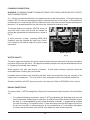
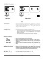
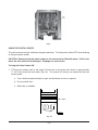
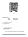
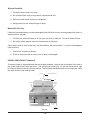
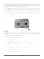
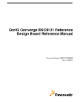
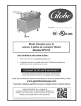
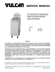
INSTALLATION &
OPERATION MANUAL
GPC SERIES GAS PASTA COOKERS
MODELS
GPC12
GPC12S
ML-126881
ML-126883
For additional information on Vulcan-Hart or to locate an authorized parts
and service provider in your area, visit our website at www.vulcanhart.com
VULCAN-HART
DIVISION OF ITW FOOD EQUIPMENT GROUP, LLC
P.O. BOX 696, LOUISVILLE, KY 40201-0696
TEL. (502) 778-2791
F-31173 Rev. A (02-04)
IMPORTANT FOR YOUR SAFETY
THIS MANUAL HAS BEEN PREPARED FOR PERSONNEL QUALIFIED TO INSTALL GAS
EQUIPMENT, WHO SHOULD PERFORM THE INITIAL FIELD START-UP AND
ADJUSTMENTS OF THE EQUIPMENT COVERED BY THIS MANUAL.
POST IN A PROMINENT LOCATION THE INSTRUCTIONS TO BE FOLLOWED IN THE
EVENT THE SMELL OF GAS IS DETECTED. THIS INFORMATION CAN BE OBTAINED
FROM THE LOCAL GAS SUPPLIER.
IMPORTANT
IN THE EVENT A GAS ODOR IS DETECTED, SHUT
DOWN UNITS AT MAIN SHUTOFF VALVE AND
CONTACT THE LOCAL GAS COMPANY OR GAS
SUPPLIER FOR SERVICE.
FOR YOUR SAFETY
DO NOT STORE OR USE GASOLINE OR OTHER
FLAMMABLE VAPORS OR LIQUIDS IN THE
VICINITY OF THIS OR ANY OTHER APPLIANCE.
WARNING
IMPROPER INSTALLATION, ADJUSTMENT,
ALTERATION OR MODIFICATION, SERVICE OR
MAINTENANCE CAN CAUSE PROPERTY
DAMAGE, INJURY OR DEATH. READ THE
INSTALLATION, OPERATING AND MAINTENANCE
INSTRUCTIONS THOROUGHLY BEFORE
INSTALLING OR SERVICING THIS EQUIPMENT.
IN THE EVENT OF A POWER FAILURE, DO NOT
ATTEMPT TO OPERATE THIS DEVICE.
–2–
TABLE OF CONTENTS
GENERAL . . . . . . . . . . . . . . . . . . . . . . . . . . . . . . . . . . . . . . . . . . . . . . . . . . . . . . . . . . . . . . . . . . . . . 4
INSTALLATION . . . . . . . . . . . . . . . . . . . . . . . . . . . . . . . . . . . . . . . . . . . . . . . . . . . . . . . . . . . . . . . . . 5
Unpacking . . . . . . . . . . . . . . . . . . . . . . . . . . . . . . . . . . . . . . . . . . . . . . . . . . . . . . . . . . . . . . . . 5
Location . . . . . . . . . . . . . . . . . . . . . . . . . . . . . . . . . . . . . . . . . . . . . . . . . . . . . . . . . . . . . . . . . 5
Installation Codes and Standards . . . . . . . . . . . . . . . . . . . . . . . . . . . . . . . . . . . . . . . . . . . . . 6
Assembly . . . . . . . . . . . . . . . . . . . . . . . . . . . . . . . . . . . . . . . . . . . . . . . . . . . . . . . . . . . . . . . . 6
Gas Connections . . . . . . . . . . . . . . . . . . . . . . . . . . . . . . . . . . . . . . . . . . . . . . . . . . . . . . . . . . 8
Gas Pressures and Orifices . . . . . . . . . . . . . . . . . . . . . . . . . . . . . . . . . . . . . . . . . . . . . . . . . 8
Testing the Gas Supply System . . . . . . . . . . . . . . . . . . . . . . . . . . . . . . . . . . . . . . . . . . . . . . 8
Leveling the Pasta Cooker . . . . . . . . . . . . . . . . . . . . . . . . . . . . . . . . . . . . . . . . . . . . . . . . . . 8
Flue Connections . . . . . . . . . . . . . . . . . . . . . . . . . . . . . . . . . . . . . . . . . . . . . . . . . . . . . . . . . . 9
Electrical Connections . . . . . . . . . . . . . . . . . . . . . . . . . . . . . . . . . . . . . . . . . . . . . . . . . . . . . . 9
Plumbing Connections . . . . . . . . . . . . . . . . . . . . . . . . . . . . . . . . . . . . . . . . . . . . . . . . . . . . . 10
Water Quality . . . . . . . . . . . . . . . . . . . . . . . . . . . . . . . . . . . . . . . . . . . . . . . . . . . . . . . . . . . . 10
Drain Connections . . . . . . . . . . . . . . . . . . . . . . . . . . . . . . . . . . . . . . . . . . . . . . . . . . . . . . . . 10
OPERATION . . . . . . . . . . . . . . . . . . . . . . . . . . . . . . . . . . . . . . . . . . . . . . . . . . . . . . . . . . . . . . . . . . 11
Before First Use . . . . . . . . . . . . . . . . . . . . . . . . . . . . . . . . . . . . . . . . . . . . . . . . . . . . . . . . . . 11
Controls . . . . . . . . . . . . . . . . . . . . . . . . . . . . . . . . . . . . . . . . . . . . . . . . . . . . . . . . . . . . . . . . 12
Using the Pasta Cooker . . . . . . . . . . . . . . . . . . . . . . . . . . . . . . . . . . . . . . . . . . . . . . . . . . . . 13
Swivel Head Faucet (Optional) . . . . . . . . . . . . . . . . . . . . . . . . . . . . . . . . . . . . . . . . . . . . . . 16
High Limit Device . . . . . . . . . . . . . . . . . . . . . . . . . . . . . . . . . . . . . . . . . . . . . . . . . . . . . . . . . 17
Overflow/Skim Port . . . . . . . . . . . . . . . . . . . . . . . . . . . . . . . . . . . . . . . . . . . . . . . . . . . . . . . 17
Cleaning . . . . . . . . . . . . . . . . . . . . . . . . . . . . . . . . . . . . . . . . . . . . . . . . . . . . . . . . . . . . . . . . 18
MAINTENANCE . . . . . . . . . . . . . . . . . . . . . . . . . . . . . . . . . . . . . . . . . . . . . . . . . . . . . . . . . . . . . . . . 20
Lubrication . . . . . . . . . . . . . . . . . . . . . . . . . . . . . . . . . . . . . . . . . . . . . . . . . . . . . . . . . . . . . . 20
Vent . . . . . . . . . . . . . . . . . . . . . . . . . . . . . . . . . . . . . . . . . . . . . . . . . . . . . . . . . . . . . . . . . . . . 20
Deliming . . . . . . . . . . . . . . . . . . . . . . . . . . . . . . . . . . . . . . . . . . . . . . . . . . . . . . . . . . . . . . . . 20
Service and Parts Information . . . . . . . . . . . . . . . . . . . . . . . . . . . . . . . . . . . . . . . . . . . . . . . 20
–3–
Installation, Operation and Care of
MODEL GPC SERIES GAS PASTA COOKER
KEEP THESE INSTRUCTIONS FOR FUTURE USE
GENERAL
Your Vulcan Gas Pasta Cooker is produced with quality workmanship and material. Proper installation,
usage and maintenance of your pasta cooker will result in many years of satisfactory performance.
It is suggested that you thoroughly read this entire manual and carefully follow all of the instructions
provided.
Each gas burner tube has 30,000 BTU input rating.
Model GPC12S is equipped with a chill tank (no burners) which is plumbed to both hot and cold water.
The chill tank is used for cooling pasta quickly. It is the same width as the pasta cooker.
Model
No. Tubes
BTU Input
Width
GPC12
3
90,000
151/2" (394 mm)
GPC12S
3
90,000
31" (787 mm)
Standard Features include:
• stainless steel tank, sides, door, and flue wrap
• mechanical thermostat
• electronic ignition
Model GPC12S is equipped with a foam zone overflow strainer. All models are equipped with a basket
hanger.
Optional accessories for all models include a basket hanger and stainless steel legs.
Optional accessories for only Model GPC12S include a stainless steel vat cover/tray, and a faucet
assembly.
The retherm basket with portion cups allows reheating of 12 servings at a time. The portion cups hold
a serving-size portion.
Accessories Factory Installable
(Must be requested at the time the original cooker is ordered.)
Basketlift
Cooker/Chill Tank Combo
–4–
Accessories Field Installable
Casters
Bulk Single Cook Basket
Retherm Basket
Portion Cups (set of 12)
Retherm Basket with cups
Round Angel Hair Pasta Baskets (set of 6)
Bulk Single Angel Hair Pasta Basket
S/S Vat Cover/Tray (Cooker/Chill Tank Combo Only)
Spray Assembly (Cooker/Chill Tank Combo Only)
INSTALLATION
Before installing, verify that the type of gas supply (natural or propane) and electrical service agree with
the specifications on the rating plate which is located on the inside of the door panel. If the supply and
equipment requirements do not agree, contact your dealer or Vulcan-Hart immediately.
UNPACKING
Immediately after unpacking, check for possible shipping damage. If the pasta cooker is found to be
damaged, save the packaging material and contact the carrier within 15 days of delivery.
Do not use the door or its handle to lift or move the pasta cooker.
For pasta cookers shipped on a pallet: Before removing the cooker from the pallet, assemble
casters or legs (see ASSEMBLY in this manual).
The pasta cooker is shipped without the swivel head attached. Look for the swivel head in the tank of
the cooker and screw it onto the faucet before hooking up the water.
LOCATION
Do not install pasta cooker next to a deep fat fryer because a splash-over of water into the hot oil may
cause a flash fire.
The equipment must be kept free and clear of combustible substances.
The pasta cooker, when installed, must have minimum clearance from combustible construction of 6"
(152 mm) from the sides and 6" (152 mm) from the rear. Clearance requirement from non-combustible
construction is 0" at the sides and rear. The pasta cooker may be installed on combustible floors.
The installation location must allow adequate clearances for servicing and proper operation.
A minimum front clearance of 36" (914 mm) is required.
The pasta cooker must be installed so that the flow of combustion and ventilation air will not be
obstructed. Adequate clearance for air openings into the combustion chamber must be provided.
Make sure there is an adequate supply of air in the room suitable for the amount of combustion gas
feeding the burners.
Do not permit fans to blow directly at the pasta cooker. Avoid open windows next to the pasta cooker.
Avoid wall-type fans which create air cross currents within the room.
–5–
INSTALLATION CODES AND STANDARDS
Your Vulcan-Hart gas pasta cooker must be installed in accordance with:
In the United States of America:
1. State and local codes.
2. National Fuel Gas Code, ANSI-Z223.1 (latest edition), available from the American Gas Association,
Inc., 1515 Wilson Blvd., Arlington, VA 22209.
3. National Electrical Code ANSI/NFPA-70 (latest edition). Copies may be obtained from the National
Fire Protection Association, Batterymarch Park, Quincy, MA 02269.
In Canada:
1. Local codes.
2. CAN/CGA-B149.1 (latest edition) Natural Gas Installation Code.
3. CAN/CGA-B149.2 (latest edition) Propane Installation Code, available from the Canadian Standards
Association, 178 Rexdale Blvd., Etobicoke, Ontario, Canada M9W 1R3.
4. Canadian Electric Code, CSA Standard C22.2 No.3 (latest edition). Copies may be obtained from
The Canadian Standards Association, 178 Rexdale Blvd., Etobicoke, Ontario, Canada M9W 1R3.
ASSEMBLY
The cooker must be restrained to prevent tipping when installed in order to avoid the splashing of hot
liquid. The means of restraint may be the manner of installation, such as connection to a battery of
appliances or installing the cooker in an alcove, or by separate means, such as adequate ties.
Legs
1. Position the pasta cooker in an open space near the final installation area.
2. Tilt pasta cooker on its side. Be careful not to scratch the finish.
3. Thread legs into mounting holes provided on the bottom of the pasta cooker by screwing in a
clockwise rotation until tightened.
4. Carefully raise pasta cooker to its normal position and place it in the installing location.
–6–
Casters
1. Position the pasta cooker in an open space near the final installation area.
2. Tilt pasta cooker on its side. Be careful not to scratch the finish.
3. Thread casters into mounting holes provided on the bottom of the pasta cooker by screwing in a
clockwise rotation until tightened.
4. Carefully raise pasta cooker to its normal position and place it in the installing location.
NOTICE: When the pasta cooker is mounted on casters, it must be installed with the casters supplied,
a connector (not supplied by Vulcan-Hart) complying with either ANSI Z21.69 (latest edition) or CAN/
CGA-6.16 (latest edition), and a quick disconnect device complying with either ANSI Z21.41 (latest
edition) or CAN1-6.9 (latest edition). It must also be installed with restraining means to guard against
transmission of strain to the connector, as specified in the appliance manufacturer's instructions.
Attach the restraining device at the rear of the oven. (Fig. 1).
Provide a gas line strain relief to limit movement of the pasta cooker without depending on the
connector and any quick-disconnect device or its associated piping to limit the pasta cooker's
movement. Attach the strain relief to the rear of the pasta cooker (Fig. 1).
Should it be necessary to disconnect the gas line strain relief, turn off the gas supply before
disconnection. Reconnect this restraint before turning the gas supply on and returning the pasta
cooker to its installation position.
STRAIN RELIEF
FITTING FOR GAS LINE
THIS SIDE ONLY.
(Strain relief fitting
supplied by Vulcan-Hart.
Chain to be supplied by
others.)
PL-51493
Fig. 1
Instructions for installing casters to the pasta cooker are included with the casters. Pasta cooker/chill
tank combination units are shipped with legs or casters already assembled.
–7–
GAS CONNECTIONS
CAUTION: Gas supply connections and any pipe joint compound used must be resistant to the
action of propane gases.
Codes require that a gas shutoff valve be installed in the gas line ahead of the pasta cooker.
Connect gas supply to the pasta cooker. The gas inlet is located at the rear of the pasta cooker on the
lower right when facing the rear of the machine.
The gas supply line must be at least the equivalent of 1/2" (13 mm) iron pipe. If using the optional quickdisconnect flex hose, 3/4" (19 mm) iron pipe must be used unless 3/4" to 1/2" (19 to 13 mm) reducing fittings
are used. Make sure the pipes are clean and free of obstructions, dirt, and piping compound.
WARNING: PRIOR TO LIGHTING, CHECK ALL JOINTS IN THE GAS SUPPLY LINE FOR LEAKS.
USE SOAP AND WATER SOLUTION. DO NOT USE AN OPEN FLAME.
After piping has been checked for leaks, all piping receiving gas should be fully purged to remove air.
GAS PRESSURES AND ORIFICES
The standard orifices are set at 4" W.C. (Water Column) (1 kPa) manifold pressure for natural gas and
10" W.C. (Water Column) (2.5 kPa) manifold pressure for propane gas. A pressure regulator is
supplied as part of the gas control valve.
TESTING THE GAS SUPPLY SYSTEM
When test pressures exceed 1/2 psig (3.45 kPa), the pasta cooker and its individual shutoff valve must
be disconnected from the gas supply piping system.
When test pressures are 1/2 psig (3.45 kPa) or less, the pasta cooker must be isolated from the gas
supply system by closing its individual manual shutoff valve.
LEVELING THE PASTA COOKER
Once gas connections have been made:
1. Place a spirit level on top of the pasta cooker.
2. Adjust the legs or casters to ensure that the pasta cooker is level front-to-back and side-to-side
in the final installed position.
Adjust casters:
1. Loosen the set screws in the caster extension.
2. Adjust the height.
3. Tighten the set screws.
–8–
FLUE CONNECTIONS
The pasta cooker must be located under a hood which has an adequate connection to an exhaust duct.
The hood must extend 6" (152.4 mm) beyond the sides of the pasta cooker.
Adequate ventilation must be provided and must comply with NFPA Standard #96 (latest edition), and
with local codes.
Clearance above the pasta cooker should be adequate for products of combustion to be removed
efficiently. An 18" (457 mm) minimum clearance should be maintained between the flue vent and the
filters of the hood venting system.
Never make flue connections directly to the pasta cooker. DO NOT obstruct the flow of flue gases from
the flue duct located on the rear of the pasta cooker.
Adequate air should be provided in the kitchen to replace air taken out by the ventilating system. This
will prevent the pasta cooker from being affected by a reduced atmospheric pressure.
It is recommended that the flue gases be ventilated to the outside of the building through a ventilation
system installed by qualified personnel.
Information on the construction and installation of ventilating hoods may be obtained from the standard
for "Vapor Removal from Cooking Equipment," NFPA No. 96 (latest edition), available from the
National Fire Protection Association, Batterymarch Park, Quincy, MA 02269.
ELECTRICAL CONNECTIONS
WARNING: ELECTRICAL AND GROUNDING CONNECTIONS MUST COMPLY WITH THE NATIONAL
ELECTRICAL CODE AND/OR OTHER LOCAL CODES.
WARNING: APPLIANCES EQUIPPED WITH ELECTRICAL SUPPLY CORD(S) ARE PROVIDED
WITH A THREE-PRONG GROUNDING PLUG WHICH MUST BE CONNECTED TO A PROPERLY
GROUNDED RECEPTACLE. IF THE RECEPTACLE IS NOT THE PROPER GROUNDING TYPE,
CONTACT AN ELECTRICIAN. DO NOT REMOVE THE GROUNDING PRONG FROM THE PLUG.
The pasta cooker is equipped with a 120 Volt / 60 Hz. / 1 Phase cord and plug which requires only that
it be plugged into a properly grounded 120 volt receptacle.
Do not connect the pasta cooker to electrical supply until after gas connections have been made.
The wiring diagram is located on the inside of the door panel.
–9–
PLUMBING CONNECTIONS
WARNING: PLUMBING CONNECTIONS MUST COMPLY WITH APPLICABLE SANITARY, SAFETY
AND PLUMBING CODES.
A 3/4" (19 mm) male hose connection is provided at the rear of the pasta cooker. On single body pasta
cookers GPC12, the water connection hookup is located in the rear of the cooker, in the leg channel
of the base frame. Note that the GPC12 models have only a hot water valve on the front control panel;
therefore, it is recommended that the hot water rear connection hookup be used.
The double body pasta cookers GPC12S, have hot
and cold water valves and should be hooked up
utilizing the appropriate rear connections as shown in
Fig 2.
A water hammer arrestor (meeting ASSE-1010
Standard) must be supplied (by other than VulcanHart Company) in the water supply line at the service
connection.
PL-41145
MODEL GPC12S
Fig. 2
WATER QUALITY
The water supply connected to this pasta cooker should contain no more than 2.0 grains of hardness
per gallon with pH from 6.5 to 8.0. This degree of hardness and pH can easily be obtained with the use
of a properly maintained water softener.
Water supplies vary from one location to another. A local water treatment specialist should be
consulted before installing the pasta cooker.
Untreated water contains scale producing minerals which can precipitate onto the surfaces in the
cooker and its components. This can result in early component failure and reduced product life.
Strainers and filters will NOT remove minerals from the water. Refer to DELIMING in this manual.
DRAIN CONNECTIONS
The pasta cooker 1" NPT Discharge Drain Pipe must be connected to the floor drain of the installation
site.
1. For standard discharge connection, using 1" NPT pipe directing the discharge drain from the
front of the cooker straight down into the floor. An alternate rear drain diverter method may also
be used. It is recommended that when using the diverter method a 1" capped tee be installed
for ease of cleaning. This method entails 1" pipe and fittings from the discharge at the front of
the unit to a rear drain. It will be necessary to use a combination of 1" tee, elbows and nipples
to access the drain location (the installer must determine what will be required).
– 10 –
OPERATION
WARNING: HOT WATER AND PARTS CAN CAUSE BURNS. USE CARE WHEN OPERATING,
CLEANING AND SERVICING THE PASTA COOKER.
WARNING: SPILLING HOT/BOILING WATER CAN CAUSE SEVERE BURNS. DO NOT MOVE
PASTA COOKER WITHOUT DRAINING ALL WATER FROM THE TANK.
CAUTION: This pasta cooker is designed exclusively for use with water. NEVER add oil with
the intent of frying in this cooker. (Oil on partially cooked pasta is OK.)
BEFORE FIRST USE
Clean the Pasta Cooker
1. Use a non-corrosive, grease-dissolving commercial cleaner to clean the protective metal oils from
all surface parts and the tank interior.
2. Follow the cleaner manufacturer's directions.
CAUTION: Be careful not to disturb the thermostat and high limit capillaries (Fig. 6) when
cleaning down inside the tank.
3. Rinse thoroughly and drain by opening the drain valve accessible when the door is opened (Fig. 7).
4. Wipe tank completely dry with a soft clean cloth.
5. Clean all pasta cooker accessories.
6. Rinse all parts thoroughly after cleaning.
7. Wipe dry.
Thermostat
High Limit
Device
Overflow / Skim
Port
PL-40199-1
Fig. 6
Fig. 7
– 11 –
CONTROLS (Fig's. 8 & 9)
HIGH LIMIT
P
O
BOI L
ON
P
O
W
E
R
OFF
HOT
ON
HEATING
15 MIN. TIMER
0 1
2
3
15
4
14
5
13
6
12
7
11
10 9 8
ON
ON
OFF
OFF
OFF
TROUBLE
COLD
BOI L
MER
SIM
MER
SIM
W
E
R
HIGH LIMIT
HOT
ON
TROUBLE
OFF
HEATING
15 MIN. TIMER
PUSH TO
TIME
BASKET LIFT CONTROL
TIMED BASKETLIFT
OPTION
0 1
2
3
15
4
14
5
13
6
12
7
11
10 9 8
PUSH TO
TIME
BASKET LIFT CONTROL
PL-53524
TIMED BASKETLIFT
OPTION
Model GPC12 / GPC16
Model GPC12S / GPC16S
Fig. 8
THERMOSTAT
— Controls temperature of water in tank. Temperature at "simmer"
setting is approximately 190°F (88°C); burners will cycle on and off.
At "boil" setting, temperature is 212°F (100°C); the burners will
remain on 100% of the time.
POWER SWITCH
— Turns electric power to the pasta cooker on or off.
• ON position opens the combination gas valve which allows the
ignitor to light the pilot. This will happen every time the power
switch is turned on.
• OFF position shuts off all gas to the burners and pilot.
INDICATOR LIGHTS:
ON
TROUBLE
HEATING
HIGH LIMIT
— When lit, electric power to the machine is on.
— When lit, the electronic igniter has not been able to light the pilot.
— When lit, burners are supplying heat, warming water in tank per
thermostat.
— When lit, there is not enough water in the tank; system has shut
down.
MANUAL FILL VALVES
— Model GPC12 has one hot water fill valve. Model GPC12S has one
hot water fill valve, and one cold water fill valve on the chill tank. Turn
fill valves counterclockwise to open and clockwise to close.
GAS VALVE (Fig. 9)
— Turns gas supply to the pasta cooker on or off.
– 12 –
Fig. 9
USING THE PASTA COOKER
The tank warranty may be voided by improper operation. Turn the power switch OFF when draining
or filling the pasta cooker.
CAUTION: Before turning the pasta cooker on, the tank must be filled with water. If this is not
done, the tank walls can be damaged. Warpage can cause leaks.
Turning the Pasta Cooker ON
1. Fill the pasta cooker tank to the water fill level line on the back wall, which is approximately
5" (127 mm) above the tank tubes (Fig. 10). The manual fill valve(s) are located on the front
control panel.
a. Turn handle counterclockwise to open and clockwise to close to operate.
b. Do not overfill tank.
c. Add water as needed.
FILL LEVEL
PL-51431
Fig. 10
– 13 –
2. Connect the power cord to an appropriate grounded receptacle.
3. Turn the gas valve (located inside the cabinet door - see Fig. 9) to the ON position.
4. Push the power switch to the ON position. A "snapping" noise will be heard. This is the igniter
lighting the pilot.
•
If the pilot fails to light within 90 seconds, the ignition system will automatically shut down and
the TROUBLE light will illuminate.
a. Push the power switch to the OFF position.
b. Wait 5 minutes.
c. Repeat Steps 2 and 3.
•
If the pilot still fails to light, contact a qualified Vulcan-Hart service representative.
5. Make sure the tank is full of water.
6. Turn the thermostat control knob to the desired setting.
Turning the Pasta Cooker OFF
CAUTION: If you drain the tank at the end of the day, it is imperative that you turn off the pilot
by pushing the power switch to the OFF position.
1. Push the power switch to the OFF position.
2. Turn the gas valve to the OFF position to shut off all gas to the system.
Extended Shutdown
1. Push the power switch to the OFF position and unplug the pasta cooker.
2. Turn gas valve to OFF position.
3. Drain tank by opening the drain valve (Fig. 11) located inside the cabinet door.
– 14 –
Fig. 11
Cooking
Do not overfill basket.
Recommended capacities are:
Model
Pounds of Spaghetti*
GPC12 / GPC12S
7 (3 kg)
*Amounts of different pasta, such as rigatoni, tortellini, or shells, may vary.
1. Fill tank with hot water to correct level.
2. Turn thermostat to "BOIL."
3. Bring water to full rolling boil.
With Basketlift:
1. Turn the timer to the desired setting.
2. Set basket on basketlift arm.
3. Push button to lower.
•
•
The basketlift arm will automatically raise when time is up.
If you wish to raise the basketlift arm before time is up, turn the timer knob to zero.
– 15 –
Without Basketlift:
1. Carefully lower basket into water.
2. Stir product often using a long utensil and protective mitt.
3. Remove basket when cooking is completed.
4. Hang basket on rear basket hanger to drain.
Model GPC12S Only:
If desired, the cooked pasta may be submerged in the chill tank to arrest cooking and quickly lower its
temperature for storage.
1. Fill chill tank with cold water to fill line (you may wish to add ice). Do not fill above fill line.
2. Stir often to help quickly lower the temperature of the pasta.
Other foods, such as corn-on-the-cob, may be cooked in the pasta cooker. It must be submerged to
cook uniformly.
1. Place corn in bottom of basket.
2. Stack an empty basket on top of corn to keep it submerged.
SWIVEL HEAD FAUCET (Optional)
The pasta cooker is shipped without the swivel head attached. Look for the swivel head in the tank of
the cooker and screw it onto the faucet. The swivel head faucet (Fig. 12) can be moved left to right
for use over either the hot or cold tank section. The left faucet handle controls hot running water, while
the right controls cold running water.
SWIVEL HEAD FAUCET
HOT
COLD
RINSE
STATION
COOKER
COOKER CONTROLS
COOKER FILL
VALVE (HOT)
RINSE STATION
FILL VALVE
(COLD)
PL-41473-1
Fig. 12
– 16 –
HIGH LIMIT DEVICE
If the water level goes below the thermostat and high limit location (Fig. 13), the high limit will turn the
pasta cooker off and extinguish the pilot. DO NOT relight the pilot until the tank has been refilled with
water.
OVERFLOW/SKIM PORT
An overflow/skim port is provided at the front of the tank (Fig. 13) and a fill port spray nozzle is provided
at the right rear of the tank just above the fill line (Fig. 14).
Thermostat
High Limit
Device
Overflow / Skim
Port
PL-40199-1
Fig. 13
FILL PORT SPRAY NOZZLE
FILL LINE
PL-41474-1
Fig. 14
The overflow/skim port serves two functions:
1. Allows operator to skim foam and starch debris from the product while cooking and also while
filling with fresh water.
2. Keeps the tank from overflowing during filling.
– 17 –
The fill port spray nozzle allows the operator to see the tank filling with water. The fill port spray nozzle
also forces the foam and starch debris over to the skim hole where the operator can skim off starches
and any unwanted debris while the tank is filling with fresh water.
To start filling the cooker tank, turn the left (hot) black manual fill valve handle on the front of the control
panel counterclockwise to the open position. To fill the rinse station side, use the right (cold) black
manual fill valve handle. Water will begin to fill into the tank through the fill port spray nozzle.
Note that the GPC12 will have only one valve handle for hot water fill of the cooker. The GPC12S will
have a hot and a cold valve handle (Fig. 15). The left handle of the GPC12S controls hot water flow
to the cooker and the right handle controls cold water flow to the rinse station. To stop flow and close
valve(s), turn handle(s) clockwise.
Be sure proper water level is maintained. Add water if necessary.
COLD WATER
FILL VALVE
TO RINSE STATION
HOT WATER
FILL VALVE
TO COOKER
PL-41475-1
Fig. 15
CLEANING
WARNING: UNPLUG THE PASTA COOKER AND TURN THE GAS VALVE OFF BEFORE CLEANING.
1. Clean the tank daily with a mild detergent and water.
•
DO NOT use "Dawn" dish detergent.
a. Rinse thoroughly.
b. Wipe dry with a soft clean cloth.
CAUTION: Be careful not to disturb (crimp or bend) the high limit or thermostat
capillaries (see Fig. 13).
2. Wash all exterior surfaces at least once daily.
a. Use a cloth with warm water and a mild soap or detergent.
b. Rinse thoroughly
c. Wipe dry with a soft clean cloth.
– 18 –
3. Make sure drains (tank and overflow/skim) are unobstructed. Dried cooked pasta can clog
drains.
4. Clean-out Brush
•
The clean-out brush is used to clean the space at the rear section of the battery between the
cooker and the rinse station.
a. Insert the brush into the opening and run brush up and down along the opening to remove any
debris that may have settled in this area (Fig. 17).
b. The brush can also be used on the front of the cooker for clean-out between the two control panel
plates.
PL-41476
Fig. 17
– 19 –
MAINTENANCE
WARNING: HOT WATER AND PARTS CAN CAUSE BURNS. USE CARE WHEN OPERATING,
CLEANING AND SERVICING THE PASTA COOKER.
WARNING: SPILLING HOT/BOILING WATER CAN CAUSE SEVERE BURNS. DO NOT MOVE
PASTA COOKER WITHOUT DRAINING ALL WATER FROM THE TANK.
LUBRICATION
Motors used on basketlift are permanently lubricated.
VENT
Annually, when pasta cooker is cool, check the flue and clear any obstructions.
DELIMING
The pasta cooker MUST be delimed periodically (depending upon usage, every 3-4 weeks). Follow the
deliming agent manufacturer's instructions. Rinse thoroughly at least 3 times before using pasta
cooker.
SERVICE AND PARTS INFORMATION
To obtain service and parts information concerning the pasta cooker, contact the Vulcan-Hart Service
Depot in your area (refer to listing supplied with the pasta cooker or visit our website at
www.VulcanHart.com).
F-31173 Rev. A (02-04)
– 20 –
PRINTED IN U.S.A.