1
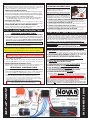
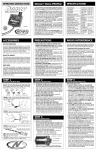
BASIC SET-UP GUIDE –- pulse V2 ESC
• Download “ESC Track Guide” from our web site for Proper Gearing & Custom Programming • Read All Instructions Before Use •
PRECAUTIONS
WATER & ELECTRONICS DON’T MIX!
Allowing water, moisture or other foreign materials to get inside ESC will void warranty.
MUST BE 14 YEARS OR OLDER TO OPERATE
Strict adult supervision is required for use by children under 14 years of age.
THERMAL OVERLOAD PROTECTION IS TURNED ON
#55-1756-2 Rev.2
2-2015
SPECIFICATIONS
Input Voltage.................................................................. 1S-2S LiPo cells, 4-6 NiMH cells
Motor Limit........................Any 540-size brushless; 4.5T & higher 550-size (any 380-size)
ESC Footprint & Height......................... 1.16” x 1.47” x 0.97”H (29.5 x 37.3 x 24.6mm)
ESC Weight (w/o wires).............................................................. 1.39 ounce (39.4 grams)
B.E.C. Voltage/Current (built-in).................................................. 6.0 volts DC / 5.0 amps
Power Wire (Battery/Motor)......................................................... 12G Super-Flex Silicone
On-Resistance.................................................. 0.0004ohm per phase @25°C trans.temp.
The Pulse V2 Brushless Racing ESC features Novak’s exclusive Super-TunerTM programming
interface, X-Drive, and Dynamic Timing Advance plus Xtra-Timing for insane top speeds.
The Pulse V2 is also fully-compatible with the Airtronics M12 transmitter and supports its
super-high speed operation with SSR receivers (details in the ‘One-Touch Programming’ section).
•This ‘Basic Set-Up Guide’ will get your Pulse V2 installed and adjusted to your transmitter •
When ready for complete ESC programming, the ‘Pulse V2 Track Guide’ is available in
the Downloads section of our web site (www.teamnovak.com), where it can be viewed or
printed and will guide you through all of the Super-Tuner’s adjustable parameters.
(Please contact our Customer Service if you don’t have internet access or have trouble viewing the ESC Track Guide)
Thermal overload circuitry is ACTIVE -- Heavy BEC loading may trigger protective circuitry!
SENSOR-BASED BRUSHLESS MOTORS ONLY
Designed for use with any 540-size (or 4.5T or higher 550-size) sensor-based brushless motors.
NEVER USE SCHOTTKY DIODES WITH BRUSHLESS ESCs!
DO NOT FREE REV OR OPERATE WITHOUT LOAD!
This includes running the motor without a pinion or holding the car in the air and
running the motor at or close to full power. Free revving will void the warranty!
1S-2S LiPo OR 4-6 NiMH CELLS ONLY
NEVER exceed 2S LiPo for vehicle’s main battery & be sure Voltage Cut-Off option is ON.
NEVER exceed 6-cell NiCd/NiMH (1.2VDC/cell), & disable Voltage Cut-Off Circuitry.
GOOD QUALITY RADIO & LiPo BATTERIES SUGGESTED
Undesirable radio noise may occur when using lower quality radio systems. 2.4GHz radio
system use is best; high quality FM system is acceptable; AM systems are NOT recommended.
LiPo’s that can’t supply the required amperage can damage electronics & voids warranty.
UNPLUG BATTERY WHEN NOT IN USE & SWITCH ESC OFF
Always disconnect the battery from ESC to avoid short circuits and possible fire hazard.
ALWAYS SWITCH OFF ESC BEFORE CONNECTING BATTERY
If battery is connected with ESC switch in ON position, serious damage can occur.
DON’T CHANGE WIRE COLORS or BUNDLE WIRES TOGETHER
Reverse-voltage connection damages ESC & voids warranty. Power wires emit RF noise.
DISCONNECT MOTOR BEFORE BINDING or ONE-TOUCH
ACCESSORIES
Motor may receive full throttle signal if connected to ESC & damage or injury can occur.
PLUG-IN INPUT SIGNAL HARNESS (JST-JST) [Novak kits #5315 & #5320]
Input signal harness with JST plug on both ends--4.5” (#5315), 9” (#5320).
BRUSHLESS MOTOR CONNECTOR WIRE SET [Novak kit #5332]
Flexible 14GA wire with gold-plated connectors for low-resistance connections.
BRUSHLESS SENSOR HARNESSES [Novak kit #5351-#5353]
Shielded sensor harness protects sensor wires--4” (#5351), 6” (#5352), 9” (#5353).
5-AMP UNIVERSAL BEC (2S) [Novak kit #5465]
Supplies 6.0V / 5A of power to receiver & servo for extra performance under heavy loads.
1S LiPo BOOSTER MODULE [Novak kit #5477]
Supplies 6V/3A to receiver & servo for optimal performance. For 1S racing & 2.4GHz.
SUPER-FLEX SILICONE 14GA WIRE SET [Novak kit #5508]
Two each of 9” length black, red, blue, yellow, and orange 14GA power wire.
SUPER-FLEX SILICONE 12GA POWER WIRE [Novak kit #5512]
Three feet each of black, red, and blue ultra low-resistance12GA power wire.
ESC POWER SWITCH HARNESS [Novak kit #5600]
Includes replacement ON/OFF Power Switch with stripped & tinned wire harness.
GLITCH BUSTER CAPACITOR [Novak kit #5626] *HIGHLY RECOMMENDED*
Provides reserve power to receiver during extreme loading from power hungry servos.
25x25x10mm COOLING FANS [Novak kits #5647 & #5651]
Cooling fans with JST power plug. Single fan (#5647), 2-pack of fans (#5651).
TRIPLE-POWERCAP BLOCK MODULE --2S [Novak kit #5690] *OPTIONAL*
Suppressor technology PowerCap module for improved efficiency with timing advance ESCs.
POWER CONNECTORS–3.5mm & 4mm [Novak kit #5731 & #5741]
Low-Loss bullet connectors generate dozens of wiring routing and installation options.
LEAD-FREE SILVER SOLDER [Novak kit #5831-#5833]
3% Silver solder for high-conductivity--6gr (#5831), 15gr (#5832), 100gr (#5833).
MOUNTING TAPE 25x35mm [Novak kit #5840 & #5841]
Cushioned, double-sided tape for mounting electronics--10pc (#5840), 100pc (#5841).
HEAT SHRINK TUBING [Novak kit #5850 & #5851]
6” long heat shrink tubing in six sizes: 1/16” - 3/8”--6pc kit (#5850), 24pc kit (#5851).
Turn on transmitter power first so you will have control of vehicle when you turn it on.
TRANSMITTER ON FIRST
NO REVERSE VOLTAGE!
Reverse battery connection will damage ESC immediately & will void the warranty!
Insulate exposed wiring with heat shrink tubing or electrical tape to prevent short circuits.
GLITCH BUSTER SUGGESTED / BUILT-IN POWERCAPS
The built-in PowerCaps on ESC MUST be retained to avoid high ESC temperatures &
possible damage. Use of the included Glitch Buster helps with heavy BEC loading.
NO CA GLUE
CA glue or fumes can damage internal components of ESC & cause premature failure.
VOLTAGE cUt-OFF circuitry
When active, the built-in Smart-Stop Auto-Detect Voltage Cut-Off Circuitry lets you
safely use 2S Lithium Polymer (LiPo) battery packs by cutting off the speed control’s
throttle output when the battery’s critical safety voltage is reached.
This circuitry monitors battery voltage and automatically selects a 2S cut-off voltage
value when using a 2S battery pack. When the ESC detects that the critical safety
voltage value will soon be reached, it begins cutting back the throttle output level
to prevent the battery’s voltage from reaching the a level that results in cell damage.
When the critical voltage is reached, the throttle output to the motor gets
completely shut down to keep the voltage from dropping further. (Red & Yellow
LEDs will alternately flash & you still have steering control).
Re-charge battery after Smart-Stop circuitry shuts off throttle
Even though the pack’s voltage will rise (after a short resting period) to a level high enough
to run motor again, reaching critical voltage too many times will damage cells.
DO NOT RUN VEHICLE AFTER SMART-STOP HAS SHUT DOWN THROTTLE OUTPUT!
ONE-YEAR product warranty
This Brushless ESC is guaranteed to be free from defects in materials or workmanship for a period of one year from
original purchase date (verified by dated, itemized sales receipt). Warranty does not cover incorrect installation,
components worn by use, damage to case or exposed circuit boards, damage from using more than 6 cells (1.2
volts DC/cell) or more than 2 LiPo cells input voltage, damage resulting from using LiPo batteries without SmartStop voltage cut-off circuitry active, using insufficient LiPo batteries that cannot supply the amperage required
by this system, damage resulting from thermal overload or excessive BEC loading or disabling Thermal Protection
Circuitry, overheating solder tabs, cross-connection of battery/motor power wires, reverse voltage application,
improper use or installation of external BEC, damage from incorrect installation of FET servo or receiver battery
pack, damage due to free revving motor, damage due to short-circuiting motor or using a non-Novak motor or
a non-sensored motor, removal of facotry-installed PowerCaps, incorrect installation of a PowerCap or operating
ESC with damaged PowerCaps, using a Schottky diode, splices to input, ON/OFF switch, or sensor harnesses,
replacing power wires with all same color wires, damage from excessive force when using the One-Touch/SET
button or from disassembling case, tampering with internal electronics, allowing water, moisture, or any other
foreign material to enter ESC or get onto the PC board, incorrect installation/wiring of input plug plastic, allowing
exposed wiring or solder tabs to short-circuit, or any damage caused by a crash, flooding, or natural disaster.
Because Novak has no control over connection & use of ESC or other related electronics, no liability may
be assumed nor will be accepted for any damage resulting from the use of this product. Every Novak ESC
& motor is thoroughly tested & cycled before leaving our facility and is, therefore, considered operational.
By the act of connecting/operating ESC, user accepts all resulting liability. In no case shall our liability
exceed the product’s original cost. We reserve the right to modify warranty provisions without notice.
This product is not intended for use by children under 14 years of age without the strict supervision of an
adult. Use of this product in an uncontrolled manner may result in physical damage or injuries—take extra
care when operating any remote control vehicle. Melted ESCs/motors are not covered by the warranty.
Designed by Novak R/C, Inc. in California and assembled with globally sourced components.
©2015 Novak R/C, Inc. • All Rights Reserved • No part of these instructions may be reproduced without
the written permission of Novak R/C, Inc. Pulse V2 Brushless ESC, Super-Tuner programming interface,
Xtra-Timing, Hall Sensor Test, & One-Touch Set-Up are all trademarks of Novak R/C, Inc.
With the Voltage Cut-Off turned ON & using NiCd/NiMH cells, the ESC’s throttle output will
shut off very early into the run--Change the Cut-Off Circuitry mode to OFF to use these batteries.
See CUSTOM PROGRAMMING section on ESC Track Guide to properly adjust this setting.
RECEIVER PACK USAGE
NOVAK HIGHLY-RECOMMENDS the use of an external receiver battery pack
to supply power to the electronics when using very high-power servos, as these
servos put excessive load on the speed control’s internal BEC.
Using an external reciever pack will greatly increase life span of your
ESC, as this is a leading cause of speed control failure.
To use an External Receiver Battery Pack to Power the Electronics:
1. Plug the 5 cell (1.2 VDC/Cell) receiver battery pack into the battery slot (or any
open/unused channel) of the receiver.
2. Remove the red wire from ESC’s input receiver harness (insulate the red wire).
3. To turn the vehicle ON, switch the receiver pack’s power switch ON. Then, turn
the ESC’s power switch ON.
4. To turn vehicle OFF, turn ESC’s switch OFF, then turn receiver pack’s switch OFF.
step 1–mount esc
step 3–connect receiver
Mount the ESC so the power wires are as far away from other electronics as
possible, and will not interfere with the vehicle’s moving parts. Select a location with good airflow for cooling the ESC for efficient operation.
1.MOUNT SPEED CONTROL IN VEHICLE
Use the included double-sided tape to mount ESC in vehicle (do not use glue).
Avoid contact with side walls or chassis components to avoid vibration damage.
Be sure receiver & antenna are mounted as far from ESC, power wires, battery,
and servo as possible--These components all emit RF noise.
receiver connections
The ESC has a user-replaceable input harness
with the industry-standard connector on both
the ESC and receiver ends of it.
ESC works with all major brand’s new receivers
2.INSTALL ON/OFF SWITCH
Use included double-sided tape to mount switch where it will be easy to
access--select a place where it will not get damaged/switched OFF in a crash.
3.SECURE POWER WIRES TO AVOID VIBRATION DAMAGE
Use the included tie-wraps to secure the ESC’s power wires together or to
a point on the vehicle to prevent vibration damage.
step 2–connect motor/battery
Insert 3-pin plug on other end of receiver harness into Ch.2 (throttle) slot of receiver.
Press fan screws through 2 of the holes along one edge of the fan and into the 1st
gap of ESC heat sink fins. Plug fan connector onto ESC’s fan pins--note polarity.
4. CONNECT GLITCH BUSTER CAPACITOR TO RECEIVER
Insert connector of Glitch Buster into any open slot of receiver--note polarity.
STEP 4-one-touch programming
This ESC is compatible with standard rate radio systems and also the super-high
speed Airtronics M12 radio system operating in its SSR mode. ESC must first be
switched to the correct radio system mode before it will recognize the receiver and
allow the One-Touch Set-Up programming. ESC ships from Novak in the Standard
Rate Mode and is ready to program if this is what type of system you are using.
For standard rate systems, skip steps A-D below and simply follow Steps 1-8.
If installing ESC with an M12 radio system operating in SSR mode, follow Steps A-D
below to switch modes (refer to ESC Track Guide for detailed information), then complete
Steps 1-8 afterwards. (Steps A-D need only be done the 1st time)
MAKE SURE THE PINION/SPUR GEAR MESH IS NOT TOO TIGHT!
B.Tighten motor mounting screws–Avoid using excessive force that could
break screws or strip the threaded holes in motor.
With at least 2 of the Motor power wires disconnected & the ESC connected
to a charged battery pack, the receiver, & the motor’s sensor harness:
2.CHECK FOR PROPER GEARING DURING INITIAL RUNS
The brushless motor & ESC should NOT be hotter than 160°F after a 5 minute
run. Lower the gearing until both ESC & motor are under this temperature.
A.TURN ON THE SPEED CONTROL’S POWER
B. PRESS & HOLD ESC’S SET BUTTON until Red & Green status LEDs come on
You must continue holding button until you pass through all of the ESC’s
programming options. Release SET button once Red & Green status LEDs are lit.
C. SELECT PROPER RADIO SYSTEM MODE (2 LED flashes = Std / 1 flash = SSR)
Quick press & release the ESC’s SET button to change the selection.
3.CONNECT ESC’s MOTOR POWER PHASE WIRES TO MOTOR
Note: The motor power wires are all blue, therefore you must refer to the
phase markings stamped on the ESC’s case tub for proper wiring sequence.
A. Solder the speed control’s Phase ‘A’ silicone motor power wire to the
motor’s Phase “A” solder tab.
B. Solder the ESC’s Phase ‘B’ motor wire to the motor’s Phase “B” solder tab.
C. Solder the ESC’s Phase ‘C’ motor wire to the motor’s Phase “C” solder tab.
4.CONNECT MOTOR SENSOR HARNESS TO ESC
Insert the 6-pin connector of the motor’s sensor harness into ESC’s sensor
harness socket—connector is keyed and only inserts in one direction.
D.PRESS & HOLD ESC’S SET BUTTON TO STORE NEW SELECTION
1. WITH ESC OFF, TURN ON THE TRANSMITTER’S POWER
2. PRESS & HOLD ESC’S ONE-TOUCH/SET BUTTON
3. TURN ON THE SPEED CONTROL’S POWER
With transmitter at neutral (still pressing SET button), slide ESC’s switch to ON position.
Hold it there until green status LED turns solid green. (Motor won’t run during programming).
Hold it there until the green status LED blinks green.
4. CONTINUE HOLDING SET BUTTON UNTIL RED LED COMES ON
5. RELEASE SET BUTTON AS SOON AS RED LED TURNS ON
6. PULL TRANSMITTER THROTTLE TO FULL-ON POSITION
Battery connection
7. PUSH TRANSMITTER THROTTLE TO FULL-BRAKE/REVERSE
1.CONNECT ESC’S BATTERY WIRES OR CONNECTOR TO BATTERY PACK
Solder the ESC’s RED & BLACK battery power wires to a fully charged 1S-2S
LiPo, or 4-6 cell NiMH (1.2 VDC/cell) battery pack or to a connector.
8. RETURN TRANSMITTER THROTTLE TO NEUTRAL
To use battery connectors on the ESC, we suggest using low-loss high power
connectors like Dean’s Ultra Plug or the Novak Power Connector.
Red status LED will turn on solid, indicating ESC is at neutral and programming is
complete. White LED may also be on/blinking, indicating that Timing Advance is OFF (0%).
If transmitter settings are changed, One-Touch Set-Up must be repeated.
•Use polarized connectors. Reverse voltage will damage ESC & void warranty.
•Use a female connector on battery packs to avoid shorting of exposed contacts.
•Insulate all exposed wiring connection to avoid shorting.
Transmitter adjustments are not usually required to properly complete the programming
of the One-Touch set-up. If you are unable to successfully program the One-Touch set-up,
adjust your transmitter settings as listed in the “Transmitter Adjustments” section on the
Pulse Track Guide, then repeat the One-Touch Programming steps above.
NOTE: If using NiMH/NiCd batteries, the Voltage Cut-Off Circuitry
must be turned OFF (refer to the ESC Track Guide).
NOTE: ESC will NOT revert back to factory-default settings when the One-Touch set-up is
performed. Refer to ‘Data Reset’ in Custom Programming section of ESC Track Guide.
on-board
PowerCaps
Status
LEDs
19 Rancho Circle, Lake Forest, CA 92630 • 949-916-6044
Servo plugged into
steering ch. (#1)
Black power wire
Red power wire
(battery positive)
User-replaceable
input signal harness
(Ch.2)
Sensor
harness
Blue motor
power wire
(Phase C)
Battery
connector
(if used)
Battery pigtail -- Keep
connected to battery to
avoid reverse voltage!
Blue motor
power wire
(Phase A)
Sensor-based
brushless motor
*Battery pack, servo, and
receiver are not included.
(battery negative)
Set
button
Blue motor
power wire
(Phase B)
Battery pack
• 1S or 2S LiPo or 4-6 cell NiMH/NiCd •
www.teamnovak.com
set-up photo
Insert the 3-pin plug on one end of receiver input harness onto the receiver harness
3-pin header on the ESC. White wire goes on the right side pin as shown above.
3. INSTALL 25mm COOLING FAN ON ESC (OPTIONAL)
1.INSTALL PINION GEAR & ADJUST MOTOR FOR PROPER GEAR MESH
Tighten pinion’s set screw on flat of motor shaft. Align pinion & spur gears.
A. You NEED a small amount of play between the pinion and spur gear
(about thickness of a piece of paper)–check free play at several points around
spur gear to ensure a proper mesh (just in case gears are out of round).
Glitch Buster
plugged into any
open receiver slot
ON/OFF
2. CONNECT RECEIVER HARNESS TO RECEIVER
Motor connection
ESC
ON/OFF
Switch
rec. positive
(red wire)
switch
(very old receivers need wiring sequence changed in
plastic plug on receiver end--Damage may occur
rec.
Motor
negative
if sequence is incorrect) . For instructions on sensor
harness (black
wire)
connector
changing the wiring sequences, visit our web site.
1. CONNECT INPUT HARNESS TO RECEIVER HARNESS PINS ON ESC
Note: Mount antenna as close to receiver as possible--trail excess wire off top of
antenna mast (cutting/coiling excess wire reduces radio range--2.4GHz too).
Receiver
positive
fan wire
receiver signal
(white wire)