1
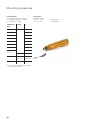
Encoders for
Servo Drives
November 2013
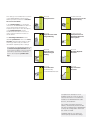
This catalog is not intended as an overview
of the HEIDENHAIN product program.
Rather it presents a selection of encoders
for use on servo drives.
Brochure
Rotary Encoders
Product Overview
Rotary Encoders for the
Elevator Industry
Produktübersicht
Drehgeber für die
Aufzugsindustrie
In the selection tables you will find an
overview of all HEIDENHAIN encoders for
use on electric drives and the most
important specifications. The descriptions
of the technical features contain
fundamental information on the use of
rotary, angular, and linear encoders on
electric drives.
The mounting information and the
detailed specifications refer to the rotary
encoders developed specifically for drive
technology. Other rotary encoders are
described in separate product catalogs.
Oktober 2007
Product Overview
Rotary Encoders for
Potentially Explosive
Atmospheres
Brochure
Angle Encoders with
Integral Bearing
Produktübersicht
Winkelmessgeräte
mit Eigenlagerung
Drehgeber
für explosionsgefährdete
Bereiche (ATEX)
Januar 2009
August 2013
You will find more detailed information on
the linear and angular encoders listed
in the selection tables, such as mounting
information, specifications and dimensions in the respective product catalogs.
Brochure
Angle Encoders
without Integral
Bearing
Brochure
Modular Magnetic
Encoders
Winkelmessgeräte
ohne Eigenlagerung
Magnetische
Einbau-Messgeräte
September 2011
September 2012
Brochure
Linear Encoders
For Numerically
Controlled Machine Tools
Längenmessgeräte
für gesteuerte
Werkzeugmaschinen
August 2012
Brochure
Exposed Linear
Encoders
Offene
Längenmessgeräte
März 2012
Comprehensive descriptions of all
available interfaces as well as general
electrical information is included in the
Interfaces for HEIDENHAIN Encoders
brochure, ID 1078628-xx.
This catalog supersedes all previous
editions, which thereby become invalid.
The basis for ordering from HEIDENHAIN
is always the catalog edition valid when
the contract is made.
Standards (ISO, EN, etc.) apply only
where explicitly stated in the catalog.
Contents
Overview
Explanation of the selection tables
6
Rotary encoders for integration in motors
8
Rotary encoders for mounting on motors
10
Rotary encoders and angle encoders for integrated and hollow-shaft motors
14
Linear encoders for linear drives
16
Technical features and mounting information
Rotary encoders and angle encoders for three-phase AC and DC motors
20
Linear encoders for linear drives
22
Safety-related position measuring systems
24
Measuring principles
26
Measuring accuracy
29
Mechanical designs, mounting and accessories
32
General mechanical information
39
Specifications
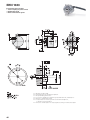
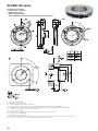
Rotary encoders with
integral bearing
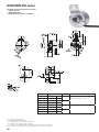
ECN/EQN 1100 series
44
ERN 1023
46
ERN 1123
48
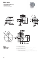
ECN/EQN 1300 series
50
ECN/EQN 400 series
52
ERN 1300 series
54
EQN/ERN 400 series
56
ERN 401 series
58
Rotary encoders without ECI/EQI 1100 series
integral bearing
ECI 1118
60
62
EBI 1135
64
ECI/EQI 1300 series EnDat01
66
ECI/EQI 1300 series EnDat22
68
ECI/EBI 100 series
70
ERO 1200 series
72
ERO 1400 series
74
Electrical connection
Interfaces
76
Cables and connecting elements
87
Diagnostic and testing equipment
92
Evaluation electronics
94
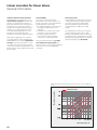
Encoders for servo drives
Controlling systems for servo drives
require measuring systems that provide
feedback for the position and speed
controllers and for electronic commutation.
The properties of encoders have decisive
influence on important motor qualities such
as:
• Positioning accuracy
• Speed stability
• Bandwidth, which determines drive
command-signal response and
disturbance rejection capability
• Power loss
• Size
• Noise emission
• Safety
Digital position and speed control
Rotary encoder (actual position value,
actual speed value,
commutation signal)
Mi
ii
Speed
calculation
ni
Ms
Position
controller
ns
is
Speed
controller
Decoupling
Current
controller
HEIDENHAIN offers the appropriate
solution for any of a wide range of
applications using both rotary and linear
motors:
• Incremental rotary encoders with and
without commutation tracks, absolute
rotary encoders
• Incremental and absolute angle
encoders
• Incremental and absolute linear
encoders
• Incremental modular encoders
Rotary encoder
4
Inverter
Overview
All the HEIDENHAIN encoders shown in
this catalog involve very little cost and
effort for the motor manufacturer to mount
and wire. Encoders for rotary motors are of
short overall length. Some encoders, due
to their special design, can perform
functions otherwise handled by safety
devices such as limit switches.
Motors for “digital” drive systems
(digital position and speed control)
Rotary encoder
Angle encoders
Linear encoders
5
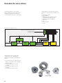
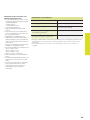
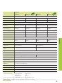
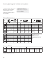
Explanation of the selection tables
The tables on the following pages list the encoders suited for
individual motor designs. The encoders are available with
dimensions and output signals to fit specific types of motors (DC
or AC).
Rotary encoders for mounting on motors
Rotary encoders for motors with forced ventilation are either built
onto the motor housing or integrated. As a result, they are
frequently exposed to the unfiltered forced-air stream of the motor
and must have a high degree of protection, such as IP 64 or better.
The permissible operating temperature seldom exceeds 100 °C.
In the selection table you will find:
• Rotary encoders with mounted stator couplings with high
natural frequency—virtually eliminating any limits on the
bandwidth of the drive
• Rotary encoders for separate shaft couplings, which are
particularly suited for insulated mounting
• Incremental rotary encoders with high quality sinusoidal
output signals for digital speed control
• Absolute rotary encoders with purely digital data transfer or
complementary sinusoidal incremental signals
• Incremental rotary encoders with TTL or HTL compatible
output signals
• Information on rotary encoders that are available as safetyrelated position encoders under the designation Functional
Safety .
For selection table see page 10
Rotary encoders for integration in motors
For motors without separate ventilation, the rotary encoder is built
into the motor housing. This configuration places no stringent
requirements on the encoder for a high degree of protection. The
operating temperature within the motor housing, however, can
reach 100 °C and higher.
In the selection table you will find
• Incremental rotary encoders for operating temperatures up to
120 °C, and absolute rotary encoders for operating temperatures
up to 115 °C
• Rotary encoders with mounted stator couplings with high
natural frequency—virtually eliminating any limits on the
bandwidth of the drive
• Incremental rotary encoders for digital speed control with
sinusoidal output signals of high quality—even at high
operating temperatures
• Absolute rotary encoders with purely digital data transfer or
complementary sinusoidal incremental signals
• Incremental rotary encoders with additional commutation
signal for synchronous motors
• Incremental rotary encoders with TTL-compatible output
signals
• Information on rotary encoders that are available as safetyrelated position encoders under the designation Functional
Safety .
For selection table see page 8
6
Rotary encoders, modular rotary encoders and angle
encoders for integrated and hollow-shaft motors
Rotary encoders and angle encoders for these motors have
hollow through shafts in order to allow supply lines, for example,
to be conducted through the motor shaft—and therefore through
the encoder. Depending on the conditions of the application, the
encoders must either feature IP 66 protection or—for example
with modular encoders using optical scanning—the machine must
be designed to protect them from contamination.
In the selection table you will find
• Angle encoders and modular encoders with the measuring
standard on a steel drum for shaft speeds up to 42 000 min–1
• Encoders with integral bearing, with stator coupling or modular
design
• Encoders with high quality absolute and/or incremental
output signals
• Encoders with good acceleration performance for a broad
bandwidth in the control loop
For selection table see page 14
Linear encoders for linear motors
Linear encoders on linear motors supply the actual value both for
the position controller and the velocity controller. They therefore
form the basis for the servo characteristics of a linear drive. The
linear encoders recommended for this application:
• Have low position deviation during acceleration in the measuring
direction
• Have high tolerance to acceleration and vibration in the lateral
direction
• Are designed for high velocities
• Provide absolute position information with purely digital data
transmission or high-quality sinusoidal incremental signals
Exposed linear encoders are characterized by:
• Higher accuracy grades
• Higher traversing speeds
• Contact-free scanning, i.e., no friction between scanning head
and scale
Exposed linear encoders are suited for applications in clean
environments, for example on measuring machines or production
equipment in the semiconductor industry.
For selection table see page 16
Sealed linear encoders are characterized by:
• A high degree of protection
• Simple installation
Sealed linear encoders are therefore ideal for applications in
environments with airborne liquids and particles, such as on
machine tools.
For selection table see page 18
7
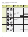
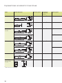
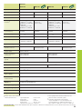
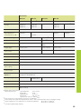
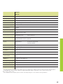
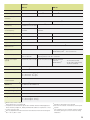
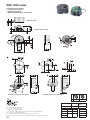
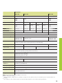
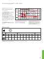
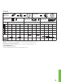
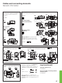
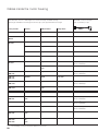
Selection guide
Rotary encoders for integration in motors
Protection: up to IP 40 (EN 60 529)
Series
Overall dimensions
Mechanically
permissible
speed
Natural freq.
of stator
connection
Maximum
operating
temperature
Voltage supply
j 1 000 Hz
115 °C
3.6 V to 14 V DC
i6 000 min
j 1 600 Hz
90 °C
–1
i15 000 min /
i12 000 min–1
j 1800 Hz
115 °C
Rotary encoders with integral bearing and mounted stator coupling
–1
i12 000 min
ECN/EQN/
ERN 1100
–1
ECN/EQN/
ERN 1300
–1
i15 000 min
3.6 V to 14 V DC
120 °C
5 V DC ± 0.5 V
ERN 1381/4096:
5 V DC ± 0.25 V
80 °C
(not with ERN)
5 V DC ± 0.5 V
5 V DC ± 0.25 V
Rotary encoders without integral bearing
–1
i15 000 min /
i12 000 min–1
ECI/EQI 1100
–
115 °C
5 V DC ± 0.25 V
3.6 V to 14 V DC
13 for EBI
EBI 1100
i15 000 min–1/
i12 000 min–1
ECI/EQI 1300
–
115 °C
4.75 V to 10 V DC
3.6 V to 14 V DC
–1
i6 000 min
–
115 °C
3.6 V to 14 V DC
ERO 1200
i25 000 min–1
–
100 °C
5 V DC ± 0.5 V
ERO 1400
i30 000 min–1
–
ECI 100
EBI 100
70 °C
5 V DC ± 0.5 V
5 V DC ± 0.25 V
5 V DC ± 0.5 V
1)
8
Functional Safety upon request
2)
after internal 5/10/20/25-fold interpolation
Signal periods
per revolution
Positions per
revolution
Distinguishable
revolutions
Interface
Model
More
information
512
8 192 (13 bits)
–/4 096
EnDat 2.2 / 01 with 1 VPP
ECN 1113 / EQN 1125
Page 44
–
8 388 608 (23 bits)
EnDat 2.2/22
ECN 1123/EQN 11351)
500 to 8 192
3 block commutation signals
TTL
ERN 1123
Page 48
512/2 048
8 192 (13 bits)
EnDat 2.2 / 01 with 1 VPP
ECN 1313/EQN 1325
Page 50
–
33 554 432 (25 bits)
EnDat 2.2/22
ECN 1325/EQN 13371)
1 024/2 048/4 096
–
TTL
ERN 1321
–/4 096
ERN 1326
3 block commutation signals
1 VPP
512/2 048/4 096
–
2 048
Z1 track for sine commutation
16
262 144 (18 bits)
–/4 096
–
32
ERN 1381
ERN 1387
EnDat 2.1 / 01 with 1 VPP
ECI 1118/EQI 1130
Page 60
EnDat 2.1 / 21
524 288 (19 bits)
–
EnDat 2.2 / 22
ECI 1118
Page 62
65 5363)
EnDat 2.2/22
EBI 1135
Page 64
–/ 4 096
EnDat 2.2 / 01 with 1 VPP
ECI 1319/EQI 13311)
Page 66
–
32
Page 68
EnDat 2.2/22
524 288 (19 bits)
–
–
EnDat 2.1 / 01 with 1 VPP
ECI 119
EnDat 2.2/22
EBI 135
TTL
ERO 1225
1 VPP
ERO 1285
TTL
ERO 1420
5 000 to 37 5002)
TTL
ERO 1470
512/1 000/1 024
1 VPP
ERO 1480
512/1 000/1 024
3)
Page 70
EnDat 2.2/22
65 5363)
1 024/2 048
Page 54
–
–
Page 72
Page 74
Multiturn function via battery-buffered revolution counter
9
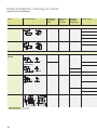
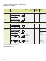
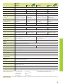
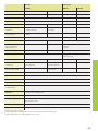
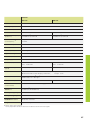
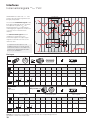
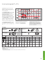
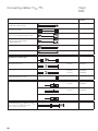
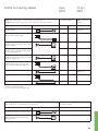
Rotary encoders for mounting on motors
Protection: up to IP 64 (EN 60 529)
Series
Overall dimensions
Mechanically
permissible
speed
Natural freq.
of stator
connection
Maximum
operating
temperature
Voltage supply
100 °C
5 V DC ± 0.25 V
Rotary encoders with integral bearing and mounted stator coupling
D i 30 mm:
i6 000 min–1
ECN/ERN 100
j 1 100 Hz
3.6 V to 5.25 V DC
D > 30 mm:
i4 000 min–1
ECN/EQN/ERN 400
i6 000 min–1
Stator coupling
With two shaft
clamps (only for
hollow through
shaft):
i12 000 min–1
Universal stator coupling
5 V DC ± 0.5 V
Stator coupling:
j 1 500 Hz
Universal stator
coupling:
j 1 400 Hz
85 °C
10 V to 30 V DC
100 °C
3.6 V to 14 V DC
5 V DC ± 0.5 V
10 V to 30 V DC
70 °C
ECN/EQN/ERN 400
–1
i15 000 min /
i12 000 min–1
Expanding ring coupling
i15 000 min–1
(not with ERN)
Expanding ring
coupling:
j 1800 Hz
Plane-surface
coupling:
j 400 Hz
100 °C
5 V DC ± 0.5 V
100 °C
3.6 V to 14 V DC
5 V DC ± 0.5 V
5 V DC ± 0.25 V
83.2
Plane-surface coupling
50.5
22
i12 000 min–1
ECN/EQN/ERN 1000
j 1 500 Hz
100 °C
3.6 V to 14 V DC
5 V DC ± 0.5 V
ERN 1023
70 °C
10 V to 30 V DC
5 V DC ± 0.25 V
100 °C
i6 000 min–1
1)
Functional Safety upon request
10
2)
j 1 600 Hz
after internal 5/10/20/25-fold interpolation
90 °C
5 V DC ± 0.5 V
Signal periods
per revolution
Positions
per revolution
Distinguishable
revolutions
Interface
Model
More
information
2 048
8 192 (13 bits)
–
EnDat 2.2 / 01 with 1 VPP
ECN 113
–
33 554 432 (25 bits)
EnDat 2.2/22
ECN 125
Catalog:
Rotary
Encoders
1 000 to 5 000
–
TTL/ 1 VPP
ERN 120/ERN 180
HTL
ERN 130
EnDat 2.2 / 01 1 VPP
ECN 413/EQN 425
512, 2 048
8 192 (13 bits)
–/4 096
–
33 554 432 (25 bits)
EnDat 2.2/22
ECN 425/EQN 437
250 to 5 000
–
TTL
ERN 420
HTL
ERN 430
TTL
ERN 460
1 VPP
ERN 480
EnDat 2.2 / 01 with 1 VPP
ECN 413/EQN 425
1 000 to 5 000
2 048
8 192 (13 bits)
–/4 096
–
33 554 432 (25 bits)
EnDat 2.2/22
ECN 425/EQN 4371)
1 024 to 5 000
–
TTL
ERN 421
2 048
Z1 track for sine commutation
512
8 192 (13 bits)
–
100 to 3 600
ECN 1013/EQN 1025
8 388 608 (23 bits)
EnDat 2.2/22
ECN 1023/EQN 1035
–
TTL/ 1 VPP
ERN 1020/ERN 1080
HTLs
ERN 1030
TTL
ERN 1070
5 000 to 36 0002)
Product
Information
ERN 487
EnDat 2.2 / 01 with 1 VPP
–/4 096
Page 52
Catalog:
Rotary
Encoders
512, 2 048
Z1 track for sine commutation
1 VPP
ERN 1085
Product
Information
500 to 8 192
3 block commutation signals
TTL
ERN 1023
Page 46
11
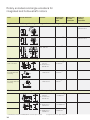
Rotary encoders for mounting on motors
Protection: up to IP 64 (EN 60 529)
Series
Overall dimensions
Mechanically
permissible
speed
Natural freq.
of stator
connection
Maximum
operating
temperature
Voltage supply
Rotary encoders with integral bearing and torque supports for Siemens drives
–1
i6 000 min
EQN/ERN 400
100 °C
3.6 V ± 14 V DC
10 V to 30 V DC
5 V DC ± 0.5 V
10 V to 30 V DC
i6 000 min–1
ERN 401
100 °C
5 V DC ± 0.5 V
10 V to 30 V DC
Rotary encoders with integral bearing for separate shaft coupling
ROC/ROQ/ROD 400
RIC/RIQ
–1
i12 000 min
Synchro flange
–
100 °C
–1
i16 000 min
3.6 V to 14 V DC
5 V DC ± 0.5 V
Clamping flange
10 V to 30 V DC
70 °C
i12 000 min–1
ROC/ROQ/ROD 1000
–
100 °C
5 V DC ± 0.5 V
100 °C
3.6 V to 14 V DC
5 V DC ± 0.5 V
70 °C
10 V to 30 V DC
5 V DC ± 0.25 V
i4 000 min–1
199
15
ROD 1900
150
1)
2)
Functional Safety upon request
After integral 5/10-fold interpolation
12
18
160
–
70 °C
10 V to 30 V DC
Signal periods
per revolution
Positions
per revolution
Distinguishable
revolutions
Interface
Model
More
information
2 048
8 192 (13 bits)
4 096
EnDat 2.1 / 01 with 1 VPP
EQN 425
Page 56
SSI
1 024
–
1 024
–/4 096
TTL
ERN 420
HTL
ERN 430
TTL
ERN 421
HTL
ERN 431
EnDat 2.2 / 01 with 1 VPP
ROC 413/ROQ 425
512, 2 048
8 192 (13 bits)
–
33 554 432 (25 bits)
EnDat 2.2/22
ROC 425/ROQ 4371)
50 to 10 000
–
TTL
ROD 426/ROD 420
50 to 5 000
HTL
ROD 436/ROD 430
50 to 10 000
TTL
ROD 466
1 000 to 5 000
1 VPP
ROD 486/ROD 480
EnDat 2.2 / 01 with 1 VPP
ROC 1013/ROQ 1025
512
8192 (13 bits)
–
8 388 608 (23 bits)
EnDat 2.2/22
ROC 1023/ROQ 1035
100 to 3 600
–
TTL
ROD 1020
1 VPP
ROD 1080
HTLs
ROD 1030
TTL
ROD 1070
HTL/HTLs
ROD 1930
5 000 to 36 0002)
600 to 2 400
–
–/4 096
Page 58
Catalog:
Rotary
Encoders
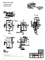
13
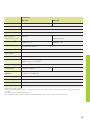
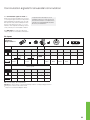
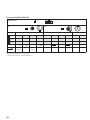
Rotary encoders and angle encoders for
integrated and hollow-shaft motors
Series
Overall dimensions
Diameter
Mechanically
permissible
speed
Natural freq.
of stator
connection
Maximum
operating
temperature
Angle encoders with integral bearing and integrated stator coupling
RCN 2000
–
i 1 500 min
–1
j 1 000 Hz
RCN 23xx: 60 °C
RCN 25xx: 50 °C
RCN 5000
–
i 1 500 min–1
j 1 000 Hz
RCN 53xx: 60 °C
RCN 55xx: 50 °C
RCN 8000
D:
60 mm
and 100 mm
i500 min
j 900 Hz
50 °C
ERA 4000
Steel scale drum
D1: 40 mm to
512 mm
D2: 76.75 mm to
560.46 mm
–1
i 10 000 min to
–1
i 1 500 min
–
80 °C
ERA 7000
For inside diameter
mounting
D: 458.62 mm to
1 146.10 mm
i 250 min–1 to
–1
i 220 min
–
80 °C
ERA 8000
For outside diameter
mounting
D: 458.11 mm to
1 145.73 mm
i50 min to
i 45 min–1
–
80 °C
–1
Angle encoders without integral bearing
–1
Modular encoders without integral bearing with magnetic graduation
–1
ERM 200
D1: 40 mm to
410 mm
D2: 75.44 mm to
452.64 mm
i19 000 min
to i3 000 min–1
–
100 °C
ERM 2400
D1: 40 mm to 100 mm
D2: 64.37 mm to
128.75 mm
i 42 000 min–1
–
to i 20 000 min–1
100 °C
ERM 2900
D1: 40 mm to 100 mm
D2: 58.06 mm to
120.96 mm
i 35 000 min /
i 16 000 min–1
1)
14
Interfaces for Fanuc and Mitsubishi controls upon request
2)
–1
Segment solutions upon request
1)
Voltage supply
System
accuracy
Signal periods
per revolution
Positions
per revolution
Interface
Model
More
information
3.6 V to 14 V DC
± 5“
± 2,5“
16 384
67 108 864 (26 bits)
268 435 456 (28 bits)
EnDat 2.2 / 02
with 1 VPP
RCN 2380
RCN 2580
± 5“
± 2,5“
–
67 108 864 (26 bits)
268 435 456 (28 bits)
EnDat 2.2/22
RCN 23103)
RCN 25103)
Catalog:
Angle
Encoders
with Integral
Bearing
± 5“
± 2,5“
16 384
67 108 864 (26 bits)
268 435 456 (28 bits)
EnDat 2.2 / 02
with 1 VPP
RCN 5380
RCN 5580
± 5“
± 2,5“
–
67 108 864 (26 bits)
268 435 456 (28 bits)
EnDat 2.2/22
RCN 53103)
RCN 55103)
± 2“
± 1“
32 768
536 870 912 (29 bits)
EnDat 2.2 / 02
with 1 VPP
RCN 8380
RCN 8580
± 2“
± 1“
–
EnDat 2.2/22
RCN 83103)
RCN 85103)
–
12 000 to 52 000
–
1 VPP
3.6 V to 14 V DC
3.6 V to 14 V DC
5 V DC ± 0.25 V
–
Full circle2)
36 000 to
90 000
–
1 VPP
ERA 4280 C Catalog:
Angle
ERA 4480 C Encoders
without
ERA 4880 C Integral
Bearing
ERA 7480 C
5 V DC ± 0.25 V
–
Full circle
36 000 to
90 000
2)
–
1 VPP
ERA 8480 C
5 V DC ± 0.5 V
–
600 to 3 600
–
TTL
ERM 220
1 VPP
ERM 280
1 VPP
ERM 2484
5 V DC ± 0.5 V
6 000 to 44 000
3 000 to 13 000
5 V DC ± 0.5 V
3)
–
512 to 1 024
–
256/400
–
Catalog:
Magnetic
Modular
Encoders
ERM 2984
Functional safety upon request
15
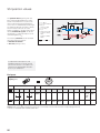
Exposed linear encoders for linear drives
Series
Overall dimensions
Traversing speed
Acceleration
in measuring
direction
LIP 400
i30 m/min
i 200 m/s
LIF 400
i72 m/min
i 200 m/s
LIC 4000
Absolute linear
encoder
i480 m/min
i 500 m/s
Accuracy grade
2
To ± 0.5 μm
2
± 3 μm
2
± 5 μm
1)
± 5 μm
LIDA 400
i480 m/min
2
i 200 m/s
± 5 μm
1)
± 5 μm
2
± 30 μm
2
± 2 μm
LIDA 200
i600 m/min
i 200 m/s
PP 200
Two-coordinate
encoder
i72 m/min
i 200 m/s
1)
After linear error compensation
16
Measuring lengths
Voltage supply
Signal
period
Cutoff frequency Switching
–3 dB
output
Interface
Model
More
information
70 mm to 420 mm
5 V DC ± 0.25 V
2 μm
j 250 kHz
–
1 VPP
LIP 481
Catalog:
Exposed
Linear
Encoders
70 mm to 1 020 mm
5 V DC ± 0.25 V
4 μm
j 300 kHz
Homing track 1 VPP
Limit switches
LIF 481
140 mm to
27 040 mm
3.6 V to 14 V DC
–
–
–
EnDat 2.2 / 22 LIC 4015
Resolution
0.001 μm
LIC 4017
140 to 6 040 mm
140 mm to
30 040 mm
5 V DC ± 0.25 V
20 μm
j 400 kHz
Limit switches 1 VPP
LIDA 485
LIDA 487
240 mm to 6 040 mm
Up to 10 000 mm
5 V DC ± 0.25 V
200 μm
j 50 kHz
–
1 VPP
LIDA 287
Measuring range
68 mm x 68 mm
5 V DC ± 0.25 V
4 μm
j 300 kHz
–
1 VPP
PP 281
17
Sealed linear encoders for linear drives
Protection: IP 53 to IP 641) (EN 60 529)
Series
Overall dimensions
Traversing
speed
Acceleration
in measuring
direction
Natural
frequency of
coupling
Measuring
lengths
LF
i60 m/min
i 100 m/s
2
j 2 000 Hz
50 mm to
1220 mm
LC
Absolute linear
encoder
i180 m/min
i 100 m/s
2
j 2 000 Hz
70 mm to
2 040 mm3)
LF
i60 m/min
i 100 m/s
2
j 2000 Hz
140 mm to
3040 mm
LC
Absolute linear
encoder
i180 m/min
i 100 m/s
2
j 2 000Hz
140 mm to
4240 mm
Linear encoders with slimline scale housing
Linear encoders with full-size scale housing
140 mm to
3040 mm
LB
1)
2)
3)
4)
i 100 m/s
j 780 Hz
3 240 mm to
28 040 mm
i120 m/min
(180 m/min
upon request)
i 60 m/s2
j 650 Hz
440 mm to
30 040 mm
(to 72 040 mm
upon request)
After installation according to mounting instructions
Interfaces for Siemens, Fanuc and Mitsubishi controls upon request
As of 1340 mm measuring length only with mounting spar or tensioning elements
Functional Safety upon request
18
2
i120 m/min
(180 m/min
upon request)
Accuracy
grade
Voltage supply
Signal period
Cutoff frequency Resolution
–3 dB
Interface2)
Type
More
information
± 5 μm
5 V DC ± 0.25 V
4 μm
j 250 kHz
–
1 VPP
LF 485
± 5 μm
3.6 V to 14 V DC
–
–
To 0.01 μm
EnDat 2.2/22
LC 4154)
Catalog:
Linear
Encoders for
Numerically
Controlled
Machine
Tools
± 3 μm
To 0.001 μm
± 2 μm;
± 3 μm
5 V DC ± 0.25 V
4 μm
j 250 kHz
–
1 VPP
LF 185
± 5 μm
3.6 V to 14 V DC
–
–
To 0.01 μm
EnDat 2.2/22
LC 1154)
EnDat 2.2/22
LC 211
± 3 μm
± 5 μm
To ± 5 μm
Catalog:
Linear
Encoders for
Numerically
Controlled
Machine
Tools
To 0.001 μm
3.6 V to 14 V DC
5 V DC ± 0.25 V
–
–
40 μm
j 250 kHz
40 μm
j 250 kHz
To 0.01 μm
EnDat 2.2 / 02 LC 281
with 1
VPP
–
1 VPP
LB 382
19
Rotary encoders and angle encoders
for three-phase AC and DC motors
General information
Speed stability
To ensure smooth drive performance, an
encoder must provide a large number of
measuring steps per revolution. The
encoders in the HEIDENHAIN product
program are therefore designed to supply
the necessary numbers of signal periods
per revolution to meet the speed stability
requirement.
Transmission of measuring signals
To ensure the best possible dynamic
performance with digitally controlled
motors, the sampling time of the speed
controller should not exceed approx.
256 μs. The feedback values for the
position and speed controller must
therefore be available in the controlling
system with the least possible delay.
HEIDENHAIN rotary and angular encoders
featuring integral bearing and stator
couplings provide very good performance:
shaft misalignment within certain
tolerances (see Specifications) do not
cause any position error or impair speed
stability.
High clock frequencies are needed to fulfill
such demanding time requirements on
position values transfer from the encoder
to the controlling system with a serial data
transmission (see also Interfaces; Absolute
Position Values). HEIDENHAIN encoders
for electric drives therefore provide the
position values via the fast, purely serial
EnDat 2.2 interface, or transmit additional
incremental signals, which are available
without delay for use in the subsequent
electronics for speed and position control.
At low speeds, the position error of the
encoder within one signal period affects
speed stability. In encoders with purely
serial data transmission, the LSB (Least
Significant Bit) goes into the speed
stability. (See also Measuring Accuracy.)
For standard drives, manufacturers primarily use the especially robust HEIDENHAIN absolute encoders without integral
bearing ECI/EQI or rotary encoders with
TTL or HTL compatible output signals—
as well as additional commutation signals
for permanent-magnet DC drives.
For digital speed control on machines
with high requirements for dynamics, a
large number of measuring steps is
required—usually above 500 000 per
revolution. For applications with standard
drives, as with resolvers, approx. 60 000
measuring steps per revolution are
sufficient.
HEIDENHAIN encoders for drives with
digital position and speed control are
therefore equipped with the purely serial
EnDat22 interface, or they additionally
provide sinusoidal incremental signal
with signal periods of 1 VPP (EnDat01).
The high internal resolution of the EnDat22
encoders permit resolutions greater than
19 bits (524 288 measuring steps) in
inductive systems and greater than 23 bits
(approx. 8 million measuring steps) in
photoelectric encoders.
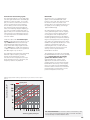
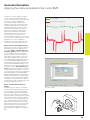
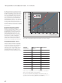
Thanks to their high signal quality, the
sinusoidal incremental signals of the
EnDat01 encoders can be highly
subdivided in the subsequent electronics
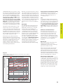
(diagram 1). Even at shaft speeds of
12 000 min–1, the signal arrives at the input
circuit of the controlling system with a
frequency of only approx. 400 kHz
(Diagram 2). 1 VPP incremental signals
permit cable lengths up to 150 meters.
(See also Incremental Signals – 1 VPP)
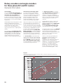
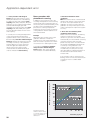
Diagram 1:
Signal periods per revolution and the resulting number of measuring steps per revolution as a
function of the subdivision factor
Measuring steps per revolution f
Subdivision factor
Signal periods per revolution f
20
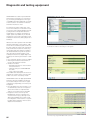
Important encoder specifications can be
read from the memory of the EnDat encoder for automatic self-configuration, and
motor-specific parameters can be saved in
the OEM memory area of the encoder. The
usable size of the OEM memory on the rotary encoders in the current catalogs is at
least 1.4 KB (f 704 EnDat words).
Most absolute encoders themselves
already subdivide the sinusoidal scanning
signals by a factor of 4 096 or greater. If the
transmission of absolute positions is fast
enough (for example, EnDat 2.1 with
2 MHz or EnDat 2.2 with 8 MHz clock
frequency), these systems can do without
incremental signal evaluation.
Benefits of this data transmission technology include greater noise immunity of the
transmission path and less expensive connectors and cables. Rotary encoders with
EnDat 2.2 interface offer the additional feature of being able to evaluate an external
temperature sensor, located in the motor
coil, for example. The digitized temperature
values are transmitted as part of the
EnDat 2.2 protocol without an additional
line.
Bandwidth
The attainable gain for the position and
speed control loops, and therefore the
bandwidth of the drives for command
response and control reliability, are
sometimes limited by the rigidity of the
coupling between the motor shaft and
encoder shaft as well as by the natural
frequency of the coupling. HEIDENHAIN
therefore offers rotary and angular
encoders for high-rigidity shaft coupling.
The stator couplings mounted on the
encoders have a high natural frequency
up to 1800 Hz. For the modular and
inductive rotary encoders, the stator and
rotor are firmly screwed to the motor
housing and to the shaft (see also
Mechanical design types and mounting).
Diagram 2:
Shaft speed and resulting output frequency as a function of the number of
signal periods per revolution
Output frequency [kHz] f
Signal periods per revolution
Fault exclusion for mechanical coupling
HEIDENHAIN encoders designed for
functional safety can be mounted so that
the rotor or stator fastening does not
accidentally loosen.
Size
A higher permissible operating temperature permits a smaller motor size for a specific rated torque. Since the temperature of
the motor also affects the temperature of
the encoder, HEIDENHAIN offers encoders
for permissible operating temperatures
up to 120 °C. These encoders make it possible to design machines with smaller motors.
Power loss and noise emission
The power loss of the motor, the
accompanying heat generation, and the
acoustic noise of motor operation are
influenced by the position error of the
encoder within one signal period. For this
reason, encoders with a high signal quality
of better than ± 1 % of the signal period
are preferred. (See also Measuring
Accuracy.)
Bit error rate
With rotary encoders with purely serial
interface for integration in motors,
HEIDENHAIN recommends conducting a
type test for the bit error rate.
When using functionally safe encoders
without closed metal housings and/or
cable assemblies that do not comply with
the electrical connection directives (see
General electrical information) it is always
necessary to measure the bit error rate in a
type test under application conditions.
Data transfer in hybrid cables
For particularly limited spaces in machines
or drag chains, motors that contain encoders with the EnDat22 interface can be connected to the subsequent electronics
through hybrid cable technology. The HMC
6 hybrid cables save a good deal of space
because they contain all the lines for the
encoder, the motor, and the brake. Cable
lengths up to 100 m are permissible.
Shaft speed [min–1] f
21
Properties and mounting
HEIDENHAIN absolute encoders for “digital” drives also supply additional sinusoidal
incremental signals with the same characteristics as those described above. Absolute encoders from HEIDENHAIN use the
EnDat interface (for Encoder Data) for the
serial data transmission of absolute position values and other information for automatic self-configuration, monitoring and
diagnosis. (See Absolute Position Values –
EnDat.) This makes it possible to use the
same subsequent electronics and cabling
technology for all HEIDENHAIN encoders.
Linear encoders for linear drives
General information
Selection criteria for linear encoders
HEIDENHAIN recommends the use of
exposed linear encoders whenever the
severity of contamination inherent in a
particular machine environment does not
preclude the use of optical measuring
systems, and if relatively high accuracy is
desired, e.g. for high-precision machine
tools and measuring equipment, or for
production, testing and inspecting
equipment in the semiconductor industry.
Particularly for applications on machine
tools that release coolants and lubricants,
HEIDENHAIN recommends sealed linear
encoders. Here the requirements on the
mounting surface and on machine guideway accuracy are less stringent than for exposed linear encoders, and therefore installation is faster.
Speed stability
To ensure smooth-running servo
performance, the linear encoder must
permit a resolution commensurate with
the given speed control range:
• On handling equipment, resolutions in
the range of several microns are
sufficient.
• Feed drives for machine tools need
resolutions of 0.1 μm and finer.
• Production equipment in the
semiconductor industry requires
resolutions of a few nanometers.
Traversing speeds
Exposed linear encoders function without
contact between the scanning head and
the scale. The maximum permissible
traversing speed is limited only by the
cutoff frequency (–3 dB) of the output
signals.
On sealed linear encoders, the scanning
unit is guided along the scale on a ball
bearing. Sealing lips protect the scale and
scanning unit from contamination. The ball
bearing and sealing lips permit mechanical
traversing speeds up to 180 m/min.
At low traversing speeds, the position
error within one signal period has a
decisive influence on the speed stability of
linear motors. (See also Measuring
Accuracy.)
Signal period and resulting measuring step as a function of the subdivision
factor
Measuring step [μm] f
Subdivision factor
Signal period [μm] f
22
Transmission of measuring signals
The information above on rotary and angle
encoder signal transmission essentially applies also to linear encoders. If, for example, one wishes to traverse at a minimum
velocity of 0.01 m/min with a sampling
time of 250 μs, and if one assumes that
the measuring step should change by at
least one measuring step per sampling cycle, then one needs a measuring step of
approx. 0.04 μm. To avoid the need for special measures in the subsequent electronics, input frequencies should be limited to
less than 1 MHz.
Linear encoders with sinusoidal output
signals or absolute position values according to EnDat 2.2 are best suited for high
traversing speeds and small measuring
steps. Sinusoidal voltage signals with levels of 1 VPP attain a –3 dB cutoff frequency
of approx. 200 kHz and more at a permissible cable length of up to 150 m.
The figure below illustrates the relationship
between output frequency, traversing
speeds, and signal periods of linear
encoders. Even at a signal period of 4 μm
and a traversing velocity of 70 m/min, the
frequency reaches only 300 kHz.
Bandwidth
On linear motors, a coupling lacking in
rigidity can limit the bandwidth of the
position control loop. The manner in which
the linear encoder is mounted on the
machine has a very significant influence on
the rigidity of the coupling. (See Design
Types and Mounting.)
On sealed linear encoders, the scanning
unit is guided along the scale. A coupling
connects the scanning carriage with the
mounting block and compensates the
misalignment between the scale and the
machine guideways. This permits relatively
large mounting tolerances. The coupling is
very rigid in the measuring direction and is
flexible in the perpendicular direction. If the
coupling is insufficiently rigid in the
measuring direction, it could cause low
natural frequencies in the position and
velocity control loops and limit the
bandwidth of the drive.
The sealed linear encoders recommended
by HEIDENHAIN for linear motors generally
have a natural frequency of coupling
greater than 650 Hz or 2 kHz in the
measuring direction, which in most
applications exceeds the mechanical
natural frequency of the machine and the
bandwidth of the velocity control loop by
factors of at least 5 to 10. HEIDENHAIN
linear encoders for linear motors therefore
have practically no limiting effect on the
position and speed control loops.
Traversing speed and resulting output frequency as a function of the signal
period
Output frequency [kHz] f
Signal period
Traversing speed [m/min] f
For more information on linear encoders for linear drives, refer
to our catalogs Exposed Linear Encoders and Linear Encoders
for Numerically Controlled Machine Tools.
23
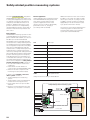
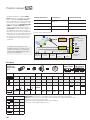
Safety-related position measuring systems
The term Functional Safety designates
HEIDENHAIN encoders that can be used
in safety-related applications. These encoders operate as single-encoder systems
with purely serial data transmission via
EnDat 2.2. Reliable transmission of the
position is based on two independently
generated absolute position values and on
error bits. These are then provided to the
safe control.
Basic principle
HEIDENHAIN measuring systems for safety-related applications are tested for compliance with EN ISO 13 849-1 (successor to
EN 954-1) as well as EN 61 508 and
EN 61 800-5-2. These standards describe
the assessment of safety-related systems,
for example based on the failure probabilities of integrated components and subsystems. This modular approach helps the
manufacturers of safety-related systems to
implement their complete systems, because they can begin with subsystems that
have already been qualified. Safety-related
position measuring systems with purely
serial data transmission via EnDat 2.2 accommodate this technique. In a safe drive,
the safety-related position measuring system is such a subsystem. A safety-related
position measuring system consists of:
• Encoder with EnDat 2.2 transmission
component
• Data transfer line with EnDat 2.2
communication and HEIDENHAIN cable
• EnDat 2.2 receiver component with
monitoring function (EnDat master)
In practice, the complete “safe servo
drive” system consists of:
• Safety-related position measuring
system
• Safety-related control (including EnDat
master with monitoring functions)
• Power stage with motor power cable
and drive
• Physical connection between encoder
and drive (e.g. rotor/stator connection)
Field of application
Safety-related position measuring systems
from HEIDENHAIN are designed so that
they can be used as single-encoder
systems in applications with control
category SIL 2 (according to EN 61 508),
performance level “d”, category 3
(according to EN ISO 13 849).
Additional measures in the control make it
possible to use certain encoders for applications up to SIL-3, PL “e”, category 4. The
suitability of these encoders is indicated
appropriately in the documentation (catalogs / product information sheets).
The functions of the safety-related position
measuring system can be used for the
following safety tasks in the complete
system (also see EN 61 800-5-2):
SS1
Safe Stop 1
SS2
Safe Stop 2
SOS
Safe Operating Stop
SLA
Safely Limited Acceleration
SAR
Safe Acceleration Range
SLS
Safely Limited Speed
SSR
Safe Speed Range
SLP
Safely Limited Position
SLI
Safely Limited Increment
SDI
Safe Direction
SSM
Safe Speed Monitor
Safety functions according to EN 61 800-5-2
Safety-related position measuring system
EnDat master
Safe control
Drive motor
Encoder
Power stage
Power cable
Complete safe drive system
24
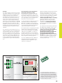
Function
The safety strategy of the position measuring system is based on two mutually independent position values and additional error bits produced in the encoder and
transmitted over the EnDat 2.2 protocol to
the EnDat master. The EnDat master assumes various monitoring functions with
which errors in the encoder and during
transmission can be revealed. For example,
the two position values are then compared.
The EnDat master then makes the data
available to the safe control. The control periodically tests the safety-related position
measuring system to monitor its correct
operation.
The architecture of the EnDat 2.2 protocol
makes it possible to process all safety-relevant information and control mechanisms
during unconstrained controller operation.
This is possible because the safety-relevant
information is saved in the additional information. According to EN 61 508, the architecture of the position measuring system
is regarded as a single-channel tested system.
Measured-value
acquisition
Documentation on the integration of
the position measuring system
The intended use of position measuring
systems places demands on the control,
the machine designer, the installation technician, service, etc. The necessary information is provided in the documentation for
the position measuring systems.
In order to be able to implement a position
measuring system in a safety-related
application, a suitable control is required.
The control assumes the fundamental task
of communicating with the encoder and
safely evaluating the encoder data.
The requirements for integrating the EnDat
master with monitoring functions in the
safe control are described in the HEIDENHAIN document 533095. It contains, for
example, specifications on the evaluation
and processing of position values and error
bits, and on electrical connection and cyclic
tests of position measuring systems.
Document 1000344 describes additional
measures that make it possible to use
suitable encoders for applications up to
SIL-3, PL “e”, category 4.
Data transmission line
Machine and plant manufacturers need not
attend to these details. These functions
must be provided by the control. Product
information sheets, catalogs and mounting
instructions provide information to aid the
selection of a suitable encoder. The
product information sheets and catalogs
contain general data on function and
application of the encoders as well as
specifications and permissible ambient
conditions. The mounting instructions
provide detailed information on installing
the encoders.
The architecture of the safety system and
the diagnostic possibilities of the control
may call for further requirements. For
example, the operating instructions of
the control must explicitly state
whether fault exclusion is required for
the loosening of the mechanical
connection between the encoder and
the drive.The machine designer is obliged
to inform the installation technician and
service technicians, for example, of the
resulting requirements.
Reception of measured values
Safe control
Position 2
EnDat interface
Interface 1
Position 1
EnDat
master
(protocol and cable)
Interface 2
Catalog of measures
Two independent
position values
Serial data transfer
Position values and error bits via
two processor interfaces
Internal monitoring
Monitoring functions
Protocol formation
Efficiency test
For more information on the topic of
functional safety, refer to the technical
information documents Safety-Related
Position Measuring Systems and SafetyRelated Control Technology as well as the
product information document of the
functional safety encoders.
Safety-related position measuring system
25
Measuring principles
Measuring standard
HEIDENHAIN encoders with optical scanning incorporate measuring standards of
periodic structures known as graduations.
These graduations are applied to a carrier
substrate of glass or steel. The scale
substrate for large diameters is a steel
tape.
HEIDENHAIN manufactures the precision
graduations in specially developed, photolithographic processes.
• AURODUR: matte-etched lines on goldplated steel tape with typical graduation
period of 40 μm
• METALLUR: contamination-tolerant
graduation of metal lines on gold, with
typical graduation period of 20 μm
• DIADUR: extremely robust chromium
lines on glass (typical graduation period
of 20 μm) or three-dimensional
chromium structures (typical graduation
period of 8 μm) on glass
• SUPRADUR phase grating: optically
three dimensional, planar structure;
particularly tolerant to contamination;
typical graduation period of 8 μm and
finer
• OPTODUR phase grating: optically three
dimensional, planar structure with
particularly high reflectance, typical
graduation period of 2 μm and finer
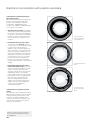
With the absolute measuring method,
the position value is available from the encoder immediately upon switch-on and can
be called at any time by the subsequent
electronics. There is no need to move the
axes to find the reference position. The absolute position information is read from the
grating on the circular scale, which is designed as a serial code structure or consists of several parallel graduation tracks.
A separate incremental track or the track
with the finest grating period is interpolated for the position value and at the same
time is used to generate an optional incremental signal.
In singleturn encoders, the absolute
position information repeats itself with
every revolution. Multiturn encoders can
also distinguish between revolutions.
Circular graduations of absolute rotary encoders
Magnetic encoders use a graduation carrier
of magnetizable steel alloy. A graduation
consisting of north poles and south poles is
formed with a grating period of 400 μm.
Due to the short distance of effect of
electromagnetic interaction, and the very
narrow scanning gaps required, finer
magnetic graduations are not practical.
Encoders using the inductive scanning
principle work with graduation structures of
copper and nickel. The graduation is applied
to a carrier material for printed circuits.
With the incremental measuring
method, the graduation consists of a
periodic grating structure. The position
information is obtained by counting the
individual increments (measuring steps)
from some point of origin. Since an
absolute reference is required to ascertain
positions, the graduated disks are provided
with an additional track that bears a
reference mark.
Circular graduations of incremental rotary encoders
26
The absolute position established by the
reference mark is gated with exactly one
measuring step.
The reference mark must therefore be
scanned to establish an absolute reference
or to find the last selected datum.
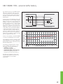
Scanning methods
Photoelectric scanning
Most HEIDENHAIN encoders operate
using the principle of photoelectric
scanning. Photoelectric scanning of a
measuring standard is contact-free, and as
such, free of wear. This method detects
even very fine lines, no more than a few
microns wide, and generates output
signals with very small signal periods.
The ECN and EQN absolute rotary encoders with optimized scanning have a single
large photosensor instead of a group of individual photoelements. Its structures have
the same width as that of the measuring
standard. This makes it possible to do without the scanning reticle with matching
structure.
The ERN, ECN, EQN, ERO and ROD, RCN,
RQN rotary encoders use the imaging
scanning principle.
Put simply, the imaging scanning principle
functions by means of projected-light
signal generation: two graduations with
equal or similar grating periods are moved
relative to each other—the scale and the
scanning reticle. The carrier material of the
scanning reticle is transparent, whereas
the graduation on the measuring standard
may be applied to a transparent or
reflective surface.
When parallel light passes through a grating, light and dark surfaces are projected at
a certain distance. An index grating with
the same or similar grating period is located here. When the two gratings move in
relation to each other, the incident light is
modulated: if the gaps are aligned, light
passes through. If the lines of one grating
coincide with the gaps of the other, no light
passes through. A structured photosensor
or photovoltaic cells convert these variations in light intensity into nearly sinusoidal
electrical signals. Practical mounting tolerances for encoders with the imaging scanning principle are achieved with grating periods of 10 μm and larger.
LED light
source
Condenser lens
Graduated
disk
Incremental track
Absolute track
Structured photosensor
with scanning reticle
Photoelectric scanning according to the imaging scanning principle
Other scanning principles
Some encoders function according to other
scanning methods. ERM encoders use a
permanently magnetized MAGNODUR
graduation that is scanned with magnetoresistive sensors.
ECI/EQI/EBI and RIC/RIQ rotary encoders
operate according to the inductive measuring principle. Here, moving graduation
structures modulate a high-frequency signal in its amplitude and phase. The position
value is always formed by sampling the
signals of all receiver coils distributed evenly around the circumference. This permits
large mounting tolerances with high resolution.
27
Electronic commutation with position encoders
Commutation in permanent-magnet
three-phase motors
Before start-up, permanent-magnet threephase motors must have an absolute
position value available for electrical
commutation. HEIDENHAIN rotary
encoders are available with different types
of rotor position recognition:
• Absolute rotary encoders in singleturn
and multiturn versions provide the absolute position information immediately after switch-on. This makes it immediately
possible to derive the exact position of
the rotor and use it for electronic commutation.
Circular scale with
serial code track and
incremental track
• Incremental rotary encoders with a
second track—the Z1 track—provide
one sine and one cosine signal (C and D)
for each motor shaft revolution in
addition to the incremental signals. For
sine commutation, rotary encoders with
a Z1 track need only a subdivision unit
and a signal multiplexer to provide both
the absolute rotor position from the Z1
track with an accuracy of ± 5° and the
position information for speed and
position control from the incremental
track (see also Interfaces—Commutation
signals).
• Incremental rotary encoders with
block commutation tracks also output
three commutation signals U, V and W.
which are used to drive the power
electronics directly. These encoders are
available with various commutation
tracks. Typical versions provide 3 signal
periods (120° mech.) or 4 signal periods
(90° mech.) per commutation and
revolution. Independently of these
signals, the incremental square-wave
signals serve for position and speed
control. (See also Interfaces—
Commutation signals.)
Commutation of synchronous linear
motors
Like absolute rotary and angular encoders,
absolute linear encoders of the LIC and LC
series provide the exact position of the
moving motor part immediately after
switch-on. This makes it possible to start
with maximum holding load on vertical
axes even at a standstill.
Keep in mind the switch-on behavior of
the encoders (see Interfaces catalog,
ID 1078628-xx).
28
Circular scale with Z1
track
Circular scale with
block commutation
tracks
Measuring accuracy
The quantities influencing the accuracy of
linear encoders are listed in the Linear
Encoders for Numerically Controlled
Machine Tools and Exposed Linear
Encoders catalogs.
The accuracy of angular measurement is
mainly determined by
• the quality of the graduation,
• the quality of the scanning process,
• the quality of the signal processing
electronics,
• the eccentricity of the graduation to the
bearing,
• the error of the bearing,
• the coupling to the measured shaft, and
• the elasticity of the stator coupling (ERN,
ECN, EQN) or shaft coupling (ROD, ROC,
ROQ, RIC, RIQ)
These factors of influence are comprised
of encoder-specific error and applicationdependent issues. All individual factors of
influence must be considered in order to
assess the attainable total accuracy.
Error specific to the measuring
device
For rotary encoders, the error that is
specific to the measuring device is shown
in the Specifications as the system
accuracy.
The extreme values of the total deviations
of a position are—referenced to their mean
value—within the system accuracy ± a.
The system accuracy reflects position
errors within one revolution as well as
those within one signal period and—for
rotary encoders with stator coupling—the
errors of the shaft coupling.
Position error within one signal period
Position errors within one signal period are
considered separately, since they already
have an effect even in very small angular
motions and in repeated measurements.
They especially lead to speed ripples in the
speed control loop.
The position error within one signal period
± u results from the quality of the scanning
and—for encoders with integrated pulseshaping or counter electronics—the quality
of the signal-processing electronics. For encoders with sinusoidal output signals, however, the errors of the signal processing
electronics are determined by the subsequent electronics.
These errors are considered when
specifying the position error within one
signal period. For rotary encoders with
integral bearing and sinusoidal output
signals it is better than ± 1% of the signal
period or better than ± 3% for encoders
with square-wave output signals. These
signals are suitable for up to 100-fold PLL
subdivision.
The position error within one signal period
± u is indicated in the specifications of the
angle encoders.
As the result of increased reproducibility of
a position, much smaller measuring steps
are still useful.
Position error within one signal period
Position f
Signal level f
Position error within
one signal period
Position error f
Position errors within one revolution
Position error f
The following individual factors influence
the result:
• The size of the signal period
• The homogeneity and period definition
of the graduation
• The quality of scanning filter structures
• The characteristics of the sensors
• The stability and dynamics of further
processing of the analog signals
Signal period
360° elec.
29
Application-dependent error
For rotary encoders with integral
bearing, the specified system accuracy
already includes the error of the bearing.
For angle encoders with separate shaft
coupling (ROD, ROC, ROQ, RIC, RIQ), the
angle error of the coupling must be added
(see Mechanical design types and
mounting). For angle encoders with stator
coupling (ERN, ECN, EQN), the system
accuracy already includes the error of the
shaft coupling.
Rotary encoders with
photoelectric scanning
In contrast, the mounting and adjustment
of the scanning head normally have a
significant effect on the accuracy that can
be achieved by encoders without integral
bearings. Of particular importance are the
mounting eccentricity of the graduation
and the radial runout of the measured
shaft. The application-dependent error
values for these encoders must be
measured and calculated individually in
order to evaluate the total accuracy.
Example
ERO 1420 rotary encoder with a mean
graduation diameter of 24.85 mm:
A radial runout of the measured shaft of
0.02 mm results in a position error within
one revolution of ± 330 angular seconds.
In addition to the system accuracy, the
mounting and adjustment of the scanning
head normally have a significant effect on
the accuracy that can be achieved by rotary
encoders without integral bearings with
photoelectric scanning. Of particular
importance are the mounting eccentricity
of the graduation and the radial runout of
the measured shaft.
To evaluate the accuracy of modular
rotary encoders without integral
bearing (ERO), each of the significant
errors must be considered individually.
1. Directional deviations of the
graduation
ERO: The extreme values of the directional
deviation with respect to their mean value
are shown in the Specifications as the
graduation accuracy for each model. The
graduation accuracy and the position error
within a signal period comprise the system
accuracy.
2. Errors due to eccentricity of the
graduation to the bearing
Under normal circumstances, the bearing
will have a certain amount of radial
deviation or geometric error after the disk/
hub assembly is mounted. When centering
using the centering collar of the hub,
please note that, for the encoders listed in
this catalog, HEIDENHAIN guarantees an
eccentricity of the graduation to the
centering collar of under 5 μm. For the
modular rotary encoders, this accuracy
value presupposes a diameter deviation of
zero between the drive shaft and the
"master shaft."
Measuring error M [angular seconds] f
If the centering collar is centered on the
bearing, then in a worst-case situation both
eccentricity vectors could be added
together.
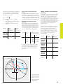
Resultant measured
deviations M for various
eccentricity values e as a
function of graduation
diameter D
30
Eccentricity e [μm] f
The following relationship exists between
the eccentricity e, the mean graduation
diameter D and the measuring error M
(see illustration below):
M = ± 412 · e
D
M = Measuring error in ” (angular
seconds)
e = Eccentricity of the radial grating to
the bearing in μm
D = Graduation centerline diameter
in mm
Model
Mean
graduation
diameter D
Error per
1 μm of
eccentricity
ERO 1420 D = 24.85 mm ± 16.5”
ERO 1470
ERO 1480
ERO 1225 D = 38.5 mm
ERO 1285
3. Error due to radial runout of the
bearing
The equation for the measuring error M is
also valid for radial deviation of the bearing
if the value e is replaced with the eccentricity value, i.e. half of the radial deviation (half
of the displayed value). Bearing compliance
to radial shaft loading causes similar errors.
4. Position error within one signal
period Mu
The scanning units of all HEIDENHAIN encoders are adjusted so that without any
further electrical adjustment being necessary while mounting, the maximum position error values within one signal period
will not exceed the values listed below.
Model Line
count
Position error within
one signal period Mu
2 048
1 500
1 024
1 000
512
All with all rotary encoders without integral
bearing, the attainable accuracy for those
with inductive scanning is dependent on
the mounting and application conditions.
The system accuracy is given for 20 °C and
low speed. The full use of all permissible
tolerances for operating temperature, shaft
speed, supply voltage, scanning gap and
mounting are to be calculated for the
typical total error.
Thanks to the circumferential scanning of
the inductive rotary encoders, the total
error is less than for rotary encoders
without integral bearing but with optical
scanning. Because the total error cannot
be calculated through a simple calculation
rule, the values are provided in the
following table.
TTL
1 VPP
Model
i ± 19.0”
i ± 26.0”
i ± 38.0”
i ± 40.0”
i ± 76.0”
i ± 6.5”
i ± 8.7”
i ± 13.0”
i ± 14.0”
i ± 25.0”
ECI 1100
± 280”
EQI 1100
EnDat01/21
± 480”
ECI 1100
EBI 1100
EnDat22
± 120”
± 280”
ECI 1300
EQI 1300
EnDat22
± 65”
± 120”
ECI 1300
EQI 1300
EnDat01
± 180”
± 280”
ECI 100
EBI 100
± 90”
± 180”
± 10.7”
ERO
Rotary encoders with inductive
scanning
The values for the position errors within
one signal period are already included in
the system accuracy. Larger errors can
occur if the mounting tolerances are
exceeded.
System
accuracy
Total
deviation
Scanning unit
Measuring error M as a
function of the mean
graduation diameter D
and the eccentricity e
M Center of graduation
M "True" angle
M‘ Scanned angle
31
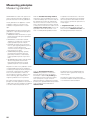
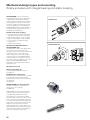
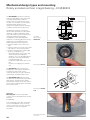
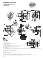
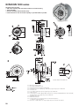
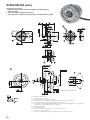
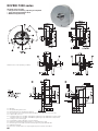
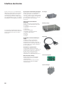
Mechanical design types and mounting
Rotary encoders with integral bearing and stator coupling
ECN/EQN/ERN rotary encoders have
integrated bearings and a mounted stator
coupling. The encoder shaft is directly
connected with the shaft to be measured.
During angular acceleration of the shaft,
the stator coupling must absorb only that
torque caused by friction in the bearing.
ECN/EQN/ERN rotary encoders therefore
provide excellent dynamic performance
and a high natural frequency.
ECN/EQN 1100
Benefits of the stator coupling:
• No axial mounting tolerances between
shaft and stator housing for ExN 1300
• High natural frequency of the coupling
• High torsional rigidity of shaft coupling
• Low mounting or installation space
requirement
• Simple axial mounting
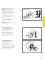
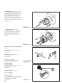
Mounting the ECN/EQN 1100 and
ECN/EQN/ERN 1300
The blind hollow shaft or the taper shaft of
the encoder is connected at its end
through a central screw with the measured
shaft. The encoder is centered on the
motor shaft by the hollow shaft or taper
shaft. The stator of the ECN/EQN 1100 is
connected without a centering collar to a
flat surface with two clamping screws. The
stator of the ECN/EQN/ERN 1300 is
screwed into a mating hole by an axially
tightened screw.
Mounting accessories
ECN 11xx: mounting aid
For disengaging the PCB connector,
see page 34
ECN/EQN 11xx: mounting aid
For turning the encoder shaft from the back
so that the positive-locking connection
between the encoder and measured shaft
can be found.
ID 821017-01
ERN/ECN/EQN 13xx: inspection tool
To inspect the shaft connection (fault
exclusion for rotor coupling)
ID 680644-01
HEIDENHAIN recommends checking the
holding torque of frictional connections
(e.g. taper shaft, blind hollow shaft).
The testing tool is screwed in the M10
back-off thread on the back of the encoder.
Due to the low screwing depth it does not
touch the shaft-fastening screw. When the
motor shaft is locked, the testing torque is
applied to the extension by a torque
wrench (hexagonal 6.3 mm width across
flats). After any nonrecurring settling, there
must not be any relative motion between
the motor shaft and encoder shaft.
32
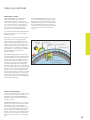
ECN/EQN/ERN 1300
Mounting the ECN/EQN/ERN 1000 and
ERN 1x23
The rotary encoder is slid by its hollow
shaft onto the measured shaft and
fastened by two screws or three eccentric
clamps. The stator is mounted without a
centering flange to a flat surface with four
cap screws or with 2 cap screws and
special washers.
ECN/EQN/ERN 1000
The ECN/EQN/ERN 1000 encoders feature
a blind hollow shaft, the ERN 1123 a hollow
through shaft.
Accessory ECN/EQN/ERN 1000
Washer
For increasing the natural frequency fN and
mounting with only two screws.
ID 334653-01 (2 pieces)
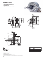
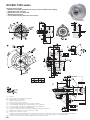
Mounting the EQN/ERN 400
The EQN/ERN 400 encoders are designed
for use on Siemens asynchronous motors.
They serve as replacement existing
Siemens rotary encoders.
The rotary encoder is slid by its hollow
shaft onto the measured shaft and
fastened by the clamping ring. On the
stator side, the encoder is fixed by its
torque support to a plane surface.
Mounting the EQN/ERN 401
The ERN 401 encoders are designed for
use on Siemens asynchronous motors.
They serve as replacement existing
Siemens rotary encoders.
The rotary encoder features a solid shaft
with a M8 external thread, centering taper
and SW8 width across flats. It centers
itself during fastening to the motor shaft.
The stator coupling is fastened by special
clips to the motor’s ventilation grille.
33
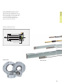
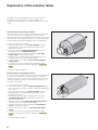
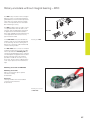
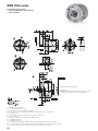
Mechanical design types and mounting
Rotary encoders without integral bearing – ECI/EBI/EQI
The ECI/EBI/EQI inductive encoders are
without integral bearing. This means that
mounting and operating conditions
influence the functional reserves of the
encoder. It is essential to ensure that the
specified mating dimensions and
tolerances are maintained in all operating
conditions (see Mounting Instructions).
The application analysis must result in
values within specification for all possible
operating conditions (particularly under
max. load and at minimum and maximum
operating temperature) and under
consideration of the signal amplitude
(inspection of scanning gap and mounting
tolerance at room temperature). This
applies particularly for the measured
• maximum radial runout of the motor
shaft
• maximum axial runout of the motor shaft
with respect to the mounting surface
• maximum and minimum scanning gap
(a) (also in combination) e.g.:
– The length relation of the motor shaft
and housing under temperature
influence (T1; T2; À1; À2) depending on
the position of the fixed bearing (b)
– of the bearing play (CX)
– nondynamic shaft offsets due to load
(X1)
– the effect of engaging motor brakes
(X2)
0.05 A
Cx
Scanning gap a = 0.65±0.3 mm
T2
$
X1, X2
0.05 A
Schematic
representation
ECI/EBI 100
Mounting the ECI 119
The ECI/EBI 100 rotary encoders are
prealigned on a flat surface and then the
locked hollow shaft is slid onto the
measured shaft. The encoder is fastened
and the shaft clamped by axial screws.
The ECI/EBI/EQI 1100 inductive rotary
encoders are mounted as far as possible in
axial direction. The blind hollow shaft is
attached with a central screw. The stator of
the encoder is clamped against a shoulder
by two axial screws.
Mounting the ECI/EQI
1100
Accessory
Mounting aid for removing the PCB
connector for ECI 1118 (EnDat 22), ECI 119,
ECN 11xx
ID 592818-01
To avoid damage to the cable, the pulling
force must be applied on the connector,
and not on the wires. For other encoders,
use tweezers or the mounting aid if
necessary.
Mounting aid for PCB
connector
34
T1
b
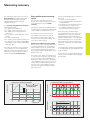
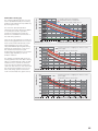
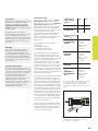
Once the encoder has been mounted, the
actual working gap between the rotor and
stator can be measured indirectly via the
signal amplitude in the rotary encoder,
using the PWM 20 adjusting and testing
package. The characteristic curves show
the correlation between the signal
amplitude and the deviation from the ideal
scanning gap, depending on various
ambient conditions.
The example of ECI/EQI 1100 shows the
resulting deviation from the ideal scanning
gap for a signal amplitude of 80 % at ideal
conditions. Due to tolerances within the
rotary encoder, the deviation is between
+0.07 mm and +0.15 mm. This means that
the maximum permissible motion of the
drive shaft during operation is between
–0.27 mm and +0.05 mm (green arrows).
Amplitude [%] f
ECI/EQI 1100 with EnDat 2.1
Amplitude [%] f
The maximum permitted deviation
indicated in the mating dimensions applies
to mounting as well as to operation.
Tolerances used during mounting are
therefore not available for axial motion of
the shaft during operation.
ECI/EBI 1100 with EnDat 2.2
Amplitude [%] f
Permissible scanning gap
The scanning gap between the rotor and
stator is predetermined by the mounting
situation. Later adjustment is possible only
by inserting shim rings.
ECI/EBI 100
Tolerance at the time of shipping
Temperature influence at max./min.
Influence of the supply voltage at ± 5 %
Deviation from the ideal working gap [mm] f
Tolerance at the time of shipping incl. influence of the
power supply
Temperature influence at max./min.
Deviation from the ideal working gap [mm] f
Tolerance at the time of shipping incl. influence of the
power supply
Temperature influence at max./min.
Deviation from the ideal working gap [mm] f
35
The ECI/EQI 1300 with EnDat01 inductive
rotary encoders are mechanically compatible with the ExN 1300 photoelectric encoders. The taper shaft (a bottomed hollow
shaft is available as an alternative) is fastened with a central screw. The stator of
the encoder is clamped by an axially tightened bolt in the location hole. The scanning
gap between rotor and stator must be set
during mounting.
Mounting the
ECI/EQI 1300 EnDat01
The ECI/EQI 1300 inductive rotary
encoders with EnDat22 are mounted as far
as possible in axial direction. The blind
hollow shaft is attached with a central
screw. The stator of the encoder is
clamped against a shoulder by three axial
screws.
Mounting the
ECI/EQI 1300 EnDat22
Mounting accessories for ECI/EQI 1300
EnDat01
Adjustment aid for setting the scale-toreticle gap
ID 335529-xx
Mounting aid for adjusting the rotor
position to the motor emf
ID 352481-02
Accessories for ECI/EQI
For inspecting the scanning gap and
adjusting the ECI/EQI 1300
Mounting and adjusting
aid for ECI/EQI 1300
EnDat01
Connecting cable
For EIB 741, PWM 20
Including 3 adapter connectors, 12-pin and
3 adapter connectors, 15-pin
ID 621742-01
Adapter connectors
Three connectors for replacement
12-pin: ID 528694-01
15-pin: ID 528694-02
Connecting cable
For extending the encoder cable, complete
with D-sub connector (male) and D-sub
coupling (female), each 15-pin
ID 675582-xx
36
Mounting accessories
for ECI/EQI
Rotary encoders without integral bearing – ERO
The ERO rotary encoders without integral
bearing consist of a scanning head and a
graduated disk, which must be adjusted to
each other very exactly. A precise adjustment is an important factor for the attainable measuring accuracy.
ERO 1200
The ERO modular rotary encoders consist
of a graduated disk with hub and a scanning unit. They are particularly well suited
for applications with limited installation
space and negligible axial and radial runout,
or for applications where friction of any
type must be avoided.
In the ERO 1200 series, the disk/hub assembly is slid onto the shaft and adjusted
to the scanning unit. The scanning unit is
aligned on a centering collar and fastened
on the mounting surface.
ERO 1400
Mounting the ERO
The ERO 1400 series consists of miniature
modular encoders. These rotary encoders
have a special built-in mounting aid that
centers the graduated disk to the scanning
unit and adjusts the gap between the disk
and the scanning reticle. This makes it
possible to install the encoder in a very
short time. The encoder is supplied with a
cover cap for protection from extraneous
light.
Mounting accessories for ERO1400
Mounting accessories
Aid for removing the clip for optimal
encoder mounting.
ID 510175-01
Accessory
Housing for ERO 14xx with axial PCB
connector and central hole
ID 331727-23
Mounting accessories
for ERO 1400
37
Mounting accessories
Screwdriver bits
• For HEIDENHAIN shaft couplings
• for ExN shaft and stator couplings
• For ERO shaft couplings
Width across
flats
Length
ID
1.5
70 mm
350378-01
1.5 (ball head)
350378-02
2
350378-03
2 (ball head)
350378-04
2.5
350378-05
3 (ball head)
350378-08
4
350378-07
4 (with dog
point)1)
350378-14
150 mm
756768-44
TX8
89 mm
152 mm
350378-11
350378-12
TX15
70 mm
756768-42
1)
For screws as per DIN 6912 (low head
screw with pilot recess)
38
Screwdriver
Adjustable torque
0.2 Nm to 1.2 Nm
1 Nm to 5 Nm
ID 350379-04
ID 350379-05
General information
Aligning the rotary encoders to the motor EMF
Synchronous motors require information
on the rotor position immediately after
switch-on. This information can be provided
by rotary encoders with additional
commutation signals, which provide
relatively rough position information. Also
suitable are absolute rotary encoders in
multiturn and singleturn versions, which
transmit the exact position information
within a few angular seconds (see also
Electronic commutation with position
encoders). When these encoders are
mounted, the rotor positions of the
encoder must be assigned to those of the
motor in order to ensure the most constant
possible motor current. Inadequate
assignment to the motor EMF will cause
loud motor noises and high power loss.
Rotary encoders with integral bearing
First, the rotor of the motor is brought to a
preferred position by the application of a
DC current. Rotary encoders with commutation signals are aligned approximately—for example with the aid of the line
markers on the encoder or the reference
mark signal—and mounted on the motor
shaft. The fine adjustment is quite easy
with a PWM 9 phase angle measuring device (see HEIDENHAIN Measuring and
Testing Devices): the stator of the encoder
is turned until the PWM 9 displays, for example, the value zero as the distance from
the reference mark. Absolute rotary encoders are at first mounted as a complete
unit. Then the preferred position of the motor is assigned the value zero. The adjusting
and testing package (see HEIDENHAIN
Measuring and Testing Devices) serve this
purpose. They feature the complete range
of EnDat functions and make it possible to
shift datums, set write protection against
unintentional changes in saved values, and
use further inspection functions.
Rotary encoders without integral
bearing
ECI/EQI rotary encoders are mounted as
complete units and then adjusted with the
aid of the adjusting and testing package.
For the ECI/EQI with pure serial operation,
electronic compensation is also possible:
the ascertained compensation value can be
saved in the encoder and read out by the
control electronics to calculate the position
value. ECI/EQI 1300 also permit manual
alignment. The central screw is loosened
again and the encoder rotor is turned with
the mounting aid to the desired position
until, for example, an absolute value of
approximately zero appears in the position
data.
Encoder aligned
Encoder very poorly aligned
Motor current of adjusted and very poorly adjusted rotary encoder
Aligning the rotary encoder to the motor EMF with the aid of the adjusting
and testing software
Manual alignment of ECI/EQI 1300
39
General mechanical information
UL certification
All rotary encoders in this brochure comply
with the UL safety regulations for the USA
and the “CSA” safety regulations for
Canada.
Acceleration
Encoders are subject to various types of
acceleration during operation and
mounting.
• Vibration
The encoders are qualified on a test
stand to operate with the specified
acceleration values at frequencies from
55 to 2 000 Hz in accordance with
EN 60 068-2-6. However, if the
application or poor mounting causes
long-lasting resonant vibration, it can
limit performance or even damage the
encoder. Comprehensive tests of the
entire system are required.
• Shock
The encoders are qualified on a test
stand for non-repetitive semi-sinusoidal
shock to operate with the specified
acceleration values and duration in
accordance with EN 60 068-2-27. This
does not include permanent shock
loads, which must be tested in the
application.
• The maximum angular acceleration is
105 rad/s2 (DIN 32878). This is the
highest permissible acceleration at which
the rotor will rotate without damage to
the encoder. The angular acceleration
actually attainable depends on the shaft
connection. A sufficient safety factor is
to be determined through system tests.
Other values for rotary encoders with
functional safety are provided in the
corresponding product information
documents.
Humidity
The max. permissible relative humidity is
75 %. 95 % is permissible temporarily.
Condensation is not permissible.
Magnetic fields
Magnetic fields > 30 mT can impair the
proper function of encoders. If required,
please contact HEIDENHAIN, Traunreut.
RoHS
HEIDENHAIN has tested the products for
harmlessness of the materials as per
European Directives 2002/95/EC (RoHS)
and 2002/96/EC (WEEE). For a
Manufacturer’s Declaration on RoHS,
please refer to your sales agency.
40
Natural frequencies
The rotor and the couplings of ROC/ROQ/
ROD and RIC/RIQ rotary encoders, as also
the stator and stator coupling of ECN/EQN/
ERN rotary encoders, form a single
vibrating spring-mass system.
The natural frequency fN should be as
high as possible. A prerequisite for the
highest possible natural frequency on
ROC/ROQ/ROD or RIC/RIQ rotary
encoders is the use of a diaphragm
coupling with a high torsional rigidity C
(see Shaft couplings).
fN =
1 ·
2 · à
CI
fN: Natural frequency of the coupling in Hz
C: Torsional rigidity of the coupling in
Nm/rad
I: Moment of inertia of the rotor in kgm2
ECN/EQN/ERN rotary encoders with their
stator couplings form a vibrating springmass system whose natural frequency fN
should be as high as possible. If radial and/
or axial acceleration forces are added, the
rigidity of the encoder bearings and the encoder stators is also significant. If such
loads occur in your application, HEIDENHAIN recommends consulting with the
main facility in Traunreut.
Protection against contact (EN 60 529)
After encoder installation, all rotating parts
must be protected against accidental
contact during operation.
Protection (EN 60 529)
The degree of protection shown in the
catalog is adapted to the usual mounting
conditions. You will find the respective
values in the Specifications. If the given
degree of protection is not sufficient (such
as when the encoders are mounted
vertically), the encoders should be
protected by suited measures such as
covers, labyrinth seals, or other methods.
Splash water must not contain any
substances that would have harmful
effects on the encoder parts.
Noise emission
Running noise can occur during operation,
particularly when encoders with integral
bearing or multiturn rotary encoders (with
gears) are used. The intensity may vary
depending on the mounting situation and
the speed.
Conditions for longer storage times
HEIDENHAIN recommends the following
in order to make storage times beyond
12 months possible:
• Leave the encoders in the original
packaging.
• The storage location should be dry, free
of dust, and temperature-regulated. It
should also not be subjected to
vibrations, mechanical shock or chemical
influences.
• For encoders with integral bearing, every
12 months (e.g. as run-in period) the
shaft should be turned at low speeds,
without axial or radial loads, so that the
bearing lubricant redistributes itself
evenly again.
Expendable parts
Encoders from HEIDENHAIN are designed
for a long service life. Preventive maintenance is not required. However, they contain components that are subject to wear,
depending on the application and manipulation. These include in particular cables with
frequent flexing.
Other such components are the bearings
of encoders with integral bearing, shaft
sealing rings on rotary and angle encoders,
and sealing lips on sealed linear encoders.
Insulation
The encoder housings are isolated against
internal circuits.
Rated surge voltage: 500 V
preferred value as per DIN EN 60 664-1
overvoltage category II,
contamination level 2 (no electrically
conductive contamination)
System tests
Encoders from HEIDENHAIN are usually
integrated as components in larger
systems. Such applications require
comprehensive tests of the entire
system regardless of the specifications
of the encoder.
The specifications shown in this
brochure apply to the specific encoder,
not to the complete system. Any
operation of the encoder outside of the
specified range or for any other than the
intended applications is at the user’s
own risk.
Mounting
Work steps to be performed and
dimensions to be maintained during
mounting are specified solely in the
mounting instructions supplied with the
unit. All data in this catalog regarding
mounting are therefore provisional and
not binding; they do not become terms
of a contract.
Changes to the encoder
The correct operation and accuracy of
encoders from HEIDENHAIN is ensured
only if they have not been modified. Any
changes, even minor ones, can impair
the operation and reliability of the
encoders, and result in a loss of
warranty. This also includes the use of
additional retaining compounds,
lubricants (e.g. for screws) or adhesives
not explicitly prescribed. In case of
doubt, we recommend contacting
HEIDENHAIN in Traunreut.
Temperature ranges
For the unit in its packaging, the storage
temperature range is –30 °C to 80 °C
(HR 1120: –30 °C to 70 °C). The operating
temperature range indicates the
temperatures that the encoder may reach
during operation in the actual installation
environment. The function of the encoder
is guaranteed within this range
(DIN 32 878). The operating temperature is
measured on the face of the encoder
flange (see dimension drawing) and must
not be confused with the ambient
temperature.
The temperature of the encoder is
influenced by:
• Mounting conditions
• The ambient temperature
• Self-heating of the encoder
The self-heating of an encoder depends
both on its design characteristics (stator
coupling/solid shaft, shaft sealing ring, etc.)
and on the operating parameters (rotational
speed, power supply). Temporarily increased self-heating can also occur after
very long breaks in operation (of several
months). Please take a two-minute run-in
period at low speeds into account. Higher
heat generation in the encoder means that
a lower ambient temperature is required to
keep the encoder within its permissible operating temperature range.
These tables show the approximate values
of self-heating to be expected in the encoders. In the worst case, a combination of
operating parameters can exacerbate selfheating, for example a 30 V power supply
and maximum rotational speed. Therefore,
the actual operating temperature should be
measured directly at the encoder if the encoder is operated near the limits of permissible parameters. Then suitable measures
should be taken (fan, heat sinks, etc.) to reduce the ambient temperature far enough
so that the maximum permissible operating temperature will not be exceeded during continuous operation.
Self-heating at
supply voltage
(approx.)
15 V
30 V
ERN/ROD
+5K
+ 10 K
ECN/EQN/ROC/
ROQ/RIC/RIQ
+5K
+ 10 K
Heat generation at
speed nmax
Solid shaft
ROC/ROQ/ROD/
RIC/RIQ
Approx. + 5 K
with IP 64
protection
Approx. + 10 K
with IP 66
protection
Blind hollow shaft
ECN/EQN/
ERN 400
Approx. + 30 K
with IP 64
protection
Approx. + 40 K
with IP 66
protection
ECN/EQN/
ERN 1000
Approx. + 10 K
Hollow through
shaft
ECN/ERN 100
ECN/EQN/ERN
400
Approx. + 40 K
with IP 64
protection
Approx. + 50 K
with IP 66
protection
An encoder’s typical self-heating values depend
on its design characteristics at maximum
permissible speed. The correlation between
rotational speed and heat generation is nearly
linear.
For high speeds at maximum permissible
ambient temperature, special versions are
available on request with reduced degree
of protection (without shaft seal and its
concomitant frictional heat).
Measuring the actual operating temperature at
the defined measuring point of the rotary
encoder (see Specifications)
41
In order to protect a motor from an excessive load, the motor manufacturer usually
installs a temperature sensor near the motor coil. In classic applications, the values
from the temperature sensor are led via
two separate lines to the subsequent electronics, where they are evaluated. With
HEIDENHAIN encoders for servo drives,
the temperature sensor can be connected
to the encoder cable inside the motor
housing, and the values transmitted via the
encoder cable. This means that no separate
lines from the motor to the drive controller
are necessary.
Integrated temperature evaluation
Besides the integrated temperature
sensor (accuracy at 125 °C: approx. ± 4 K
for ECN/EQN 1300 or approx. ± 1 K for
ECI/EQI 1300), encoders with EnDat 22
interface also permit connection of an
external temperature sensor (not with
ECI 1118). The encoder also evaluates the
external sensor signal. The digitized
temperature value is transmitted purely
serially without additional lines via the
EnDat interface as additional information.
Connectable temperature sensors
The temperature evaluation within the
rotary encoder is designed for a KTY 84130 PTC thermistor. If other temperature
sensors are used, then the temperature
must be converted according to the
resistance curve. In the example shown,
the temperature of 100 °C reported via
the EnDat interface is actually 25 °C if a
KTY 83-110 is used as temperature sensor.
Resistance [] f
Temperature measurement in motors
Temperature [°C] f
Relationship between the temperature and resistance value for KTY 84-130 and KTY 83-110 indicating
the accuracy of temperature measurement and with a conversion example
Resistor
KTY 84-130
Value in additional Temperature
datum 1
353
2331
-40 °C
595
2981
25 °C
713
3231
50 °C
872
3531
80 °C
990
3731
100 °C
1181
4031
130 °C
1392
4331
160 °C
1702
4731
200 °C
2141
5231
250 °C
2332
5431
270 °C
Relationship of resistance values for KTY 84-130, values in the additional
datum 1 of the EnDat interface, and temperature
Due to the low measuring current (approx. 1 mA instead of 2 mA), the
resistance value were corrected downward compared with the data sheet
specification of KTY 184-130 (e.g. 990 instead of 1000 ).
42
Information for the connection of an
external temperature sensor
• The external temperature sensor must
comply with the following prerequisites
as per EN 61800-5-1:
– Voltage class A
– Contamination level 2
– Overvoltage category 3
• Only connect passive temperature
sensors
• The connections for the temperature
sensor are galvanically connected with
the encoder electronics.
• Depending on the application, the
temperature sensor assembly (sensor +
cable assembly) is to be mounted with
double or reinforced insulation from the
environment.
• Accuracy of temperature measurement
depends on temperature range.
• The following applies for an ideal sensor:
–40 °C to 80 °C: ± 6 K
80 °C to 160 °C ± 3 K
160 °C to 200 °C: ± 6 K
200 °C to 270 °C: +0 K/–30 K
• Note the tolerance of the temperature
sensor
• The transmitted temperature value is not
a safe value in the sense of functional
safety.
• The motor manufacturer is responsible
for the quality and accuracy of the
temperature sensor, as well as for
ensuring that electrical safety is
maintained.
Specifications of the evaluation
Resolution
0.1 K
Power supply of sensor
3.3 V over dropping resistor RV = 2 k
Measuring current typically
1.2 mA at 25 °C (595 )
1.0 mA at 100 °C (990 )
Total delay
of temperature evaluation1)
160 ms max.
Cable length2)
with wire cross section of 0.14 mm2
i1m
1)
Filter time constants and conversion time are included. The time constant/response delay of the
temperature sensor and the time lag for reading out data through the device interface are not
included here.
2)
Limit of cable length due to interference. The measuring error due to the line resistance is
negligible.
43
ECN/EQN 1100 series
Absolute rotary encoders
• 75A stator coupling for plane surface
• Blind hollow shaft
• Encoders available with functional safety
$
N
P
¢
£
¤
¥
¦
§
¨
=
=
=
=
=
=
=
=
=
=
©=
ª=
«=
¬=
=
®=
¯=
°=
±=
²=
44
Bearing of mating shaft
Required mating dimensions
Measuring point for operating temperature
Contact surface of slot
Chamfer is obligatory at start of thread for materially bonding anti-rotation lock
Shaft; ensure full-surface contact!
Slot required only for ECN/EQN and ECI/EQI, WELLA1 = 1KA
Flange surface ECI/EQI; ensure full-surface contact!
Coupling surface
Maximum permissible deviation between shaft and coupling surface. Compensation of mounting tolerances and thermal expansion for which ±0.15
mm of dynamic motion permitted is permitted
Maximum permissible deviation between shaft and flange surfaces. Compensation of mounting tolerances and thermal expansion
Exl flange surface; ensure full-surface contact!
Undercut
Possible centering hole
Vibration measuring point
Cable outlet for cables with crimp sleeve 4.3±0.1 – 7 long
Positive-fit element. Ensure correct engagement in slot ¥, e.g. by measuring the device overhang
Screw, ISO 4762 M3x10 – 8.8 with patch coating (not included in delivery). Tightening torque 1.15±0.05 Nm
Screw ISO 4762 with patch coating, ECN: M3x22–8.8, EQN: M3x35–8.8 (not included in delivery). Tightening torque 1.15±0.05 Nm
Direction of shaft rotation for output signals as per the interface description
Absolute
ECN 1113
ECN 1123
EQN 1125
EQN 1135
Interface
EnDat 2.2
Ordering designation
EnDat01
EnDat22
EnDat01
EnDat22
Position values/rev
8 192 (13 bits)
8 388 608 (23 bits)
8 192 (13 bits)
8 388 608 (23 bits)
Revolutions
–
Elec. permissible speed/
Deviation2)
4 000 min–1/± 1 LSB
12 000 min–1/± 16 LSB
–1
–1
12 000 min
4 000 min /± 1 LSB
–1
(for contin. position value) 12 000 min /± 16 LSB
12 000 min
(for contin. position value)
Calculation time tcal
Clock frequency
i 9 μs
i 2 MHz
i 7 μs
i 8 MHz
i 9 μs
i 2 MHz
i 7 μs
i 8 MHz
Incremental signals
1 VPP1)
–
1 VPP1)
–
Line count
512
–
512
–
Cutoff frequency –3 dB
j 190 kHz
–
j 190 kHz
–
System accuracy
± 60“
Electrical connection
Via PCB connector,
15-pin
Via PCB connector,
15-pin3)
Via PCB connector,
15-pin
Via PCB connector,
15-pin3)
Voltage supply
3.6 V to 14 V DC
Power consumption
(maximum)
3.6 V: i600 mW
14 V: i 700 mW
3.6 V: i 700 mW
14 V: i 800 mW
Current consumption
(typical)
5 V: 85 mA (without load)
5 V: 105 mA (without load)
Shaft
Blind hollow shaft 6 mm with positive fit element
Mech. permiss. speed n
12 000 min–1
Starting torque
i 0.001 Nm (at 20 °C)
Moment of inertia of rotor
Approx. 0.4 · 10–6 kgm2
Permissible axial motion of
measured shaft
± 0.5 mm
Vibration 55 to 2 000 Hz
Shock 6 ms
i 200 m/s2 (EN 60 068-2-6)
i 1 000 m/s2 (EN 60 068-2-27)
Max. operating temp.
115 °C
Min. operating temp.
–40 °C
Protection EN 60 529
IP 40 when mounted
Weight
Approx. 0.1 kg
1)
4 096 (12 bits)
Specifications
–1
i 0.002 Nm (at 20 °C)
Restricted tolerances
Signal amplitude:
0.80 to 1.2 VPP
Asymmetry:
0.05
Amplitude ratio:
0.9 to 1.1
Phase angle:
90° ± 5° elec.
2)
Velocity-dependent deviations between the absolute and incremental signals
3)
With connection for temperature sensor, evaluation optimized for KTY 84-130
Functional safety available for ECN 1123 and EQN 1135. For dimensions and specifications, see the Product Information document.
45
ERN 1023
Incremental rotary encoders
• Stator coupling for plane surface
• Blind hollow shaft
• Block commutation signals
$=
P =
N=
¢ =
£ =
¤=
Bearing of mating shaft
Measuring point for operating temperature
Required mating dimensions
2 screws in clamping ring. Tightening torque: 0.6 ± 0.1 Nm, width A/F: 1.5
Reference mark position ± 10°
Compensation of mounting tolerances and thermal expansion,
no dynamic motion permitted
¥ = Direction of shaft rotation for output signals according to interface description
46
ERN 1023
Interface
TTL
Signal periods/rev*
500
Reference mark
One
Scanning frequency
Edge separation a
i 300 kHz
j 0.41 μs
Commutation signals1)
TTL (3 commutation signals U, V, W)
Width*
2 x 180° (C01); 3 x 120° (C02); 4 x 90° (C03)
System accuracy
± 260”
Electrical connection*
Cable 1 m, 5 m, without coupling
Voltage supply
5 V DC ± 0.5 V
Current consumption
(without load)
i 70 mA
Shaft
Blind hollow shaft D = 6 mm
Mech. permiss. speed n
i 6 000 min
Starting torque
i 0.005 Nm (at 20 °C)
Moment of inertia of rotor
0.5 · 10–6 kgm2
Permissible axial motion of
measured shaft
± 0.15 mm
Vibration 25 to 2 000 Hz
Shock 6 ms
i 100 m/s2 (EN 60 068-2-6)
i 1 000 m/s2 (EN 60 068-2-27)
Max. operating temp.
90 °C
Min. operating temp.
Fixed cable: –20 °C
Moving cable: –10 °C
Protection EN 60 529
IP 64
Weight
Approx. 0.07 kg (without cable)
512
600
1 000 1 024 1 250 2 000 2 048 2 500 4 096 5 000 8 192
± 130”
–1
Bold: These preferred versions are available on short notice
* Please select when ordering
1)
Three square-wave signals with signal periods of 90°, 120° or 180° mechanical phase shift,
see Commutation signals for block commutation in the Interfaces catalog
47
ERN 1123
Incremental rotary encoders
• Stator coupling for plane surface
• Hollow through shaft
• Block commutation signals
$=
N=
P =
¢ =
£ =
¤=
¥=
Bearing of mating shaft
Required mating dimensions
Measuring point for operating temperature
2 screws in clamping ring. Tightening torque: 0.6 ± 0.1 Nm, width A/F: 1.5
Reference mark position ± 10°
15-pin JAE connector
Compensation of mounting tolerances and thermal expansion,
no dynamic motion permitted
¦ = Direction of shaft rotation for output signals according to interface description
48
ERN 1123
Interface
TTL
Signal periods/rev*
500
Reference mark
One
Scanning frequency
Edge separation a
i 300 kHz
j 0.41 μs
Commutation signals1)
TTL (3 commutation signals U, V, W)
Width*
2 x 180° (C01); 3 x 120° (C02); 4 x 90° (C03)
System accuracy
± 260”
Electrical connection
Via PCB connector, 15-pin
Voltage supply
DC 5 V ± 0.5 V
Current consumption
(without load)
i 70 mA
Shaft
Hollow through shaft 8 mm
Mech. permiss. speed n
i 6 000 min
Starting torque
i 0.005 Nm (at 20 °C)
Moment of inertia of rotor
0.5 · 10–6 kgm2
Permissible axial motion of
measured shaft
± 0.15 mm
Vibration 25 to 2 000 Hz
Shock 6 ms
i 100 m/s2 (EN 60 068-2-6)
i 1 000 m/s2 (EN 60 068-2-27)
Max. operating temp.
90 °C
Min. operating temp.
–20 °C
Protection EN 60 529
IP 00
Weight
Approx. 0.06 kg
512
600
1 000 1 024 1 250 2 000 2 048 2 500 4 096 5 000 8 192
± 130”
–1
2)
Bold: These preferred versions are available on short notice
* Please select when ordering
1)
Three square-wave signals with signal periods of 90°, 120° or 180° mechanical phase shift, see
Commutation signals for block commutation in the Interfaces catalog
2)
CE compliance of the complete system must be ensured by taking the correct measures during installation.
49
ECN/EQN 1300 series
Absolute rotary encoders
• 07B stator coupling with anti-rotation element for axial mounting
• Taper shaft 65B
• Encoders available with functional safety
• Fault exclusion for rotor and stator coupling as per EN 61 800-5-2 possible
*) 65 +0.02 for ECI/EQI 13xx
$
N
P
¢
£
¤
¥
¦
=
=
=
=
=
=
=
=
§=
¨=
©=
ª=
50
Bearing of mating shaft
Required mating dimensions
Measuring point for operating temperature
Clamping screw for coupling ring, width A/F 2, tightening torque 1.25–0.2 Nm
Die-cast cover
Screw plug, widths A/F 3 and 4, tightening torque 5+0.5 Nm
PCB connector
Self-locking screw M5 x 50 DIN 6912 SW4 (for use in safety-related applications: with materially
bonding anti-rot. lock), tightening torque 5+0.5 Nm
M10 back-off thread
M6 back-off thread
Compensation of mounting tolerances and thermal expansion,
no dynamic motion permitted
Direction of shaft rotation for output signals as per the interface description
Absolute
ECN 1313
ECN 1325
EQN 1325
EQN 1337
Interface
EnDat 2.2
Ordering designation
EnDat01
EnDat22
EnDat01
EnDat22
Position values/rev
8 192 (13 bits)
33 554 432 (25 bits)
8 192 (13 bits)
33 554 432 (25 bits)
Revolutions
–
Elec. permissible speed/
2)
Deviation
512 lines:
5 000 min–1/± 1 LSB
12 000 min–1/± 100 LSB
2 048 lines:
1 500 min–1/± 1 LSB
12 000 min–1/± 50 LSB
15 000 min–1 (for
continuous
position value)
512 lines:
5 000 min–1/± 1 LSB
12 000 min–1/± 100 LSB
2 048 lines:
1 500 min–1/± 1 LSB
12 000 min–1/± 50 LSB
15 000 min–1 (for
continuous
position value)
Calculation time tcal
Clock frequency
i 9 μs
i 2 MHz
i 7 μs
i 16 MHz
i 9 μs
i 2 MHz
i 7 μs
i 16 MHz
Incremental signals
1 VPP1)
–
1 VPP1)
–
Line count*
512
2 048
512
2 048
Cutoff frequency –3 dB
2 048 lines: j 400 kHz
512 lines: j 130 kHz
–
2 048 lines: j 400 kHz
512 lines: j 130 kHz
–
System accuracy
512 lines: ± 60“; 2 048 lines: ± 20“
Electrical connection
Via PCB connector
12-pin
12-pin
Rotary encoder: 12-pin
Thermistor3): 4-pin
Voltage supply
3.6 V to 14 V DC
Power consumption
(maximum)
3.6 V: i600 mW
14 V: i 700 mW
3.6 V: i 700 mW
14 V: i 800 mW
Current consumption
(typical)
5 V: 85 mA (without load)
5 V: 105 mA (without load)
Shaft
Taper shaft 9.25 mm; taper 1:10
Mech. permiss. speed n
i 15 000 min–1
Starting torque
i 0.01 Nm (at 20 °C)
Moment of inertia of rotor
2.6 · 10–6 kgm2
Natural frequency of the
stator coupling
j 1800 Hz
Permissible axis motion of
measured shaft
± 0.5 mm
Vibration 55 to 2 000 Hz
Shock 6 ms
2 4)
i 300 m/s (EN 60 068-2-6)
i 2 000 m/s2 (EN 60 068-2-27)
Max. operating temp.
115 °C
Min. operating temp.
–40 °C
Protection EN 60 529
IP 40 when mounted
Weight
Approx. 0.25 kg
4 096 (12 bits)
2 048
Rotary encoder: 12-pin
3)
Thermistor : 4-pin
* Please select when ordering
Restricted tolerances
Signal amplitude:
0.8 to 1.2 VPP
Asymmetry:
0.05
Amplitude ratio:
0.9 to 1.1
Phase angle:
90° ± 5° elec.
Signal-to-noise ratio E, F: j 100 mV
2 048
i 12 000 min–1
2)
1)
3)
4)
Velocity-dependent deviations between the
absolute and incremental signals
Evaluation optimized for KTY 84-130
As per standard for room temperature; the
following applies for operating temperature
Up to 100 °C: i 300 m/s2; to 115 °C: i150 m/s2
Functional Safety for ECN 1325 and EQN 1337 upon request For dimensions and specifications see the Product Information document.
51
ECN/EQN 400 series
Absolute rotary encoders
• 07B stator coupling with anti-rotation element for axial mounting
• Taper shaft 65B
• Encoders available with functional safety
• Fault exclusion for rotor and stator coupling as per EN 61 800-5-2 possible
*) 65 +0.02 for ECI/EQI 13xx
$
N
P
¢
£
¤
=
=
=
=
=
=
¥=
¦=
§=
¨=
52
Bearing of mating shaft
Required mating dimensions
Measuring point for operating temperature
Clamping screw for coupling ring, width A/F 2, tightening torque 1.25–0.2 Nm
Screw plug, widths A/F 3 and 4, tightening torque 5+0.5 Nm
Self-locking screw M5 x 50 DIN 6912 SW4 (for use in safety-related applications: with materially
bonding anti-rot. lock), tightening torque 5+0.5 Nm
M10 back-off thread
Back-off thread M6
Compensation of mounting tolerances and thermal expansion,
no dynamic motion permitted
Direction of shaft rotation for output signals as per the interface description
Absolute
ECN 413
ECN 425
EQN 425
EQN 437
Interface
EnDat 2.2
Ordering designation
EnDat01
EnDat22
EnDat01
EnDat22
Position values/rev
8 192 (13 bits)
33 554 432 (25 bits)
8 192 (13 bits)
33 554 432 (25 bits)
Revolutions
–
Elec. permissible speed/
2)
Deviation
1 500 min–1/± 1 LSB
12 000 min–1/± 50 LSB
15 000 min (for
continuous
position value)
1 500 min–1/± 1 LSB
12 000 min–1/± 50 LSB
15 000 min (for
continuous
position value)
Calculation time tcal
Clock frequency
i 9 μs
i 2 MHz
i 7 μs
i 8 MHz
i 9 μs
i 2 MHz
i 7 μs
i 8 MHz
Incremental signals
1 VPP1)
–
1 VPP1)
–
Line count
2 048
Cutoff frequency –3 dB
j 400 kHz
–
j 400 kHz
–
System accuracy
± 20“
Electrical connection*
Cable 5 m, with or
without M23 coupling
Cable 5 m,
with M12 coupling
Cable 5 m, with or
without M23 coupling
Cable 5 m,
with M12 coupling
Voltage supply
3.6 V to 14 V DC
Power consumption
(maximum)
3.6 V: i600 mW
14 V: i 700 mW
3.6 V: i 700 mW
14 V: i 800 mW
Current consumption
(typical)
5 V: 85 mA (without load)
5 V: 105 mA (without load)
Shaft
Taper shaft 9.25 mm; taper 1:10
Mech. permiss. speed n
i 15 000 min–1
Starting torque
i 0.01 Nm (at 20 °C)
Moment of inertia of rotor
2.6 · 10–6 kgm2
Natural frequency of the
stator coupling
j 1800 Hz
Permissible axis motion of
measured shaft
± 0.5 mm
Vibration 55 to 2 000 Hz
Shock 6 ms
i 300 m/s2 (EN 60 068-2-6)
i 2 000 m/s2 (EN 60 068-2-27)
Max. operating temp.
100 °C
Min. operating temp.
Fixed cable: –40 °C
Moving cable: –10 °C
Protection EN 60 529
IP 64 when mounted
Weight
Approx. 0.25 kg
* Please select when ordering
Restricted tolerances
Signal amplitude:
Asymmetry:
Amplitude ratio:
Phase angle:
1)
4 096 (12 bits)
–1
–1
i 12 000 min–1
2)
0.8 to 1.2 VPP
0.05
0.9 to 1.1
90° ± 5° elec.
Velocity-dependent deviations between the
absolute and incremental signals
Functional Safety for ECN 425 and EQN 437 upon request. For dimensions and specifications see the Product Information document.
53
ERN 1300 series
Incremental rotary encoders
• Stator coupling 06 for axis mounting
• Taper shaft 65B
*) 65 +0.02 for ECI/EQI 13xx
Alternative:
ECN/EQN 1300 mating dimensions with slot for stator
coupling for anti-rotation element also applicable.
$ =
N=
P=
¢=
£=
¤=
¥=
¦=
§=
¨=
©=
ª=
«=
54
Bearing of mating shaft
Required mating dimensions
Measuring point for operating temperature
Clamping screw for coupling ring, width A/F 2. Tightening torque: 1.25 – 0.2 Nm
Die-cast cover
Screw plug, width A/F 3 and 4. Tightening torque: 5 + 0.5 Nm
PCB connector
Reference mark position indicated on shaft and cap
M10 back-off thread
M10 back-off thread
Self-tightening screw, M5 x 50, DIN 6912, width A/F 4. Tightening torque: 5 + 0.5 Nm
Compensation of mounting tolerances and thermal expansion, no dynamic motion permitted
Direction of shaft rotation for output signals as per the interface description
Incremental
ERN 1321
ERN 1381
Interface
TTL
1 VPP1)
Line count*/system
accuracy
1 024/± 64"
2 048/± 32"
4 096/± 16"
512/± 60"
2 048/± 20"
4 096/± 16"
Reference mark
One
Scanning frequency
Edge separation a
Cutoff frequency –3 dB
i 300 kHz
j 0.35 μs
–
Commutation signals
–
1 VPP1)
TTL
Width*
–
Z1 track 2)
3 x 120°; 4 x 90°3)
Electrical connection
Via 12-pin PCB connector
Via PCB connector, Via PCB connector, 16-pin
14-pin
Voltage supply
5 V DC ± 0.5 V
5 V DC ± 0.25 V
5 V DC ± 0.5 V
Current consumption
(without load)
i 120 mA
i 130 mA
i 150 mA
Shaft
Taper shaft 9.25 mm; taper 1:10
Mech. permiss. speed n
i 15 000 min–1
Starting torque
i 0.01 Nm (at 20 °C)
Moment of inertia of rotor
2.6 · 10
Natural frequency of the
stator coupling
j 1800 Hz
Permissible axis motion of
measured shaft
± 0.5 mm
Vibration 55 to 2 000 Hz
Shock 6 ms
2 4)
i 300 m/s (EN 60 068-2-6)
i 2 000 m/s2 (EN 60 068-2-27)
Max. operating temp.
120 °C
Min. operating temp.
–40 °C
Protection EN 60 529
IP 40 when mounted
Weight
Approx. 0.25 kg
–6
ERN 1387
ERN 1326
TTL
2 048/± 20"
–
j 210 kHz
1 024/± 64"
2 048/± 32"
4 096/± 16"
8 192/± 16"5)
i 300 kHz
j 0.35 μs
–
i 150 kHz
j 0.22 μs
kgm2
120 °C
4 096 lines: 80 °C
120 °C
* Please select when ordering
Restricted tolerances
Signal amplitude:
0.8 to 1.2 VPP
Asymmetry:
0.05
Amplitude ratio:
0.9 to 1.1
Phase angle:
90° ± 5° elec.
Signal-to-noise ratio E, F: 100 mV
2)
One sine and one cosine signal per revolution; see Interfaces catalog
3)
Three square-wave signals with signal periods of 90° or 120° mechanical phase shift; see Interfaces catalog
4)
As per standard for room temperature, for operating temperature
Up to 100 °C: i 300 m/s2
Up to 120 °C: i 150 m/s2
5)
Through integrated signal doubling
1)
55
EQN/ERN 400 series
Absolute and incremental rotary encoders
• Torque support
• Blind hollow shaft
• Replacement for Siemens 1XP8000
Siemens model Replacement model
=
=
=
=
=
=
56
HTL
ERN 430
1XP8032-10
ERN 430
HTL
1XP8012-20
ERN 4201)
TTL
1XP8032-20
ERN 420
1XP8014-10
EQN 425
1XP8024-10
EQN 425
1XP8014-20
EQN 425
SSI
1XP8024-20
EQN 425
SSI
1)
$
N
P
¢
£
¤
1)
1XP8012-10
ID
Description
597331-76
Cable 0.8 m with mounted coupling and
M23 central fastening, 17-pin
597330-74
TTL
1)
1)
EnDat
649989-74
Cable 1 m with M23 coupling, 17-pin
EnDat
649990-73
Original Siemens encoder features M23 flange socket, 17-pin
Bearing of mating shaft
Required mating dimensions
Measuring point for operating temperature
Distance from clamping ring to coupling
Clamping screw with hexalobular socket X8, tightening torque: 1.1±0.1 Nm
Direction of shaft rotation for output signals as per the interface description
Absolute
Incremental
EQN 425
ERN 420
ERN 430
Interface*
EnDat 2.1
SSI
TTL
HTL
Ordering designation
EnDat01
SSI41r1
–
–
Positions per revolution
8 192 (13 bits)
–
–
Revolutions
4 096
–
–
Code
Pure binary
Gray
–
–
Elec. permissible speed
Deviations1)
i 1 500/10 000 min–1
± 1 LSB/± 50 LSB
i 12 000 min
± 12 LSB
–
–
Calculation time tcal
Clock frequency
i9 μs
i2 MHz
i 5 μs
–
–
–
Incremental signals
1 VPP2)
TTL
HTL
Line counts
2 048
512
1 024
Cutoff frequency –3 dB
Scanning frequency
Edge separation a
j 400 kHz
–
–
j 130 kHz
–
–
–
i 300 kHz
j 0.39 μs
System accuracy
± 20“
± 60“
1/20 of grating period
Electrical connection
Cable 1 m, without coupling
Voltage supply
3.6 V to 14 V DC
10 V to 30 V DC
5 V DC ± 0.5 V
10 V to 30 V DC
Power consumption
(maximum)
3.6 V: i 700 mW
14 V: i 800 mW
10 V: i 750 mW
30 V: i 1 100 mW
–
–
Current consumption
(typical; without load)
5 V: 105 mA
5 V: 120 mA
24 V: 28 mA
i 120 mA
i 150 mA
Shaft
Blind hollow shaft, D = 12 mm
Mech. permiss. speed n
i 6 000 min–1
Starting torque
i 0.01 Nm at 20 °C
Moment of inertia of rotor
i 4.3 · 10–6 kgm2
Permissible axial motion of
measured shaft
± 1 mm
Vibration 55 to 2 000 Hz
Shock 6 ms
2
i 300 m/s (EN 60 068-2-6)
i 1 000 m/s2 (EN 60 068-2-27)
Max. operating temp.
100 °C
Min. operating temp.
Fixed cable: –40 °C
Moving cable: –10 °C
Protection EN 60 529
IP 66
Weight
Approx. 0.3 kg
–1
Cable 0.8 m with mounted coupling and
central fastening
* Please select when ordering
Speed-dependent deviations between the absolute value and incremental signal
2)
Restricted tolerances: Signal amplitudes 0.8 to 1.2 VPP
1)
57
ERN 401 series
Incremental rotary encoders
• Stator coupling via fastening clips
• Blind hollow shaft
• Replacement for Siemens 1XP8000
$
%
N
P
¢
=
=
=
=
=
58
Bearing of mating shaft
Bearing of encoder
Required mating dimensions
Measuring point for operating temperature
Direction of shaft rotation for output signals as per the interface description
Siemens
model
Replacement ID
model
1XP8001-2
ERN 421
538724-71
1XP8001-1
ERN 431
538725-02
Incremental
ERN 421
ERN 431
Interface
TTL
HTL
Line counts
1 024
Reference mark
One
Scanning frequency
Edge separation a
i300 kHz
j 0.39 μs
System accuracy
1/20 of grating period
Electrical connection
Binder flange socket, radial
Voltage supply
5 V DC ± 0.5 V
10 V to 30 V DC
Current consumption
without load
i 120 mA
i150 mA
Shaft
Solid shaft with M8 external thread, 60° centering taper
1)
Mech. permiss. speed n
Starting
torque
i 6 000 min–1
At 20 °C
i 0.01 Nm
Below –20 °C i 1 Nm
Moment of inertia of rotor
i4.3 · 10–6 kgm2
Permissible axial motion of
measured shaft
± 1 mm
Vibration 55 to 2 000 Hz
Shock 6 ms
i 100 m/s2 (EN 60 068-2-6); higher values on request
i 1 000 m/s2 (EN 60 068-2-27)
Max. operating temp.
100 °C
Min. operating temp.
–40 °C
Protection EN 60 529
IP 66
Weight
Approx. 0.3 kg
1)
For the correlation between the operating temperature and the shaft speed or supply voltage, see General mechanical information
59
ECI/EQI 1100 series
Absolute rotary encoders
• Flange for axis mounting
• Blind hollow shaft
• Without integral bearing
$
N
P
¢
£
¤
¥
¦
§
¨
©
Bearing of mating shaft
Required mating dimensions
Measuring point for operating temperature
PCB connector, 15-pin
2
Permissible surface pressure (material: aluminum 230 N/mm )
Centering collar
Bearing surface
Clamping surfaces
Self-locking screw M3 x 20, ISO 4762, width A/F 2.5, tightening torque: 1.2 ±0.1 Nm
Start of thread
Maximum permissible deviation between shaft and flange surfaces.
Compensation of mounting tolerances and thermal expansion, no dynamic motion permitted
ª = Direction of shaft rotation for output signals as per the interface description
60
=
=
=
=
=
=
=
=
=
=
=
Absolute
ECI 1118
Interface
EnDat 2.1
Ordering designation*
EnDat01
Position values/revolution
262 144 (18 bits)
Revolutions
–
Elec. permissible speed/
deviations1)
4 000 min–1/± 400 LSB
15 000 min–1/± 800 LSB
Calculation time tcal
Clock frequency
i 8 μs
i 2 MHz
Incremental signals
EQI 1130
EnDat21
EnDat01
EnDat21
4 096 (12 bits)
15 000 min
(for continuous
position value)
–1
–1
4 000 min /± 400 LSB
–1
12 000 min /± 800 LSB
12 000 min
(for continuous
position value)
–1
1 VPP
Without
1 VPP
Without
Line count
16
–
16
–
Cutoff frequency –3 dB
j 6 kHz typical
–
j 6 kHz typical
–
System accuracy
± 280"
Electrical connection
Via PCB connector, 15-pin
Voltage supply
5 V DC ± 0.25 V
Power consumption (max.)
i 0.85 W
i 1.00 W
Current consumption
(typical)
120 mA (without load)
145 mA (without load)
Shaft
Blind hollow shaft 6 mm, axial clamping
Mech. permiss. speed n
i 15 000 min–1
Moment of inertia of rotor
0.8 · 10–6 kgm2
Permissible axial motion of
measured shaft
± 0.2 mm
Vibration 55 to 2 000 Hz
Shock 6 ms
2
i 300 m/s (EN 60 068-2-6)
i 1 000 m/s2 (EN 60 068-2-27)
Max. operating temp.
115 °C
Min. operating temp.
–20 °C
Protection EN 60 529
IP 20 when mounted
Weight
Approx. 0.06 kg
i 12 000 min–1
* Please select when ordering
1)
Velocity-dependent deviations between the absolute and incremental signals
61
ECI 1118
Absolute rotary encoders
• Flange for axis mounting
• Blind hollow shaft
• Without integral bearing
$
N
P
¢
£
¤
¥
¦
§
¨
©
ª
=
=
=
=
=
=
=
=
=
=
=
=
62
Bearing of mating shaft
Required mating dimensions
Measuring point for operating temperature
Clamping surface
Proposed attachment: washer and self-locking screw M3, ISO 4762, width A/F 2.5. Tightening torque: 1.2±0.1 Nm
PCB connector, 15-pin
Centering collar
Bearing surface of stator
Self-locking screw M3 x 25, ISO 4762, width A/F 2.5, tightening torque: 1.2 ±0.1 Nm
Shaft surface
Maximum permissible distance between shaft and bearing surface of stator during mounting and operation
Direction of shaft rotation for output signals as per the interface description
Absolute
ECI 1118
Interface
EnDat 2.2
Ordering designation
EnDat22
Position values/revolution
262 144 (18 bits)
Revolutions
–
Elec. permissible speed/
deviations1)
15 000 min–1
for continuous position value
Calculation time tcal
Clock frequency
i 6 μs
i 8 MHz
System accuracy
± 120"
Electrical connection
Via PCB connector, 15-pin
Voltage supply
3.6 V to 14 V DC
Power consumption (max.)
3.6 V: i 520 mW
14 V: i 600 mW
Current consumption
(typical)
5 V: 80 mA (without load)
Shaft
Blind hollow shaft 6 mm, axial clamping
Mech. permiss. speed n
i 15 000 min–1
Moment of inertia of rotor
0.3 · 10–6 kgm2
Permissible axial motion of
measured shaft
± 0.3 mm
Vibration 55 to 2 000 Hz
Shock 6 ms
2
i 300 m/s (EN 60 068-2-6)
i 1 000 m/s2 (EN 60 068-2-27)
Max. operating temp.
115 °C
Min. operating temp.
–20 °C
Protection EN 60 529
IP 00
Weight
Approx. 0.05 kg
1)
2)
2)
Velocity-dependent deviations between the absolute and incremental signals
CE compliance of the complete system must be ensured by taking the correct measures during installation.
63
EBI 1135
Absolute rotary encoders
• Flange for axis mounting
• Blind hollow shaft
• Without integral bearing
• Multiturn function via battery-buffered revolution counter
$
N
P
¢
£
¤
¥
¦
§
¨
©
ª
«
¬
= Bearing of mating shaft
= Required mating dimensions
= Measuring point for operating temperature
= Clamping surface
= Screw ISO 4762 – M3x16, tightening torque 1.15±0.05 Nm
= Flange surface ECI/EQI; ensure full-surface contact!
= Shaft; ensure full-surface contact!
= Slot required for ECN/EQN
= Coupling surface
= Maximum permissible distance between shaft and coupling surface (ECN/EQN) or flange surface (ECI/EQI)
Compensation of mounting tolerances and thermal expansion
= Chamfer is obligatory at start of thread for materially bonding anti-rotation lock
= Possible centering hole
= Undercut
= Contact surface of slot
= Direction of shaft rotation for output signals as per the interface description
64
Absolute
EBI 1135
Interface
EnDat 2.2
Ordering designation
EnDat221)
Position values/revolution
262 144 (18 bits; 19-bit data word length with LSB = 0)
Revolutions
65 536 (16 bits)
Elec. permissible speed
i 12 000 min–1 for continuous position value
Calculation time tcal
Clock frequency
i 6 μs
i 8 MHz
System accuracy
± 120“
Electrical connection
Via PCB connector, 15-pin
Voltage supply
Rotary encoders UP:
Buffer battery UBAT::
Power consumption (max.)
Normal operation with 3.6 V: 520 mW
Normal operation with 14 V: 600 mW
Current consumption
(typical)
Normal operation with 5 V:
Buffer battery2):
Shaft
Blind hollow shaft 6 mm, axial clamping
Mech. permiss. speed n
i 12 000 min
Mech. permissible
acceleration
i 105 rad/s2
Moment of inertia of rotor
0.2 · 10–6 kgm2
Permissible axial motion of
measured shaft
± 0.3 mm
Vibration 55 to 2 000 Hz
Shock 6 ms
2
i 300 m/s (EN 60 068-2-6)
i 1 000 m/s2 (EN 60 068-2-27)
Max. operating temp.
115 °C
Min. operating temp.
–20 °C
Protection EN 60 529
IP 00
Weight
Approx. 0.02 kg
3.6 V to 14 V DC
3.6 V to 5.25 V DC
80 mA (without load)
22 μA (with rotating shaft)
12 μA (at standstill)
–1
3)
1)
External temperature sensor and online diagnostics are not supported. Compliance with the EnDat specification 297 403 and the
EnDat Application Notes 722 024, Chapter 11, Battery-buffered encoders is required for correct control of the encoder.
2)
At T = 25 °C; UBAT = 3.6 V
3)
CE compliance of the complete system must be ensured by taking the correct measures during installation.
65
ECI/EQI 1300 series
Absolute rotary encoders
• Flange for axis mounting; adjusting tool required
• Taper shaft or blind hollow shaft
• Without integral bearing
All dimensions under operating conditions
$
N
P
¢
£
¤
=
=
=
=
=
=
¥
¦
§
¨
©
ª
=
=
=
=
=
=
66
Bearing
Required mating dimensions
Measuring point for operating temperature
Eccentric bolt. For mounting: Turn back and tighten with 2–0.5 Nm torque (Torx 15)
12-pin PCB connector
Cylinder head screw: ISO 4762 – M5x35–8.8, tightening torque 5+0.5 Nm for hollow shaft
Cylinder head screw: ISO 4762 – M5x50–8.8, tightening torque 5+0.5 Nm for taper shaft
Setting tool for scanning gap
Permissible scanning gap range over all conditions
Minimum clamping and support surface; a closed diameter is best
Mounting screw for cable cover M2.5 Torx 8, tightening torque 0.4±0.1 Nm
M6 back-off thread
Direction of shaft rotation for output signals as per the interface description
Absolute
ECI 1319
EQI 1331
Interface
EnDat 2.2
Ordering designation
EnDat01
Position values/revolution
524 288 (19 bits)
Revolutions
–
4 096 (12 bits)
Elec. permissible speed/
deviations1)
i 3 750 min–1/± 128 LSB
i15 000 min–1/± 512 LSB
–1
i 4 000 min /± 128 LSB
–1
i12 000 min /± 512 LSB
Calculation time tcal
Clock frequency
i 8 μs
i 2 MHz
Incremental signals
1 VPP
Line count
32
Cutoff frequency –3 dB
j 6 kHz typical
System accuracy
± 180“
Electrical connection
Via 12-pin PCB connector
Voltage supply
4.75 V to 10 V DC
Power consumption (max.)
4.75 V: i 615 mW
10 V: i 630 mW
4.75 V: i 725 mW
10 V: i 740 mW
Current consumption
(typical)
5 V: 85 mA (without load)
5 V: 102 mA (without load)
Shaft*
Taper shaft
9.25 mm;
Blind hollow shaft for axial clamping 12.0 mm;
Moment of inertia of rotor
Tapered shaft: 2.1 x 10⁻⁶ kgm2
Hollow shaft: 2.8 x 10⁻⁶ kgm2
Mech. permiss. speed n
i 15 000 min–1
Permissible axial motion of
measured shaft
–0.2/+0.4 mm with 0.5 mm scanning gap
Vibration 55 to 2 000 Hz
Shock 6 ms
2
i 200 m/s (EN 60 068-2-6)
i 2 000 m/s2 (EN 60 068-2-27)
Max. operating temp.
115 °C
Min. operating temp.
–20 °C
Protection EN 60 529
IP 20 when mounted
Weight
Approx. 0.13 kg
Taper
Length
1:10
5 mm
i 12 000 min–1
* Please select when ordering
Velocity-dependent deviations between the absolute and incremental signals
1)
67
ECI/EQI 1300 series
Absolute rotary encoders
• Mounting-compatible to photoelectric rotary encoders with 07B stator coupling
• 0YA flange for axis mounting
• Blind hollow shaft 12.7 mm 44C
• Without integral bearing
• Cost-optimized mating dimensions upon request
$
P1
P2
N
¢
£
¤
¥
¦
§
¨
©
ª
=
=
=
=
=
=
=
=
=
=
=
=
=
Bearing
Measuring point for operating temperature
Measuring point for vibration
Required mating dimensions
PCB connector, 12-pin and 4-pin
Screw plug width A/F 3 and 4, tightening torque 5 +0.5 Nm
Screw DIN 6912 – M5x30 – 8.8 – SW4 tightening torque 5+0.5 Nm
Screw ISO 4762 – M4x10 – 8.8 – SW3 tightening torque 2±0.1 Nm
Functional diameter of taper for ECN/EQN 13xx
Chamfer is obligatory at start of thread for materially bonding anti-rotation lock
Flange surface ExI/resolver; ensure full-surface contact!
Shaft; ensure full-surface contact!
Maximum permissible deviation between shaft and flange surfaces. Compensation of mounting tolerances and thermal expansion.
ECI/EQI: Dynamic motion permitted over entire range. If the tolerance range differs, please consult HEIDENHAIN
« = Direction of shaft rotation for output signals as per the interface description
68
Absolute
ECI 1319
EQI 1331
Interface
EnDat 2.2
Ordering designation
EnDat22
Position values/revolution
524 288 (19 bits)
Revolutions
–
Elec. permissible speed/
deviations1)
i15 000 min–1 (for continuous position value)
Calculation time tcal
Clock frequency
i 5 μs
i 16 MHz
System accuracy
± 65”
Electrical connection via
PCB connector
Rotary encoder: 12-pin
Thermistor1): 4-pin
Cable length
i P
Voltage supply
3.6 V to 14 V DC
Power consumption
(maximum)
At 3.6 V:
At 14 V:
Current consumption
(typical)
At 5 V: 95 mA (without load)
Shaft*
Blind hollow shaft for axial clamping 12.7 mm
Mech. permiss. speed n
i 15 000 min–1
Moment of inertia of rotor
2.6 x 10⁻⁶ kgm2
Permissible axial motion of
measured shaft
± 0.5 mm
Vibration 55 to 2 000 Hz2)
Shock 6 ms
2
2
Stator: i 400 m/s ; rotor: i 600 m/s (EN 60 068-2-6)
2
i 2 000 m/s (EN 60 068-2-27)
Max. operating temp.
115 °C
Min. operating temp.
–40 °C
Protection EN 60 529
IP 20 when mounted
Weight
Approx. 0.13 kg
4 096 (12 bits)
i 650 mW
i 700 mW
At 3.6 V:
At 14 V:
i 750 mW
i 850 mW
At 5 V: 115 mA (without load)
i 12 000 min–1
1)
Evaluation optimized for KTY 84-130
10 Hz to 55 Hz, constant over distance, 4.9 mm peak to peak
Functional safety available. For dimensions and specifications, see the Product Information document.
2)
69
ECI/EBI 100 series
Absolute rotary encoders
• Flange for axis mounting
• Hollow through shaft
• Without integral bearing
• EBI 135: Multiturn function via battery-buffered revolution counter
$
N
P
¢
£
¤
¥
¦
§
¨
©
ª
=
=
=
=
=
=
=
=
=
=
=
=
70
Bearing of mating shaft
Required mating dimensions
Measuring point for operating temperature
Cylinder head screw ISO 4762-M3 with ISO 7092 (3x) washer. Tightening torque 0.9±0.05 Nm
SW2.0 (6x). Evenly tighten crosswise with increasing tightening torque; final tightening torque 0.5±0.05 Nm
Shaft detent: For function, see Mounting Instructions
PCB connector, 15-pin
Compensation of mounting tolerances and thermal expansion, no dynamic motion
Protection as per EN 60 529
Required up to max. 92 mm
Required mounting frame for output cable with cable clamp (accessory). Bending radius of connecting wires min. R3
Direction of shaft rotation for output signals as per the interface description
Absolute
ECI 119
EBI 135
Interface
EnDat 2.1
EnDat 2.2
Order designation*
EnDat01
EnDat22
Position values per
revolution
524 288 (19 bits)
Revolutions
–
Elec. permissible speed/
Deviations3)
i 3 750 min–1/± 128 LSB i 6 000 min–1 (for continuous position value)
i 6 000 min–1/± 512 LSB
Calculation time tcal
Clock frequency
i 8 μs
i 2 MHz
i 6 μs
i 16 MHz
Incremental signals
1 VPP
–
–
Line count
32
–
–
Cutoff frequency –3 dB
j 6 kHz typical
–
–
System accuracy
± 90“
Electrical connection via
PCB connector
15-pin
Voltage supply
3.6 V to 14 V DC
Power consumption (max.)
3.6 V: i 580 mW
14 V: i 700 mW
Current consumption
(typical)
5 V: 80 mA (without load) 5 V: 75 mA (without load) Normal operation
with 5 V:
Buffer battery4):
Shaft*
Hollow through shaft D = 30 mm, 38 mm, 50 mm
Mech. permiss. speed n
i 6 000 min
Moment of inertia of rotor
D = 30 mm: 64 · 10–6 kgm2
D = 38 mm: 58 · 10–6 kgm2
D = 50 mm: 64 · 10–6 kgm2
Permissible axial motion of
measured shaft
± 0.3 mm
Vibration 55 to 2 000 Hz6)
Shock 6 ms
2
i 300 m/s (EN 60 068-2-6)
i 1 000 m/s2 (EN 60 068-2-27)
Max. operating temp.
115 °C
Min. operating temp.
–20 °C
Protection EN 60 529
IP 20 when mounted
Weight
D = 30 mm: approx. 0.19 kg
D = 38 mm: approx. 0.16 kg
D = 50 mm: approx. 0.14 kg
1)
1)
EnDat22
65 536 (16 bits)2)
15-pin (with connection for temperature sensor 5))
Rotary encoders UP: 3.6 V to 14 V DC
Buffer battery UBAT: 3.6 V to 5.25 V DC
Normal operation with 3.6 V: 530 mW
Normal operation with 14 V: 630 mW
75 mA (without load)
25 μA (with rotating shaft)
12 μA (at standstill)
–1
7)
* Please select when ordering
Online diagnostics not supported.
2)
Compliance with the EnDat specification 297 403 and the EnDat Application
Notes 722 024, Chapter 11, Battery-buffered encoders are required for correct
control of the encoder.
3)
Velocity-dependent deviations between the absolute and incremental signals
4)
At T = 25 °C; UBAT = 3.6 V
1)
EnDat 2.2
5)
Evaluation optimized for KTY 84-130
10 to 55 Hz constant over distance 4.9 mm peak
to peak
7)
CE compliance of the complete system must be
ensured by taking the correct measures during
installation.
6)
71
ERO 1200 series
Incremental rotary encoders
• Flange for axis mounting
• Hollow through shaft
• Without integral bearing
D
10h6 H
12h6 H
Z
$
N
¢
£
¤
=
=
=
=
=
72
Bearing
Required mating dimensions
Disk/hub assembly
Offset screwdriver ISO 2936 – 2.5 (I2 shortened)
Direction of shaft rotation for output signals as per the interface description
ERO 1225 1 024
2 048
ERO 1285 1 024
2 048
a
f
c
0.6 ± 0.2
0.05
0.02
0.2 ± 0.03 0.03
0.02
0.2 ± 0.05
Incremental
ERO 1225
ERO 1285
Interface
TTL
1 VPP
Line count*
1 024 2 048
Accuracy of the graduation2) ± 6"
Reference mark
One
Scanning frequency
Edge separation a
Cutoff frequency –3 dB
i 300 kHz
j 0.39 μs
–
–
–
j Typically 180 kHz
System accuracy1)
1 024 lines: ± 92“
2 048 lines: ± 73“
1 024 lines: ± 67“
2 048 lines: ± 60“
Electrical connection
Via 12-pin PCB connector
Voltage supply
5 V DC ± 10 %
Current consumption
(without load)
i 150 mA
Shaft*
Hollow through shaft 10 mm or 12 mm
Moment of inertia of rotor
Shaft 10 mm: 2.2 · 10–6 kgm2
Shaft 12 mm: 2.15 · 10–6 kgm2
Mech. permiss. speed n
i 25 000 min–1
Permissible axial motion of
measured shaft
1 024 lines: ± 0.2 mm
2 048 lines: ± 0.05 mm
Vibration 55 to 2 000 Hz
Shock 6 ms
i 100 m/s2 (EN 60 068-2-6)
i 1 000 m/s2 (EN 60 068-2-27)
Max. operating temp.
100 °C
Min. operating temp.
–40 °C
Protection EN 60 529
IP 00
Weight
Approx. 0.07 kg
± 0.03 mm
3)
* Please select when ordering
Without installation. Additional error caused by mounting inaccuracy and inaccuracy from the bearing of the measured shaft is not
included.
2)
For other errors, see Measuring accuracy
3)
CE compliance of the complete system must be ensured by taking the correct measures during installation.
1)
73
ERO 1400 series
Incremental rotary encoders
• Flange for axis mounting
• Hollow through shaft
• Without integral bearing; self-centering
With cable outlet
With axial PCB connector
Axial PCB connector and round cable
Axial PCB connector and ribbon cable
L
$
N
¶
·
¢
£
¤
¥
=
=
=
=
=
=
=
=
74
Bearing
Required mating dimensions
Accessory: Round cable
Accessory: Ribbon cable
Setscrew, 2x90° offset, M3, width A/F 1.5 Md = 0.25 ±0.05 Nm
Version for repeated assembly
Version featuring housing with central hole (accessory)
Direction of shaft rotation for output signals as per the interface description
13+4.5/–3
10 min.
Bend radius R
Fixed cable
Moving
cable
Ribbon cable
R j 2 mm
R j 10 mm
b
D
ERO 1420 0.03
a
± 0.1
4h6 H
ERO 1470 0.02
± 0.05
6h6 H
ERO 1480
8h6 H
Incremental
ERO 1420
ERO 1470
ERO 1480
Interface
TTL
1 VPP
Line count*
512
1 000
1 024
1 000
1 500
Integrated interpolation*
–
5-fold
10-fold
20-fold
25-fold
–
Signal periods/revolution
512
1 000
1 024
5 000
7 500
10 000
15 000
20 000
30 000
25 000
37 500
512
1 000
1 024
Edge separation a
j 0.39 μs
j 0.47 μs
j 0.22 μs
j 0.17 μs
j 0.07 μs
–
Scanning frequency
i 300 kHz
i 100 kHz
i 62.5 kHz
i 100 kHz
–
Cutoff frequency –3 dB
–
Reference mark
One
System accuracy1)
512 lines: ± 139"
1 000 lines: ± 112"
1 024 lines: ± 112"
Electrical connection*
• Over 12-pin axial PCB connector
• Cable 1 m, radial, without connecting element (not with ERO 1470)
Voltage supply
5 V DC ± 0.5 V
5 V DC ± 0.25 V
Current consumption
(without load)
i 150 mA
i 155 mA
Shaft*
Blind hollow shaft 4 mm; 6 mm or 8 mm
or hollow through shaft in housing with bore (accessory)
Moment of inertia of rotor
Shaft 4 mm: 0.28 · 10–6 kgm2
Shaft 6 mm: 0.27 · 10–6 kgm2
Shaft 8 mm: 0.25 · 10–6 kgm2
Mech. permiss. speed n
i 30 000 min–1
Permissible axial motion of
measured shaft
± 0.1 mm
Vibration 55 to 2 000 Hz
Shock 6 ms
2
i 100 m/s (EN 60 068-2-6)
2
i 1 000 m/s (EN 60 068-2-27)
Max. operating temp.
70 °C
Min. operating temp.
–10 °C
Protection EN 60 529
With PCB connector: IP 002)
With cable outlet: IP 40
Weight
Approx. 0.07 kg
512
1 000
1 024
j 180 kHz
1 000 lines: ± 130"
1 500 lines: ± 114"
512 lines: ± 190"
1 000 lines: ± 163"
1 024 lines: ± 163"
5 V DC ± 0.5 V
i 200 mA
i 150 mA
± 0.05 mm
Bold: These preferred versions are available on short notice
* Please select when ordering
1)
Without installation. Additional error caused by mounting inaccuracy and inaccuracy from the bearing of the measured shaft is not
included.
2)
CE compliance of the complete system must be ensured by taking the correct measures during installation.
75
Interfaces
Incremental signals 1 VPP
HEIDENHAIN encoders with 1 VPP
interface provide voltage signals that can
be highly interpolated.
Signal period
360° elec.
The sinusoidal incremental signals A and
B are phase-shifted by 90° elec. and have
an amplitude of typically 1 VPP. The
illustrated sequence of output signals—
with B lagging A—applies for the direction
of motion shown in the dimension
drawing.
The reference mark signal R has an
unambiguous assignment to the
incremental signals. The output signal
might be somewhat lower next to the
reference mark.
Comprehensive descriptions of all
available interfaces as well as general
electrical information is included in the
Interfaces for HEIDENHAIN Encoders
brochure, ID 1078628-xx.
Alternative signal
shape
(rated value)
A, B, R measured with oscilloscope in differential mode
Pin layout
12-pin coupling, M23
12-pin PCB connector
15-pin D-sub connector for PWM 20
12
Power supply
12
Incremental signals
12
2
10
11
5
6
8
1
3
4
9
7
/
4
12
2
10
1
9
3
11
14
7
5/6/8/15
13
/
2a
2b
1a
1b
6b
6a
5b
5a
4b
4a
3b
3a
/
UP
Sensor1)
UP
0V
A+
A–
B+
B–
R+
R–
Vacant
Brown/
Green
Blue
White/
Green
Brown
Green
Gray
Pink
Red
Black
/
Output cable for ERN 1381 in the
motor
ID 667343-01
1)
Sensor
0V
White
17-pin
flange socket, M23
Vacant Vacant
Violet
Yellow
12-pin PCB connector
12
Power supply
12
Other signals
Incremental signals
Other signals
7
1
10
4
15
16
12
13
3
2
5
6
2a
2b
1a
1b
6b
6a
5b
5a
4b
4a
/
/
8/9/11/
14/17
3a/3b
UP
Sensor
UP
0V
Sensor
0V
A+
A–
B+
B–
R+
R–
T+
T–2)
Vacant
Brown/
Green
Blue
White/
Green
White
Brown
Green
Gray
Pink
Red
Black
2)
Brown2) White2)
1)
2)
Cable shield connected to housing; UP = power supply; LIDA 2xx: vacant; Only for encoder cable inside the motor housing
Sensor: The sensor line is connected in the encoder with the corresponding power line.
Vacant pins or wires must not be used!
76
/
Incremental signals TTL
HEIDENHAIN encoders with TTL
interface incorporate electronics that
digitize sinusoidal scanning signals with or
without interpolation.
Fault
Signal period 360° elec.
The incremental signals are transmitted
as the square-wave pulse trains Ua1 and
Ua2, phase-shifted by 90° elec. The
reference mark signal consists of one or
more reference pulses Ua0, which are
gated with the incremental signals. In
addition, the integrated electronics produce
their inverted signals ,
and for
noise-proof transmission. The illustrated
sequence of output signals—with Ua2
lagging Ua1—applies to the direction of
motion shown in the dimension drawing.
Measuring step after
4-fold evaluation
The inverse signals ,
, are not shown.
The distance between two successive
edges of the incremental signals Ua1 and
Ua2 through 1-fold, 2-fold or 4-fold
evaluation is one measuring step.
The fault detection signal indicates
fault conditions such as an interruption in
the supply lines, failure of the light source,
etc.
Comprehensive descriptions of all
available interfaces as well as general
electrical information is included in the
Interfaces for HEIDENHAIN Encoders
brochure, ID 1078628-xx.
Pin layout
12-pin
flange socket or
coupling, M23
12-pin
Connector M23
15-pin
D-sub connector
For IK 215/PWM 20
12-pin
PCB connector
12
Power supply
12
Incremental signals
Other signals
12
2
10
11
5
6
8
1
3
4
7
/
9
4
12
2
10
1
9
3
11
14
7
13
5/6/8
15
2a
2b1)
1a
1b
6b
6a
5b
5a
4b
4a
3a
3b
/
UP
Sensor
UP
0V
Sensor
0V
Ua1
Ua2
Ua0
Brown/
Green
Blue
White/
Green
White
Brown
Green
Gray
Red
Black
Violet
1)
Pink
1)
Vacant
/
2)
Vacant
Yellow
Electrical connection
Cable shield connected to housing; UP = power supply voltage
Sensor: The sensor line is connected in the encoder with the corresponding power line.
Vacant pins or wires must not be used!
1)
ERO 14xx: Vacant
2)
Exposed linear encoders: Switchover TTL/11 μAPP for PWT, otherwise vacant
77
Pin layout
Output cable for ERN 1321 in the
motor
ID 667343-01
17-pin
flange socket, M23
12-pin PCB connector
12
Power supply
12
Incremental signals
Other signals
7
1
10
4
15
16
12
13
3
2
5
6
2a
2b
1a
1b
6b
6a
5b
5a
4b
4a
/
/
8/9/11/
14/17
3a/3b
UP
Sensor
UP
0V
Sensor
0V
Ua1
Ua2
Ua0
T–1)
Vacant
Brown/
Green
Blue
White/
Green
White
Brown
Green
Gray
Red
Black
Pink
1)
T+
Brown1) White1)
/
ERN 421 pin layout
12-pin Binder flange socket
BC
A
K
J
L
M
D
E
F
HG
Power supply
Incremental signals
M
B
K
L
E
F
H
UP
Sensor
UP
0V
Sensor
0V
Ua1
Ua2
Brown/
Green
Blue
White/
Green
White
Brown
Green
Gray
A
Pink
Cable shield connected to housing; UP = power supply voltage
Sensor: The sensor line is connected in the encoder with the corresponding power line.
Vacant pins or wires must not be used!
1)
Only for encoder cable inside the motor housing
78
Other signals
C
D
G
J
Ua0
Vacant
Red
Black
Violet
Yellow
Incremental signals HTL, HTLs
HEIDENHAIN encoders with HTL
interface incorporate electronics that
digitize sinusoidal scanning signals with or
without interpolation.
The incremental signals are transmitted
as the square-wave pulse trains Ua1 and
Ua2, phase-shifted by 90° elec. The
reference mark signal consists of one or
more reference pulses Ua0, which are
gated with the incremental signals. In
addition, the integrated electronics produce
their inverted signals ,
and for
noise-proof transmission (does not apply to
HTLs). The illustrated sequence of output
signals—with Ua2 lagging Ua1—applies to
the direction of motion shown in the
dimension drawing.
The fault detection signal indicates
fault conditions, for example a failure of the
light source.
Fault
Signal period 360° elec.
Measuring step after
4-fold evaluation
The inverse signals ,
, are not shown.
The distance between two successive
edges of the incremental signals Ua1 and
Ua2 through 1-fold, 2-fold or 4-fold
evaluation is one measuring step.
Comprehensive descriptions of all
available interfaces as well as general
electrical information is included in the
Interfaces for HEIDENHAIN Encoders
brochure, ID 1078628-xx.
ERN 431 pin layout
12-pin Binder flange socket
BC
A
K
J
L
M
D
E
F
HG
Power supply
Incremental signals
M
B
K
L
E
F
H
UP
Sensor
UP
0V
Sensor
0V
Ua1
Ua2
Brown/
Green
Blue
White/
Green
White
Brown
Green
Gray
A
Pink
Other signals
C
D
G
J
Ua0
Vacant
Red
Black
Violet
Yellow
Cable shield connected to housing; UP = power supply voltage
Sensor: The sensor line is connected in the encoder with the corresponding power line.
Vacant pins or wires must not be used!
79
Commutation signals for block commutation
The block commutation signals U, V and
W are derived from three separate
absolute tracks. They are transmitted as
square-wave signals in TTL levels.
The ERN 1x23 and ERN 1326 are rotary
encoders with commutation signals for
block commutation.
Comprehensive descriptions of all
available interfaces as well as general
electrical information is included in the
Interfaces for HEIDENHAIN Encoders
brochure, ID 1078628-xx.
ERN 1123, ERN 1326 pin layout
17-pin
flange socket,
M23
16-pin PCB connector
15-pin PCB connector
16
15
Power supply
Incremental signals
7
1
10
11
15
16
12
13
3
2
16
1b
2b
1a
/
5b
5a
4b
4a
3b
3a
15
13
/
14
/
1
2
3
4
5
6
UP
Sensor
UP
0V
Internal
shield
Ua1
Ua2
Ua0
Brown/
Green
Blue
White/
Green
/
Green/
Black
Yellow/
Black
Blue/
Black
Red
Black
Red/
Black
Other signals
4
5
6
14
17
9
8
16
2a
8b
8a
6b
6a
7b
7a
15
/
7
8
9
10
11
12
U
U
V
V
W
W
White
Green
Brown
Yellow
Violet
Gray
Pink
Cable shield connected to housing;
UP = Power supply voltage
Sensor: The sensor line is
connected in the encoder with the
corresponding power line.
Vacant pins or wires must not be
used!
Pin layout for ERN 1023
Power supply
Incremental signals
UP
0V
Ua1
Ua2
White
Black
Red
Pink
Olive
Green
Cable shield connected to housing;
UP = Power supply voltage
Vacant pins or wires must not be used!
80
Other signals
Ua0
Blue
Yellow Orange
U
U
V
V
W
W
Beige
Brown
Green
Gray
Light
Blue
Violet
Commutation signals for sinusoidal commutation
The commutation signals C and D are
taken from the Z1 track and form one sine
or cosine period per revolution. They have a
signal amplitude of typically 1 VPP at 1 k.
The input circuitry of the subsequent electronics is the same as for the 1 VPP
interface. The required terminating resistor
of Z0, however, is 1 k instead of 120 .
Comprehensive descriptions of all
available interfaces as well as general
electrical information is included in the
Interfaces for HEIDENHAIN Encoders
brochure, ID 1078628-xx.
The ERN 1387 is a rotary encoder with
output signals for sinusoidal commutation.
Pin layout
17-pin
coupling or
flange socketM23
14-pin PCB connector
Power supply
Incremental signals
7
1
10
4
11
15
16
12
13
3
2
1b
7a
5b
3a
/
6b
2a
3b
5a
4b
4a
UP
Sensor
UP
0V
Sensor
0V
Internal
shield
A+
A–
B+
B–
R+
R–
Brown/
Green
Blue
White/
Green
White
/
Green/
Black
Yellow/
Black
Blue/
Black
Red/
Black
Red
Black
Other signals
14
17
9
8
5
6
7b
1a
2b
6a
/
/
C+
C–
D+
D–
T+1)
T–1)
Gray
Pink
Yellow
Violet
Green
Brown
Cable shield connected to housing;
UP = Power supply; T = Temperature
Sensor: The sensor line is connected internally with the corresponding power line.
Vacant pins or wires must not be used!
1)
Only for motor-internal adapter cables
81
Position values
The EnDat interface is a digital, bidirectional interface for encoders. It is capable
both of transmitting position values as
well as transmitting or updating information
stored in the encoder, or saving new information. Thanks to the serial transmission
method, only four signal lines are required. The DATA data is transmitted in
synchronism with the CLOCK signal from
the subsequent electronics. The type of
transmission (position values, parameters,
diagnostics, etc.) is selected through mode
commands that the subsequent electronics send to the encoder. Some functions
are available only with EnDat 2.2 mode
commands.
Ordering designation
Command set
Incremental signals
EnDat01
EnDat 2.1 or
EnDat 2.2
With
EnDat21
Without
EnDat02
EnDat 2.2
With
EnDat22
EnDat 2.2
Without
Versions of the EnDat interface
Absolute encoder
Subsequent
electronics
1 VPP A*)
Incremental
signals *)
Operating
parameters
EnDat interface
Absolute
position value
Comprehensive descriptions of all
available interfaces as well as general
electrical information is included in the
Interfaces for HEIDENHAIN Encoders
brochure, ID 1078628-xx.
1 VPP B*)
Parameters of the encoder
Operating Parameters of manufacturer for
status
the OEM
EnDat 2.1
EnDat 2.2
*) Depends on
encoder
Pin layout
17-pin
coupling or
flange socket
M23
12-pin
PCB connector
15-pin
PCB connector
12
1)
Power supply
Position values
Incremental signals
7
1
10
4
11
15
16
12
13
14
17
8
9
12
1b
6a
4b
3a
/
2a
5b
4a
3b
6b
1a
2b
5a
15
13
11
14
12
/
1
2
3
4
7
8
9
10
UP
Sensor
UP
0V
A+
A–
B+
B–
DATA
DATA
Brown/
Green
Blue
White/
Green
Green/
Black
Yellow/
Black
Blue/
Black
Red/
Black
Gray
Pink
Other signals
5
6
12
/
/
15
/
/
T+2)
T–2)
Brown2) White2)
82
15
Sensor Internal
0V
shield
White
/
CLOCK CLOCK
Cable shield connected to housing; UP = power supply voltage; T = Temperature
Sensor: The sensor line is connected in the encoder with the corresponding power line.
Vacant pins or wires must not be used!
1)
Only with ordering designations EnDat 01 and EnDat 02
2)
Only with output cables inside the motor
Violet
Yellow
Pin layout
8-pin
coupling or
flange socket
M12
9-pin
flange socket,
M23
4-pin
PCB connector
12-pin
PCB connector
15-pin
PCB connector
4
15
12
Power supply
Other signals3)
Position values
M12
8
2
5
1
3
4
7
6
/
/
/
/
M23
3
7
4
8
5
6
1
2
/
/
/
/
4
/
/
/
/
/
/
/
/
1a
1b
/
/
12
1b
6a
4b
3a
6b
1a
2b
5a
/
/
/
/
15
13
11
14
12
7
8
9
10
5
6
/
/
UP
Sensor
UP2)
0V
Sensor
0 V2)
DATA
DATA
CLOCK
CLOCK
T+3)
T–3)
T+1) 3)
T–1) 3)
Brown/
Green
Blue
White/
Green
White
Gray
Pink
Violet
Yellow
Brown
Green
Brown
4)
Cable shield connected to housing; UP = power supply voltage; T = Temperature
Sensor: The sensor line is connected in the encoder with the corresponding power line.
Vacant pins or wires must not be used!
1)
Connections for external temperature sensor; connection in the M23 flange socket
2)
ECI 1118 EnDat22: Vacant
3)
Only EnDat22, except ECI 1118
4)
White with M23 flange socket; green with M12 flange socket
83
Pin layout of EBI 135/EBI 1135
15-pin
PCB connector
15
8-pin flange socket
M12
9-pin flange socket
M23
Power supply
13
11
14
12
7
8
9
10
5
6
M12
8
2
5
1
3
4
7
6
/
/
M23
3
7
4
8
5
6
1
2
/
/
UP
UBAT
0V
0 VBAT
DATA
DATA
CLOCK
CLOCK
T+
T–
Brown/
Green
Blue
White/
Green
White
Gray
Pink
Violet
Yellow
Brown
Green
15
UP = power supply; UBAT = external buffer battery (false polarity can result in damage to the encoder)
Vacant pins or wires must not be used!
1)
Only for EBI 135 with cable ID 824632-xx
84
Other signals1)
Position values
EBI 135/EBI 1135 – external buffer battery
The multiturn function of the EBI 135 and
EBI 1135 is realized through a revolution
counter. To prevent loss of the absolute
position information during power failure,
the EBI must be driven with an external
buffer battery.
Ensure correct polarity of the buffer battery
in order to avoid damage to the encoder.
If the application requires compliance with
DIN EN 60 086-4 or UL 1642, an appropriate protective circuit is required for protection from wiring errors.
If the battery voltage falls below certain
limits, the EBI issues warnings or error
messages over the EnDat interface:
• “M Battery” warning
2.6 V to 2.9 V (typically 2.7 V)
• “M All Power Down” error message
2.0 V to 2.4 V (typically 2.2 V): the
encoder has to find a new reference.
Subsequent electronics
= Protective circuit
Connection of the buffer battery
Battery current [μA]
A lithium thionyl chloride battery with 3.6 V
and 1 500 mAh is recommended as buffer
battery. A service life of over 10 years in appropriate conditions (one EBI per battery;
ambient temperature 25 °C; shaft at standstill, self-discharge < 1 % per year) can be
expected. To achieve this, the main power
supply (UP) must be connected to the encoder while connecting the buffer battery,
or directly thereafter, in order for the encoder to become fully initialized after having been completely powerless. Otherwise
the encoder will consume a significantly
higher amount of battery current until main
power is supplied the first time.
Encoder
Normal operation at UBAT = 3.6 V
Ambient temperature [°C]
Typical discharge current in normal operation
The EBI uses low battery current even
during normal operation. The amount of
current depends on the ambient
temperature.
85
SSI position values
The position value beginning with the
Most Significant Bit (MSB first) is transferred on the DATA lines in synchronism
with a CLOCK signal transmitted by the
control. The SSI standard data word length
for singleturn absolute encoders is 13 bits,
and for multiturn absolute encoders
25 bits. In addition to the absolute position
values, incremental signals can also be
transmitted. For signal description see Incremental signals 1 VPP.
Data transfer
T = 1 to 10 μs
tcal See Specifications
t1 i 0.4 μs
(without cable)
t2 = 17 to 20 μs
tR j 5 μs
n = Data word length
13 bits for ECN/
ROC
25 bits for EQN/
ROQ
The following functions can be activated
through programming inputs:
• Direction of rotation
• Zero rest (setting to zero)
CLOCK and DATA not
shown
Comprehensive descriptions of all
available interfaces as well as general
electrical information is included in the
Interfaces for HEIDENHAIN Encoders
brochure, ID 1078628-xx.
Pin layout
17-pin
coupling M23
Power supply
7
1
10
UP
Sensor
UP
0V
Brown/
Green
Blue
White/
Green
Incremental signals
4
11
Sensor Internal
shield
0V
White
/
Position values
15
16
12
13
14
17
A+
A–
B+
B–
DATA
DATA
Green/
Black
Yellow/
Black
Blue/
Black
Red/
Black
Gray
Pink
Other signals
8
9
CLOCK CLOCK
Violet
Yellow
Shield on housing; UP = Power supply voltage
Sensor: With a 5 V supply voltage, the sensor line is connected in the encoder with the corresponding power line.
1)
Vacant on ECN/EQN 10xx and ROC/ROQ 10xx
86
2
5
Direction of
rotation1)
Zero
reset1)
Black
Green
Cables and connecting elements
General information
Connector (insulated): Connecting
element with coupling ring; available
with male or female contacts (see
symbols).
Coupling (insulated): Connecting element with external thread; available with male or
female contacts (see symbols).
Symbols
M23
M12
Symbols
M12
Mounted coupling
with central fastening
Cutout for mounting
M23
M12 right-angle
connector
M23
Mounted coupling
with flange
M23
Flange socket With external thread;
permanently mounted on a housing,
available with male or female contacts.
M23
Symbols
M12 flange socket
With motor-internal encoder cable
M23 right-angle flange socket
(Rotatable) with motor-internal encoder cable
N = Mating mounting holes
¢ = Flatness 0.05 / Ra3.2
D-sub connector for HEIDENHAIN
controls, counters and IK absolute value
cards.
Symbols
Travel range
The pins on connectors are numbered in
the direction opposite to those on
couplings or flange sockets, regardless of
whether the connecting elements have
Interface electronics integrated in
connector
Threaded metal dust cap
ID 219926-01
male or
female contacts.
1)
Accessories for flange sockets
and M23 mounted couplings
Accessory for M12 connecting element
Insulation spacer
ID 596495-01
When engaged, the connections are
protected to IP 67 (D-sub connector: IP 50;
EN 60 529). When not engaged, there is no
protection.
87
Cables inside the motor housing
Cables inside the motor housing
Cable diameter: 4.5 mm or TPE single wire with shrink-wrap or braided sleeving
Cable length: Available in fixed length increments up to the specified maximum length.
Complete
With PCB connector and rightangle socket M23, 17-pin
Rotary encoder
Interface
PCB connector
Crimp sleeve
ECI 119
EnDat01
15-pin
–
–
ECI 119
EBI 135
EnDat22
15-pin
–
–
ECI 1118
EQI 1130
EnDat01
15-pin
–
–
EnDat21
15-pin
–
–
EnDat22
15-pin
–
–
EBI 1135
EnDat22
15-pin
–
–
ECI 1319
EQI 1331
EnDat01
12-pin
6 mm
332201-xx (length i 0.3 m)
EPG 16 x AWG30/7
EnDat22
12-pin
4-pin
6 mm
–
ECN 1113
EQN 1125
EnDat01
15-pin
4.5 mm
606079-xx (length i 0.3 m)
EPG 16 x AWG30/7
ECN 1123
EQN 1135
EnDat22
15-pin
4.5 mm
–
ECN 1313
EQN 1325
EnDat01
12-pin
6 mm
332201-xx (length i 0.3 m)
EPG 16 x AWG30/7
ECN 1325
EQN 1337
EnDat22
12-pin
4-pin
6 mm
–
ERN 1123
TTL
15-pin
–
–
ERN 1321
ERN 1381
TTL
1 VPP
12-pin
6 mm
667343-xx (length i 0.3 m)
EPG 16 x AWG30/7
ERN 1326
TTL
16-pin
6 mm
341370-xx3) (length i 0.3 m)
EPG 16 x AWG30/7
ERN 1387
1 VPP
14-pin
6 mm
332199-xx (length i 0.3 m)
EPG 16 x AWG30/7
ERO 1225
ERO 1285
TTL
1 VPP
12-pin
4.5 mm
–
ERO 1420
ERO 1470
ERO 1480
TTL
TTL
1 VPP
12-pin
4.5 mm
–
Note: CE compliance in the complete system must be ensured for the encoder cable.
The shielding connection must be realized on the motor.
88
Complete with PCB connector Complete with PCB connector
and 9-pin M23 right-angle socket and M12, 8-pin flange socket,
(TPE single wires with braided
sleeving without shield
connection)
Complete with PCB connector
and M23 coupling, 17-pin with
mounted cable bushing
With one PCB connector (free
cable end or cable is cut off)
–
–
–
640067-xx1) (length i 2 m)
EPG 16 x AWG30/7
824632-xx1) (length iP
(3*> x PP @
–
–
1)
826313-xx (length i 2 m)
(3*> x PP @
–
–
675539-xx (max. 2 m)
EPG 16 x AWG30/7
640030-xx2) (length i 0.15 m)
TPE 12 x AWG26/19
–
804201-xx3) (length i 0.3 m)
TPE 8 x AWG26/19
675539-xx (max. 2 m)
EPG 16 x AWG30/7
640030-xx2) (length i 0.15 m)
TPE 12 x AWG26/19
–
805320-xx3) (length i 0.3 m)
TPE 6 x AWG26/19
–
735784-xx2) (length i 0.15 m)
TPE 6 x AWG26/19
–
804201-xx3) (length i 0.3 m)
TPE 8 x AWG26/19
675539-xx (max. 2 m)
EPG 16 x AWG30/7
640055-xx2) (length i 0.15 m)
TPE 8 x AWG26/19
–
–
–
332202-xx (length i 2 m)
EPG 16 x AWG30/7
746254-xx (length i 0.3 m)
(3*> x PP @
746820-xx (length i 0.3 m)
TPE 10 x AWG26/19
–
622540-xx (length i 2 m)
EPG [6(2 x 0.09 mm2)]
–
–
–
605090-xx (length i 2 m)
EPG 16 x AWG30/7
746170-xx (length i 0.3 m)
(3*> x PP @
746795-xx (length i 0.3 m)
TPE 10 x AWG26/19
–
681161-xx (length i 2 m)
EPG [6(2 x 0.09 mm2)]
–
–
–
332202-xx (length i 2 m)
EPG 16 x AWG30/7
746254-xx (length i 0.3 m)
(3*> x PP @
746820-xx (length i 0.3 m)
TPE 10 x AWG26/19
–
622540-xx (length i 2 m)
EPG [6(2 x 0.09 mm2)]
–
–
–
738976-xx (length i 0.15 m)
TPE 14 x AWG26/19
–
–
–
333276-xx (length i 6 m)
EPG 16 x AWG30/7
–
–
–
341369-xx (length i 6 m)
EPG 16 x AWG30/7
–
–
–
332200-xx (length i 6 m)
EPG 16 x AWG30/7
–
–
–
372164-xx4) (length i 6 m)
PUR [4(2 x 0.05 mm2) +
(4 x 0.14 mm2)]
–
–
–
346439-xx4) (length i 6 m)
PUR [4(2 x 0.05 mm2) +
(4 x 0.14 mm2)]
1)
2)
With cable clamp for shielding connection
Single wires with heat-shrink tubing, without shield connection
3)
4)
2)
Without separate connections for temperature sensor
Note max. temperature, see Interfaces catalog
89
Connecting cables 1 VPP, TTL
PUR connecting cable
12-pin
M23
[4(2 × 0.14 mm2) + (4 × 0.5 mm2)]; AV = 0.5 mm2
8 mm
1 VPP
TTL
Complete with connector
(female) and coupling (male)
298401-xx
Complete with connector (female)
and connector (male)
298399-xx
Complete with connector (female) and
D-sub connector (female), 15-pin, for TNC
310199-xx
Complete with connector (female) and
D-sub connector (male), 15-pin,
for PWM 20/EIB 741
310196-xx
With one connector (female)
309777-xx
Cable without connectors, 8 mm
816317-xx
Mating element on connecting cable to
connector on encoder cable
Connector (female)
Cable dia.
8 mm
291697-05
Connector on cable for connection to
subsequent electronics
Connector (male)
Cable dia.
8 mm
6 mm
291697-08
291697-07
Coupling on connecting cable
Coupling (male)
Cable dia.
4.5 mm
6 mm
8 mm
291698-14
291698-03
291698-04
Flange socket for mounting
on the subsequent electronics
Flange socket (female)
Mounted couplings
With flange (female)
6 mm
8 mm
291698-17
291698-07
With flange (male)
6 mm
8 mm
291698-08
291698-31
With central fastener (male)
6 mm to 10 mm 741045-01
Adapter 1 VPP/11 μAPP
For converting the 1 VPP signals to 11 μAPP;
M23 connector (female, 12-pin) and
M23 connector (male, 9-pin)
AP: Cross section of power supply lines
90
315892-08
364914-01
EnDat connecting cables
8-pin
M12
17-pin
M23
EnDat without
incremental signals
EnDat with
SSI incremental
signals
6 mm
3.7 mm
8 mm
Complete with connector (female) and
coupling (male)
368330-xx
801142-xx
323897-xx
340302-xx
Complete with right-angle connector
(female) and coupling (male)
373289-xx
801149-xx
–
Complete with connector (female) and
D-sub connector (female), 15-pin, for TNC
(position inputs)
533627-xx
–
332115-xx
Complete with connector (female) and
D-sub connector (female), 25-pin, for TNC
(rotational speed inputs)
641926-xx
–
336376-xx
Complete with connector (female) and
D-sub connector (male), 15-pin, for IK 215,
PWM 20, EIB 741 etc.
524599-xx
801129-xx
350376-xx
Complete with right-angle connector
(female) and D-sub connector (male),
15-pin, for IK 215, PWM 20, EIB 741 etc.
722025-xx
801140-xx
–
With one connector (female)
634265-xx
–
309778-xx
309779-xx1)
With one right-angle connector, (female)
606317-xx
–
–
Cable only
–
–
816322-xx
PUR connecting cables
8-pin: [1(4 × 0.14 mm2) + (4 × 0.34 mm2)]; AV = 0.34 mm2
17-pin: [(4 × 0.14 mm2) + 4(2 × 0.14 mm2) + (4 x 0.5 mm2)]; AV = 0.5 mm2
Cable diameter
Italics: Cable with assignment for “speed encoder“ input (MotEnc EnDat)
1)
Without incremental signals
AP: Cross section of power supply lines
PUR adapter cable
[1(4 × 0.14 mm2) + (4 × 0.34 mm2)]; AV = 0.34 mm2
Cable diameter
EnDat without
incremental signals
6 mm
Complete with 9-pin M23 connector
(female) and 8-pin M12 coupling (male)
745796-xx
Complete with 9-pin M23 connector
(female) and 25-pin D-sub connector
(female) for TNC
745813-xx
AP: Cross section of power supply lines
91
Diagnostic and testing equipment
HEIDENHAIN encoders are provided with
all information necessary for commissioning, monitoring and diagnostics. The type
of available information depends on whether the encoder is incremental or absolute
and which interface is used.
Incremental encoders mainly have 1 VPP,
TTL or HTL interfaces. TTL and HTL encoders monitor their signal amplitudes internally and generate a simple fault detection
signal. With 1 VPP signals, the analysis of
output signals is possible only in external
test devices or through computation in the
subsequent electronics (analog diagnostics
interface).
Absolute encoders operate with serial data
transfer. Depending on the interface, additional 1 VPP incremental signals can be output. The signals are monitored comprehensively within the encoder. The monitoring
result (especially with valuation numbers)
can be transferred along with the position
value through the serial interface to the
subsequent electronics (digital diagnostics
interface). The following information is available:
• Error message: Position value not reliable
• Warning: An internal functional limit of
the encoder has been reached
• Valuation numbers:
– Detailed information on the encoder’s
functional reserve
– Identical scaling for all HEIDENHAIN
encoders
– Cyclic output is possible
This enables the subsequent electronics to
evaluate the current status of the encoder
at little cost even in closed-loop mode.
HEIDENHAIN offers the appropriate PWM
inspection devices and PWT test devices
for encoder analysis. There are two types
of diagnostics, depending on how they are
integrated:
• Encoder diagnostics: The encoder is connected directly to the test or inspection
device. This makes a comprehensive
analysis of encoder functions possible.
• Diagnostics in the control loop: The
PWM phase meter is looped into the
closed control loop (e.g. through a suitable testing adapter). This makes a realtime diagnosis of the machine or system
possible during operation. The functions
depend on the interface.
Diagnostics in the control loop on HEIDENHAIN controls with display of
the valuation number or the analog encoder signals
Diagnostics using PWM 20 and ATS software
Commissioning using PWM 20 and ATS software
92
PWM 20
Together with the ATS adjusting and
testing software, the PWM 20 phase angle
measuring unit serves for diagnosis and
adjustment of HEIDENHAIN encoders.
PWM 20
Encoder input
• EnDat 2.1 or EnDat 2.2 (absolute value with/without
incremental signals)
• DRIVE-CLiQ
• Fanuc serial interface
• Mitsubishi high speed interface
• Yaskawa serial interface
• SSI
• 1 VPP/TTL/11 μAPP
Interface
USB 2.0
Voltage supply
100 V to 240 V AC or 24 V DC
Dimensions
258 mm x 154 mm x 55 mm
ATS
Languages
Choice between English and German
Functions
•
•
•
•
For more information, see the PWM 20,
ATS Software Product Information sheet.
Position display
Connection dialog
Diagnostics
Mounting wizard for EBI/ECI/EQI, LIP 200, LIC 4000 and
others
• Additional functions (if supported by the encoder)
• Memory contents
System requirements and PC (dual-core processor, > 2 GHz)
recommendations
RAM > 2 GB
Windows operating systems XP, Vista, 7 (32-bit/64-bit), 8
200 MB free space on hard disk
DRIVE-CLiQ is a registered trademark of Siemens Aktiengesellschaft
The PWM 9 is a universal measuring
device for checking and adjusting
HEIDENHAIN incremental encoders.
Expansion modules are available for
checking the various types of encoder
signals. The values can be
read on an LCD monitor.
Soft keys provide ease
of operation.
PWM 9
Inputs
Expansion modules (interface boards) for 11 μAPP; 1 VPP;
TTL; HTL; EnDat*/SSI*/commutation signals
*No display of position values or parameters
Functions
• Measures signal amplitudes, current consumption,
operating voltage, scanning frequency
• Graphically displays incremental signals (amplitudes,
phase angle and on-off ratio) and the reference-mark
signal (width and position)
• Displays symbols for the reference mark, faultdetection signal, counting direction
• Universal counter, interpolation selectable from single
to 1 024-fold
• Adjustment support for exposed linear encoders
Outputs
• Inputs are connected through to the subsequent
electronics
• BNC sockets for connection to an oscilloscope
Power supply
10 V to 30 V DC, max. 15 W
Dimensions
150 mm × 205 mm × 96 mm
93
Interface electronics
Interface electronics from HEIDENHAIN
adapt the encoder signals to the interface
of the subsequent electronics. They are
used when the subsequent electronics
cannot directly process the output signals
from HEIDENHAIN encoders, or if additional interpolation of the signals is necessary.
You can find more detailed information in
the Interface Electronics Product Overview
and the respective product information
documents.
Input signals of the interface electronics
Interface electronics from HEIDENHAIN
can be connected to encoders with
sinusoidal signals of 1 VPP (voltage signals)
or 11 μAPP (current signals). Encoders with
the serial interfaces EnDat or SSI can also
be connected to various interface
electronics.
Output signals of the interface
electronics
Interface electronics with the following
interfaces to the subsequent electronics
are available:
• TTL square-wave pulse trains
• EnDat 2.2
• DRIVE-CLiQ
• Fanuc serial interface
• Mitsubishi high speed interface
• Yaskawa serial interface
• PCI bus
• Ethernet
• Profibus
Box design
Bench-top design
Plug design
Interpolation of the sinusoidal input
signals
In addition to being converted, the
sinusoidal encoder signals are also
interpolated in the interface electronics.
This permits finer measuring steps and, as
a result, higher control quality and better
positioning behavior.
Formation of a position value
Some interface electronics have an
integrated counting function. Starting from
the last reference point set, an absolute
position value is formed when the
reference mark is traversed, and is
transferred to the subsequent electronics.
Version for integration
Measured value memory
Interface electronics with integrated
measured value memory can buffer
measured values:
IK 220: Total of 8 192 measured values
EIB 74x: Per input typically 250 000
measured values
Top-hat rail design
94
Outputs
Inputs
Interface
Quantity Interface
TTL
1
1 VPP
11 μAPP
TTL/
1 VPP
Adjustable
2
1 VPP
Design – degree of
protection
Interpolation1) or
subdivision
Model
Box design – IP 65
5/10-fold
IBV 101
20/25/50/100-fold
IBV 102
Without interpolation
IBV 600
25/50/100/200/400-fold
IBV 660 B
Plug design – IP 40
5/10/20/25/50/100-fold
APE 371
Version for integration –
IP 00
5/10-fold
IDP 181
20/25/50/100-fold
IDP 182
5/10-fold
EXE 101
20/25/50/100-fold
EXE 102
Without/5-fold
EXE 602 E
25/50/100/200/400-fold
EXE 660 B
Version for integration –
IP 00
5-fold
IDP 101
Box design – IP 65
2-fold
IBV 6072
5/10-fold
IBV 6172
Quantity
1
1
1
Box design – IP 65
5/10-fold and 20/25/50/100- IBV 6272
fold
EnDat 2.2
1
1 VPP
Box design – IP 65
i 16 384-fold subdivision
EIB 192
Plug design – IP 40
i 16 384-fold subdivision
EIB 392
2
Box design – IP 65
i 16 384-fold subdivision
EIB 1512
1
DRIVE-CLiQ
1
EnDat 2.2
1
Box design – IP 65
–
EIB 2391 S
Fanuc serial
interface
1
1 VPP
1
Box design – IP 65
i 16 384-fold subdivision
EIB 192 F
Plug design – IP 40
i 16 384-fold subdivision
EIB 392 F
2
Box design – IP 65
i 16 384-fold subdivision
EIB 1592 F
1
Box design – IP 65
i 16 384-fold subdivision
EIB 192 M
Plug design – IP 40
i 16 384-fold subdivision
EIB 392 M
2
Box design – IP 65
i 16 384-fold subdivision
EIB 1592 M
1
Plug design – IP 40
–
EIB 3391Y
Mitsubishi high 1
speed interface
1 VPP
Yaskawa serial
interface
1
EnDat 2.22)
PCI bus
1
1 VPP; 11 μAPP 2
EnDat 2.1; SSI
Adjustable
Version for integration –
IP 00
i 4 096-fold subdivision
IK 220
Ethernet
1
1 VPP
EnDat 2.1; EnDat 2.2
11 μAPP upon
request
Adjustable by software
4
Bench-top design – IP 40
i 4 096-fold subdivision
EIB 741
EIB 742
PROFIBUS-DP 1
EnDat 2.1; EnDat 2.2
1
Top-hat rail design
–
PROFIBUS
Gateway
1)
2)
Switchable
Only LIC 4100, measuring step 5 nm; LIC 2000 in preparation
95
DR. JOHANNES HEIDENHAIN GmbH
Dr.-Johannes-Heidenhain-Straße 5
83301 Traunreut, Germany
{ +49 8669 31-0
| +49 8669 5061
E-mail: [email protected]
DE
HEIDENHAIN Vertrieb Deutschland
83301 Traunreut, Deutschland
^ 08669 31-3132
_ 08669 32-3132
E-Mail: [email protected]
ES
FARRESA ELECTRONICA S.A.
08028 Barcelona, Spain
www.farresa.es
PL
APS
02-384 Warszawa, Poland
www.heidenhain.pl
FI
PT
HEIDENHAIN Technisches Büro Nord
12681 Berlin, Deutschland
^ 030 54705-240
HEIDENHAIN Scandinavia AB
02770 Espoo, Finland
www.heidenhain.fi
FARRESA ELECTRÓNICA, LDA.
4470 - 177 Maia, Portugal
www.farresa.pt
FR
RO
HEIDENHAIN Technisches Büro Mitte
07751 Jena, Deutschland
^ 03641 4728-250
HEIDENHAIN FRANCE sarl
92310 Sèvres, France
www.heidenhain.fr
HEIDENHAIN Reprezentanţă Romania
Braşov, 500407, Romania
www.heidenhain.ro
GB
HEIDENHAIN (G.B.) Limited
Burgess Hill RH15 9RD, United Kingdom
www.heidenhain.co.uk
RS
Serbia BG
RU
MB Milionis Vassilis
17341 Athens, Greece
www.heidenhain.gr
OOO HEIDENHAIN
125315 Moscow, Russia
www.heidenhain.ru
SE
HEIDENHAIN LTD
Kowloon, Hong Kong
E-mail: [email protected]
HEIDENHAIN Scandinavia AB
12739 Skärholmen, Sweden
www.heidenhain.se
SG
HEIDENHAIN PACIFIC PTE LTD.
Singapore 408593
www.heidenhain.com.sg
HEIDENHAIN Technisches Büro West
44379 Dortmund, Deutschland
^ 0231 618083-0
HEIDENHAIN Technisches Büro Südwest
70771 Leinfelden-Echterdingen, Deutschland
^ 0711 993395-0
HEIDENHAIN Technisches Büro Südost
83301 Traunreut, Deutschland
^ 08669 31-1345
AR
AT
AU
BE
BR
HR
Croatia SL
HU
SK
NAKASE SRL.
B1653AOX Villa Ballester, Argentina
www.heidenhain.com.ar
HEIDENHAIN Kereskedelmi Képviselet
1239 Budapest, Hungary
www.heidenhain.hu
KOPRETINA TN s.r.o.
91101 Trencin, Slovakia
www.kopretina.sk
ID
SL
HEIDENHAIN Techn. Büro Österreich
83301 Traunreut, Germany
www.heidenhain.de
PT Servitama Era Toolsindo
Jakarta 13930, Indonesia
E-mail: [email protected]
NAVO d.o.o.
2000 Maribor, Slovenia
www.heidenhain.si
IL
TH
FCR Motion Technology Pty. Ltd
Laverton North 3026, Australia
E-mail: [email protected]
NEUMO VARGUS MARKETING LTD.
Tel Aviv 61570, Israel
E-mail: [email protected]
HEIDENHAIN (THAILAND) LTD
Bangkok 10250, Thailand
www.heidenhain.co.th
IN
HEIDENHAIN Optics & Electronics
India Private Limited
Chetpet, Chennai 600 031, India
www.heidenhain.in
TR
IT
HEIDENHAIN ITALIANA S.r.l.
20128 Milano, Italy
www.heidenhain.it
JP
HEIDENHAIN K.K.
Tokyo 102-0083, Japan
www.heidenhain.co.jp
KR
HEIDENHAIN Korea LTD.
Gasan-Dong, Seoul, Korea 153-782
www.heidenhain.co.kr
MX
HEIDENHAIN CORPORATION MEXICO
20235 Aguascalientes, Ags., Mexico
E-mail: [email protected]
MY
ISOSERVE SDN. BHD.
43200 Balakong, Selangor
E-mail: [email protected]
NL
DR. JOHANNES HEIDENHAIN
(CHINA) Co., Ltd.
Beijing 101312, China
www.heidenhain.com.cn
HEIDENHAIN NEDERLAND B.V.
6716 BM Ede, Netherlands
www.heidenhain.nl
NO
HEIDENHAIN s.r.o.
102 00 Praha 10, Czech Republic
www.heidenhain.cz
HEIDENHAIN Scandinavia AB
7300 Orkanger, Norway
www.heidenhain.no
PH
Machinebanks` Corporation
Quezon City, Philippines 1113
E-mail: [email protected]
ESD Bulgaria Ltd.
Sofia 1172, Bulgaria
www.esd.bg
DIADUR Indústria e Comércio Ltda.
04763-070 – São Paulo – SP, Brazil
www.heidenhain.com.br
BY
GERTNER Service GmbH
220026 Minsk, Belarus
www.heidenhain.by
CA
HEIDENHAIN CORPORATION
Mississauga, OntarioL5T2N2, Canada
www.heidenhain.com
CH
HEIDENHAIN (SCHWEIZ) AG
8603 Schwerzenbach, Switzerland
www.heidenhain.ch
CN
DK
HK
HEIDENHAIN NV/SA
1760 Roosdaal, Belgium
www.heidenhain.be
BG
CZ
GR
TP TEKNIK A/S
2670 Greve, Denmark
www.tp-gruppen.dk
,B(
208922-2E · 12 · 11/2013 · H · Printed in Germany
·
T&M Mühendislik San. ve Tic. LTD. ŞTI.
34728 Ümraniye-Istanbul, Turkey
www.heidenhain.com.tr
TW
HEIDENHAIN Co., Ltd.
Taichung 40768, Taiwan R.O.C.
www.heidenhain.com.tw
UA
Gertner Service GmbH Büro Kiev
01133 Kiev, Ukraine
www.heidenhain.ua
US
HEIDENHAIN CORPORATION
Schaumburg, IL 60173-5337, USA
www.heidenhain.com
VE
Maquinaria Diekmann S.A.
Caracas, 1040-A, Venezuela
E-mail: [email protected]
VN
AMS Co. Ltd
HCM City, Vietnam
E-mail: [email protected]
ZA
MAFEMA SALES SERVICES C.C.
Midrand 1685, South Africa
www.heidenhain.co.za
Zum Abheften hier falzen! / Fold here for filing!
Vollständige und weitere Adressen siehe www.heidenhain.de
For complete and further addresses see www.heidenhain.de
www.heidenhain.de