1
McIntosh Laboratory, Inc.
2 Chambers Street Binghamton, New York
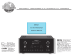
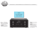
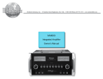
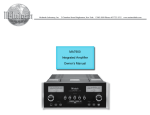
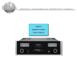
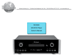
MX121
A/V Control Center
Owner’s Manual
13903-2699 Phone: 607-723-3512
www.mcintoshlabs.com
The lightning flash with arrowhead, within an equilateral
triangle, is intended to alert the user to the presence of
uninsulated “dangerous voltage” within the product’s enclosure that may be of sufficient magnitude to constitute
a risk of electric shock to persons.
WARNING - TO REDUCE RISK
OF FIRE OR ELECTRICAL
SHOCK, DO NOT EXPOSE
THIS EQUIPMENT TO RAIN OR
MOISTURE.
IMPORTANT SAFETY
INSTRUCTIONS!
PLEASE READ THEM BEFORE
OPERATING THIS EQUIPMENT.
1. Read these instructions.
2. Keep these instructions.
3. Heed all warnings.
4. Follow all instructions.
5. Do not use this apparatus near water.
6. Clean only with a dry cloth.
7. Do not block any ventilation openings. Install
in accordance with the manufacturer’s instructions.
8. Do not install near any heat sources such as
radiators, heat registers, stoves, or other apparatus (including amplifiers) that produce heat.
9. Do not defeat the safety purpose of the polarized or grounding-type plug. A polarized plug
has two blades with one wider than the other.
A grounding type plug has two blades and a
third grounding prong. The wide blade or the
2
The exclamation point within an equilateral triangle is
intended to alert the user to the presence of important
operating and maintenance (servicing) instructions in the
literature accompanying the appliance.
NO USER-SERVICEABLE PARTS
INSIDE. REFER SERVICING TO
QUALIFIED PERSONNEL.
third prong are provided for your safety. If
the provided plug does not fit into your outlet,
consult an electrician for replacement of the
obsolete outlet.
10. Protect the power cord from being walked on
or pinched particularly at plugs, convenience
receptacles, and the point where they exit
from the apparatus.
11. Only use attachments/accessories specified by
the manufacturer.
12. Use only with the cart, stand, tripod, bracket,
or table specified by the manufacturer, or sold
with the apparatus. When a cart
is used, use caution when moving the cart/apparatus combination to avoid injury from tipover.
13. Unplug this apparatus during lightning storms
or when unused for long periods of time.
14. Refer all servicing to qualified service personnel. Servicing is required when the apparatus
has been damaged in any way, such as powersupply cord or plug is damaged, liquid has
To prevent the risk of electric
shock, do not remove cover or
back. No user-serviceable parts
inside.
been spilled or objects have fallen into the
apparatus, the apparatus has been exposed to
rain or moisture, does not operate normally, or
has been dropped.
15. Do not expose this equipment to dripping or
splashing and ensure that no objects filled
with liquids, such as vases, are placed on the
equipment.
16. To completely disconnect this equipment from
the a.c. mains, disconnect the power supply
cord plug from the a.c. receptacle.
17. The mains plug of the power supply cord shall
remain readily operable.
18. Do not expose batteries to excessive heat such
as sunshine, fire or the like.
19. Connect mains power supply cord only to a
mains socket outlet with a protective earthing
connection.
20. Warning: The Ethernet connector of this
equipment must not be directly connected
to a public network. Connection is to be
made only by way of a modem or router approved for this purpose.
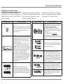
Trademark and License Information
Trademark and License Information
The McIntosh MX121 incorporates copyright protected technology that is protected by U.S. patents and
other intellectual property rights. The MX121 uses the
following Technologies:
Trademark Logo
PANDORA, the PANDORA logo, and the Pandora
trade dress are trademarks or registered trademarks of
Pandora Media, Inc. Used with permission.
This item incorporates copy protection technology
that is protected by U.S. patents and other intellectual
property rights of Rovi Corporation. Reverse engineering and disassembly are prohibited.
License Information
Trademark Logo
AirPlay®, the AirPlay logo, iPhone®, iPod®, iPod classic®, iPod nano®, iPod shuffle®, iPod touch® and iPad®
are trademarks of Apple Inc., registered in the U.S.
and other countries.
“Made for iPod” and “Made for iPhone” mean that
an electronic accessory has been designed to connect
specifically to iPod or iPhone respectively, and
has been certified by the developer to meet Apple
performance standards.
Apple is not responsible for the operation of this
device or its compliance with safety and regulatory
standards. Please note that the use of this accessory
with iPod, or iPhone, may affect wireless performance.
•iPhone, iPod, iPod classic, iPod nano, iPod shuffle
and iPod touch are trademarks of Apple Inc.,
registered in the U.S. and other countries.
Individual users are permitted to use iPhone, iPod,
iPod classic, iPod nano, iPod shuffle,and iPod touch
for private copy and playback of non-copyrighted
contents and contents whose copy and playback
is permitted by law. Copyright infringement is
prohibited by law.
Manufactured under license from Audyssey
Laboratories. U.S. and foreign patents pending.
Audyssey MultEQ® XT, Audyssey Dynamic EQ®,
Audyssey Dynamic Volume® and Audyssey DSX®
are registered trademarks of Audyssey Laboratories.
License Information
DLNA®, the DLNA Logo and DLNA CERTIFIED®
are trademarks, service marks, or certification marks
of the Digital Living Network Alliance.
Device Class: DMP (Digital Media Player)
DLNA Certified® Product Function: FINDS, PLAYS
Content Type: audio, images, videos (Check supported
media formats.)
DLNA consumer website: www.dlna.org
Some content may not be compatible with other
DLNA Certified® products (example: optional media
formats)
Manufactured under license from Dolby Laboratories.
Dolby, Pro Logic and the double-D symbol are trademarks of Dolby Laboratories.
TM
HIGH-DEFINITION MULTIMEDIA INTERFACE
Manufactured under license under U.S. Patent
Nos: 5,956,674; 5,974,380; 6,226,616; 6,487,535;
7,212,872; 7,333,929; 7,392,195; 7,272,567 & other
U.S. and worldwide patents issued & pending. DTSHD, the Symbol, & DTS-HD and the Symbol together
are registered trademarks & DTS-HD Master Audio is
a trademark of DTS, Inc. Product includes software.
© DTS, Inc. All Rights Reserved.
Manufactured under license from DTS Licensing
Limited. DTS, the Symbol, & DTS and the Symbol
together are registered trademarks & DTS Neural
Surround is a trademark of DTS, Inc. Product includes
software. © DTS, Inc. All Rights Reserved.
HDMI, the HDMI Logo and High-Definition
Multimedia Interface are trademarks or registered
trademarks of HDMI Licensing LLC in the United
States and other countries.
3
Thank You
Customer Service
Your decision to own this McIntosh MX121 A/V Control Center ranks you at the very top among discriminating music listeners. You now have “The Best.” The
McIntosh dedication to “Quality,” is assurance that
you will receive many years of musical enjoyment
from this unit.
Please take a short time to read the information in
this manual. We want you to be as familiar as possible with all the features and functions of your new
McIntosh.
If it is determined that your McIntosh product is in
need of repair, you can return it to your Dealer. You
can also return it to the McIntosh Laboratory Service
Department. For assistance on factory repair return
procedure, contact the McIntosh Service Department
at:
Please Take A Moment
The serial number, purchase date and McIntosh Dealer
name are important to you for possible insurance
claim or future service. The spaces below have been
provided for you to record that information:
Serial Number:________________________________
Purchase Date:_ _______________________________
Dealer Name:_ ________________________________
Technical Assistance
If at any time you have questions about your McIntosh
product, contact your McIntosh Dealer who is familiar
with your McIntosh equipment and any other brands
that may be part of your system. If you or your Dealer
wish additional help concerning a suspected problem,
you can receive technical assistance for all McIntosh
products at:
McIntosh Laboratory, Inc.
2 Chambers Street
Binghamton, New York 13903
Phone: 607-723-3512
Fax: 607-724-0549
4
McIntosh Laboratory, Inc.
2 Chambers Street
Binghamton, New York 13903
Phone: 607-723-3515
Fax: 607-723-1917
Table of Contents
Safety Instructions...................................................... 2
Trademark and License Information.......................... 3
Thank You and Please Take a Moment....................... 4
Technical Assistance and Customer Service.............. 4
Table of Contents........................................................ 4
General Information................................................... 5
Connector and Cable Information.............................. 6
Introduction................................................................. 7
Performance Features................................................. 7
Dimensions................................................................. 8
Installation.................................................................. 9
Connections:
Rear Panel Connections............................................ 10
Connections Diagram (Separate Sheet).................. Mc1A
MX121 Main Zone Input Connections..................... 11
Connection Diagram (Separate Sheet)................... Mc2A
MX121 Main Zone Output Connections.................. 12
Connection Diagram (Separate Sheet)....................Mc2B
MX121 Zone 2 Input and Output Connections......... 13
Connection Diagram (Separate Sheet).............Mc3A, 3B
Copyright 2012 © by McIntosh Laboratory, Inc.
Front Panel:
Front Panel Displays, Controls and Push-buttons....147
Diagram (Separate Sheet)........................................Mc1B
Remote Control:
Remote Control......................................................... 15
Push-buttons Functioning (Separate Sheet)....Mc4A, 4B
Setup Mode:
Introduction to the MX121 Setup Mode................... 16
Audyssey Auto Setup........................................... 17-20
Network Settings and Functions.......................... 21-23
Trigger Settings and Option Settings....................... 23
Input Connections, Re-Naming and
Amplifier Assignment........................................... 24
Manual Speaker Setup.............................................. 25
HDMI, Zone 2 and Zone 3 Setup............................. 26
Picture Adjust and IR Sensor Setting....................... 27
Video Input, Input Mode Setup................................ 28
Input Source Level, Audio Setup and
Manual Equalization......................................... 29-30
Surround Parameter.................................................. 30
Operation:
How to Operate the MX121.................................32-49
Audyssey Adjustments............................................. 37-38
iPod Playback and AirPlay.......................................38-39
USB Drive Playback......................................................40
Accessing the Internet and McIntosh Radio........... 42-43
Pandora.................................................................... 44-45
Last.fm..................................................................... 46-47
Flickr..............................................................................48
Resetting the Micro and Updating Firmware................49
Additional Information:
Specifications............................................................ 50
Packing Instruction................................................... 51
General Information
General Information
1. For additional connection information, refer to the
owner’s manual(s) for any component(s) connected to the MX121 A/V Control Center.
2. The Main AC Power going to the MX121 and
any other McIntosh Component(s) should not
be applied until all the system components are
connected together. Failure to do so could result
in malfunctioning of some or all of the system’s
normal operations. When the MX121 and other
McIntosh Components are in their Standby Power
Off Mode, the Microprocessor’s Circuitry inside
each component is active and communication is
occurring between them.
3. Sound Intensity is measured in units called Decibels and “dB” is the abbreviation.
4. LFE (Low Frequency Effects) refers to the Dolby
Digital or DTS sound channel dedicated to sound
effects (such as explosions) and is usually reproduced by the Subwoofer.
5. When discarding the unit, comply with local rules
or regulations. Batteries should never be
thrown away or incinerated but disposed
of in accordance with the local regulations concerning battery disposal.
6. For additional information on the
MX121 and other McIntosh Products
please visit the McIntosh Web Site at
www.mcintoshlabs.com.
7. The Main Zone accepts Audio Input Signals from
the HDMI, iPod/USB, Coaxial/Optical Digital
and unbalanced/balanced Analog Input Connections.
8. The Zones 2 and 3 accept Audio Input Signals
from the iPod/USB, Coaxial/Optical PCM Digital
Signals and unbalanced/balanced Analog Input
Connections.
Note: When connecting source devices with HDMI
Outputs to the MX121, make sure to also connect the unbalanced/balanced Analog Output
or Coaxial/Optical Digital Audio Output for
each HDMI Source connected to MX121.
9. The Main Zone accepts Video Input Signals from
the HDMI, Component Video and Composite
Video Input Connections.
10. Zone 2 accepts Video Input Signals from the
Component Video and Composite Video Input
Connections.
11. Zone 3 is for Audio Signal Sources only.
12. MX121 is a three Zone Product (Main Zone, Zone
2 and Zone 3). This allows two different Audio/
Video Sources to be available simultaneously
for two separate rooms. Zone 2 may be used to
provide an Audio/Video Output Signal for recording purposes, instead of an A/V signal to a second
room. The Zone 3 allows for listening to a different Audio Source from either the Main Zone or
Zone 2. For more information contact your McIntosh Dealer or McIntosh Technical Support.
13. The IR Input with 1/8 inch mini phone jack is
compatible IR sensors such as a Xantech Model
HL85BK Kit. Use a Connection Block such as a
Xantech Model ZC21 when two or more IR sensors need to be connected to the MX121. To avoid
possible interaction, disable the MX121 Front
Panel Sensor. Refer to “IR Sensor" on page 27.
14. Setup Mode operations should be performed in
the order they appear in the first Setup Menu
presented, as they are interactive.
15. To hear bass frequencies below 80Hz, your system
must include either a Subwoofer or Large Front
Loudspeakers.
16. The MX121 has built-in HDMI Digital Video
Selection and Digital Video Processing Circuitry
with scaling capabilities to convert Composite or
Component Video Signals to Digital Video.
17. When there is a connection between the HDMI
Output and a TV/Monitor, the On-Screen Overlays including Menus, will only appear on the
HDMI Output.
18. HDMI Cable lengths between source components
and the MX121 also between the MX121 and the
TV/Monitor, should not exceed 25ft (8.3m). If
there is need to use HDMI Cables longer than 25ft
(8.3m) a high quality in line HDMI Buffer/Converter would be required for reliable digital signal
transmission via the HDMI Connections.
19. The MX121 is designed to pass through a 3D
Digital Video Signal from a source component
to a 3D TV/Monitor via the HDMI Connections.
It is extremely important the HDMI cables used
for connections meet or exceed the HDMI High
Speed Cable Standards (1.4a) for proper 3D Video
Playback.
20. The Remote Control Supplied with the MX121
A/V Control Center is capable of operating other
components. For additional information go to
www.mcintoshlabs.com.
21. The MX121 is compatible with the following
Apple Mobile Devices with the latest version of
the Apple OS Software installed:
iPod touch (4th generation) iPod touch (3rd generation)
iPod touch (2nd generation)
iPod touch (1st generation)
iPod classic
iPod nano (6th generation)
iPod nano (5th generation)
iPod nano (4th generation)
iPod nano (3rd generation)
iPhone 4S
iPhone 4
iPhone 3GS
iPhone 3G
iPhone
5
Connector and Cable Information
Connector and Cable Information
XLR Connectors
Below is the Pin configuration for the XLR Balanced
Output Connectors on the MX121. Refer to the diaOutput
Input
grams for connections:
PIN 1: Shield/Ground
PIN 2: + Signal
PIN 3: - Signal
PIN 1
PIN 2
PIN 2
PIN 1
PIN 3
PIN 3
PWR CTRL (Power Control)/Trigger Connectors
The MX121 Power Control Out/ Trigger Output Jacks
send an On/Off signal from 0 to +12 volts with a total
current up to 50mA when
+12V DC
connected to other Com(Trigger
ponents. A 1/8 inch stereo
Control)
N/C
mini phone plug is used for
connection to the Power
Ground
Control/ Trigger Outputs on
the MX121.
Data In and Output
The MX121 Data In receives
Remote Control Signals from
Data
Signal
Source Components. The
MX121 Data Out sends Remote
Control Signals to McIntosh
Source Components. A 1/8 inch
mini phone plug is used for connection.
IR In Port Connector
The IR IN Port also uses a 1/8
inch mini phone plug and allows the connection of external
IR Receivers to the MX121.
Ground
IR Data
Control
Ground
6
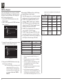
RS232 DB9 Connector Pin Layout
1. N/C
6. N/C
2. Data Out (TXD) 7. N/C
3. Data In (RXD) 8. N/C
4. N/C
9. N/C
5. Gnd.
Ethernet RJ45 Socket
1. Tranceive Data (+)
2. Tranceive Data (-)
3. Receive Data (+)
4. N/C
5. N/C
6. Receive Data (-)
7. N/C
8. N/C
Ethernet Cable - Straight Thru Connections
Pin Number - Wire Color
Pin Number - Wire Color
1. Orange/White
→
1. Orange/White
2. Orange
→
2. Orange
3. Green/White
→
3. Green/White
4. Blue
→
4. Blue
5. Blue/White
→
5. Blue/White
6. Green
→
6. Green
7. Brown/White
→
7. Brown/White
8. Brown
→
8. Brown
Pin 8
Pin 1
Pin 1
Pin 8
Ethernet Cable - Crossover Connections
Pin Number - Wire Color
Pin Number - Wire Color
1. Orange/White
→
1. Green/White
2. Orange
→
2. Green
3. Green/White
→
3. Orange/White
4. Blue
→
4. Blue
5. Blue/White
→
5. Blue/White
6. Green
→
6. Orange
7. Brown/White
→
7. Brown/White
8. Brown
→
8. Brown
Cable Information, Introduction and Performance Features
Introduction
The MX121 A/V Control Center sets the standard of
excellence in a Home Theater System. The MX121
provides superior multichannel reproduction, Audyssey® Room correction, the latest in digital audio
decoding and digital video processing circuitry.
• Built-in Dolby True HD and DTS-HD Master
Decoders
The MX121 also provides built-in decoding of the
Dolby Pro Logic IIz, Dolby Pro Logic IIx, Dolby
Digital EX, DTS Neo6 and DTS-ES Sound Tracks.
Performance Features
• Internet Streaming
The MX121 when connected to a network, offers Internet Radio, with music and photo streaming.
• HDMI 1.4a with 3D Passthru Switching
There are six HDMI 1.4a Inputs. HDMI Output 1 includes the new Digital Audio Return Channel (ARC)
signal from the TV1, thus eliminating the need for an
extra cable and simplifies operation. HDMI inputs are
compatible with Deep Color, x.v.Color, Auto Lipsync
and HDMI Component Control.
• Analog Video/Audio Switching with Scaling
Component Video Inputs and Composite Video Inputs
(Analog Video Signals) are also converted to a Digital
Video Signal with resolution up to 1080P at the HDMI
Outputs.
• Direct Access
There are 9 Analog (one eight channel input) and 11
Digital Audio Inputs along with 9 Analog and 6 Digital Video Inputs.
• Balanced Inputs and Outputs
A pair of Balanced high level Inputs and an eight
channel Balanced Output are provided, permitting
long cable lengths without a loss in sound quality.
• Moving Magnet Phono Input
There is a Precision Phono Preamplifier for Moving
Magnet Cartridges.
1
• On-Screen and Multifunction Fluorescent
Displays
A comprehensive On-Screen Display capability makes
it easy to perform setup and operational adjustments
using the Remote Control. The front panel display
indicates input selection, volume levels, and other
operating functions.
• LED Channel Status Indicators
The MX121 includes twenty-five LEDs on the front
panel to indicate what type of operating signals are
being received, signal processing mode and the output
format chosen.
• Audyssey DSX®
Audyssey DSX is a scalable system that adds new
speakers to improve surround impression.
Audyssey DSX first adds Wide channels for the
biggest impact on envelopment and then creates
Height channels to reproduce the next most important
acoustical and perceptual cues. Surround
Envelopment Processing is used to enhance the blend
between the front and surround channels.
• Digitally Controlled Volume and Tone Controls
A Precision Tracking Volume Control adjusts all
twelve channels with tracking accuracy better than
0.5dB. The Bass and Treble circuits provide a wide
range of tone shaping with no loss in traditional McIntosh sonic excellence.
• Triple Zones
The MX121 has the built-in ability to control a separate remote audio/video zone (Zone 2) with program
selection independent of Main Zone, using a dedicated
power amplifier and speakers. There is also a third
Zone (Zone 3) providing a separate audio only source
to another room.
• Fiber Optic Solid State Front Panel Illumination
The Illumination of the Glass Front Panel is accomplished by the combination of custom designed Fiber
Optic Light Diffusers and extra long life Light Emitting Diodes (LEDs). This provides even Front Panel
Illumination and is designed to ensure the pristine
beauty of the MX121 will be retained for many years.
• Power Control, Triggers and Full Function Remote Control
The Power Control and Triggers provide convenient
Turn-On/Off of components connected to the MX121.
The Remote Control Push-buttons provide complete
control of the MX121 operating functions.
• Machined Side Panels
The sides of the MX121 are machined from thick aluminum panels with a smooth black finish.
• Special Power Supply
The Power Supply has Multiple Regulators to ensure
stable noise free operation even though the power line
varies.
For TVs with ARC compatibly
7
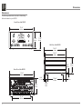
Dimensions
Dimensions
The following dimensions can assist in determining
the best location for your MX121.
Front View of the MX121
17-1/2"
44.5cm
7 -1/8"
18.1cm
7 -5/8"
19.4cm
Side View of the MX121
16-1/2"
41.9cm
14-1/2"
36.8cm
3/16"
0.5cm
6-9/16"
16.7cm
Rear View of the MX121
17-1/8"
43.5cm
13/16"
2.1cm
6-3/8"
16.2cm
13 -1/4"
33.7cm
8
10-9/16"
26.8cm
1-15/16"
4.9cm
2"
5.1cm
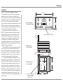
Installation
Installation
The MX121 can be placed upright on a table or
shelf, standing on its four feet. It also can be custom
installed in a piece of furniture or cabinet of your
choice. The four feet may be removed from the bottom
of the MX121 when it is custom installed as outlined
below. The four feet together with the mounting
screws should be retained for possible future use if the
MX121 is removed from the custom installation and
used free standing. The required panel cutout, ventilation cutout and unit dimensions are shown.
Always provide adequate ventilation for your
MX121. Cool operation ensures the longest possible
operating life for any electronic instrument. Do not
install the MX121 directly above a heat generating
component such as a high powered amplifier. If all
the components are installed in a single cabinet, a
quiet running ventilation fan can be a definite asset in
maintaining all the system components at the coolest
possible operating temperature.
When the MX121 is placed free-standing on a flat
surface, allow at least 2 inches (5.08cm) above the
top and 2 inches (5.08cm) on each side, so airflow is
not obstructed. Allow 19-1/2 inches (49.53cm) depth
behind the front panel. Allow 1-7/16 inch (3.66cm) in
front of the mounting panel for knob clearance.
A custom cabinet installation should provide the
minimum spacing dimensions for cool operation. Allow at least 2 inches (5.08cm) above the top, 2 inches
(5.08cm) below the bottom and 2 inches (5.08cm) on
each side, so airflow is not obstructed. The Custom
Cabinet should be open backed and at least 12 inches
(30.48cm) away from any surface such as a wall. Be
sure to cut out a ventilation hole in the mounting shelf
according to the dimensions in the drawing. Allow
1-7/16 inch (3.66cm) in front of the mounting panel for
knob clearance.
17-3/16"
43.7cm
MX121 Front Panel
Custom Cabinet Cutout
6-9/16"
16.7cm
Cutout Opening for Custom Mounting
Cabinet
Front
Panel
MX121 Side View
in Custom Cabinet
Cutout Opening for Ventilation
Support
Shelf
2-1/4"
5.7cm
Chassis
Spacers
9-1/8"
23.2cm
MX121 Bottom View
in Custom Cabinet
15"
Cutout
38.1cm
Opening
for
Ventilation
1-1/16"
Note: Center the cutout Horizontally 2.7cm
on the unit. For purposes of
clarity, the above illustration
is not drawn to scale.
15"
38.1cm
12-5/16"
31.3cm
9
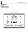
Rear Panel Connections
Rear Panel Connections
The identification of Rear Panel Connections for the
MX121 A/V Control Center is located on a separate
folded sheet contained in the Owner’s Manual Packet.
Refer to separate sheet “Mc1A” for the Rear Panel
Connections.
MX121 A/V Control Center Rear Panel
10
MX121 Main Zone Input Connections
MX121 Main Zone Input Connections
The MX121 has the ability to automatically switch
power On/Off to McIntosh Source Components via
the Power Control/Trigger connections. The Data Port
Connections allow for the remote operation of basic
functions using the MX121 Remote Control. With an
external sensor connected, remote control operation of
the system is possible when the MX121 is located in a
cabinet with the doors closed (Main Zone).
The Main Zone connection instructions below,
together with the MX121 Input Connection Diagram
located on the separate folded sheets “Mc2A”, is an
example of a typical Home Theater System. Your
system may vary from this, however the actual components would be connected in a similar manner. For
additional information refer to “Connector and Cable
Information” on page 6.
Note: The following source component and sensor connections made to the MX121 are using the default
settings. Refer to page 24.
Power Control Connections:
1. Connect a Control Cable from the MX121 PWR
CTRL TRIGGER 1 Jack to the Power Control
Remote In on the Turntable.
2. Connect a Control Cable from the Turntable
Power Control Remote Out jack to the AM/FM
Tuner Power Control In Jack.
3. Connect a Control Cable from the AM/FM Tuner
Power Control Out Jack to the Audio/Video Disc
Player Power Control In Jack.
4. Connect any additional McIntosh Components in
a similar manner, as outlined in steps 1 thru 3.
5. Connect a Control Cable from the Power Control
Output Jack (from the last component a Power
Control Input connection was made) onto the first
Power Amplifier with a Power Control Input jack.
Data Control Connections:
6. Connect a Control Cable from the MX121 DATA
OUT Jack to the AM/FM Tuner Data In Jack.
IR In Connections:
7. Optionally, connect the Control Cable from the
Main Zone External Sensor (or external IR Connection Block) to the MX121 IR IN Jack.
Note: Refer to page 5 for information on compatible Sensors and page 6 for Cable/Connection
information.
Analog Audio Connections:
8. Connect an Audio Cable from the MX121 ANALOG AUDIO IN TUNER Jacks to the Tuner
unbalanced Analog Output Jacks.
9. Connect Balanced Cables from the MX121 AUX
1 BALANCED IN Jacks to the Audio/Video Disc
Player Audio Outputs Balanced 2 CHannel Jacks.
10. Connect an Audio Cable from the MX121 ANALOG AUDIO IN VCR Jacks to the VCR Analog
Output Jacks.
11. Connect Audio Cables from the MX121 ANALOG
AUDIO IN PHONO Jacks to the Turntable Out
Jacks.
Digital Audio Connections:
12. Connect a Digital Coaxial Cable from the MX121
Digital COAX IN 2 Jack to the Satellite Reciever
Digital Coaxial Output Jack.
Analog Video Connections:
13. Connect a Video Cable from the MX121 COMPONENT VIDEO IN 2 Jacks to the Satellite Reciever
Component Video Output Jacks, making sure to
match the “Y”, “PB” and “PR” connections at both
ends of the cable.
HDMI Connections:
14. Connect a HDMI Cable from the MX121 HDMI
IN 1 Connector to the Audio/Video Disc Player
HDMI Out Connector.
Ground Connections:
15. Connect a Ground Cable from the MX121 GND
Binding Post to the Turntable GND Binding Post.
Proceed to Main Zone Output Connections on the
next page.
11
MX121 Main Zone Output Connetions
MX121 Main Zone Output Connections
The MX121 has the ability to automatically switch
power On/Off to a McIntosh Power Amplifier via the
Power Control/Trigger connection.
The connection instructions below, together with
the MX121 Main Zone Output Connection Diagram
located on the separate folded sheet “Mc2B”, is an example of a typical Home Theater System. Your system
may vary from this, however the actual components
would be connected in a similar manner. For additional information refer to “Connector and Cable Information” on page 6.
Note: The following component connections made to
the MX121 are using the default settings. To make
changes to the default settings proceed to Setup
Mode starting on page 16.
Power Control Connections:
1. From the last component a Power Control Input
connection was made to, connect the Control
Cable to the Power Control In on Main Zone
Power Amplifier One.
Note: If no source component(s) is connected for
Power Control from the MX121, then connect
a Control Cable from the PWR CTRL/TRIGGER Jack on the MX121 to the Power Control In on Main Zone Power Amplifier One.
2. Connect a Control Cable from Main Zone Power
Amplifier One Power Control Out to Main Zone
Power Amplifier Two Power Control In Jack.
3. Connect a Control Cable from Main Zone Power
Amplifier Two Power Control Out to Main Zone
Power Amplifier Three Power Control In Jack.
4. Connect a Control Cable from Main Zone Power
Amplifier Three Power Control Out to the Powered Subwoofer Power Control In Jack.
5. Connect any additional McIntosh Components in a
similar manner, as outlined in steps 1 thru 4.
12
Analog Audio Connections:
6. Connect Balanced Audio Cables from the MX121
BALANCED OUTPUTS (Main Zone) - FL (Front
Left Channel), C (Front Center Channel) and FR
(Front Right Channel) to Main Zone Power Amplifier One Inputs 1, 2 and 3 respectively.
Note: Unbalanced Audio Connections may be used
in place of the Balanced Connections.
7. Connect Balanced Audio Cables from the MX121
BALANCED OUTPUTS (Main Zone) - SL (Surround Left Channel) and SR (Surround Right
Channel) to Main Zone Power Amplifier Two,
Inputs Left and Right respectively.
8. Connect Balanced Audio Cables from the MX121
BALANCED OUTPUTS (Main Zone) - SBL
(Surround Left Back Channel) and SBR (Surround
Right Back Channel) to Main Zone Power Amplifier Three, Inputs Left and Right respectively.
9. Connect a Balanced Audio Cable from the MX121
BALANCED OUTPUTS (Main Zone) - SW1
(Subwoofer) to the Powered Subwoofer MONO
Input.
Note: Optionally Connect a second Subwoofer to
the BALANCED OUTPUT (Main Zone) SW2
connection.
HDMI Connections:
10. Connect a HDMI Cable from the MX121 ZA
HDMI OUT 1 ARC Connector to the Main Zone
TV/Monitor HDMI Input Connector.
When Zone 2 (Audio/Video in another room) on the
MX121 will be utilized, proceed to page 13 for information on making the needed additional connections.
If Zone 2 will not be utilized at this time proceed to
step 11 below.
AC Power Cords Connections:
11. Connect the MX121 and any remaining components’ AC Power Cords to a live AC outlet.
MX121 Zone 2 Input and Output Connections
MX121 Zone 2 Input Connections
In a typical MX121 two Zone Audio/Video System,
Source Components can share the same Data Port
Connections. The two Zones of the MX121 also share
the same Analog Audio and Component Video Connections. The additional Analog Audio and Video
Connections below are for Source Components connected to Main Zone via Digital Connections, as Zone
2 is Analog Audio/Video only.
The MX121 Zone 2 Input Connection Diagram (located on the separate folded sheet “Mc3A and Mc3B”)
is an example of a typical Zone 2 Second Room
System. Your system may vary from this, however the
actual components would be connected in a similar
manner. For additional information refer to “Connector and Cable Information” on page 6.
Note: The following connections made to the MX121
are using the default settings. To make changes to
the default settings proceed to Setup Mode starting on page 16.
Sensor Connections:
1. Connect the Zone 2 Sensor to a external IR Connection Block and the output of the Connection
Block to the MX121 IR IN Jack.
Note: If there is no external Sensor used for the
Main Zone, a splitter is not needed. Connect
the Zone 2 Sensor directly to the MX121 IR IN
Jack.
Analog Audio Connections:
2. Connect an Audio Cable from the MX121 ANALOG INPUT IN TUNER Jacks to the AM/FM
Tuner unbalanced Output Jacks.
3. Connect an Audio Cable from the MX121 ANALOG INPUT IN BD Jacks to the Audio/Video
Disc Player Audio Outputs Unbalanced 2CH Jacks.
4. Connect an Audio Cable from the MX121 ANALOG INPUT IN SAT Jacks to the Satellite Analog
Output Jacks.
Analog Video Connections:
5. Connect Component Video Cables from the
MX121 COMPONENT VIDEO IN 1 Jacks to the
Audio/Video Disc Player Component Video Output Jacks, making sure to match the “Y”, “PB” and
“PR” connections at both ends.
6. Connect Component Video Cables from the
MX121 COMPONENT VIDEO IN 3 Jacks to the
Satellite Component Video Output Jacks, making
sure to match the “Y”, “PB” and “PR” connections
at both ends.
MX121 Zone 2 Output Connections
Analog Audio Connections:
3. Connect Audio Cables from the MX121 ANALOG AUDIO OUT Zone 2 OUT Jacks - L (Left
Channel) and R (Right Channel) to Zone 2 Power
Amplifier Left and Right respectively.
Analog Video Connections:
4. Connect Component Video Cables from the
MX121 COMPONENT VIDEO OUT 2/ZONE 2
Jacks to the Zone 2 TV/Monitor Video Input Jacks,
making sure to match the “Y”, “PB” and “PR”
connections at both ends.
AC Power Cords Connections:
5. Connect the MX121 and any remaining components’ AC Power Cords to a live AC outlet.
The MX121 has the ability to automatically switch
power On/Off to McIntosh Power Amplifiers via the
Power Control/Trigger connections.
The following connection instructions, together
with the MX121 Zone 2 Output Connection Diagram
located on the separate folded sheet “Mc3B”, is an
example of a typical Zone 2 Second Room System.
Your system may vary from this, however the actual
components would be connected in a similar manner.
For additional information refer to “Connector and
Cable Information” on page 6.
Note: The following component connections made to
the MX121 are using the default settings.
Power Control Connections:
1. Connect a Control Cable from the MX121 PWR
CTRL/TRIGGER (Power Control) 2 Jack to the
Power Control In on Zone 2 Power Amplifier.
2. Connect any additional McIntosh Components in a
similar manner, as outlined in step 1.
13
Front Panel Display, Controls, and Push-buttons
Front Panel Display, Controls,
and Push-buttons
The identification of the MX121 A/V Control Center Front Panel Display, Controls, and Push-buttons
is located on a separate folded sheet contained in
the Owner’s Manual Packet. Refer to separate sheet
“Mc1B”.
MX121 A/V Control Center Front Panel
14
Remote Control Push-Buttons
Remote Control Push-Buttons
The identification of Remote Control Push-Buttons
for the MX121 A/V Control Center is located on a
separate folded sheet contained in the Owner’s Manual
Packet.
Refer to separate sheet “Mc4A and Mc4B” for Pushbuttons identification.
DFR
HR078
15
Introduction to the MX121 Setup Mode
Introduction to the MX121 Setup Mode
Your McIntosh MX121 has been factory configured
with default operating settings allowing for immediate
use. Changes to the default settings are accomplished
with the built-in Setup Feature using On Screen
Menus.
To assist in navigating the various On Screen
Menus please refer to the set of MX121 Menu separate
folded sheets "MX121-Menu-1 thru Menu-7"; and to
separate sheets “Mc4A thru Mc4B” for Push-button
identifications. These separate sheets are contained in
the Owner’s Manual Packet.
Follow the sequence of SETUP Adjustments as
they appear in this Owner's Manual, as they are
interactive. Some of these adjustments and whether
or not some choices even appear On-Screen are based
on the components connected to the MX121, Source
Input selected and previous
settings made.
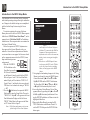
1. Press the STANDBY/
ON Push-button on the
Front Panel or press the
Figure 1
ON (Power) Push-button
on the Remote Control to switch On the MX121.
Refer to figures 1 and 3. The Front Panel Information Display will first indicate “MX121 A/V
Control Center ” and then the last source selected
“BD Stereo” and volume level setting of "M.VOL.
---.-dB".
2. Press the
Push-button, then press the MENU
Push-button to enter the Setup Mode. The words
“*MENU A/V Adjust ” will appear on the Front
Panel Information Display and the On-Screen
"MENU" (Main Menu) will appear on the Monitor/TV Screen. Refer to figure 2.
Notes: 1. While Setup adjustments can be accomplished using the Front Panel Informa-
16
MENU
Audio/Video Adjust
Information
Auto Setup
Manual Setup
Input Setup
Adjust various audio and video parameters
Figure 2
tion Display, the On-Screen Display on
a Monitor/TV connected to the HDMI or
Component Video output allows more
information to be visible at the same time,
making it easier to navigate through the
choices.
2. When there is a HDMI Output Connection between the MX121 and a TV/Monitor, the On-Screen Overlays including
Menus, will only appear on the HDMI
Output.
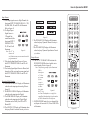
3. Navigating thru and making changes to the Setup
Menus is performed by using the HR078 Remote
Control directional Up or Down, Left or
Right, ENTER and the MENU Push-buttons.
The Front Panel NAV (up), (down), (left)
or (right) Push-buttons may also be used.
4. Access the desired Setup Menu or Device Management (Menu) by pressing the Up or Down
left or right directional push-buttons. Pressing the ENTER Push-button will then activate the
highlighted Menu Item.
5. Return to the Main Menu by pressing the RETURN Push-button on the Remote Control. To
exit the SETUP Mode press the RETURN Pushbutton again.
DFR
HR078
Figure 3
Setup Mode
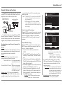
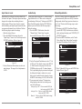
Audyssey® Auto Setup Information
The acoustic characteristics of the connected speakers and listening room are measured and the optimum
settings are made automatically.
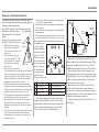
Assemble the supplied setup microphone and stand,
then place it in the main listenSetup Microphone
ing position. Refer to the adjacent
figure.
Keep the following things in mind
during the Audyssey procedure: Sound
1. When placing the setup micro- receptor
phone, adjust the height of the
sound receptor to the level of the
listener’s ear.
2. When performing Audyssey
Auto Setup, MultEQ® XT/ Audyssey Dynamic EQ®/ Audyssey
Microphone
Dynamic Volume® functions
Stand
become active.
3. Make the room as quiet as possible. Background noise can disrupt the room measurements. Close windows, silence cell phones, televisions,
radios, air conditioners, fluorescent lights, home appliances, light dimmers, or other devices as measurements may be affected by these sounds.
4. Cell phones should be placed away from all audio
electronics during the measurement process as Radio
Frequency Interference (RFI) may cause measurement
disruptions (even if the cell phone is not in use).
5. Do not unplug the setup microphone from the main
unit until Audyssey Auto Setup is completed.
6. Do not stand between the speakers and setup microphone or allow obstacles in the path while the measurements are being made. This will cause inaccurate
readings.
7. Loud test sounds may be played during Audyssey Auto
setup. This is part of normal operation. If there is
background noise in the room, these test signals will
increase in volume.
8. Do not adjust Volume during the measurements as this
will cancel the measurements.
9. Measurement cannot be performed when headphones
are connected.
10. Do not hold the setup microphone in your hand during
measurements.
11. Avoid placing the setup microphone close to a seat back
or wall as sound reflections may give inaccurate results.
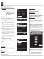
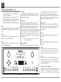
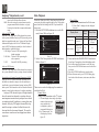
Measurements will be performed by placing the setup
microphone succesFL SW C
FR
sively at multiple
positions throughout the entire listening area. For best
results, we recommend you measure
in six or more positions, as shown in
SL
SR
*M
the illustration (up
to eight positions)
SBL
SBR
about the main
listening position (*M).
FL
Front speaker (L)
SL
FR
Front speaker (R)
SR Surround speaker (R)
C
Center speaker
SBL Surround back speaker (L)
SW Subwoofer
Surround speaker (L)
SBR Surround back speaker (R)
The main listening position is the position where
listeners would normally sit or where one would normally sit alone within the listening environment. The
ideal Loudspeaker Placement in a room for the best
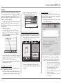
sonic effect is in the Side View Illustration:
Front Height
Loudspeaker
Surround Back
Loudspeaker
Surround
Loudspeaker
A
B
45˚
Front
Loudspeaker
Front Wide
Loudspeaker
Side View
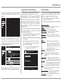
Both the Front Height and Surround Back Loudspeakers should be pointed slightly downward. Dolby
recommends the A dimension be at least 3.3ft (1m).
The B dimension should be between 2-3ft (60-90 cm).
Before starting Audyssey Auto Setup, place the
setup microphone in the main listening position. Audyssey MultEQ® XT uses the measurements from this
position to calculate speaker distance, level, polarity,
and the optimum crossover value.
When using a Powered Subwoofer(s) adjust the
controls on the Subwoofer for neutral settings, as
Audyssey will be making the adjustments of volume,
crossover frequency, etc. Refer to the Subwoofer Owners Manual for additional information.
Proceed to "Audyssey Auto Setup Procedure" on
the next page.
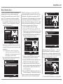
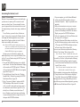
17
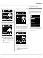
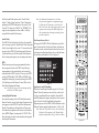
Audyssey® Auto Setup Procedure
With the MX121 connected to a TV/Monitor, the supplied microphone connected to the SETUP MIC Jack
on the Rear Panel and placed in the "Main Listening
location" perform the following steps along with the
instructions appearing On-Screen:
1. Press the
Push-button, then press the MENU
Push-button.
2. Using the Remote Control Directional Push-buttons select first "Auto Setup" followed by "Audyssey Auto Setup. Refer to the illustration below.
AUTO SETUP
AUDYSSEY AUTO SETUP
MultEQ XT
[1/6]
STEP1 Preparation
Connect the speakers
and place them according to the recommendations in the manual.
Set the following
items if necessary.
Amp Assign
Channel Select
Auto Setup Start
Start Auto Setup
ENTER
Enter
RETURN Cancel
Note: If your system contains less than 7.1 channels please refer to "Amp Assign" on page 24
before proceeding.
3. Press the ENTER Push-button to start the Audyssey Auto Setup Process. A test tone will be sent to
all channels, one at time to identify the channels
making up your system.
Notes: 1. Depending on the number of channels in
your system the illustrations in this Owner's
Manual might differ from the actual OnScreen Graphics.
2. During the setup process On-Screen error
messages may appear, if they do refer to page
20 for assistance.
18
4. With the word "Measure" highlighted On-Screen
press the ENTER Push-button to start the Measurement Process. A special audio test signal will
be sent to all previously detected channels, one at
a time. Refer to the illustration below.
AUTO SETUP
AUDYSSEY AUTO SETUP
MultEQ XT
MultEQ XT
[3/6]
STEP3 Measurement
Measurements finished.
ENTER Enter
RETURN Cancel
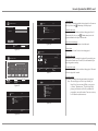
Go to Step 3 (Measurement) after speaker check
Audyssey System will take measurements from eight
different locations in the room to achieve the best
possible sonic results. The additional measurement
locations are indicated by the small bars "▬" in the
room illustration, placed around the sitting area and
the Main sitting position is indicated by an asterisk/
letter m "*M". Refer to page 17.
5. Following the On-Screen instructions place the
microphone in the 2nd listening position and then
press the ENTER Push-Button to select highlight
"Measurement". Refer to the illustration below.
STEP3 Measurement
Please place the microphone at ear height
at 2nd listening
position.
AUTO SETUP
AUDYSSEY AUTO SETUP
[2/6]
STEP2 Spkr Detect Check
Front
Yes
Center
Yes
Subwoofer
Yes
Surround
Yes
S.Back
2spkrs
F.Height
No
F.Wide
No
Retry
Next
Measurement
AUTO SETUP
AUDYSSEY AUTO SETUP
6. Continue following the On-Screen instructions
repeat the measurement process as outlined in
step 5 until all eight listening positions have been
measured. The On-Screen message will now indicate the measurements are finished. Refer to the
illustration below:
Retry
Next
Calculation
ENTER Enter
Proceed to Step 4 (Analyze)
RETURN Cancel
7. Using the Remote Control Directional Push-Button select "Next Calculation" then press the ENTER Push-button. Refer to the Illustration below:
AUTO SETUP
AUDYSSEY AUTO SETUP
STEP4 Calculation
Now calculating...
Please wait.
MultEQ XT
[4/6]
25%
MultEQ XT
[3/6]
Measure
Next
Calculation
ENTER Enter
RETURN Cancel
Start next measurement. Test Tone will start
It will now take some time to process all the measurements made and arrive at the corrections necessary
for each of the connected speakers to achieve the best
possible sonic results.
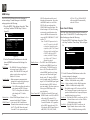
Setup Mode, con't
Audyssey® Parameter Check
Refer to the illustration below:
AUTO SETUP
AUDYSSEY AUTO SETUP
MultEQ XT
[5/6]
STEP5 Check
Check processing results. To proceed,press
“Next”
Spkr Config Check
Distance Check
Ch. Level Check
Crossover Check
Next
AUTO SETUP
AUDYSSEY AUTO SETUP
MultEQ XT
[6/6]
STEP6 Store
Now storing...
Please wait.
ENTER
Enter
RETURN Cancel
8. With "Next Store" highlighted press the ENTER
Push-button. Refer to the illustration below:
AUTO SETUP
AUDYSSEY AUTO SETUP
MultEQ XT
STEP6 Store
Press “Store” to store
calculation results.
[6/6]
Store
ENTER Enter
Apply and store measurement result
Note: If the measuring results are not to be saved,
press the RETURN Push-button and a message
“Cancel Auto Setup?” will be displayed. Press
,then select “Yes”. All the measured Audyssey
Auto Setup data will be erased.
AUTO SETUP
PARAMETER CHECK
Restore
10. Referring to the illustration below with "No" highlighted, press the ENTER Push-button. For more
information about Audyssey Dynamic Volume®
together with other Audyssey Operational Functions refer to page 37 in the "How to Operate"
section of this Owner's Manual.
AUTO SETUP
AUDYSSEY AUTO SETUP
RETURN Cancel
Once the Setup Process has been completed, the
Parameter Check Function becomes available. From
the On-Screen Main menu first select "Auto Setup"
followed by "Parameter Check". Refer to the illustration below:
Speaker Config Check
Distance Check
Channel Level Check
Crossover Check
EQ Check
25%
Store
Select item to check
9. With "Store" highlighted again, press the ENTER
Push-button. Saving the results requires about 10
seconds. Refer to the illustration below:
Show speaker configuration result
1. Using the Remote Control Directional Push-buttons, select the desired Parameter and follow the
On-Screen Instructions.
MultEQ XT
Finish
Storing complete.
Auto Setup is now
finished. Please unplug
microphone.
[6/6]
Turn on Dynamic Volume?
Yes
No
ENTER Exit
Turn Dynamic Volume on and exit Auto Setup
Note: Audyssey Auto Setup procedure will need to be
performed again, when changes are made to the
number of Loudspeakers, their replacement in
the room or changes to the Subwoofer(s) Operational Controls.
19
Audyssey® Parameter Check
An error message is displayed if the Audyssey Auto
Setup could not be completed due to speaker placement, the measurement environment, etc. If this happens, check the relevant items, make any necessary
corrective measures, then perform Audyssey Auto
Setup over again.
On-Screen Display
AUTO SETUP
AUDYSSEY AUTO SETUP
MultEQ XT
Caution!
No microphone or Speaker
Retry
Check cause of problem!
AUTO SETUP
AUDYSSEY AUTO SETUP
RETURN Cancel
MultEQ XT
Caution!
Ambient noise is too high
or Level is too low
Retry
Check cause of problem!
RETURN Cancel
Error Details
The connected setup microphone
is broken, or a device other than
the supplied setup microphone is
connected.
Corrective Measures
Connect the included setup microphone to
the SETUP MIC jack of this unit.
Check the speaker connections.
Not all speakers could be detected.
The front L speaker was not properly detected.
There is too much noise in the
Either turn off any device generating
room for accurate measurements to noise or move it away.
be made.
Perform again when the surroundings are
Speaker or subwoofer sound is too quieter.
low for accurate measurements to
be made.
Check the speaker installation and the
direction in which the speakers are facing.
Adjust the subwoofer’s volume.
AUTO SETUP
AUDYSSEY AUTO SETUP
MultEQ XT
Caution!
Front R
None
The displayed speaker could not be
detected.
Turn off the power before checking
speaker connections.
Check the connections of the displayed
speaker.
Retry
Check cause of problem!
AUTO SETUP
AUDYSSEY AUTO SETUP
RETURN Cancel
MultEQ XT
Caution!
Front L
Phase
Retry
Skip
Check cause of problem!
20
RETURN Cancel
The displayed speaker is connected Check the polarities of the displayed
with the polarities reversed.
speaker.
For some speakers, this error message
may be displayed even if the speaker is
properly connected. If you are sure the
connection is correct, press to
select “Skip”, then press ENTER.
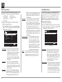
Setup Mode, con't
Network Settings and Functions
An example of a typical home network connected
to the MX121 for access to the internet, your system
might vary from this. Refer to figure below.
Internet Access Device
(Cable Box or DSL Box, etc.)
MX121 Rear Panel
(Partial View)
Computer
(With Network Connection)
Network Router
(Wired or Wireless)
For additional information about PC Internet WEB
Browser Programs, Computers, PC Network Connections and Settings, please refer to the documentation
supplied with your computer and network hardware.
Broadband Internet and Network Connection Requirements
Modem:
Device that connects to the broadband circuit and conducts communications on the Internet. Routers with
an integrated modem are also available.
Router:
With the MX121 we recommend using a router
equipped with the following functions:
Built-in DHCP server - This function automatically
assigns IP addresses on the
LAN.
Built-in 100BASE-TX switch - When connecting multiple
devices, we recommend a
switching hub with a speed
of 100 Mbps or greater.
Ethernet cable: (CAT-5 or greater recommended)
Use only shielded STP or ScTP LAN cable which is
available at retailer. Some flat type Ethernet cables
are easily affected by noise. We recommend using a
normal type cable.
Notes: 1. With the MX121, it is possible to use the DHCP
and Auto IP functions to make the network settings automatically.
2. When using the MX121 with the broadband
router’s DHCP function enabled, this unit automatically performs the IP address setting and
other settings.
Network Automatic Functioning
When the MX121 is connected to a network consisting
of DHCP compliant devices and the internet service
provider is also DHCP compliant, no user manual
settings in the MX121 need to be made for normal
operations.
Network Manual Settings
When the MX121 is connected to a network with no
DHCP Functions the following settings for the IP address, etc., will need to be made:
1. Connect the LAN cable then switch On the
MX121.
2. Press the MENU Push-button, then select "Manual Setup", "Network Setup", "Network Connecting".
3. Using the Directional Push-buttons highlight the
"Detail" Push-button then press the ENTER Pushbutton. Refer to figure 10.
4. With DHCP highlighted use the Directional Pushbuttons to select OFF. Refer to figure 11.
5. Using the Directional Push-buttons to select "IP
Address" followed by the IP Address entry field.
Enter the number IP Address Number then press
the ENTER Push-button.
IP Address: Set the IP address within the ranges
shown below. The Network Audio
MANUAL SETUP NETWORK SETUP
NETWORK CONNECTING
DHCP
IP Address
ON
Exit
Detail
ENTER Enter
Set IP address and proxy manually
RETURN Return
Figure 10
MANUAL SETUP NETWORK SETUP
NETWORK CONNECTING
DHCP
IP Address
Subnet Mask
Default gateway
Primary DNS
Secondary DNS
OFF
[192.168.100.019]
[255.255.255.000]
[000.000.000.000]
[000.000.000.000]
[000.000.000.000]
Proxy
Exit
ENTER Enter
Set if using proxy server
RETURN Return
Figure 11
function cannot be used if other IP addresses are set.
CLASS A: 10.0.0.0 – 10.255.255.255
CLASS B: 172.16.0.0 – 172.31.255.255
CLASS C: 192.168.0.0 – 192.168.255.255
6. If the Subnet Mask, Default gateway, Primary
DNS, and/or Secondary DNS settings need to be
changed at this time enter them like the IP Address was entered.
Subnet Mask: When connecting an xDSL modem or
terminal adapter directly to this unit,
input the subnet mask indicated in the
documentation supplied by your provider. Normally input 255.255.255.0.
Default Gateway: When connected to a gateway
(router), input its IP address.
21
Network Settings and Functions, con't
Primary DNS and If there is only one DNS address
Secondary DNS: indicated in the documentation supplied by your provider, input it at
“Primary DNS”. If there are two or
more DNS addresses, input the first
one at “Primary DNS”.
Network Proxy Settings
When the MX121 is to be connected to the Internet
via a proxy server perform the following:
1. Press the MENU Push-button, then select "Manual Setup", "Network Setup", "Network Connecting".
2. Using the Directional Push-buttons highlight the
"Detail" Push-button then press the ENTER Pushbutton.
3. With DHCP highlighted use the Directional Pushbuttons to select OFF. Then select "Proxy" and
press the ENTER Push-button. Refer to figure 11.
4. Select Proxy "ON" by using the Directional Pushbuttons. Refer to figure 12.
5. Using the Directional Push-buttons to select "Address" and then the "Name" and enter the information.
6. Enter the Proxy Server Port Number.
7. Select "EXIT" and then press the ENTER pushbutton.
Other Network Settings
Refer to figure 13 to make additional settings:
Network Standby:
Allows the MX121 to continue a Network Connection with a compatible controller when in the Standby
Mode.
PC Language:
Allows the MX121 computer environment to be displayed in the desired language.
22
MANUAL SETUP NETWORK SETUP
NETWORK CONNECTING
DHCP
IP Address
Subnet Mask
Default gateway
Primary DNS
Secondary DNS
OFF
[192.168.100.019]
[255.255.255.000]
[000.000.000.000]
[000.000.000.000]
[000.000.000.000]
Proxy
Exit
ENTER Enter
Set if using proxy server
RETURN Return
Figure 11
MANUAL SETUP NETWORK SETUP
NETWORK CONNECTING
Proxy
Proxy
Address
Port
ON
Address
[000.000.000.000]
[00000]
Exit
Friendly Name Edit:
Allows the renaming of "McIntosh MX121" as the
name appears on the computer network.
Update Notification:
Allows the MX121 to display (default setting) "Firmware Update" on the Front Panel Information Display
for about 20 seconds when first switched On.
Update Notification:
Allows the MX121 to display (default setting) "Add
New Feature" on the Front Panel Information Display
for about 20 seconds when first switched On.
Computer Control of the MX121 via the Network
From the Network Information Menu-Screen note the
IP Address for the MX121. Enter the IP number on the
URL Address Line in the Web Browser after "http://".
Then press the Computer Keyboard "Enter" Key, figure 14 should appear several moments later.
http://_ _._ _. _ _ _._ _/index.asp
RETURN Return
Proxy server is used
Figure 12
File
Edit View
Favorites
Tools
Help
INDEX
McIntosh Web Controller
MX121
MAIN ZONE
Status
-25.0dB
MANUAL SETUP
OTHER
NETWORK SETUP
Status
Status
Network Standby
PC Language
Friendly Name Edit
Update Notification
Upgrade Notification
ZONE2
-25dB
ZONE3
-60dB
Setup Menu
PDA Menu
Wed Control Config.
Figure 14
Set network function during standby
Figure 13
From this point forward, the MX121 Setup Functions
will be carried out using the computer. Any Monitor/TV connected to a Video Output Connector the
MX121 will only display the "McIntosh Logo".
Setup Mode, con't
Click on the "Setup menu" on the computer screen and
the Main Setup On-Screen Menu will appear. Refer to
figure 15.
Please select the menu
SETUP MENU
SOURCE SELECT
AUDIO/VIDEO ADJUST
MANUAL SETUP
INFORMATION
SAVE
LOAD
Figure 15
Then click on "Source Select" and figure 16 will appear indicating the current settings for the DVD Input.
Any input can be selected by clicking on the Source
Box Field pull-down indicator.
SOURCE SELECT ReLoad
SETUP MENU
SOURCE SELECT
AUDIO/VIDEO ADJUST
MANUAL SETUP
INFORMATION
SAVE
LOAD
Source DVD
Input Assign
Video
Video Select SOURCE
Video Mode
Auto
Video Convert
ON
i/p Scaler
Resolution(analog)
Resolution(HDMI)
Progressive Mode
Aspect
Game
Movie
OFF
Analog Analog & HDMI
OFF
Auto 480p/576p 1080i
720p
Auto 480p/576p 1080i
720p
AUTO
VIDEO1 VIDEO2
Full
Normal
1080p
1080p
0 dB < Set
Source Level(digital)
0 dB < Set
<
The MX121 has two Trigger/PWR CTRL (Power
Control) Output Connections. They can be set to
provide On (+12V) / Off (0V) Signal when the MX121
is On/Off (Main Zone, Zone 2 or Zone 3), when a specific Input Source is selected or when a TV/Monitor
connected via HDMI to the MX121 switches On/Off.
These signals are used to control Source Components,
Power Amplifiers, or TV/Monitors connected to the
HDMI Outputs, etc.
To change from the default setting of Triggers 1&2 On
when any Zone (Main, Zone 2 or Zone 3) is switched
On, perform the following:
1. Press the MENU Push-button, then select "Manual Setup", "Other Setup", "Trigger Out".
2. Use the Directional Push-buttons to select Trigger
1 or Trigger 2.
3. Then select either a given Zone, a given Input
Source or HDMI Output 1 or 2 to activated the
previously selected trigger.
The MX121 has various options affecting the display
of sound and visual information. Perform the following to make changes from the default settings:
1. Press the MENU Push-button, select "Manual
Setup", then "Other Setup".
2. Use the directional push-buttons to affect changes.
Note: To return the Triggers to the default setting
select the On-Screen "DEFAULT".
1080p:24Hz
1080p:24Hz
Set Def
Source Level(analog) <
Option Settings
MANUAL SETUP OPTION SETUP
TRIGGER OUT
Input Mode
Input Mode Auto
Decode Mode Auto
Rename DVD
Trigger (Power Control) Settings
Trigger Out 1
Trigger Out 2
Default
Figure 16
To end Computer Control of the MX121 switch to another URL Address or close down the Web Browser.
Select operating conditions for trigger out 1
Figure 17
VOLUME CONTROL:
Relative --- Display indicates set in dBs from -80.5 to +18.
Absolute --- Display indicates 0(min)-99.
Volume Limit --- Off, -20dB, -10dB and 0dB.
Power On Level --- Last (volume setting), 0 (muted) or
-80dB to -18dB (1-99).
Mute Level --- Full mute (no sound), -40dB or -20dB.
Source Delete --- Remove from selections a given Input(s).
GUI:
Screen Saver --- Blanks the On-Screen display approximately 3 minutes after user activity stops
when viewing the Setup Menu or NET/
USB/iPod source is selected. Other choice
is Screen Saver disabled.
Wall Paper --- Display the McIntosh Logo (picture) or
blank (black background).
Text --- ON, indicates details of the selected Input and
Surround Mode, etc. .OFF, the information is not
displayed.
Master Volume --- Displays the volume information at
bottom or top of the screen, or not at all.
NET/USB --- Selects the duration of the displayed information (always, 30 seconds, 10 seconds or Off)
when the NET/USB Input is first selected.
iPod --- Selects the duration of the displayed information
(always, 30 seconds, 10 seconds or Off) when the
iPod Input is first selected.
Component 2 Output --- Select the video output between
the Main Zone or Zone 2.
Zone Rename --- Allow renaming of the Zones (up to ten
characters long).
23
Default Input Connection Assignments
The MX121 has the most commonly used Inputs
preassigned to HDMI, Digital Coaxial/Optical and
Component Video (Analog) connections. There
are also permanently assigned Analog Audio and
Video connections. Please refer to the MX121 Menu
separate folded sheet "Menu-7".
Default Input Connection Assignment
Input
Name
HDMI
(Video/Audio)
Audio
(Digital)
Video
(Analog)
BD
HDMI-1
-
Component-1
DVD
HDMI-2
Coaxial-1
Component-2
VCR
HDMI-4
-
Component-4
SAT
HDMI-3
Coaxial-2
Component-3
GAME
HDMI-5
-
-
AUX1
HDMI-6
Optical-3
-
NET/USB
-
-
-
TV
-
Optical-1
-
CD
-
Optical-2
-
CDR
-
-
-
PHONO
TUNER
If there is a desire to reassign input connections
proceed to "Input Connection Re-Assignment". Input
names may also be changed, refer to Renaming
Inputs on this page.
Input Connection Re-Assignment
The HDMI, Digital Coaxial/Optical and Component
Video (Analog) Input Connections can be reassigned
to match up with the components in your A/V
System. To speed up the reassignment process make
a list of the desired changes. A blank reassignment
chart has been provide on the MX121 Menu separate
folded sheet "Menu-7" for this purpose.
Notes: 1. The PHONO, TUNER and NET/USB Inputs
by their nature do not require HDMI, Digital
24
Input Re-Naming
Audio or Video Connections and therefore are
not re-assignable.
2. A given connection type/number can only be
assigned to one Input Name.
3. First switch a given connection type/number
to "NONE" before re-assigning it to a different Input Name.
Make assignment changes by performing the
following:
1. Press the MENU Push-button, then select "Input Setup" and then "Input Assign". Refer to
figure 18.
INPUT SETUP
INPUT ASSIGN
Default
[HDMI]
None
[COMP]
BD
DVD
VCR
SAT
GAME
AUX1
TV
HDMI1
HDMI2
HDMI4
HDMI3
HDMI5
HDMI6
None
None
Coax1
None
Coax2
None
Opt3
Opt1
1-RCA
2-RCA
4-RCA
3-RCA
None
None
None
Select
ENTER Enter
RETURN Return
Assign HDMI 6 input connector assignment
Figure 18
2. Use the Directional Push-buttons to select and the
ENTER Push-button to change the current setting.
3. First select the Input to be changed.
4. Then select the HDMI, DIGITAL or COMP column.
5. Press the ENTER Push-button and then select
from one of the available connections.
6. Press the ENTER Push-button to make the
change.
7. In a similar manner make any additional changes.
The MX121 default Input Names may be changed as
desired. The new Input Name(s) will appear on the
MX121 Front Panel Information Display and on the
TV/Monitor.
To change the Input Name perform the following:
1. Press the MENU Push-button, then select "Input
Setup" and then "Rename". Refer to the MX121
Menu separate folded sheet "Menu-7".
2. Use the Directional Push-buttons to select the
Input.
3. Using the On-Screen Keyboard, enter the new
name and press the ENTER Push-button.
The Front Panel Input Control, the INPUT on
the Remote Control and the On-Screen Incon Control
all allow selection of the Renamed Input.
Amplifier Assignment
The MX121 Amplifier Assigment allows the use of
the Balanced Surround Back Channel Outputs to be
used instead as Balanced Audio Outputs for Zone
2 or Zone 3. They can be used for Bi-Amp (spkr-c
mode) of the Front Left and Right Channels. The
Front L&R are Low Pass Outputs and the Surround
Back Channels are Hi Pass Outputs for the Front
Right and Left Channels.
To change the Amp Assign perform the following:
1. Press the MENU Push-button, then select "Manual Setup", "Speaker Setup" and then "Amp Assign".
2. Use the Directional Push-buttons to select "Zone2,
Zone3 or SPKR-C".
3. Press the RETURN Push-button for the change to
occur.
4. Switch the MX121 OFF and connect the Power
Amplifier(s) to the MX121 to reflect the changes
made.
Setup Mode, con't
Manual Speaker Setup
The MX121 with built-in Audyssey® automatically
performs all the necessary speaker settings and
corrects for the undesirable room acoustic. Refer to
page 17. If for some reason you desire to manually
enter all the speaker settings perform the following:
1. Press the MENU Push-button, then select "Manual Setup", "Speaker Setup" and then "Speaker
Config". Refer to figure 19.
MANUAL SETUP SPEAKER SETUP
SPEAKER CONFIG
Front
Center
Subwoofer
Surround
S. Back
F. Height
F. Wide
Small
Small
Yes
Small
Small
2spkrs
Small
Small
MANUAL SETUP
DISTANCE
RETURN Return
Select front speaker size
Figure 19
2. Following the instruction On-Screen, use the Directional Push-buttons to enter the speaker config
information.
Note: Loudspeaker are consider "Large" when
response goes down to at least 40Hz (-3dB).
Loudspeakers not capable of response down to
40Hz (-3dB) are consider "Small".
3. Press the RETURN Push-button and then select
"Bass Setting". Refer to figure 20.
MANUAL SETUP
BASS SETTING
SW Mode
LPF for LFE
When the Front Speakers are Large, the Low Frequency Audio Signal is reproduced just by the Front
Loudspeakers. The Subwoofer reproduces the LFE
(Low Frequency Effect) Signal plus any Low Frequency Signals not reproduced by Small Speakers in the
System. When the Bass Setting is set to "LFE + Main"
the Low Frequencies reproduced by the Front Speakers will also be reproduced by the Subwoofer.
4. Set the SW Mode to the desired setting.
5. Select the "LPF for LFE" and set the LPF to the
Highest Frequency Signal reproduced by the Front
Large Speakers and is also sent to the Subwoofer.
6. Press the RETURN Push-button and then select
"Distance" Setting. Refer to figure 21.
SPEAKER SETUP
LFE
120Hz
RETURN Return
Play bass of Small speakers & LFE from SW
Figure 20
Unit
Step
SPEAKER SETUP
MANUAL SETUP SPEAKER SETUP
CHANNEL LEVEL
Front L
F. Height L
Center
F. Height R
Front R
F. Wide R
Surround R
S. Back R
0.0dB
0.0dB
0.0dB
0.0dB
0.0dB
0.0dB
0.0dB
0.0dB
RETURN Return
Select speaker and adjust volume
Figure 22
MANUAL SETUP SPEAKER SETUP
CROSSOVER FREQUENCY
Crossover
80Hz
[1/2]
Feet
1ft
Default
Front L
Front R
Center
Subwoofer
12.0ft
12.0ft
12.0ft
12.0ft
ENTER Enter
Return settings to the default
Figure 21
RETURN Return
Set crossover for all each speaker
Figure 23
RETURN Return
7. Measure and enter the distance from the main
listening/viewing to each of the speakers.
8. Press the RETURN Push-button and then select
"Channel Level" Setting. Refer to figure 22.
9. Using an accurate Sound Pressure Meter, measure the test signal coming from the speakers and
make adjustments to achieve the same level for
each of the speakers.
10. Press the RETURN Push-button and then select
"Crossover Frequency" Setting. Refer to figure 23.
If there are speakers in the system considered small
and they have the same Low Frequency Response
(-3dB point) then set the "Crossover _ _ _Hz" setting to that frequency. When there are speaker(s)
with different Low Frequency Responses, select the
"Crossover Advanced" setting. Then set the crossover
frequency accordingly. Refer to figure 24.
MANUAL SETUP SPEAKER SETUP
CROSSOVER FREQUENCY
Crossover
Advanced
Front
Center
Surround
Surround Back
100Hz
100Hz
40Hz
40Hz
Set crossover for all each speaker
RETURN Return
Figure 24
11. Press the MENU Push-button to exit Setup Mode.
25
HDMI Setup
The MX121 HDMI Setup allows the changing of
various settings. To make changes to the default
settings perform the following:
1. Press the MENU Push-button, then select "Manual Setup" and then "HDMI Setup". Refer to
figure 25.
MANUAL SETUP
HDMI SETUP
RGB Range
Auto Lip Sync
HDMI Audio Out
Monitor Out
HDMI Control
Standby Source
Power Off Control
Normal
ON
AMP
Monitor 1
ON
Last
All
RETURN Return
Use video range from 16 (black) to 235 (white)
Figure 25
2. Use the Directional Push-buttons to select the
desired HDMI Function and the Setting to be
changed.
RGB Range --- The NORMAL Setting will produce a
video range from 16 (black) to 235
(white). The ENHANCED Setting will
produce a wider video range from 0
(black) to 255 (white).
Auto Lip Sync --- Makes automatic compensation for
timing shift in audio and video output.
The choices are ON and OFF.
HDMI Audio Out --- The AMP setting allows the audio to
play through the MX121 System.
The TV setting allows the Audio to
play through the TV's Audio
System.
Monitor Out --- Selects HDMI Output Monitor 1 or 2 as
connected to the Main TV/Monitor.
HDMI Control --- Activates the ARC (Audio Return
Channel) when connected to a compat ible TV. The ARC allows the sound
from the TV to be processed by the
26
MX121 without the need for an additional cable connection. Also when
the HDMI Control is set to ON the
MX121 will pass on through the
HDMI Cable Control Functions. The
default setting is OFF, the ON setting
activates the control function when
there is a HDMI cable connected between the MX121 HDMI OUT 1 ARC
and the TV.
Note: The MX121 Input needs to be
set to TV, in order for the ARC
to function. Depending on the
capability of the TV the Control
Functions might include Power
ON/OFF, adjust the MX121
volume, select MX121 Inputs,
etc. Refer to the TV Owner's
Manuals for details.
Standby Source --- The MX121 has a HDMI pass-thru
mode when the HDMI Control is set
to ON and the TV HDMI Control is
also set ON. This allows the MX121
selected HDMI Input Source Component to pass its Video/Audio Signal
directly to the TV when the MX121
is in the standby mode. The default setting of LAST is the HDMI Input Signal
last selected on the MX121 before it
goes into standby. The other option is to
select a given HDMI Input as the
pass-thru choice.
Power Control Off --- With Power Control Off active and
HDMI Control set to ON, the MX121
will switch OFF when the TV is
switched Off. The settings for Power
Control Off include ALL (regardless
of the MX121 input selected); VIDEO (when the MX121 Input Selected
is BD, DVD, VCR, SAT, GAME,
AUX1 or TV); or OFF the MX121
will not switch Off automatically
when the TV does.
Zone 2 and 3 Setup
The Zone Setup allows audio settings to be made for
Zones 2 and 3 of the MX121. To make changes to the
default settings perform the following:
1. Press the MENU Push-button, then select "Manual Setup" and then "Zone Setup". Refer to figure
26.
MANUAL SETUP
ZONE SETUP
ZONE2 Setup
ZONE3 Setup
Make settings for audio playback in a ZONE2
Figure 26
2. Use the Directional Push-buttons to select the
desired setting to be changed.
Bass --- Adjust volume level of the Low Frequencies
-10 dB to +10dB (default setting is 0dB)
Treble --- Adjust volume level of the High Frequencies
-10 dB to +10dB (default setting is 0dB)
HPF --- The default setting is OFF, when set to ON the
Low Frequency Response is reduced to prevent
speakers with limited Low Frequency Response
capability from being over driven.
Level Lch --- With the CHANNEL set to Stereo, the Left
Channel volume can be set from -12dB to
+12dB (default setting is 0dB)
Level Rch --- With the CHANNEL set to Stereo, the
Right Channel volume can be set from
-12dB to +12dB (default setting is 0dB)
Setup Mode, con't
IR Sensor Setting
Channel --- Select the Mode STEREO default setting
or MONO.
Volume Level --- The Zone 2 and Zone 3 outputs can be
set to Variable Level Adjustment,
default settings. They can also be set to
a fixed Output Level at -40dB or 0dB.
Volume Limit --- Establishes the volume level when a
Zone is switched ON. The choices
include LAST, the volume setting at the
time the Zone was switched Off; _ _ _
(0) no sound; fixed volume level setting
from -80dB to -18dB.
Mute Level --- The volume level when the MUTE
Function
is activated in Zone 2 or 3. The FULL
setting totally mutes the all sound; -40dB
reduces the current listening volume
level by 40 decibels; -20dB reduces the
current listening volume level by 20
decibels.
Picture Adjust Settings
The MX121 provides standard video adjustments
for Sources having Video Signals associated with
them, such as BD, DVD and SAT. Video settings are
stored separately in memory for each of those inputs.
Perform the following to adjust the picture:
1. Select the Audio/Video Input Source to be
adjusted.
2. Press the MENU Push-button, then select
"Audio/Video Adjust" and then "Picture Adjust"
using the Directional Push-buttons. Refer to
figure 27.
3. Select the Video Setting to be adjusted.
4. With the video from the selected source on
the TV/Monitor Screen, make the desired
adjustment.
AUDIO/VIDEO ADJUST
PICTURE ADJUST
Contrast
Brightness
Choma Level
Hue
DNR
Enhancer
Adjust picture contrast
Figure 27
5. Press the RETURN Push-button to select another
video adjustment or press the MENU pushbutton to exit Setup Mode.
Contrast --- The default Setting is 0. The range of adjustment is from -6 to +6.
Brightness --- The default Setting is 0. The range of
adjustment is from 0 to +12.
Chroma Level --- The default Setting is 0. The range of
adjustment is from -6 to +6.
Hue --- The default Setting is 0. The range of adjustment
is from -6 to +6.
DNR --- The default Setting is OFF. The DNR (Dynamic
Noise Reduction) has settings of Low, Mid,
High and affects the HDMI Inputs. Select the
setting producing the best looking picture.
Enhancer --- The default Setting is 0. The range of adjustment is from 0 to +12. The Enhancer emphasizes contours in the picture on the HDMI
Inputs. Select the setting producing the best
looking picture.
The MX121 has a Front Panel IR Sensor along with
provisions for also connecting an external sensor.
With both sensors in the same room, possible
interference can occur between the signals from both
of them. To prevent possible operational problems
it is necessary to disable the MX121 Front Panel
Sensor. Perform the following steps to disable the
sensor:
1. With the MX121 in STANDBY MODE press
and hold down the ENTER and STATUS Pushbuttons while pressing the STANDBY/ON Pushbutton. Refer to figure 28.
2. Release the three push-buttons.
3. The MX121 will go through its normal start up
and then the Front Panel Information Display
will briefly indicate "Remote Lock: ON".
4. To reactivate the Front Panel Sensor when the
external sensor is disconnected, repeat steps 1
and 2.
Figure 28
27
Video Input Setup
Input Mode Setup
Video Input Setup allows individual settings for each
Input Source. These settings include the following:
A. Video Select
B. Video Mode
C. Video Convert
D. i/p Scaler
E. Resolution
F. Progressive Mode
G. Aspect
Perform the following steps to make the settings:
1. Select the desired Source.
2. Press the MENU Push-button, then select "Input
Setup", "Video" and then press the ENTER Pushbutton. Refer to figure 29.
INPUT SETUP
VIDEO
Video Select
Video Mode
Video Convert
i/p Scaler
Resolution (Analog)
Progressive Mode
Aspect
Source
Auto
ON
Analog
Auto
Auto
Full
Select desired video input source
RETURN Return
Figure 29
Video Select --- Select the Video Signal from another
Input Source. Example listen to the
TUNER Input while the TV/Monitor is
displaying the video from the SAT
Input. The video signal is from the
Component Video or Composite Video
connections only. Does include HDMI
connections.
Video Mode --- Process Video Signal based HDMI
Content (Auto Setting), Normal Video
Processing (Movie Setting) or processing
appropriate for displaying Game Content
(Game Setting).
I/P Scaler --- Converts the resolution of the incoming
Video Signal to the "RESOLUTION SETTING". The I/P setting include ANALOG
for analog video signals, ANALOG &
28
HDMI for when the Input is assigned to both
component video & HDMI. HDMI setting
for digital video signal. OFF switches the
I/P Scaling off.
Resolution --- AUTO, the default setting will select the
resolution based on the native resolution
of the TV/Monitor. The other available
manual settings include from 480p through
1080p:24Hz. When a given MX121 Input
has both HDMI and Component Video
Connections assigned to it, the resolution of
the HDMI connection can be set differently
than the Component Video connection. Video Signals based on 50Hz can not be set to
1080p/24Hz.
Progressive Mode --- Sets the appropriate progressive
video conversion to the selected
video source signal. The setting
choices include AUTO the progressive video conversion is set automatically, VIDEO1 is better suited
for movie film based material or
VIDEO2 is better suited for video
30 and 60 frame based material.
Aspect --- Sets the Aspect Ratio of the video output
signal. The choices are FULL (the default
setting) produces an aspect ratio of 16:9 or
NORMAL produces an aspect ratio of 4:3.
Input Mode Setup allows for establishing default
audio settings for MX121 Inputs including selection
of the audio connections types (HDMI, Coaxial/
Optical Digital or Analog) and the type of Audio
Signal Processing applied. Perform the following
steps to make the settings:
1. Select the desired Source.
2. Press the MENU Push-button, then select "Input
Setup", "Input Mode" and then press the ENTER
Push-button. Refer to figure 30.
INPUT SETUP
INPUT MODE
Input Mode
Decode Mode
Auto
Auto
RETURN Return
Automatically detect input signal and playback
Figure 30
Input Mode --- Default setting is AUTO which selects
from the available Audio Connections
with signal present, starting with the
highest resolution signal (HDMI) to the
lowest resolution signal (Analog- 7.1CHIN or Stereo RCA). The manual choices
included HDMI, Digital, Analog or
7.1CH IN (Analog).
Decode Mode --- The default setting is AUTO which will
automatically detect the digital signal
format and play accordingly. The other
two settings include PCM and DTS.
When a digital signal matches either
one of those two settings the signal will
be decoded and sound will be heard.
Setup Mode, con't
Input Source Level
Audio Setup
Manual Equalization
Input Source Level allows for setting volume levels
for each of the Inputs. This helps to prevent an abrupt
change in the volume when switching between
different inputs. When a Source Input is assigned
with both analog and digital input connections there
are separate adjustments for each of them. Perform
the following steps to make the settings:
1. Select the desired Source.
2. Press the MENU Push-button, then select
"Input Setup", "Source Level" and then press the
ENTER Push-button. Refer to figure 31.
Audio Setup allows setting the 7.1 Channel Analog
Input Subwoofer Level. There are also settings for
not indicating all Audyssey® Settings on the MX121
Front Panel Information when the MULTEQ Pushbutton is pressed. Perform the following steps to
make the settings:
1. Press the MENU Push-button, then select
"Manual Setup", "Audio Setup" using the
directional Push-buttons. Refer to figure 32.
The MX121 allows Corrective Equalization to be
performed manually. Make sure the EQ Customize
Settings under Audio Setup (previous column) are
set to "used". Perform the following steps to make
the settings:
1. Referring to the MX121 Front Panel Display,
press the MULTEQ Push-button several times
while watching the display until "MULTEQ XT
MANUAL" appears.
2. Press the MENU Push-button, select "Audio/
Video Adjust" then "Audio Adjust" using the
directional Push-buttons. Refer to figure 32.
7.1ch IN SW Level
EQ Customize
INPUT SETUP
SOURCE LEVEL
AUX1
Digital Input
MANUAL SETUP
AUDIO SETUP
AUDIO/VIDEO ADJUST
AUDIO ADJUST
0dB
0dB
Surround Parameter
Audyssey Settings
Set subwoofer playback level in 7.1ch IN mode
RETURN Return
Compensate analog audio input playback level
Figure 31
2. Use the Directional Push-buttons to select and
make changes. The range of level adjustment is
±12dB.
Figure 31
2. Use the Directional Push-buttons to select "7.1 ch
in SW Level". The default setting for the MX121
is +10dB of which is the proper level for most
DVD/Blu-ray players with 7.1 channel outputs.
If after performing the players internal setup and
the Subwoofer Output is either too low or too
high in level to match the other channels, choose
the MX121 other setting of +15dB, +5dB or 0dB.
3. To prevent certain Audyssey® Settings from
being displayed and acted on, selecting one or
more of the following:
Audyssey Byp. L/R --- Choices include USED (de
fault setting) and NOT USED.
Audyssey Flat --- Choices include USED (default
setting) and NOT USED.
Manual --- Choices include USED (default setting)
and NOT USED.
Manual EQ
Audio Delay
Adjust surround sound parameter
Figure 32
3. Select "Manual EQ" the press the ENTER Pushbutton. Refer to figure 33.
AUDIO/VIDEO ADJUST
MANUAL EQ
Adjust CH
AUDIO ADJUST
All
Base Curve Copy
Default
ENTER Enter
RETURN Return
Adjust tonal quality for all speakers together
Figure 33
29
Manual Equalization, con't
Surround Parameter
4. Using the directional push-buttons select from
"All", "L/R" or "Each"; then press the ENTER
Push-button. Refer to figure 34.
AUDIO/VIDEO ADJUST
MANUAL EQ
AUDIO ADJUST
63Hz
Front
D
0.0dB
+6
0
-6
8K
16K
iK
4K
2K
500
63
Select freq band, adjust level
250
125
-20
RETURN Cancel
Figure 34
5. Depending on the previous choice select a
specific speaker and/or proceed to select a
frequency band and make the desired increase
or decrease in levels using the Directional Pushbuttons.
The "Base Copy Curve" copies the Audyssey MultEQ
flat response curve to provide a starting place for performing Manual Equalization. The "Default" setting
returns all channels to 0dB.
The MX121 has additional Surround Processing
Options depending upon the type of Input Signal
(e.g. Dolby Digital, Dolby True HD, DTS, etc.).
Perform the following steps to make changes to the
default settings:
1. Start Playback of the desired Source.
2. Press the MENU Push-button, select "Audio/
Video Adjust", "Audio Adjust" then "Surround
Parameter" using the directional Push-buttons.
Refer to figure 35.
AUDIO/VIDEO ADJUST
AUDIO ADJUST
Surround Parameter
Audyssey Settings
Manual EQ
Audio Delay
Adjust surround sound parameter
Figure 35
3. Referring to figure 36 select the Surround
Parameter to be changed.
AUDIO/VIDEO ADJUST
AUDIO ADJUST
SURROUND PARAMETER
HT-EQ
D.Comp
LFE
OFF
OFF
0dB
DOLBY DIGITAL
DEFULT
Soften treble in movies for clearer sound
Figure 36
HT-EQ --- Softens the High Frequencies for better
understanding.
DRC --- Reduces the dynamic range from loud to soft
passages with Dolby True HD sound tracks.
30
The default setting is AUTO which will
automatically adjust depending on the signal.
LOW/MID/HIGH are manual settings.
OFF allows full dynamic range of the signal.
D.Comp --- Reduces the dynamic range from loud to soft
passages. LOW/MID/HIGH are manual settings. OFF allows full dynamic range of
the signal.
LFE --- Adjust the Low Frequency Effects level. Default
setting is 0dB and other choice is -10dB.
C.Image --- Produces a wider Center Channel Image by
sending some of the Center Channel information to the Front Left and Right
Channels. Default setting is 0.3 and the
range of adjustment is from 0.0 to 1.0.
Panorama --- Default setting is OFF, the ON setting sends
some of the Front Left and Right information to the surround speakers.
Dimension --- Default setting is 3 with a range from 0
to 6. Shifts the sound image between Front
and Rear speakers.
C. Width --- Default setting is 3 with a range from 0
to 7. Copies the Center Channel information
and sends it the Front Left and Right
speakers.
Height Gain --- When Front Height Speakers are in the
system, there are three to choose from.
The default setting is MID which sets a
level to match the other channels. The
other Settings are LOWer and HIGHer
than the MID setting.
Default --- Returns all the Surround Parameter adjustment
to their default settings.
Setup Mode, con't
31
How to Operate the MX121
The McIntosh MX121 has been factory configured
for default operating settings, allowing for immediate enjoyment of superb video and high fidelity audio
without the need for further adjustments. If you wish
to make changes to the factory default settings, refer
to the SETUP Section of this Owner’s Manual starting
on page 16.
Notes: 1. It is advisable to perform “Audyssey Auto
Setup” starting on page 17, to ensure the
best audio performance.
2. In order for some of the Remote Control
Push-Button Commands to be implemented
by the MX121, such as activating the MENU
SETUP Function, the LCD Display on the
Remote Control needs to indicate “Mc”. If
the LCD Display does not indicate “Mc”,
press the
Push-button first before pressing the MENU Push-button.
Power On and Off
Press the STANDBY/ON Push-button on the Front
Panel or press the ON Push-button on the Remote
Control. The LED located above the STANDBY
Push-button indicates when the MX121 is connected
to AC Power. When the Initialization process is over,
the display will indicate “BD” with a volume level of
“M.VOL.---.-dB ”, which is the factory default setting. The next time the MX121 is switched On, the last
source selected at the desired volume will be active.
Note: If the MX121 A/V Control Center is not going to
be used for an extended period of time, please
remove the AC Power Cord from the AC Outlet.
Input Selection
The INPUT Control selects the desired source and is
indicated on the top line of the Front Panel Information Display. Refer to figure 40. The selection of the
sources may also be accomplished by pressing the
appropriate push-button twice on the Remote Control.
Refer to figure 44. Using the MX121 INPUT Control,
any one of the Inputs (CD, Tuner, DVD-Blu-ray, etc.)
may be selected along with one Multichannel Analog
Input. The Remote Control has twelve dedicated direct
access push-buttons along with ▲ INPUT ▼ Pushbuttons.
Note: To access the 7.1 Analog Multichannel Input use
the A/D Push-button.
Volume Control
Adjust the VOLUME Control to select the desired
listening level. The Volume Control adjusts all eight
channels simultaneously, and level is indicated from--.-dB to (+)15.0dB 0 to 99% on the bottom line of the
Front Panel Information Display. The Remote Control
may also be used to adjust the listening level by using
the VOLUME +/- Push-button.
During the time VOLUME Control is rotated or
the Remote Control VOL+/- Push-button is depressed,
an On-Screen Display Overlay will appear showing
the Volume Level. When the MUTE Push-button is
pressed, the Front Panel Information Display will
indicate the word “Mute On” in place of the volume
indication Pressing the MUTE Push-button a second
time, the listening volume level will be restored and
the displays will again indicate the Volume Setting.
Front Panel Status
The three sets of Front Panel LEDs indicate the status
of Input Format, Operating/Decoding Modes and the
Output Format.
Figure 40
32
Note: If a Digital Input is selected and the Digital
Source Component is not producing an output
signal, none of the Front Panel Status LEDs will
illuminate.
How to Operate the MX121
Input Format:
A. If the input signal source is Eight Channel, the
front panel INPUT FORMAT LEDs FL, C, FR,
SR, SBR, SBL, SL and LFE will illuminate.
Refer to figure 41.
B. If a Digital Input
Signal Source is
2 Channel Surround Encoded, the
front panel INPUT
FORMAT LEDs
FL, FR and S will
illuminate.
Figure 41
Note: The “S” indicator will
only illuminate on some surround encoded
program material.
C. If the Analog Input Signal Source is Stereo,
the INPUT FORMAT LEDs FL and FR will
illuminate.
D. If an Analog Input Signal Source is Mono, both
channels will be receiving the mono signal and
the INPUT FORMAT LEDs FL and FR will
illuminate.
Operating Mode Displays:
E. The ANALOG SIGNAL Display will illuminate
when the audio input signal is analog. Refer to
figure 42.
F. The DIGITAL SIGNAL Display will illuminate
when the audio input signal is Digital.
G. The HDMI SIGNAL Display will illuminate
when the audio input signal is Digital High
Definition such as Dolby True HD or DTS
Master HD.
H. The MULTEQ XT Display will illuminate when
Audyssey Room Correction Circuitry is Active.
Figure 42
I. The DYNAMIC VOL Display will illuminate
when Audyssey Dynamic Volume Circuitry is
Active.
J. The DYNAMIC EQ Display will illuminate
when Audyssey Dynamic Equalization Circuitry is Active.
Output Format:
K. The OUTPUT FORMAT LEDs indicate the
SURROUND MODE selected and the active
audio channels. Refer to figure 43.
Note: The following example of the illuminated
LED is
based upon
a 7.1 channel system.
If your
system is
configured
as something other
Figure 43
than 7.1 (e.g.
no Center Loudspeaker or a single Surround Back Loudspeaker) then the number
of LEDs illuminated will be different.
L. NO PROCESSING mode for a two channel (Stereo) Input will cause the FL, FR and SUB LEDs
to illuminate.
DFR
HR078
Figure 44
33
How to Operate the MX121, con't
M. DPLIIx (MOVIE) or NEO: 6 (CINEMA) mode
will cause the FL, C, FR, RS, SBR, SBL, SL
and SUB to illuminate.
N. DPLIIx (MUSIC) mode will cause the FL, C,
FR, SR, SBR, SBL, SL and SUB to illuminate.
O. DPLIIx (GAME) mode will cause the FL, C,
FR, SR, SBR, SBL, SL and SUB to illuminate.
Menu
Pressing the MENU Push-button activates the MX121
SETUP Mode for making changes to the System settings.
Return
When the MX121 is in Setup Mode it is used for returning to a previous Menu Screen.
Enter
When the MX121 is in the Setup Mode it is used to
select the highlighted option.
Navigate
The NAV (Left) and (Right) ▼ (Down) and ▲
(Up) Push-buttons move Left, Right, Down or Up
through Menu Options.
Pure Direct
Bypasses the internal processing circuitry when
not needed. An example could be when the analog
audio output from a CD Player is connected to the
MX121 and the CD player is playing a stereo CD
disc. The settings include AUTO (default setting, the
MX121 chooses the best signal processing), DIRECT
(bypasses Back Surround and Front Height Channel
processing) and PURE DIRECT (bypasses all digital
processing).
Note: When switching between the three modes the
sound is momentary muted.
Surround Mode
Press the AUTO Push-button to allow the MX121
processing circuitry to determine what is the best
Surround Mode for the incoming audio signal.
Repeated pressing the MANUAL Push-button allows
the user to decide the desired Surround Processing
Mode for the incoming audio signal.
Zone Select
With Zone 2 and/or Zone 3 On, the MX121 Front
Panel Input Control, Volume Control and Information
Display can be used temporarily to control the
selected Zone.
Zone 2
Press the Z2 ON/OFF Push-button to switch Zone 2
On or Off.
Zone 3
Press the Z3 ON/OFF Push-button to switch Zone 3
On or Off.
Sleep
Repeated presses of the SLEEP Push-button will
step through increments of 10 mins from OFF to 120
minutes at which time the MX121 will switch Off.
Status
Repeated presses of the STATUS Push-button will
step thought the type of incoming Audio Signal, the
selected Input (along with type A/V Connection) and
audio procesing mode.
Main Zone Tone Adjustment
Please refer to the MX121 Menu separate folded sheet
"Menu-2" for On-Screen Images. Using the Remote
Control press the MENU Push-button and then using
Figure 40
34
the Directional Push-buttons select "Audio/Video
Adjust", "Audio Adjust" and then "Tone" followed by
pressing the ENTER Push-button. First select "Tone
Control" ON, then select "BASS" or "TREBLE". The
range of tone adjustment is from -6dB to +6dB by
using the Directional Push-buttons.
Audio Delay
The MX121 has built in Auto Lip Sync. Occasionally
when viewing a specific Digital Audio/Video Program
the Lip Sync might not be correct. To correct the problem press the A.DELAY Push-button on the Remote
Control and then use the Directional Push-buttons to
find a setting to bring into sync the image and sound.
DFR
When listening to audio program material that has
been compressed such as the MP3 Sound Format,
improvements in the sound quality can be made by
using the built in DFR Circuitry. There are four DFR
settings (OFF[default], LOW, MID and HIGH). Step
through the settings by repeated pressing of the DFR
(5) Push-button on the Remote Control. Refer to the
Front Panel Information Display.
Note: The DFR Circuitry works with Analog and Digtial PCM (44.1/48kHz) signals.
Analog/Digital Function
By repeated pressing of the A/D Push-button on the
Remote Control, various Audio Input Connection Options appear on the MX121 Front Panel Information
Display. Depending on the Input Source Name (and
the connection assignment) the choices could include
Auto, HDMI, Digital, Analog and/or 7.1CH IN. This
allows listening to audio from other than the assigned
Audio Input Connection.
Note: For additional information refer to "Input
Connection Assignment/re-assignment on page
24. When the A/D Function is set to "Auto" the
MX121 will select the Audio Connection Type with
signal present starting with HDMI (highest possible resolution) down through to Analog (lowest
possible resolution).
On-Screen Source Select
Pressing the SOURCE SELect Push-button on the Remote Control and the On-Screen Display will indicate
the most recently selected Input Sources and for quick
selection of another Input Source by use the Directional and Enter push-buttons. Refer to figure 45.
Source Select :Flickr
Recent Source
Select
ENTER Enter
Figure 45
Speakers A and B Switching
When the Front Height Channels as part of a 7.1 plus
Home Theater System are not used, they can be used
to drive an additional Power Amplifier (from the HL
and HR unbalanced output connections) with a second
pair of Front Left and Front Right Loudspeakers.
Repeated presses of the SPKR A/B Push-button on the
Remote Control steps through Speakers A, B or A+B.
Note: When the "B" Speaker is active, the Front Height
Channels will not appear in the "Manual Setup/
Speaker Setup/Speaker Config" On-Screen Menu.
DFR
HR078
Figure 44
35
How to Operate the MX121, con't
Channel Level
Press the CH LVL Push-button on the Remote Channel and refer to figure 46. The Channel Level settings and the Fader adjustment allow for volume level
changes to be made on the basis of playback of a
specific movie/broadcast sound track.
Note: The settings are retained in memory until they
are changed.
CHANNEL LEVEL
Front L
Front R
Center
Subwoofer
Surround L
Surround R
S.Back L
S.Back R
Fader
0.0dB
0.0dB
0.0dB
0.0dB
0.0dB
0.0dB
0.0dB
0.0dB
Front
Rear
Select
Figure 46
Remote Control Zone Operation
Using the Remote Control press the Z2 Push-button
followed by the ON push-button to activate Zone 2.
The Remote Control will indicate "ZONE2" on the
LCD Display. Use the INPUT ▼ (Down) and ▲ (Up)
Push-buttons to select the desired listening/viewing
source. To switch OFF Zone 2 press the Z2 Push-button (unless the Remote Control LCD Display is indicating "ZONE2") followed by pressing the STANDBY
Push-button.
Note: 1. The direct access push-buttons on the Remote
Control are for selecting Source Inputs for
the Main Zone only.
2. The operation of Zone 3 is similar to Zone 2
except Zone 3 is Audio only.
36
Playback of Music and Photo Files
When the MX121 is connected to a computer network
including a computer, network storage device or a
dedicated Network Server, the files stored on those
devices become available for playback through the
MX121 Audio/Video System. The network devices
need to be setup for sharing of those files, refer to
documentation supplied with the network devices on
sharing files.
1. Press the NET/USB Push-button twice.
2. Using the directional push-buttons select from
the On-Screen list of the devices located on the
network containing the sharable music and/or
photo files.
3. Locate the desired file to be played back and
press the ENTER Push-button.
How to Operate the MX121, con’t
Audyssey® Adjustments
There are several additional functions Audyssey provides to further enhance the listening experience after
it has first corrected for the acoustic imperfection
caused by the listening room environment. Refer to
page 17 to perform Audyssey Auto Setup for additional information.
To assist in navigating the various On Screen
Menus please refer to the set of MX121 Menu separate
folded sheets "MX121-Menu-1 thru Menu-7"; and to
separate sheet “Mc4A/Mc4B” for Push-buttons identification. These separate sheets are contained in the
Owner’s Manual Packet.
Follow the sequence of SETUP Adjustments as
they appear in this Owner's Manual, as they are interactive. Some of these adjustments and whether or not
some choices even appear On-Screen are based on the
components connected to the MX121 and previous
settings made.
MultEQ XT
MultEQ XT corrects both time and frequency response problems in the listening area based on
Audyssey Auto Setup calibration. We recommend
“Audyssey” MultEQ XT as the prerequisite function
for Audyssey Dynamic EQ® and Audyssey Dynamic
Volume®. Additional settings include Reference Level
Offset and A-DSX Soundstage (when Front Height
and/or Wide Loudspeakers are incorporated into the
MX121 A/V System).
Viewing the Front Panel Information Display or
On-Screen TV/Monitor Display, press MULTEQ
Push-button repeatedly to select one equalizer mode
from four available choices:
Audyssey:
Optimize the frequency response of all
speakers.
®
Audyssey Byp.L/R: Optimize frequency response of
speakers except front L
and R speakers.
Audyssey Flat:
Optimize frequency response of
all speakers to flat response.
Manual:
Apply frequency response set
with “Manual EQ”.
OFF:
Switches the “MultEQ XT”
equalizer off.
Dynamic EQ and Dynamic Volume
Dynamic EQ solves the problem of deteriorating
sound quality as volume is decreased by taking into
account human perception and room acoustics and
activates MultEQ XT.
Dynamic Volume solves the problem of large variations in volume level between TV, movies and other
content (between quiet passages and loud passages,
etc.) by automatically adjusting to the user’s preferred
volume setting.
Heavy: Most adjustment to softest and
Medium:
Light:
OFF:
loudest sounds.
Medium adjustment to loudest and
softest sound.
Least adjustment to loudest and
softest sounds.
Do not use “Dynamic Volume”.
Viewing the Front Panel Information Display or
On-Screen TV/Monitor Display, press the DYN EQ/
VOL Push-button repeatedly to select the desired
mode from five available choices:
1. Dynamic EQ: OFF
Dynamic Volume: OFF
2. Dynamic EQ: ON
Dynamic Volume: Heavy
3. Dynamic EQ: ON
Dynamic Volume: Medium
4. Dynamic EQ: ON
Dynamic Volume: Light
5. Dynamic EQ: ON
Dynamic Volume: OFF
Access to the settings of Reference Level Offset and/
or A-DSX Soundstage is via the On-Screen Menus.
Press the MENU Push-button, then select “Audio/Video Adjust”, then “Audio Adjust”, followed by “Audyssey Settings”. Refer to the illustration below:
AUDIO/VIDEO ADJUST
AUDIO ADJUST
AUDYSSEY SETTINGS
MultEQ XT
Dynamic EQ
Ref. Level Offset
Dynamic Volume
Audyssey
ON
0dB
Heavy
RETURN Return
Optimize frequency response of all speakers
Reference Level Offset
Audyssey Dynamic EQ is referenced to the standard film
mix level. It makes adjustments to maintain the reference
response and surround envelopment when the volume is
turned down from 0 dB. However, film reference level
is not always used in music or other non-film content.
Dynamic EQ Reference Level Offset provides three offsets
from the film level reference (5 dB, 10 dB, and 15 dB) that
can be selected when the mix level of the content is not
within the standard.
0dB : This is the default setting and should be used
when listening to movies (Film Ref).
5dB : Select this setting for content that has a very
wide dynamic range, such as classical music.
10dB : Select this setting for jazz or other music that
has a wider dynamic range. This setting should
also be selected for TV content as that is usually
37
Audyssey® Adjustments, con’t
iPod® Playback
mixed at 10 dB below film reference.
15dB : Select this setting for pop/rock music or other
program material that is mixed at very high
listening levels and has a compressed dynamic
range.
Audyssey DSX® Setting
When the Front Height and/or Wide channels are present
in the system, additional Audyssey DSX processing can be
added to expand the sound stage. Viewing the Front Panel
Information Display or On-Screen TV/Monitor Display,
press A-DSX Push-button repeatedly to select the desired
mode from three available choices:
1. ON-Height: Turn on A-DSX processing for
height expansion.
2. ON-Wide: Turn on A-DSX processing for
wide expansion.
3. OFF:
Switch Off A-DSX processing.
Connect the iPod to the MX121 Rear Panel iPod/USB Connector using the cable suppplied with the iPod. To playback
music from the iPod through the MX121 perform the following steps:
Audyssey DSX Setting
When the Front Height and/or Wide channels are present in
the system, additional Audyssey settings become available.
About Audyssey Dynamic Surround Expansion (A-DSX)
Audyssey DSX is a scalable surround expansion system
that adds new channels to improve the surround impression. Based on research in human hearing Audyssey DSX
adds a pair of Wide channels in the front because that information is critical in the rendering of a realistic soundstage.
Audyssey DSX then adds a pair of Height channels
above the main front channels to reproduce the next
most important acoustical and perceptual cues related
to soundstage depth. In addition to creating these new
channels, Audyssey DSX applies Surround Envelopment Processing to enhance the blend between the
front and side/back surround channels. The result is
a much more seamless and enveloping home theater
experience.
38
1. Press the NET/USB Push-button twice on the Remote Control. Refer to figure 50.
Direct Mode:
Display iPod information on the iPod screen.
C. “Direct iPod” is displayed on the display of
this unit.
Display Mode
Music File
[1/8]
Playable files
Favorite
Internet Radio
Media Server
iPod
Flickr
Napster
Pandora Internet Radio
Active buttons
Figure 50
2. Select “iPod” then press the ENTER Push-button.
Refer to figure 51.
[1/8]
iPod
Playlists
Artists
Albums
Songs
Podcasts
Genres
Composers
SEARCH
Search
Figure 51
There are two modes for displaying the contents recorded on the iPod.
Remote Mode:
Display iPod information on the TV screen.
A. The unit display shows single-byte alphanumeric characters and
some symbols only. “.”
is displayed in place of
incompatible characters.
B. In ”Remote mode”, the
Figure 52
iPod displays. Refer to
figure 52.
OK to disconnect.
Remote
Mode
Direct Mode
Yes
Yes
Video File
-
Only the Sound
is Played
Remote Control Unit (This
Unit)
Yes
Yes
iPod®
-
Yes
3. Press and hold the SEARCH/INFO Push-button
for at least 2 seconds to select the display mode.
4. Use the Directional Push-buttons to select the item,
then press the ENTER Push-button to select the file to
be played.
5. Press the ENTER Push-Button to start playback.
6. When in Remote mode, press STATUS during playback to check the title name, artist name, and album
name.
How to Operate the MX121, con’t
AirPlay®
Before proceeding, download and install the latest
version of iTunes (version 10 or later) on the computer
connected to the same network as the MX121. Also
update your iPhone, iPod touch or iPad to OS 4.2.1 or
later, for streaming capabilities.
Use the Apple Remote App for iPhone, iPod touch
and iPad to control iTunes from any room in your
home. The app is available as a free download from
the App Store.
1. Switch On the MX121.
2. Activate the SETUP Mode and set “Network
Standby” to ON. Refer to page 16 and the set of
MX121 Menu separate folded sheets “MX121Menu-1 thru Menu-7".
AirPlay icon
6. From the list appearing in iTunes select
McIntosh:[MX121]. Refer to figure 56.
Multiple Speakers
Master Volume
My Computer
This Computer
McIntosh:[MX121]
Remote Operation
To use the McIntosh MX121 Remote Control to play
and pause iTunes, as well as skip to next and previous
tracks, perform the following:
9. With iTunes running, select "Edit", then "Preferences". Refer to figure 59.
AirPlay Device
Figure 56
Streaming music from iPhone, iPod touch or iPad
To stream music stored on your iPhone, iPod touch or
iPad directly to the MX121 perform the following:
7. Tap the AirPlay Icon on the iPhone, iPod touch
or iPad. Refer to figure 57.
Figure 55
3. Launch iTunes and click the AirPlay icon displayed
in the lower right of the window and then select the
MX121 from the list. Refer to figure 55.
4. Choose a song and click play in iTunes. The music
will stream to the MX121.
Streaming music from iTunes
To steam music from iTunes on your computer to the
MX121 perform the following:
5. Click the AirPlay Icon in iTunes and then select
“Multiple Speakers from the list. Refer to figure
55.
McIntosh:[MX121]
Cancel
Figure 57
Figure 58
8. From the list appearing on the iPhone, iPod
touch or iPad select McIntosh:[MX121]. Refer to
figure 58.
Figure 59
10. Select the "Devices" icon, then check “Allow
iTunes audio control from remote speakers”.
Notes: 1. Source input will be switched to “NET/
USB” when AirPlay playback is started.
2. Stop AirPlay playback by pressing the ◄
button or choosing another Input Source.
3. To see song and artist names together,
press the STATUS Push-button.
4. The screen may differ depending on the OS
and software versions.
5. For information about how to use iTunes,
click on Help.
39
USB Drive Playback
Connect the USB Memory Device directly to the MX121
Rear Panel iPod/USB Connector. To playback music and
still images from the USB Memory Device through the
MX121 perform the following steps:
1. Press the NET/USB Push-button twice on the
Remote Control.
2. Select “USB” then press the ENTER Push-button.
Refer to figure 53.
[1/8]
favorite
Internet Radio
Media Server
USB
Flickr
Pandora Internet Radio
Figure 53
3. Using the Direction Push-buttons select the desired
music track or picture. Refer to figure 54.
[1/7]
USB
Music1.mp4
Music2.mp3
Music3.m4a
Music4.m4a
Picture1.jpg
Picture2.jpg
Picture3.jpg
Figure 54
4. Then press the ENTER Push-button to start playback of music or still image.
Note: The default setting for the duration of still
images displayed On- Screen is 30 seconds. The setting may be changed. Refer
to the Setup section of this manual along
with separate folded sheet "MX121Menu-6".
40
When using the USB Memory Device the following
are important things to keep in mind:
1. If the USB memory device is divided into multiple
partitions, only the top partition can be selected.
2. The MX121 is compatible with MP3 files conforming to “MPEG-1 Audio Layer-3” standards.
3. Only USB memory devices conforming to mass
storage class and MTP (Media Transfer Protocol)
standards can be played on the MX121.
4. The MX121 is compatible with USB memory devices in “FAT16” or “FAT32” format.
5. The MX121 plays back image (JPEG) files in the
orientation in which they are stored in the folder.
6. It is not possible to connect and use a computer via
the USB port of this unit using a USB cable.
Compatible Formats
USB Memory Devices
(A thru C)
WMA (Windows Media Audio)
Yes (D)
MP3 (MPEG-1 Audio Layer-3)
Yes
WAV
Yes
MPEG-4 AAC
Yes (E)
FLAC (Free Lossless Audio Codec)
Yes
JPEG
Yes
A. This unit is compatible with MP3 ID3-Tag (Ver. 2)
standard.
B. This unit can show the artwork that was embedded by
using MP3 ID3-Tag Ver. 2.3 or 2.4.
C. This unit is compatible with WMA META tags. WAV
format Quantization bit rate: 16 bits. FLAC format
Quantization bit rate: 16/24 bits.
D. Copyright-protected files can be played on certain portable players compatible with MTP.
E. Only files that are not protected by copyright can be
played on this unit. Content downloaded from pay sites
on the Internet are copyright protected. Also, files encoded in WMA format when ripped from a CD, etc. on a
computer may be copyright protected, depending on the
computer’s settings.
Compatible
Formats
Sampling
Frequency
Bit Rate
WMA
32/44.1/48kHz
48-192 kbps
.wma
MP3
32/44.1/48kHz
32-320 kbps
.wp3
WAV
32/44.1/48kHz
-
.wav
MPEG-4 AAC
32/44.1/48kHz
16-320 kbps
.aac/
.m4a/
.mp4
32/44.1/48k/
88.2/96kHz
-
(Windows Media Audio)
(MPEG-1 Audio Layer-3)
FLAC
(Free Lossless
Audio Codec)
Extension
.flac
How to Operate the MX121, con’t
41
Accessing the Internet
Your McIntosh MX121 has been factory pre-configured for accessing several Internet Media Streaming
Sites. The pre-configured sites vary depending upon
the location where the MX121 will be used. McIntosh’s own special site (via vTuner) is available for all
locations.
The Internet Sites can provide Streaming Music (also known as Internet Radio) and Streaming
Photographs available thru the MX121. For more
information about this refer to sources such as http://
en.wikipedia.org/wiki/Internet_radio via your computer or mobile device and a WEB Browser.
An example of a typical home network connected
to the MX121 for access to the internet, your system
might vary from this. Refer to figure 70.
Internet Access Device
(Cable Box or DSL Box, etc.)
MX121 Rear Panel
(Partial View)
Computer
(With Network Connection)
Network Router
(Wired or Wireless)
Figure 70
For additional information about PC Internet WEB
Browser Programs, Computers, PC Network Connections and Settings, please refer to the documentation
supplied with your computer and network hardware.
A computer is not needed for Media Streaming,
however it is required to Register/Login In/Sign In for
some Internet Media Streamers including McIntosh’s
own special site. In return for registering, the Internet
Media Streamers usually provide easier use, access to
other information or additional functioning.
Before registering at the McIntosh (vTuner) Site,
42
please look up the MAC Address (unique Identification Number [ID] for each MX121) as it will be
entered in the “ID” field as part of the registering
process. Refer to the “Setup Section” on page 16 in
the “Setup Section” for how to navigate thru the OnScreen Menu System. The following is the path to the
MAC Address location:
1. Press the MENU Push-button.
2. Select menu item “Manual Setup”
3. Select menu item “Network Setup”
4. Select menu item “Network information”
The On-Screen Display Indicates the MAC Address.
Below is the URL Addresses for McIntosh (vTuner)
and is accessible via your computer using an Internet
Web Browser: http://www.radiomcintosh.com.
Provide the necessary information and spend a few
minutes selecting the type of music you are interested
in hearing. The McIntosh vTuner Site stores your selections and that information will now be available to
the MX121 when NET/USB input is selected. Perform
the following steps to access the McIntosh Site:
1. Press the NET/USB Push-button twice and then
select “Internet Radio". Refer to figure 71.
2. Select “radiomcintosh.com”, followed by selecting “Favorites”. Refer to figures 72 and 73.
While at the radiomcintosh.com (vTuner) site a new
Favorite Folder was created and named “My Favorites
1”. Refer to figure 74. Also at the same time three
Streaming Selections where added including “101.nu
Pop Classical Music”. They were all placed in the “My
Favorites 1” Folder. Refer to figure 75.
3. Select “My Favorites 1” followed by selecting
“101.nu Pop Classical Music”. Refer to figure 76.
Within about ten seconds music from “101.nu Pop
Classical Music” Internet Radio should start Streaming. The MX121 has the ability store into Preset
[1/5]
Favorite
Internet Radio
Media Server
Flickr
P Pandora Internet Radio
Figure 71
Internet Radio
[1/7]
Local Stations
Search Stations
Search Podcasts
Recommended Stations
radiomcintosh.com
?
Recently Played
Search by Keyword
Figure 72
radiomcintosh.com
[1/3]
Favorites
Added Stations
ID# 0_ _ _ _ _ _ _ _ _ _ _
?
Figure 73
My Favorites 1
[1/3]
1.fm 80s US
181 FM Classic Guitar
101.ru Pop Classical Music
?
Figure 74
How to Operate the MX121, con’t
My Favorites 1
[1/3]
Internet Radio
1.fm 80s US
181 FM Classic Guitar
101.ru Pop Classical Music
To store preset
101.ru Pop Classical Music
Select A1 - G8
00:03
100%
-
?
SHIFT/TOP MENU
Figure 79
Figure 75
MEMORY
Internet Radio
CHANNEL
+
Memory
Now Playing
Now Playing
101.ru Pop Classical Music
Preset stored at A1
00:03
100%
100%
WMA 128kbps
WMA 128kbps
MEMORY
Select
Memory
MEMORY
Internet Radio
Select
Internet Radio
Favorites
101.ru Pop Classical Music
Preset
100%
Memory
Figure 80
Figure 76
00:03
A1
Internet Radio
101.ru Pop Classical Music
00:03
MEMORY
Memory up to 56 Internet Radio Stations for quick
recall. To enter a Internet Radio Station perform the
Now Playing
following steps:
4. Press the MEMORY Push-button. Refer to figure
77. Then select “Preset”. Refer to figure 78.
5. Using the SHIFT Push-button to select the
WMA 128kbps
desired Preset Group (A thru G) followed by
Select
CHANNEL + and - Push-button to select the
Preset Number desired within the Group (1 thru
8). Referring to figure 79, notice the Preset Group
selected is “A” and the Preset Number is “1” for
an indication of A1.
6. Press the MEMORY push-button to enter the
desired Internet Radio Station Preset. Refer to
figure 80.
Once Presets have been entered into memory they
can be recalled by using the PRESET + and - Pushbuttons. Refer to figure 81.
Now Playing
Now Playing
00:03
101.ru Pop Classical Music
100%
WMA 128kbps
WMA 128kbps
MEMORY
Select
Memory
-
+
PRESET
MEMORY
Memory
Select
Figure 81
Figure 77
Internet Radio
Now Playing
To store preset
101.ru Pop Classical Music
Select A1 - G8
00:03
100%
SHIFT/TOP MENU
-
CHANNEL
+
MEMORY
WMA 128kbps
MEMORY
Memory
Select
Figure 78
43
Accessing the Internet, con’t
Pandora® Internet Radio
Pandora is free personalized internet radio that helps
you discover new music you’ll love mixed in with
music you already know. You can instantly listen to
your own personalized radio stations that are created
by simply entering a favorite artist, song, comedian or
genre.
To use Pandora, you need to have a Pandora account. Create a free account on the Pandora website,
or through the Pandora application on your smartphone.See the Pandora website for details. Pandora
radio is not available in all countries.
Note: Only the MX121s sold in North America are presetup to access Pandora and will synchronize with
your music selection list previously entered at the
Pandora Web Site by using your computer.
Setting up access to Pandora is similar to the
method previously used to set up the McIntosh (vTuner) Site. To access Pandora using the MX121 perform
the following steps:
1. Press the NET/USB Push-button twice on the Remote Control. The Front Panel Information Display
will now indicate NET/USB and the TV/Monitor
will now display the NET/USB the first navigation
page. Refer to figure 71.
2. Using the Remote Control first select “Pandora
Internet Radio” followed by pressing the ENTER
Push-button. Refer to figure 82.
3. Select “I am new to Pandora” and press the ENTER Push-button. Write down the “activation
code” as it will be used in the next step to setup a
new Pandora Account. Refer to figure 83. If you
already have a Pandora account then choose “I
have a Pandora account” and enter your Pandora
Account information (Refer to figures 84 and 85)
then press the ENTER Push-button.
44
[1/5]
Favorite
Internet Radio
Media Server
Flickr
P Pandora Internet Radio
Figure 71
Pandora
I have a Pandora account
I am new to Pandora
4. On your computer, go to the Pandora/McIntosh
website using the following address (internet
connection required): http://www.pandora.com/
mcintosh.
5. Follow the instructions to set up a new account
with Pandora using the previously obtained activation code. Returning to the MX121 On-Screen
Display now press the ENTER Push-button.
6. After a few moments an On-Screen Window similar to figure 86A will appear.
7. Using the Directional Push-buttons to select from
one of the Pandora stations you have created in step
5. Then press the ENTER Push-button and music
will start to play. Refer to figure 86B.
To create a new radio station perform the following:
8. Select “New Station”. Refer to figure 86A.
Note: The word “Radio” is added to the end of a file
name and your original radio station is created.
Enter
RETURN Cancel
Figure 82
Note: If an exact match is not found, music with a
similar rhythm or sound will start to play.
Pandora
I have a Pandora account
I am new to Pandora
Please go to:
http://www.pandora.com/mcintosh
and follow the instructions there to
create a new account.
Your activation code is: _ _ _ _ _ _ _ _
Contiune
Figure 83
To search for a Track or Artist perform the following:
9. Enter the Track/Artist Name using the keypad or
use the Directional Push-buttons to search for the
desired Track or Artist.
RETURN Cancel
To listen randomly to stations perform the following:
10. Using the directional Push-buttons to highlight
“Quick Mix” then press the ENTER Push-button.
During playback of a song, a Menu/Help can be displayed allowing various additonal options by pressing
the Directional Push-button. Refer to figure 88.
How to Operate the MX121, con’t
Pandora Account
New Station
Email address
Quick Mix
McIntosh1 Radio
McIntosh2 Radio
Password
Exit
OK
Enter
Edit
Clear
d
q
3
˜
e
r
4
?
Space
Select
f
s
5
[
◄
g
t
6
\
►
h
u
7
]
i
v
8
^
Ins
ENTER Input
SHIFT a/A
j
w
9
ˋ
k
x
.
{
l
y
@
|
Del
m
z
}
Create station
Creates a Station for the Track or Artist being played.
Song
Artist
Album
MP3 128kbps
Pause
Skip
[1/7]
Menu
Figure 85
I like this track
i don’t like this track
Why is this track playing?
Create station
Bookmark this track
[1/4]
Bookmark this track
Bookmarks the track currently being played. You can check your
bookmarks at Pandora.com. For details, see the Pandora FAQ at
http://blog.pandora.com/faq/.
I'm tired of this track
Press when you don’t like the track that is being played. The track
will not be played for 1 month.
Delete this station
Press when you want to delete the station that is being played.
RETURN Cancel
SEARCH Normal
My Station
Select
Menu
Figure 87
OK
I don't like this track
Press when you don’t like the track that is being played. It will
return to the Play Screen. And
(Thumbs down) icon is displayed and Pandora will skip to the next track.
Why is this track playing?
Displays the reason why Pandora selected this track.
Now Playing
00:15
100%
c
p
2
:
Sign out
McIntosh2 Radio
Pandora Account
b
o
1
/
RETURN
Figure 86B
RETURN Cancel
Figure 84
a
n
0
_
I like this track
Press when you like the track that is being played. It will return to
the Play Screen. And
(Thumbs up) icon is displayed.
[1/4]
My Station
I’m tired of this track
Delete this station
Note: You can Skip up to 6 Tracks per Station, per
hour. Even if you run out of Skips, you can give
a Track a "thumbs down". The track will keep
playing, but Pandora will still use feedback to
personalize your radio station. You can create up
to 100 Stations (radio stations).
New Station
Quick Mix
McIntosh1 Radio
McIntosh2 Radio
Exit
Figure 88
RETURN
Sign out
Figure 86A
45
Accessing the Internet, con’t
Last.fm
Last.fm learns what you love and it’s a great way to
discover new music. With the MX121 you can create a
free Last.fm profile keeping track of all the songs you
hear. When at the Last.fm web site you can see your
top music charts, view thousands of reviews, biographies and artwork, and get recommendations for local
performances you won’t want to miss.
With an affordable subscription you can enjoy an
endless choice of personalized ad-free radio stations.
Check out www.last.fm/subscribe today for more details. Your subscription also gives you access to Last.
fm radio on a great range of music products.
Last.fm radio is not available in all countries.
Please check www.last.fm/hardware for more information. You’ll also need a subscription. Get one today
at www.last.fm/subscribe.
Note: Only the MX121s sold in Europe are pre-setup
to access Last.fm and will synchronize with your
music selection list previously entered at the Last.
fm Web Site by using your computer.
To access Last.fm using the MX121 perform the
following steps:
1. Press the
Push-button twice.
2. Press the MENU Push-button, then select “Manual
Setup” followed by selecting “Network Setup”.
Refer to the MX121 Menu separate folded sheet
“MX121-Menu-6” and figure 89.
3. Select “Last.fm Display” and then change the setting from “Hidden” to “Display”. Refer to figure
90.
4. Press the MENU Push-button to exit the Setup
Menu.
5. Press the NET/USB Push-button twice.
6. Referring to figure 92 select Last.fm.
7. Repeat Step 2.
46
[1/5]
MANUAL SETUP
NETWORK SETUP
Favorite
Internet Radio
Media Server
Flickr
Last.fm
Network Connection
Other
Last.fm Display
Network Information
Figure 92
Set Last.fm display
Figure 89
MANUAL SETUP NETWORK SETUP
LAST.FM DISPLAY
Last.fm
Display
MANUAL SETUP NETWORK SETUP
LAST.FM ACCOUNT
Username
Password
Clear
RETURN Return
Enter Username
Last.fm service display
Figure 93
RETURN Return
Figure 90
Last.fm Account
MANUAL SETUP
NETWORK SETUP
Network Connection
Other
Last.fm Account
Last.fm Display
Network Information
Edit
a
n
0
_
b
o
1
/
c
p
2
:
Clear
Space
Select
Enter the Last.fm account
Figure 91
d
q
3
˜
SHIFT a/A
e
r
4
?
f
s
5
[
◄
g
t
6
\
►
h
u
7
]
i
v
8
^
Ins
ENTER Input
SEARCH Normal
Figure 94
j
w
9
ˋ
k
x
.
{
Del
l
y
@
|
m
z
}
OK
RETURN Cancel
How to Operate the MX121, con’t
8. Select Last.fm account and press the ENTER
Push-button. Refer to figure 91.
9. Referring to figure 93 enter a Username and
Password, then highlight OK and press the ENTER
Push-button.
10. Press the MENU Push-button to exit the Setup
Menu.
11. Press the NET/USB Push-button twice.
12. Select Last.fm and press the ENTER Push-button.
13. Select a Station and press the ENTER Push-button
to start Playback. Refer to figure 95.
During playback of a song, a Menu can be displayed
allowing various additional options by pressing the
Directional Push-button. Refer to figure 96.
Love this track
Loving tracks improves your Last.fm recommendations, and you
can optionally share them on popular social networks.
Ban this track
If you ban a track, we won’t play it again. You can undo this on
the Last.fm website.
rock Radio
Now Playing
00:03
100%
Song
Artist
Album
MP3 128kbps
Skip
Select
Menu
Figure 95
Menu
[1/3]
Love this track
Ban this track
Scrobbling(On)
Figure 96
Scrobbling
Scrobbling sends the tracks you played to your Last.fm account.
You can see charts of the music you’ve been listening to, get recommendations for new music and events in your area and share
your listening tastes with your friends. You can turn this service
on or off using this option. The more you scrobble, the better your
recommendations will become.
47
Accessing the Internet, con’t
Flickr
The Flickr Web Site allows the viewing of photographs shared by particular users, or all of the photographs shared on Flickr.
To access Flickr using the MX121 perform the following steps:
1. Press the NET/USB Push-button twice on the Remote Control. The Front Panel Information Display
will now indicate NET/USB and the TV/Monitor
will now display the NET/USB the first navigation
page. Refer to figure 97.
[1/5]
Favorite
Internet Radio
Media Server
Flickr
P Pandora Internet Radio
[1/2]
All Content
48
[1/2]
Flickr
Add Flickr Contact
Photostream
PhotoSets
Contacts
Remove this Contact
Figure 100
Figure 99
Photostream
Displays a list of shared photographs.
PhotoSets
Displays the folder (photograph album) list.
Contacts
Displays a Username registered for Flickr Contact by a particular
user.
Remove this Contact
Deletes a user from Flickr Contact.
Figure 98
To view all the Photos on the Flickr Web Site perform
the following steps:
5. Select “All Content” followed by pressing the ENTER Push-button. Refer to figure 100.
All Content
Favorites
Favorites
Displays the favorite photographs of the specified
user.
2. Using the Remote Control first select “Flickr” followed by pressing the ENTER Push-button. Refer
to figure 98.
Add Flickr Contact
[2/3]
______
Select from the available choices On-Screen:
Figure 97
Flickr
3. Select “Add Flickr Contact” and press the ENTER
Push-button.
4. Press the SEARCH Push-button and enter a user
name. Select the user name just entered and press
the ENTER Push-Button. Refer to figure to 99.
6. Select the desired category and press the Enter
Push-Button. Then use the or Directional
Push-button to select the next available photo.
How to Operate the MX121, con’t
Resetting the Microprocessors
In the highly unlikely event the Controls and/or Pushbuttons on the MX121 become non-response, it may
become necessary to reset the microprocessors in the
MX121. Perform the following steps to take corrective
action:
REMOVE POWER:
1. Remove the AC Power Cord from the Rear Panel of
the MX121.
2. Having waited at least 15 to 20 seconds after
removing AC Power, now reattach the AC Power
Cord to the Rear Panel of the MX121.
SAVING USER PREFERENCE SETTINGS:
Before resetting the Microprocessors the next two
steps will first save all the user preference settings.
Note: If it is desired to return the MX121 to factory
default settings, skip steps 3, 4 and 6.
3. Press the STANDY/BY Push-button.
4. After the MX121 has gone through the normal
startup process, press and hold in the ENTER and
SLEEP Push-buttons for at least 5 seconds. Refer
to figure 101.
STANDY/BY Push-button along with the Surround
Mode AUTO and MANUAL Push-buttons.
The MX121 Front Panel Information should have all
of the display segments illuminated and after the entire display flashes ON and OFF several times release
the three push-buttons. The MX121 should now go
through its normal startup, it might be necessary to
press the STANDY/BY Push-button to start up the
MX121.
It's now time to restore the previously saved user
preference settings. Perform the following steps:
6. Referring to figure 103, press and hold in the
During the time the two push-buttons are pressed
the MX121 Front Panel Display should first indicate "MEMORY SAVING" followed by "Complete".
RESETTING THE MICROPROCESSORS:
With having first saved the user preference settings it's
now time to reset the Microprocessors.
5. Referring to figure 102, Press and hold in the
Figure 102
Volume Control
Source Delete
GUI
Component2 Output
Zone Rename
Trigger Out
Display
Setup Lock
Maintenance Mode
Firmware Update
Add New Feature
Make settings for volume control
Figure 104
2. Select "Check for Update" and press the "ENTER"
Push-button. Refer to figure 105.
MANUAL SETUP
OPTION SETUP
FIRMWARE UPDATE
Figure 103
MENU and SLEEP Push-buttons for at least 5
seconds.
During the time the two push-buttons are pressed
the MX121 Front Panel Display should first indicate "MEMORY LOAD" followed by "Complete".
Updating the MX121 Firmware
Figure 101
MANUAL SETUP
OPTION SETUP
Occasionally, McIntosh might make available Firmware Updates for the MX121. These Updates would be
from the McIntosh Computer Server via the MX121
Network Connection.
It would be advisable to have your McIntosh Dealer perform the MX121 Update for you. It is important
the network connection be a direct cable connection
between the MX121 and the Network Router with
Internet access. This will to help to insure a successful
Firmware Update. Do not use a WIFI wireless type of
connection. Perform the following steps:
1. Press the MENU Push-button, select "Manual
Setup", "Options" and then "Firmware Update".
Refer to figure 104.
Check for Update
Start
ENTER Enter
RETURN Return
Check the latest version of the firmware
Figure 105
If there is a Firmware Update available, please
keep in mind the Update Process might take a hour
or longer to perform, depending on the speed of the
network connection.
3. If there is an Update available select "Start" and
press "ENTER" and follow the On-Screen Instruction. DO NOT SWITCH POWER OFF TO THE
MX121 OR ATTEMPT TO OPERATE IT DURING THE UPDATE PROCESS UNLESS INSTRUCTED TO DO SO.
4. After the update process is completed verify normal operation.
49
Specifications
General Specifications
Audio Specifications
Unless otherwise noted, the below MX121 Specifications where taken with Audyssey bypassed and
manual Tone/EQ set to flat setting.
Maximum Input Signal
Phono:
50mV
High Level:4.5V Unbalanced and Balanced
Frequency Response
±0.5dB from 20Hz-20,000Hz
Tone Controls
Bass Control: ±6dB at 30Hz
Treble Control: ±6dB at 10,000Hz
Total Harmonic Distortion
0.005% maximum from 20Hz to 20,000Hz at rated
output
Signal To Noise Ratio
Phono:
86dB below 10mV input (A Weighted)
High Level:96dB below rated output (A Weighted)
Rated Output Voltage
2.5V Unbalanced Outputs (Main Zone)
5.0V Balanced Outputs (Main Zone)
Maximum Voltage Output
6V Unbalanced
12V Balanced
Output Impedance
220 ohms
Input Impedance
Phono:
47k Ohms, 65pf
High Level:20k Ohms Unbalanced and Balanced
Sensitivity for Rated Output
Phono:
4.5mV
High Level:450mV Unbalanced
900mV Balanced
50
Video Specifications
Signal System
NTSC/PAL
HDMI
Version 1.4 (includes support for Deep Color,
x.v.Color, Auto Lipsync, Audio Return
Channel and HDMI Component Control)
Scaling
Analog Video Inputs scaled to a 1080P Digital Signal
Component Video Output Level
Y
Output Level 1.0Vp-p (75 OHM)
PB/CB Output Level 0.7Vp-p (75 OHM)
PR /CR Output Level 0.7Vp-p (75 OHM)
Composite Video Output Level
1Vp-p (75 OHM)
Power Requirements
Field AC Voltage conversion of the MX121 is not
possible. The MX121 is factory configured for one of
the following AC Voltages:
100 Volts, 50/60Hz at 75 watts
110 Volts, 50/60Hz at 75 watts
120 Volts, 50/60Hz at 75 watts
220 Volts, 50/60Hz at 75 watts
230 Volts, 50/60Hz at 75 watts
240 Volts, 50/60Hz at 75 watts
Standby, less than 0.5 watt
Note: Refer to the rear panel of the MX121 for the correct
voltage.
Overall Dimensions
Width is 17-1/2 inches (44.45cm)
Height is 7-5/8 inches (19.37cm) including feet
Depth is 19-1/2 inches (49.53cm) including the Front
Panel, Knobs, Rear Panel Connections and USB Drive
Weight
30 pounds (13.6Kg) net, 54 pounds (24.5Kg) in shipping carton
Shipping Carton Dimensions
Width is 25 inches (63.5cm)
Height is 18-3/8 inches (46.67cm)
Depth is 28 inches (71.12cm)
Packing Instructions
Packing Instructions
In the event it is necessary to repack the equipment for
shipment, the equipment must be packed exactly as
shown below. It is very important that the four plastic feet are attached to the bottom of the equipment.
This will ensure the proper equipment location on the
bottom pad. Failure to do this will result in shipping
damage.
Use the original shipping carton and interior parts
only if they are all in good serviceable condition. If
a shipping carton or any of the interior part(s) are
needed, please call or write Customer Service Department of McIntosh Laboratory. Refer to page 4. Please
see the Part List for the correct part numbers.
Quantity
1
4
2
Part Number
034256
033887
034493
Description
Shipping carton only
End cap
Spacer pad
1
1
1
2
033697
033725
034301
034446
Inside carton only
Inner carton top pad
Bottom pad
Foam plug
4
4
4
017937
400159
404080
Plastic foot
#10-32 x 3/4” screw
#10 Flat washer
1
1
1
034499
034486
034487
Accessory Box
Slotted foam
Divider foam
MICROPHONE
MICROPHONE
STAND
MINI BOOM
SLOTTED
FOAM (2)
ACCESSORY
BOX
DIVIDER
FOAM
N
T
IM
U
M
SELE
X1
CT
50
A/
V
CO
N
TR
OL
DISPL
AY
MODE
INPUT
FORMAT
L
LATE
CE
N
TE
R
C
LS
LFE
NIGHT
R
LBS
RS
S
SET
ANALOG
SIGNAL
RBS
UP
ROOMP
ERFECT
VOLU
DIGITAL
ME
SIGNAL
HD
AUDIO
OUTPUT
L
BACK
ADJUS
LS
T
FORMAT
C
R
SUB
LBS
SELEC
RS
T
BS
RBS
SURR
OUND
MOD
E
NAVIG
ATE
ZONE
B
CONTR
STAND
OL
BY
/ ON
SPACER
PADS
51
McIntosh Laboratory, Inc.
2 Chambers Street
Binghamton, NY 13903
www.mcintoshlabs.com
The continuous improvement of its products is
the policy of McIntosh Laboratory Incorporated
who reserve the right to improve design without
notice.
Printed in the U.S.A.
McIntosh Part No. 04127601