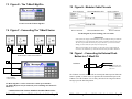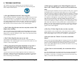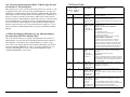
1
_____________________________________________________
T-Max® Manager/Pro and T-Max® 3A User’s Guide Page i
T-Max® Manager/Pro and T-Max® 3A User’s Guide Page ii
1
INSTALLATION ..................................................................2
1.1 CONNECTING THE T-MAX® TIMING SYSTEM ....................2
AUTO ADDRESSING THE 3A TIMERS............................................3
2
6.4 CONNECTING A REMOTE PUSH BUTTON TO THE T-MAX®
3A (OPTIONAL) .........................................................................18
6.5 T-MAX® ENCLOSURE (OPTIONAL) .................................18
INDEPENDENTLY ADDRESSING 3A TIMERS ............4
2.1
SETTING PARAMETERS ON THE T-MAX® 3A .................5
6.6.1 CONNECTING THE ADNET OPTO-ISOLATOR® IN
A T-MAX® SERIES DAISY CHAIN ......................................19
7
7.1
7.2
FIGURE A - FRONT VIEW OF THE T-MAX® 3A ..............20
FIGURE B - REAR VIEW OF T-MAX® 3A CIRCUIT BOARD
20
7.3 FIGURE E - THE T-MAX® MGR/PRO ...............................21
7.4 FIGURE F - CONNECTING THE T-MAX® SERIES..............21
7.5 FIGURE H - MODULAR CABLE PIN-OUTS .........................22
7.6 FIGURE I – CONNECTING AN EXTERNAL PUSH BUTTON TO
A T-MAX® 3A ..........................................................................22
3 SETTING UP THE MANAGER/PRO WITHOUT A
COMPUTER. ...............................................................................7
3.1
3.2
3.2.1
3.2.2
3.2.3
3.3
3.4
3.5
3.6
3.7
4
DESCRIPTION ..................................................................7
INITIAL CONFIGURATION................................................7
Setting up the T-Max® Mgr/Pro. ...........................7
What are Parameters............................................11
Security Levels .....................................................12
STARTING A SESSION ...................................................12
CANCELING A SESSION ................................................13
PAUSING A SESSION .....................................................13
CLEAN ROOM ...............................................................13
CHECKING BED STATUS ...............................................14
IN-ROOM SINGLE BED CONTROL..............................15
4.1
4.2
STARTING A SESSION .......................................................15
PAUSING A SESSION .........................................................15
4.3 CANCELING A SESSION ................................................15
5
REMOTE SINGLE BED CONTROL...............................15
5.1
5.2
5.3
6
WIRING ............................................................................15
CONFIGURATION ..............................................................16
SESSION CONTROL...........................................................16
OTHER FEATURES AND OPTIONS .............................17
6.1
6.2
6.3
6.4
COOL DOWN MODE .........................................................17
T-MAX® MONITOR/PLUS ...............................................17
HIGH PRESSURE (SINGLE-SIDE) BEDS .............................17
Installing External Speaker (Optional) ..........................18
T-Max® Manager/Pro and T-Max® 3A User’s Guide Page iii
FIGURES .............................................................................20
8
TROUBLE SHOOTING.....................................................23
(C) COPYRIGHT 2000 By Salon Systems, Inc
ADI PN: MNTMAXMGRPRO Rev 2
The information in this manual is believed to be correct. However, Salon Systems, Inc. assumes no
responsibility for any errors herein. This information is subject to change without notice, and should
not be construed as a commitment by Salon Systems, Inc.
WARRANTY
This product is warranted against defective materials and workmanship for a period of two years
from date of purchase. In the event the product fails to perform, it may be returned; Shipping Paid, to
the factory to be serviced or replaced at the factory's discretion. Salon Systems, Inc. will pay to ship
the repaired or replaced product by the shipping means of our choosing. Returns will not be accepted
without a Return Authorization Number assigned by the factory.
It is a Condition of Sale that the user of Salon Systems Inc.'s products assumes all risk and
responsibility of use and indemnifies Salon Systems, Inc. against all damages. Salon Systems, Inc. is
not liable for loss of profits, lost savings, special, incidental, consequential, indirect or other similar
damages arising from breach of warranty, breach of contract, negligence, or other legal action even if
Salon System, Inc. or its agent has been advised of the possibility of such damages, or for any claim
brought against you by another party. This warranty allocates risks of product failure between the
Purchaser and Salon Systems, Inc. Salon System, Inc.’s hardware pricing reflects this allocation of
risk and the limitations of liability contained in this warranty
It is a violation of the stated warranty to cut or modify the provided modular cables supplied with the
T-Max® Series Timers. Connecting the T-Max® Series to third party timers not approved by Salon
Systems, Inc. also violates the stated warranty. Contact your dealer or Salon Systems, Inc. if you are
not sure if the timer that you are connecting is an approved timer.
T-Max® Manager/Pro and T-Max® 3A User’s Guide Page iv
1 Installation
1.1 Connecting the T-Max® Timing System
1) Place a T-Max® 3A in each room. Place the T-Max® Mgr/Pro at the
front desk.
2) A 50’ modular RJ-22 cable (phone type cable) is provided with each TCongratulations on your purchase of the T-Max® Series Tanning System. The
T-Max® is designed for complete automation and control of your tanning
equipment. The T-max® Manager can be used as a stand alone unit or can be
controlled by a computer using many third party software packages. Manual
operation is accomplished via front panel controls.
Components:
T-Max® Manager Pro:
1 T-Max® Manager Pro Unit
1 9V @ 800 mA Power Transformer
1 RS-232 Cable Com Port Adapter
1 ADNET 2000™ Utility Software (3.5” diskette)
1 T-Max® Manager User’s Manual
T-Max® 3A/F (Sold separately, one required for each unit in the salon):
1 T-Max® 3A Timer Interface
1 9V @ 200mA Transformer
1 T-Max® 3A User’s Guide
1 Modular cable with RJ-22 connectors on both ends
Contact your dealer if any components are missing.
Specifications:
Power Supply
Current Draw
Dimensions
Communications Mgr-PC
IN: 120 VAC
OUT: 9 DC @ 1Amp
800 mA
12.75”x5.5”x1”
RS-232C, 9600 Baud, 8Bit, 1 Stop Bit, No Parity
T-Max® 3A:
Power Supply
Cover Plate
T-Max 3A PCB
Relay:
IN: 120 VAC
OUT: 9-12V (DC or AC)@800mA
200mA
5.25”x5.25”
2.5”x3.75”x1.5”
220VAC @ 5A; SPST Form A
Display:
T-Max® Manager:
T-Max® 3A:
It is very important you use the cables
provided with your T-Max® timers. Making
your own cables is not recommended.
3) Connect the modular cables to each T-Max® 3A and the T-Max®
Mgr/Pro. It does not matter which port you use, the top or the bottom,
because there is not an in or an out. When finished, each T-Max® 3A
should have a modular cable connected to each port, with the exception of
the last T-Max® 3A in the series.
4) Connect the tanning bed to the “J3 Contact” screw terminals on the back
of the T-Max® 3A.
T-Max® ManagerPro:
Current Draw
Dimensions
Max® 3A. Run one modular cable from the T-Max® Mgr/Pro location to
T-Max® 3A in the nearest tanning room. Run the other modular cables
from room to room in a daisy-chain fashion. (See fig. F, page 20).
64 dual color lights showing bed status
1, 16x2 VFD display shows bed time/status
1, two digit display showing bed time & status
_____________________________________________________
T-Max® Manager/Pro and T-Max® 3A User’s Guide Page 1
IMPORTANT: There may be many wires visible on
the tanning bed. Two of these wires are specifically
used for connecting the bed to an external timer. If
you are not sure which two wires to use, refer to
the tanning bed’s manual or contact the bed’s
manufacturer.
5) Each T-Max® 3A came with a 9-12V power supply. If the power
supply is not already connected, connect a power supply to the “PWR IN 912V” screw terminal on the back of each T-Max® 3A.
6) Plug each of the T-Max® 3A’s power supplies into a standard 110V
power outlet.
T-Max® Manager/Pro and T-Max® 3A User’s Guide Page 2
Auto Addressing the 3A Timers.
As you press the Start/Stop buttons in each room, the Maximum Bed
Number on the T-Max® Mgr/Pro will automatically count up.
Note: Customers should not be in the tanning
beds while auto addressing.
11) When you have finished with addressing the timers, press the Enter
button on the T-Max® Mgr/Pro.
7) Apply power to the T-Max® Mgr/Pro. Wait until the T-Max® Mgr/Pro
12) After a short pause, the T-Max® Manager/Pro will then scan. Lights
is done scanning.
will illuminate for each bed found.
8) Press the Call/Menu button on the T-Max® Mgr/Pro.
Installation is now complete!
9) Enter an 888 for the Security Code.
Each T-Max® 3A will show a 99 on their displays and beep
continuously.
If you have a 3A that is not showing
2 INDEPENDENTLY ADDRESSING
3A TIMERS
99 – check your cable connection.
10) Go to each room in the order you want them numbered (1, 2, 3, 4, 5,
6 etc.) pressing the Start/Stop button in each room until all displays show 0
and the alarms stop. Make sure the timer shows “0” before going to the
next room.
If you want to skip a room, press the
NEXT button on your T-Max® Mgr/Pro, and
you can pass over that room number.
If you are installing a new T-Max®
system and have just completed Section 1
(Installation), the addresses on the T-Max®
3A’s are set. You do not need to
independently set addresses on the T-Max®
3A’s.
1) Unplug the power from the T-Max® Mgr/Pro (skinniest wire).
2) Apply power to the T-Max® 3A. It should show a 9.9 and an alarm
The rooms do not need to be
numbered in the order they are wired.
should sound.
If it just shows a 0, go to Step 4.
3) Press and release the Start/Stop button. The display will flash an 8.8 and
the alarm will stop. Press and release the Up button until the display stops
flashing and shows a 0.
T-Max® Manager/Pro and T-Max® 3A User’s Guide Page 3
T-Max® Manager/Pro and T-Max® 3A User’s Guide Page 4
4) Press and hold the Start/Stop and Up buttons together, simultaneously,
2) Press and hold the Start/Stop and Up buttons simultaneously on the T-
concurrently, and at the same time, on the T-Max® 3A until a”.1” appears
on the display. This should take about 5-6 seconds. Release the buttons.
Max® 3A until a .1 appears on the display. This should take 5-6 seconds.
Release the buttons.
5) Press the Start/Stop button on the display. A flashing number will
appear. This is the address that the timer currently has programmed. (If it
is a new timer, it will probably show a 5.2 all flashing – press the Up Arrow
button counting up 5.3, 5.4, 5.5, then the counter starts over at .0, .1, etc. In
most cases, counting up from 5.2 is easier than counting down.)
6) Press the Up or Down button until the desired address is displayed.
3) Press the Up or Down buttons until the parameter number that you want
is displayed.
4) Press the Start/Stop button to see the current value for that parameter.
The Display will show a number with a period in the lower center of
the display. The numbers will stop flashing and stay illuminated. The
number shown is the current value for that parameter.
If you have less than 100 beds - Make
sure you have a solid period, flashing
number.
Note: When setting the addresses, remember these three rules:
•
•
•
Set each T-Max® 3A to a unique address.
Do not set any T-Max® 3A to address 00.
If the period is flashing, you are over address 100.
7) Once the desired address is displayed, press and release the Start/Stop
button. A solid .1 will be displayed.
8) Press and hold both the Up and Down buttons until a 0 is displayed.
Repeat Steps 2-8 for each T-Max® 3A that you are manually addressing.
2.1 Setting Parameters on the T-Max® 3A
Note: If you are using a T-Max® Mgr/Pro and multiple T-Max® 3As,
remove power from the T-Max® Mgr/Pro then unplug the power to each TMax® 3A. Keep power removed from the T-Max® Mgr/Pro until all
parameter changes are complete. Refer to Table 1, (page 8) for Parameter
Numbers and Descriptions.
For Lamp Hours, Session Counts, etc. the value displayed can be as
high as 9999. To display this value, the T-Max® 3A will flash two
numbers-three times, then two numbers-three times, pause, two
numbers-three times, two numbers-three times, pause, etc. For
example, if you are checking lamp hours (Parameter 6) and the display
flashes the numbers 53 three times, then 14 three times, pauses then
repeats, then the total lamp hours stored in that T-Max® 3A is 5314.
5) Press the Up or Down button to change the parameter to the desired
value.
If you want to clear the value for that parameter, press the Up and
Down buttons at the same time until the display shows “.0”.
6) Press the Start/Stop button.
The display will show the parameter number you just changed and a
solid period in the lower center of the display. You may now change
another parameter by pressing the Up and Down buttons until the
parameter you want displayed. Repeat Steps 2-4.
7) To exit the Parameter mode and make the T-Max® 3A available for the
next session, press and hold both the Up and Down buttons until the display
shows a 0 with no periods.
1) Apply power to the T-Max® 3A.
T-Max® Manager/Pro and T-Max® 3A User’s Guide Page 5
T-Max® Manager/Pro and T-Max® 3A User’s Guide Page 6
3 SETTING UP THE MANAGER/PRO
WITHOUT A COMPUTER.
If you want the session to start right away,
enter a delay of 0. The maximum setting for
delay is 10 minutes. This setting is for
every bed in the salon.
7) The following message will appear: MGR START MODE. Enter the
desired Auto Start Mode followed by the ENTER button.
3.1 Description
The T-Max® Mgr/Pro has 64 dual-colored lights showing bed status.
A 16x2 VFD display on the upper right corner of the T- Max® Mgr/Pro
shows bed status and times. A 16-key keypad allows the user to control the
salon.
3.2 Initial Configuration
3.2.1 Setting up the T-Max® Mgr/Pro.
This setting is for every bed in the salon.
If a 0 is entered, the bed will not come on automatically when the
delay time expires, but session time will begin counting down (the 0
will not appear on the display). The Start button must be pressed in the
room, for the bed to come on.
If a 1 is entered, the bed will come on immediately after the delay time
expires.
If a 2 is entered, then the T-Max® Mgr/Pro is set to infinite delay and
session will not start until the Start/Stop button is pressed on the TMax® 3A.
1) Apply power to the T-Max® Mgr/Pro. The T-Max® Mgr/Pro will scan
the network to find all T-Max® 3As.
2) Press the Call/Menu button. The following message will appear:
SECURITY#.
A sheet was provided showing the factory
default settings for each security level and
security level descriptions. You must go to
security level 3, and enter that security #.
If the T-Max® Mgr/Pro is controlled
by a computer, the Delay and Auto Start
mode are controlled by the computer’s
software - unless you set the Infinite Delay.
If the T-Max® Mgr/Pro is set to Infinite
Delay, the Delay time set in the T-Max®
Mgr/Pro or the PC will be ignored.
3) The following message will appear: GET PARAMS? Press NEXT
4) The following message will appear: SEND PARAMS? Press NEXT
5) The following message will appear: MGR PARAMS? Press ENTER
6) The following message will appear: MGR DELAY TIME. Enter the
8) The following message will appear: MGR MAX BED. Enter the
maximum bed number followed by the ENTER key.
delay time in minutes, followed by the ENTER button.
T-Max® Manager/Pro and T-Max® 3A User’s Guide Page 7
T-Max® Manager/Pro and T-Max® 3A User’s Guide Page 8
This number must be equal to or
higher than the highest address that a TMax® 3A is set. For example if you have six
beds, but are addressing the T-Max® 3As to
1,2,3,4,5, and 8, set the maximum bed
number to 8.
9) The following message will appear: MANAGER NUM. If you are
using one Manager, press ENTER. If you are using multiple Managers,
enter the T-Max® Mgr/Pro address, followed by the ENTER button.
Up to 8 T-Max® Mgr/Pro’s can be connected in a single salon. One TMax® Mgr/Pro must be set to address 0. All slave T-Max® Mgr/Pro’s must
be set to an address other than 0. Set each Slave T-Max® Mgr/Pro to a
unique address.
10) The following message will appear: MGR RE-SCAN TIME. Press
the ENTER key (without entering a number).
Table 1 - Parameter Numbers
Param
#
1
2
3
4
5
6
7
8
9
10*
13
15
11) The following message will appear: MAX SLAVE. If you are only
using one Manager, press ENTER (without entering a number). If you are
using multiple Managers press 7, then ENTER.
The VFD display will then read SAVING PARAMS.
17
18
20
21
22
T-Max® Manager/Pro and T-Max® 3A User’s Guide Page 9
Description
Max #
Default
Notes
Address
Beep Mode
255
1
254
0
Address of T-Max® 3A
Used for High Pressure beds. 0=Alarm only, 1=Alarm
and Flip
Delay in minutes stored in the T-Max® 3A.
For the T-Max® Sentry™ Option. 0=Disabled,
1=Enabled.
Total session counts for T-Max® 3As.
Delay Time
Current
Sense
Session
Counts
Lamp Hours
Bed Hours
Manual
Session
Counts
Clean Room
Manual
Lockout
Cool Down
Mode
Fixed
Session
Counts
Clean Clear
10
1
0
0
65535
0
65535
65535
65535
0
0
0
Bulb hours for each bed.
Number of hours a bed is on.
Counts the number of sessions the T-Max® 3A has
run while in Stand Alone Mode
1
1
1
0
0 = Clean Room Disabled, 1 = Enabled
0 = Stand Alone Enabled, 1 = Disabled
10
0
0 = Disabled, 1-10=Enabled. Time delay in minutes
allowing bed to cool.
65535
0
Counts number of sessions ran through the T-Max®
3A. This value cannot be changed at all. Used as
point of reference.
1
0
0 = Press and hold the Up button for 3-4 seconds to
clear the clean room. 1 = Press and release the Up
button to clear instantly.
Redisplay
2
0
0 = After a session ends and the clean room is
cleared, the T-Max® 3A will show a 0. 1 = After
session ends and the clean room is cleared, the TMax® 3A will show the last session time entered. 210 = After the session ends and the clean room is
cleared, the max. time will show on the T-Max® 3A.
External
1
0
0 = Speaker on T-Max® 3A, 1 = External Speaker
Speaker
will be used.
Pause Mode
1
0
0 = When session is paused, time will continue to
count down. 1 = When session is paused, session time
will stop counting down.
Auto Bed
1
0
For T-Max Intercom Systems Only. 0 = When timer
Shut Off
is called, bed will stay on, 1 = When timer is called,
bed will shut off automatically.
•
If Manual Lockout is enabled, the T-Max® 3A cannot operate as a stand-alone
timer. In the event of a T-Max® Mgr/Pro failure, this parameter cannot be enabled
at the T-Max® 3A
T-Max® Manager/Pro and T-Max® 3A User’s Guide Page 10
3.2.3 Security Levels
3.2.2 What are Parameters
Parameters are values stored in each T-Max® 3As such as Lamp Hours,
Session Counts, etc. Table 1 shows the parameter numbers and details
about them.
To get or change parameters, do the following:
1) Press the BED NUMBER you want to check or change, followed by the
ENTER key. The bed number and its status will appear.
2) Press the CALL/MENU button.
3) The following message will appear: SECURITY#. Enter the security
number for level 3 followed by the ENTER key.
4) The following message will appear: GET PARAMS? Do you want to
see what is stored, or change it?
If you just want to see current values, press ENTER
If you want to send new values, go to Step 6.
5) The following message will appear: WHICH PARAMETER? Enter the
parameter number from Table 1 followed by the ENTER key.
The top line on the VFD display will show the bed number. The
second line will show the value for the parameter you checked.
Press CLEAR to exit.
6) Press the NEXT button.
7) The following message will appear: SEND PARAMS? Press the
ENTER button.
8) The following message will appear: WHICH PARAMETER? Enter the
parameter number from Table 1 followed by the ENTER button.
9) The following message will appear: SEND WHAT DATA? Enter the
value that you want to store in that timer followed by the ENTER button.
Press CLEAR to exit.
There are 5 security levels on the T-Max® Mgr/Pro. When the Menu
button is pressed, the display will prompt you for a security number. Refer
to the enclosed Security Number Sheet on how to change security numbers.
The description of these levels follows:
Level 0 - Computer Control Level
Sessions can be monitored, but not started manually.
Level 1 - Employee Level
Session operation only. No parameters can be observed or changed.
Level 2 - Supervisor Level
Parameters values can be observed but not changed.
Level 3 - Manager Level
Parameters can be observed and changed. Security numbers cannot be
changed.
Level 4 - Owner Level
This level allows the changing of security numbers for access.
Asterisks will be displayed on the lower left corner of the VFD indicating
which security number was last entered, a single asterisk for level 1, 2
asterisks for level 2 and 3 asterisks for level 3.
3.3 Starting A Session
You must be at Security Level 1, 2
or 3 to start sessions manually. If you
don’t have any asterisks in your VF
Display – you can’t send time from the
Manager.
1) Press the BED NUMBER you want to start, followed by the ENTER
button.
2) Press the TIME button. The display will read “Enter Session Time”.
3) Enter the SESSION TIME you want followed by the ENTER button.
T-Max® Manager/Pro and T-Max® 3A User’s Guide Page 11
T-Max® Manager/Pro and T-Max® 3A User’s Guide Page 12
The delay will count down on the display. If an Infinite delay has been
set up, the session time will show but will not count down. DELAY
will show for status. Once the customer presses the Start/Stop button
on the T-Max® 3A in the room, the session will start. The display will
show the session time counting down and the status will stay ON.
3.4 Canceling A Session
3.7 Checking Bed Status
To check the status of a bed, glance at the 64 dual colored lights.
Green = Bed is ready for a new session.
Red = Bed needs to be cleaned.
Off = Bed is not available.
Flashing Red = There are less than two minutes left in a session.
Flashing Green = Bed is in the Cool Down Mode.
Yellow = Scanning or Error.
1) Press the BED NUMBER that you want to cancel, followed by the
ENTER button.
To check time remaining in an active session, press the bed number
followed by Enter.
2) Press the TIME button. The message “Enter the Time” will appear on
To check the times on all beds, press the Next or Prev (previous) button
repeatedly.
the VFD display.
3) Press the ENTER button (without entering any time).
If the clean room is enabled and the delay time has expired, DIRTY
will appear on the display the Status LED will be red. Once the clean
room signal has been cleared, the display on the T-Max® Mgr/Pro will
show READY and the Status LED will turn green.
3.5 Pausing A Session
To pause a session, press the START/STOP button on the T-Max® 3A at
the tanning bed. The flashing period will stop flashing and stay illuminated.
The T-Max® Mgr/Pro display will show PAUSE on the display.
The session will start and the display will show the bedtime and status.
3.8 To add T-Max® Mgr/Pro’s
1) The side of the T-Max® Manager/Pro has 2 terminator switches. Flip
these two switches up to the OFF positions on each slave T-Max®
Mgr/Pro.
2) Apply power to each Slave T-Max® Mgr/Pro.
3) Make sure each Slave T-Max® Mgr/Pro has a unique address.
4) Connect each slave T-Max® Mgr/Pro where you want in the daisy.
Note: The session time will continue to count and the display will reflect
the remaining session time.
5) Apply power to the Master T-Max® Mgr/Pro.
To restart the session, press the START/STOP button on the T-Max® 3A.
The period will continue flashing and the Status on the T-Max® Mgr/Pro
will change to ON.
Max® Mgr/Pro.
3.6 Clean Room
Once the session time is over, the display will show two periods with no
numbers, which is an indication that the room needs to be cleaned. To clear
the clean room signal, press and hold the Up Arrow button on the T-max 3A until the timer beeps and shows 0.
T-Max® Manager/Pro and T-Max® 3A User’s Guide Page 13
6) Refer to Section 3.2.1.9 and Set the Max. Slave Setting on the Master T7) Cycle power to the Master T-Max® Mgr.
Each Slave T-Max® Mgr/Pro must be powered up
before you power the Master T-Max® Mgr/Pro. Each Mgr/Pro
can be used to cancel a session, start a session, and monitor all
sessions. However, parameters (bulb hours, session counts, etc.)
can only be monitored and changed from the Master T-Max®
Mgr/Pro.
T-Max® Manager/Pro and T-Max® 3A User’s Guide Page 14
4 IN-ROOM SINGLE BED CONTROL
4.1 Starting a Session
If you are using a T-Max® Mgr/Pro and you want to use the T-Max® 3As
manually, you must unplug power from the T-Max® Mgr/Pro, unplug
power from all the T-Max® 3A’s, then plug the timers back in. Power must
stay removed from the T-Max® Mgr/Pro while the T-Max® 3A is being
used independently.
1) Press the Up and Down button on the T-Max® 3A until the session time
is displayed. If the display shows a 0, and you want to count down from the
maximum time, press the Down button.
described in Section 1.1. Run the provided modular cable from the tanning
room to the remote T-Max® 3A. Connect the modular cable to one of the
RJ-22 ports on each T-Max® 3A (it does not matter which one.)
5.2 Configuration
Set the address on the T-Max® 3A in the tanning room to “1”, and the
address on the T-Max® 3A at the front desk to “0” as described in Section
2.0. Disconnect the modular cables when setting the addresses on both TMax® 3As.
Use the Front Desk T-Max® 3A to set the Delay. Any delay time set on the
T-Max® 3A in the tanning room will be ignored.
2) Press and release the Start/Stop button to start the session.
If a delay other than 0 is programmed, the delay time will begin
counting down. A period on the lower right corner of the display will
flash rapidly. When the session starts, the period will flash at a once
per second rate.
4.2 Pausing a Session
To pause a session, press the Start/Stop button. The flashing period on the
lower right corner of the display will stop flashing. The session time will
continue to count down.
To restart the session, press the Start/Stop button on the T-Max® 3A. The
period on the lower right corner of the display will resume flashing.
4.3 Canceling a Session
To cancel a session, press the Start/Stop button to pause the session then
press the Up button. The display will show a solitary 0.
5 REMOTE SINGLE BED CONTROL
A T-Max® 3A can be used to control another T-Max® 3A. This is ideal for
small salons that are not using a T-Max® Mgr/Pro. Two T-Max® 3As are
required for remote single bed control.
5.1 Wiring
Place one T-Max® 3A in the tanning room and one at the desired remote
location. Connect the 9V @ 200mA power supply to the “power in” on the
back of each T-Max® 3A. Plug each power supply into a 120VAC outlet.
Connect the T-Max® 3A in the tanning room to the tanning bed as
T-Max® Manager/Pro and T-Max® 3A User’s Guide Page 15
Note: The max. time is controlled by the T-Max®
3A in the tanning room and not by the T-Max® 3A at the
front desk.
5.3 Session Control
5.3.1 Starting a Session
1) Press the Up or Down button on the T-Max® 3A at the front desk until
the session time is displayed.
2) Press the Start/Stop button on the front desk T-Max® 3A to start the
session.
If a delay other than 0 is set, the delay will count down. A period on
the lower right corner of the display will flash rapidly. When the
session starts, the period will flash at once per second rate. If there is
no delay entered, the session will start immediately.
5.3.2 Pausing During the Session
To pause the session, press the Start/Stop button on the T-Max® 3A in the
tanning room. The flashing period on the lower right corner of the display
will stop flashing and stay illuminated. The session time will continue to
count down and reflect the remaining session time. To restart the session,
press the Start/Stop button on the T-Max® 3A in the tanning room. The
period will continue flashing.
5.3.3 Canceling a Session
Press the Start/Stop and Up buttons on the T-Max® 3A at the front desk at
the same time.
T-Max® Manager/Pro and T-Max® 3A User’s Guide Page 16
6 OTHER FEATURES and OPTIONS
6.1 Cool Down Mode
Cool Down mode is used for beds that require a time to cool down before
the next session can be run. High-pressure beds primarily require this.
While the T-Max® 3A is in Cool Down Mode, a session cannot be started
until the cool down time has expired.
To enable Cool Down Mode, set parameter 13 to the time in minutes you
want the cool down time to last. Setting parameter 13 to 0 disables Cool
Down Mode.
After the session ends, the T-Max® 3A will go into Cool Down Mode. A
single period will be displayed on the T-Max® 3A and T-Max® Mgr/Pro
will show a flashing green light for the duration of the cool down time. The
T-Max® Mgr/Pro display will show “Cool”, with the time counting down.
If “Clean Room” is also enabled, the clean room will be displayed. The TMax® Mgr/Pro display will show “Dirty” and the light for that room will
be solid red, but the Cool Down time will be shown counting down. If the
room is cleaned before the cool down time has elapsed or if the “Clean
Room” is disabled, a solid period will be displayed on the lower center on
the T-Max® 3A. You cannot start a session until the cool down time has
elapsed.
6.2 T-Max® Monitor/Plus
The T-Max® Monitor/Plus allows the salon owner to check the status of all
the beds at any place in the salon.
The T-Max® Monitor/Plus has 16 LED displays showing remaining
session time. Multiple T-Max® Monitor/Plus’ can be connected for large
salons. The T-Max® Monitor/Plus can be connected anywhere in the TMax® chain. You can connect them at the front desk if you want to glance
over and see remaining session time, or you can place them anywhere else
in the salon so the cleaning staff can see how much session time is
remaining for each room. Contact your dealer for more information.
6.3 High Pressure (Single-Side) Beds
The T-Max® 3A has an alarm that will beep for 10 seconds half way
through the session informing the customer to turn over. If you are not
using a T-Max® Mgr/Pro, this option must be enabled at the factory.
6.4 Installing External Speaker (Optional)
If the speaker on the T-Max® 3A is not loud enough, a T-Max® Speaker
that connects to the T-Max® 3A is available. To install the T-Max®
Speaker, do the following: (see Figure B Section 7.2 for J6 location and J99
and J100 locations and jumper positions).
1) Connect the cable on the T-Max® Speaker to the J6 on the back of the
T-Max® 3A.
2) Place the Jumper on J100 to pins 2 and 3 on the back of the T-Max®
3A.
3) Set Parameter 20 to a 1.
6.4 Connecting a Remote Push Button to the TMax® 3A (Optional)
A T-Max® 3A can be used to control another T-Max® 3A. This is ideal
for small salons who are not using a T-Max® Manager. Two T-Max® 3As
are required for remote single bed control.
A remote push button can be connected to the T-Max® 3A to start sessions.
You can get an external start kit from your distributor that provides a 50’
cable with a push button and a wall mounting plate.
Connect the wires from your external push button circuit to the “EXT
START” screw terminals on the back of the T-Max® 3A. Place a jumper
on J100-pins 2 & 3 (See Figure B, Section 7.2 for jumper locations. See
Figure I on page 21 for an example of an External Push Button circuit).
When the external push button is pressed a contact closure is applied to the
Ext. Start screw terminals on the back of T-Max® 3A.
To start a session, press the Up or Down button on the T-Max® 3A to set
the time, then when ready, press the remote push button instead of the
Start/Stop button on the T-Max® 3A.
6.5 T-Max® Enclosure (Optional)
The T-Max® Enclosure allows the T-Max® to either be hung on a wall or
set on a table. Tear drop holes on the back of the T-Max® Enclosure allow
for easy installation.
The T-Max® Enclosure is slanted to make the T-Max® 3A push buttons
and display easy to access and read. The T-Max® 3A can fit so that it is
slanted up or down. Slanted up is ideal for setting the timer on a desk.
Slanted down is great for hanging the T-Max® 3A on a wall.
To install the T-Max® 3A to the T-Max® Enclosure, first run the cable
through the wire holes on the T-Max® Enclosure and connect them to the
T-Max® Manager/Pro and T-Max® 3A User’s Guide Page 17
T-Max® Manager/Pro and T-Max® 3A User’s Guide Page 18
T-Max® 3A. Connect the grommets to hold the wires in tight. Plug any
unused holes with the provided plastic plugs. Connect the T-Max® 3A to
the T-Max® Enclosure using the four screws provided with the T-Max®
3A.
6.6 ADNET Opto-Isolator (Optional)
7 FIGURES
7.1 Figure A - Front View Of The T-Max® 3A
The ADNET Opto-Isolator® is a device that isolates both sides of the
communications between the T-Max® Manager and the rest of the salon. By
converting the data signal from the T-Max® Manager to light, then back to hard
wire, the two sides of the communications connected to the Opto-Isolator are
physically disconnected, yet communication passes through. This helps prevent
damage due to power surges, and remedies problems caused by ground isolation
problems found in some buildings.
6.6.1 Connecting the Adnet Opto-Isolator® in a T-Max® Series Daisy
Chain
T-Max® 3A
1. Disconnect the modular cable from the T-Max® Manager.
2. Connect the cable that was disconnected from the T-Max® Manager (the
cable connected to the first timer in the daisy-chain) to the Output RJ-22
modular port on the ADNET Opto-Isolator®.
3. Connect one end of the modular cable that was provided with the ADNET
Opto-Isolator® to Input RJ-22 connector on the ADNET Opto-Isolator®.
7.2 Figure B - Rear View Of T-Max® 3A Circuit
Board
Pwr 9-12V
4. Connect the other end of the modular cable that was provided with the
ADNET Opto-Isolator® to the T-Max® Manager.
5. Apply Power to the ADNET Opto-Isolator® by connecting both provided
power supplies to the 9-12V AC power input terminals and then plugging the
power supplies into a standard 110VAC outlet.
JP1
Pin 1
J100 Jumper Settings
Ext. Start Switch: 2&3 ON
IC16C73A
Relay
RJ-22 Cables
J99 Settings
Sentry: 1-2 ON
TPI: 2&3 ON
J6
Input
T-Max® Manager
9-12V AC/DC
Contact
Output
T-Max® 3A Connections
9-12V AC/DC
T-Max® 3A
1
2
3
Jumper On Pins 1 and 2
120V AC
ADNET Opto-Isolator®
120V AC
T-Max® Manager/Pro and T-Max® 3A User’s Guide Page 19
1
2
3
Jumper on Pins 2 and 3
1
2
3
Jumper Off
Jumper Positions for J99 and J100
T-Max® Manager/Pro and T-Max® 3A User’s Guide Page 20
7.3 Figure E - The T-Max® Mgr/Pro
7.5 Figure H - Modular Cable Pin-outs
RJ-22 Connector
Untwisted Modular Cable
RJ-22 Connector
Front View of the T-Max® Mgr/Pro
7.4 Figure F - Connecting The T-Max® Series
RJ-22 Connector
Untwisted Modular Cable
RJ-22 Connector
Use this diagram if you are making your own cables
Important!!!
Salon Systems, Inc. highly recommends that you do not modify the cables provided with
each T-Max® 3A. If you need longer cables, contact your dealer or Salon Systems, Inc.
All cables are pre-tested at the factory for proper connection. If you are not careful in
making your own cables, the system may not work properly!
Note: If you are making your own cables, you will need a tool for connecting RJ-22
connectors. Call Techni-Tool @ 1-800-832-4866 and ask for part number 702ST019.
9VAC
RJ-22 Modular Cables Link Each Room.
7.6 Figure I – Connecting An External Push
Button to a T-Max® 3A
Pushbutton
DB9F RS-232 Connector
RJ-22 Modular
Cable Connector
To external start screw
terminals on back of TMax® 3A
The T-Max® 3A can be ordered with an external push button option. When the
button is pushed, a contact closure is applied to the External Start input on the
T-Max® 3A. If the T-Max® 3A is in delay, the bed will be energized without
having to press the Start/Stop button.
2 T-Max® Mgr/Pro’s can be connected to control up to 128 beds!
An ADNET-Repeater may be needed if you are installing more than 25 TMax® 3A’s.
CONNECTING THE T-Max® SERIES IS EASIER THAN EVER!
T-Max® Manager/Pro and T-Max® 3A User’s Guide Page 21
T-Max® Manager/Pro and T-Max® 3A User’s Guide Page 22
8 TROUBLE SHOOTING
The T-Max® Series has been designed for years of trouble free service.
However, if a problem does arise, please follow these trouble shooting steps
before calling technical support.
1) No Lights Illuminated on the T-Max® Mgr/Pro.
Make sure that the transformer is plugged into the wall and into the power input
on the T-Max® Mgr/Pro. Try plugging the T-Max® Mgr/Pro into a different
outlet. If you are using a surge suppresser or UPS backup system, try plugging
the T-Max® Mgr/Pro directly into the wall outlet. Check the circuit breaker in
your building to make sure it is on. Use a voltmeter to measure the voltage on
the transformer on the end which connects to the T-Max® Mgr/Pro.
2) The T-Max® Mgr/Pro does not show any beds, and the VFD
display shows nothing.
This is an indication the program loaded in the T-Max® Mgr/Pro is lost or has
been corrupted. Download programming from the Adnet 2000 to the T-Max®
Manager Pro or return the manager for repair. Refer to the Adnet 2000 manual
for downloading instructions.
3) The T-Max® Mgr/Pro does not see any beds.
Go through the Quick Installation setup in Section 2. Cycle power on the TMax® Mgr/Pro. The T-Max® Mgr/Pro will rescan the network. Make sure each
T-Max® 3A has a unique address.
4) When going through the Quick Installation set-up, when I
5) When power is applied to the T-Max® Mgr/Pro, beds 1-5
show on the T-Max® Mgr/Pro, but the rest of my beds do not
show.
Go through the Quick Installation in Section 2. Make sure that power is applied
and modular cables are connected to each T-Max® 3A. Try a new modular
cable between the last T-Max® 3A displayed and the first T-Max® 3A that does
not show on the T-Max® Mgr/Pro in the daisy chain. If you do not have a spare
cable, swap the suspected defective cable with a cable between two T-Max®
3A’s that show on the Mgr/Pro. If the problem follows, the modular cable is
either bad or wired incorrectly. Check the modular cable pin-outs on the
defective cable (refer to Section 12.9, Figure I). If the problem does not follow,
swap the first T-Max® 3A that does not appear on the T-Max® Mgr/Pro in the
daisy chain with one that does. If the problem follows, return the defective TMax® 3A for repair. If the problem does not follow, swap the last T-Max® 3A
that appears on the T-Max® Mgr/Pro with one of the other T-Max® 3As that
appears on the T-Max® Mgr/Pro.
6) The Slave T-Max® Mgr/Pro does not show any beds.
Check and make sure the modular cable is connected to the Slave T-Max®
Mgr/Pro. Recycle power to the Master T-Max® Mgr/Pro. Cycle power to the
Slave T-Max® Mgr/Pro then cycle power to the Master T-Max® Mgr/Pro.
8) How do I make the T-Max® 3As work as stand-alone
timers?
Remove power from the T-Max® Mgr/Pro. Unplug power from each T-Max®
3A, wait 5 seconds, then plug them back in. On the T-Max® 3A, press the Set
button to set time, and then press the Start/Stop button to start the session.
Power to the T-Max® Mgr/Pro must stay off while the T-Max® 3As are being
used as independent timers.
press 888 then Enter on the T-Max® Mgr/Pro to set the
addresses, some or all of the T-Max® 3As do not go to 99 and
buzz.
9) When I start a session manually, the session time will not
Check the cable between the T-Max® Mgr/Pro and the first T-Max® 3A or
between the T-Max® 3A that is buzzing and the next T-Max® 3A on the daisy
chain that is not buzzing. Replace communication chips in the T-Max® 3A’s
that are not showing a 99 and buzzing.
Press the Call/Menu button. The following message will appear: SECURITY #.
Enter your security number for Security Level 1 (See the enclosed Security
Level Sheet). An Asterisk (*) will appear on the lower left corner of the VFD
display. You can then start sessions manually.
T-Max® Manager/Pro and T-Max® 3A User’s Guide Page 23
T-Max® Manager/Pro and T-Max® 3A User’s Guide Page 24
start.
10) I can start sessions from the Master T-Max® Mgr/Pro, but
not the Slave T-Max® Mgr/Pro.
Enter Security Level 1 (See your enclosed Security Sheet). An Asterisk (*) will
be displayed on the lower left corner of the T-Max® Mgr/Pro. Cycle power to
both the Slave T-Max® Mgr/Pro then the Master T-Max® Mgr/Pro. Watch the
VFD display. On the lower right, make sure the display shows “VER-202/T”. If
it does not, contact your dealer for the latest T-Max® Series Utility Software
and load it into the T-Max® Mgr/Pro as described in Section 6. Check and make
sure the modular cable is connected to the Slave T-Max® Mgr/Pro. Recycle
power to the Master T-Max® Mgr/Pro. Go into the Master T-Max® Mgr/Pro
parameter mode (Security Level 3) and set the Max Slave Number to 7. Cycle
power to the Slave T-Max® Mgr/Pro then cycle power to the Master T-Max®
Mgr/Pro.
8.1 Error Codes
Error
T-Max®
3A
Codes
T-Max®
Mgr/Pro
Description
Possible Solution
Unrecognized
Parameter
EEPROM
Error - On
power up, detects
error.
Current Sense
Error - Current
Off
Session has
started but bed is
off.
Load the T-Max® Manager/Pro with the newest
version of software.
1) Cycle power on T-Max® Mgr/Pro
2) Check parameters on T-Max® 3A.
3) If error occurs repeatedly, return T-Max® 3A for
service.
1) If you are not using a T-Max® Sentry, set
parameter 4 to 0.
Check to see if bed is off or illuminates
momentarily.
If bed is off
1) Check power to bed.
2) Check outlet bed is plugged into.
3) Check circuit breaker
4) Swap T-Max® 3A with one that is working.
If bed illuminates momentarily:
1) Make sure T-Max® Sentry™ is connected
properly (refer to T-Max® 3A User’s Guide).
2) Have electrician check beds current draw. If the
bed draws less than 10AMPS, wire from the bed
needs to be wrapped around the T-Max® Sentry™
one time. Refer to T-Max® 3A User’s Guide.
Check to see if bed is on or off. If bed is on:
1) Swap T-Max® 3A with one that is working
properly.
2) Check bed for proper operation.
If bed is off
1) Have electrician check the current draw on bed. If
fans drawing <5AMPS, wrap wire from bed around
the T-Max® Sentry™ one time. Refer to T-Max®
3A User’s Guide.
1) Check the delay on the T-Max® 3A. Make sure
the Delay is not set to 55.
2) Replace the T-Max® 3A.
N/A
E0
91
E1
92
E2
93
E3
Current Sense
Error - Current
On
Session has
expired but bed
remains on.
94
E4
N/A
E6
N/A
E7
Max Time
Error - T-Max®
3A reporting
wrong Max time.
Checksum
Error - T-Max®
Mgr/Pro received
bad value from
T-Max® 3A
Time Out Error
- The T-Max®
Mgr/Pro did not
receive the
correct
information from
the T-Max® 3A
11) When checking my bulb hours (or any other parameter),
the value shows 65535 for all beds. Why?
This is an indication that you are trying to check parameters from a Slave TMax® Mgr/Pro. You can only check and change parameters from a Master TMax® Mgr/Pro. To determine if the T-Max® Mgr/Pro is a master or slave,
cycle power to the T-Max® Mgr/Pro and watch the VFD display. The top line
will read “TESTING MEMORY #”. If the # is a number other than a 0 (1-7),
then this T-Max® Mgr/Pro is a slave. The T-Max® Mgr/Pro that reads
“TESTING MEMORY 0” is the master.
T-Max® Manager/Pro and T-Max® 3A User’s Guide Page 25
1) Cycle power on the T-Max® Mgr/Pro and TMax® 3A.
2) Swap the T-Max® 3A with one that is operating
correctly.
1) Make sure 9VAC @ 200mA transformer
powering T-Max® 3A is plugged in to 120VAC
outlet.
2) Swap transformer with one that is working.
3) Check modular cable to make sure it has not been
disconnected. Replace modular cable.
4) Swap T-Max® 3A with one that is working.
T-Max® Manager/Pro and T-Max® 3A User’s Guide Page 26
ADNET-Repeater™, 21
Auto Addressing
See Quick Installation.
Auto Start
Manual Setup, 7
Bed Status, 13
Cable Pinouts
See Modular Cable Pinouts.
Canceling Sessions
Manually, 12
Using the T-Max 3A® as an
Independent timer, 14
Cool Down Mode, 16
Delay
Manual Setup, 6
External Push Button
Option, 17, 22
Installation
Quick Installation, 1
Maximum Bed Number
Manual Setup, 7
Modular Cable Pinouts, 22
Parameters
Changing and Getting
Manually, 10
Table, 9
Pausing a Session, 12, 14
Quick Installation, 1
Security Numbers, 11
Starting Sessions
Manually, 11
T-Max® 3A
Canceling Session, 14
Circuit Board Connections,
20
Diagram, 19
External Push Button, 17, 22
Pausing Session, 14
Setting Parameters Manually,
4
Setting the Address Manually,
3
Using as an Independent
timer, 14
T-Max® Enclosure, 18
T-Max® Manager/Pro
Address, 8
Going From Computer to
Manual Control, 11
Manual Set Up, 6
Starting Sessions Manually,
11
T-Max® Monitor/Plus, 16
T-Max® Speaker, 17
T-Max®3A
Enclosure, 18
RemoteSingleBedControl, 14
Trouble-Shooting, 23
Wiring, 1, 21
T-Max® Manager/Pro and T-Max® 3A User’s Guide Page i