1
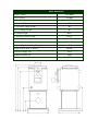
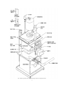
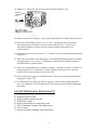
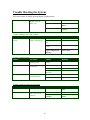
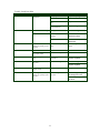
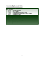
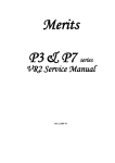
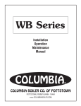
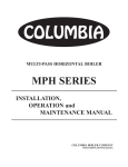
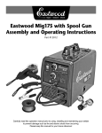
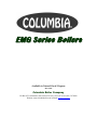
EMG Series Boilers
Available in Natural Gas & Propane
Rev 12012
Columbia Boiler Company
PO Box 1070 • Pottstown, PA 19464 • Tel (610) 473-8457 • Fax (610) 367-6800
Website www.columbiaboiler.com • Email [email protected]
Safety Instructions - Read Before Installing & Operating Equipment
W
Waarrnniinngg::
If you do not follow these instructions exactly, a fire or explosion
may result causing property damage, personal injury or loss of life
A) This appliance does not have a pilot. It is equipped with an ignition device which automatically
lights the burner. Do not try to light the burner by hand.
B) Before operating equipment smell around the appliance area for gas. Be sure to smell next to the
floor because some gas (specifically L.P.) is heavier than air and will settle to the floor.
C) If you smell gas:
1) Do not try to light any appliance
2) Do not touch any electric switch
3) Do not use any phone in the building
4) Contact your gas supplier immediately using a neighbor’s phone
5) Follow the gas supplier’s instructions
D) Use only your hand to push in or turn the gas control knob. Never use tools. If the knob will not
push in or turn by hand, don’t try to repair it, call a qualified service technician. Force or attempted
repair may result in afire or explosion.
E) Do not use appliance if any part has been under water. Immediately call a qualified service
technician to inspect the appliance and to replace any part of the control system and any gas control
which has been under water.
Operating Instructions – Quick Reference
1) Read all instructions prior to operating equipment.
2) Set the thermostat to the lowest setting.
3) Turnoff all electric power to the appliance.
4) This device is equipped with an ignition device which
automatically lights the burner. Do not try to light the
burner by hand.
5) If the gas control knob is not in the “OFF” position, turn knob clockwise to the “OFF” position.
6) Wait five (5) minutes to clear out any gas. Then smell for gas, including near the floor. If you
smell gas, stop immediately.
7) Turn gas control knob counter-clockwise to “ON”.
8) Turn on all electric power to the appliance.
9) Set the thermostat to the desired setting.
10) If the appliance does not operate, follow the instructions.
Turning Gas Off To Appliance – Quick Reference
1) Set the thermostat to lowest setting.
2) Turn off electric power to the appliance if service is to be performed.
3) To turn off gas to the appliance, turn the gas control knob clockwise to “OFF”.
Contents
Safety Instructions
i
Product Features
1
Installation
3
Start Up
6
Maintenance
8
Trouble Shooting
9
Parts
12
Over fifty years of engineering and product development have gone into your new
Columbia boiler. Its quality and design are unsurpassed. Properly installed and
maintained, it will provide many years of efficient and dependable operation. Please
read this instruction manual carefully. The information contained within is designed
to help you maintain peak performance from your unit.
Product Features
•
•
•
•
•
•
•
ASME Coded Boiler Registered with National Board
Factory Mounted / Wired Burner and Controls
Fully Insulated Heat Exchanger with Powder-Coated Cabinet
Packaged with Standard Five Gallon per Minute Tankless Coil (Domestic Hot Water)
Equipped with Triple Aquastat, Circulator, Temperature / Altitude Gauge and Gas Regulator
Outfitted with Additional Orifices to Achieve a Variety of Heat Inputs
Provided with a Lifetime Limited Warranty
•
EMG-31 120
EMG-31 140
EMG-31 160
Input (Btu/Hr)*
120,000
140,000
160,000
IBR Heat Capacity (Btu/Hr)
88,000
101,000
114,000
Valve Capacity (Lbs/Hr)
160
160
160
Max Water Pressure (Psi)
30
30
30
Burner Model
Carlin EZ-Gas
Carlin EZ-Gas
Carlin EZ-Gas
Fuel Type
Nat.
Gas
L.P.
Gas
Nat.
Gas
L.P.
Gas
Nat.
Gas
L.P.
Gas
0.242”
11/64
0.250”
13/64
0.290”
7/32
Fuel Input Rate (Cfm)
1.95
0.79
2.28
0.95
2.60
1.06
Max. Inlet Pressure (“W.C.)
11”
11”
11”
11”
11”
11”
Min. Inlet Pressure (“W.C.)
5”
5”
5”
5”
5”
5”
Manifold Pressure (“W.C.)
3.5”
3.5”
3.5”
3.5”
3.5”
3.5”
Factory
Set
Factory
Set
Factory
Set
Factory
Set
Factory
Set
Factory
Set
31%
30%
45%
42%
65%
78%
Draft Over Fire (“W.C.)
-0.02”
-0.02”
-0.010”
-0.02”
-0.005”
-0.005”
Draft in Stack (“W.C.)
-0.02”
-0.02”
-0.02”
-0.015”
-0.02”
-0.02”
CO2 Reading
9.0%
11.0%
9.0%
11.0%
9.0%
11.0%
AFUE
83.8%
83.8%
83.0%
83.0%
82.2%
82.2%
Orifice Size
Head Position
Air Shutter
Boiler Dimensions
Water Content
21 Gallon
Coil Capacity
5 GPM
A) Jacket Height
45”
B) Jacket Width
21”
C) Hydronic Supply Height
43”
D) Coil Supply Height
41”
E) Burner Height
8-1/2”
F) Hydronic Return Height
21-1/2”
G) Flue Pipe Diameter
H) Washout
I) Jacket Depth (Including Flange)
6”
21-1/2”
21”
Depth Front to Rear w/ Burner
29-3/4”
Hydronic Supply Size
1-1/4”
Hydronic Return Size
1-1/4”
Washout Size
3/4”
Installation Procedure
W
Waarrnniinngg::
Unit installation must be performed only by a qualified serviceman
that is familiar with state and local codes.
1) Inspect the boiler package to ensure that no damage occurred during shipment.
Please contact the distributor immediately if there is any sign of damage.
2) Maintain the boiler package in its protective crate as long as possible to prevent any
damage when positioning the boiler. When the boiler package is located adjacent to
its final position, the protective crate may be removed by first cutting the banding
(Note: bands are under tension and will spring back when cut) and then by prying the
individual crate panels. In addition, remove the lag bolts which hold the boiler onto
the skid.
3) Place the boiler on a level floor as near to the chimney as possible. Adhere to the
following minimum clearances to combustible material:
a.
b.
c.
d.
e.
f.
Floor – Non Combustible Floor Only
Sides – 6”
Rear – 6”
Front – 24”
Top – 38”
Chimney Connector (Vent Pipe) – 18”
For clearances less than the listed values, please consult National Fire Protection
Agency (NFPA) -54 National Fuel Gas Code Table 6.2.3(B).
4) Ensure that there is adequate combustion air for the burner. Lack of adequate
combustion air may result in noisy combustion, erratic burner operation, and/or
nuisance lock outs. In addition, the lack of combustion air will result in a shift of the
burner’s performance curve and may result in the generation of CO gases inside of
the heat exchanger. Please refer to the Start Up Procedure & Annual Maintenance
Requirement sections for instructions on setting up and servicing the burner.
For installations in utility rooms or closets, it is necessary to provide two separate
ventilation openings in the door (one located at 12” and the other 60”). Each opening
shall be 160 square inches in size. For installations in buildings with tight
construction (little fresh air infiltration), it is necessary to place an opening in the
exterior wall that is 160 square inches in size and is located adjacent to the boiler.
5) Install piping for the hydronic and domestic hot water systems. Utilize the 1-1/4”
coupling located on top of the boiler for the hydronic system supply and the 1-1/4”
nipple at the midpoint of the front face for the hydronic system return. Connect the
hot water system to the 1/2” copper fittings located on the coil plate. The right side
adapter is for incoming cold water and the left side for outgoing hot water. Pipe the
hydronic and hot water systems as detailed in the following figure. Ensure that all
fittings are tight before filling the system.
6
Note: Installer responsible for ensuring that piping conforms to all applicable codes
7
6) Wire 120 VAC to the aquastat control. Ensure that the hot wire (black) is connected to the
L1 connector, the neutral wire (white) to the L2 connector and the grounding wire (bare) to
the green screw in the control panel. The burner, circulator and control are installed at the
factory and do not require any additional wiring. In addition, it is recommended that a
service disconnect be installed in line with the boiler so that the system may be de-energized
for maintenance and emergencies. All wiring performed at the installation must comply with
local code and NFPA -70 National Electric Code. See burner manual and control manual for
wiring instructions.
7) Follow burner manufacturers instructions for preparation, installation, mounting and
operation of the burner.
8) Connect the flue from the boiler to a 6” listed venting system. For chimney vent systems the
maximum horizontal length must not exceed 10’. Listed draft boosters and regulators may be
used to increase or decrease the draft respectively. The chimney flue must extend 3’ above
the highest point of the roof line and 2’ above the highest structure located in a 10’ radius
Start Up Procedure
9) Make sure service switch to boiler is off.
10) Make sure boiler has been filled with water until entire system has been purged of air
(System pressure must not exceed 30 PSI).
11) Check burner and install desired orifice. See burner manual for instructions. All units are
shipped from the factory with an orifice for each firing rate and natural gas or LP gas. Select
the correct orifice for you application from the chart in this manual and install per burner
instruction manual.
12) Make sure all manual shut off valves in the gas line are open.
13) Bleed off any air in the gas line by attaching a 1/8” NPT nipple and stop cock to the inlet side
of the gas valve. Once a faint smell of gas is noticeable at the fitting, immediately shut off
the stop cock. Allow the gas to dissipate for a period of five minutes prior to proceeding to
the next step.
14) Set the low and high limit of the aquastat operating control to 160oF and 180oF, respectively.
15) Apply power to the system by turning the service switch on.
16) Review the burner manual for additional start-up and operating instructions.
Burner Adjustment
See burner manual for complete adjustment and operating instructions.
Note: The combustion chamber takes approximately 2 hours to cure after starting burner
operation. During that time elevated CO levels will occur until the chamber is cured.
17) For chimney vent applications drill out a small sampling port in the stack (locate
approximately 6” away from the boiler).
8
18) Attach a 1/8” NPT nipple and stop cock to the outlet side of the gas valve.
Regulator
Adjustment
Screw
19) Attach a manometer to the nipple / stop cock assembly and take a reading of the gas pressure.
20) Make sure the manifold pressure is set at 3.5” W.C. Adjustments can be made to the
manifold pressure by turning the set screw located on the gas valve. Gas pressure is
increased by turning the set screw clockwise and decreased by turning the screw
counterclockwise.
21) Allow the boiler to fire for a period of 10 – 15 minutes in order to reach the desired operating
temperature.
22) Take a flue measurement at the sampling port. Draft should be slightly negative for chimney
vent applications (-0.01” to -0.04”). Adjustments to the draft can be made by installing a
listed draft inducer or draft regulator.
23) Take a CO2 measurement using a combustion analyzer. Adjust the air shutter so that the CO2
reading measures 9.0%. Increase the air shutter opening to decrease the CO2 value and
decrease the air shutter opening to increase the value.
24) Use the combustion analyzer to verify that the CO level is below 100 ppm and that the flue
temperature is above 375oF.
25) Cover the drilled out sample port either by applying a silicon sealant or high temperature
tape. It is important to cover the sample port to prevent flue gases from infiltrating through
the opening.
Annual Maintenance Requirements
1)
2)
3)
4)
Inspect gas line for leaks.
Inspect exhaust venting for leaks.
Clean blower wheel.
Inspect electrode tips for unnecessary wear.
5) Take an ohmmeter reading of the flame sensor.
6) Clean air intake.
7) Inspect coil gasket (retighten bolts if necessary).
9
Trouble Shooting the System
See burner manual for trouble shooting burner related problems.
Draft
Take a draft reading; draft
should be -0.02” for
chimney vent
Down drafts
Install a listed vent cap
Insufficient draft
Install a listed draft
inducer
Excessive draft
Install a listed draft
regulator
Trouble: Boiling Noise in Top of Boiler
Source
Procedure
Causes
Remedy
Air Trapped in Boiler /
System
Check if boiler / system is
properly vented (purged)
Defective float vent
Replace vent
Waterlogged expansion
tank
Drain tank
Manual air vent requires
venting
Open air vent
Improper piping (air
trapped at highest point
of piping)
Install air vent at highest
point of piping
Trouble: Too Much Heat
Source
Procedure
Causes
Remedy
Circulator
Check to see if Aquastat is
operating properly
Circulator does not stop
running
Repair
Thermostat
Check thermostat settings
and calibration
Thermostat set too high
Reset thermostat
Thermostat defective
Replace thermostat
Thermostat out of
calibration
Recalibrate thermostat
Flow valve dirty & stuck
Clean flow valve
Flow valve defective
Replace flow valve
Flow Valve
Check to see if flow valve
is operating properly
Trouble: Insufficient Domestic Hot Water
Source
Procedure
Causes
Remedy
Operating Control
Check operating control
Setting too low
Set operating control to
180oF
Coil Heat Exchanger
Inspect coils for fouled
surfaces and / or flow
restrictions
Flow restriction
Remove restriction
Fouled surfaces on heat
exchanger
Clean heat exchanger
surface
10
Trouble: Insufficient Heat
Source
Procedure
Causes
Remedy
Circulator
Check if circulator is
operational
Coupling worn or broken
Replace coupling
Pump binding
Replace pump
Circulator motor burned
out
Replace circulator motor
Wiring from operating
control defective
Repair wiring
Check thermostat settings
Settings too low
Increase setting
Check thermostat location
Bad location due to heat
buildup
Move thermostat to an
alternate location
Out of calibration
Recalibrate or replace
thermostat
Thermostat
Flow Valve
Check flow valve for
sticking in partially closed
position
Flow valve not opening
fully
Clean or replace flow
valve
Radiation
Check radiators for air
Check to ensure radiators
are properly sized
Radiators air bound
Radiators inadequate
Bleed radiators
Install alternate radiators
Boiler
Determine required heat
load
Boiler too small for
application
Additional heating
capacity required
Tankless Coil
Check usage of domestic
hot water
Demand too large
Install flow regulator
Piping
Check to ensure piping is
properly sized
Piping inadequate
Repipe system
Burner
Increase gas manifold
pressure by opening up the
gas valve
Decrease in gas line
pressure
Check with gas company
for changes in service
Additional boiler
capacity required
Check for leaks upstream
of burner
11
Available Replacement Parts
Item
Description
Boiler Part Numbers
307120
FT Baffle (8 Required)
305712
FT 6” Flue Box
337070
Gasket Material for Flue Box (25’ spool)
790330
Columbia Blank Coil Plate with 1/8” and 3/4” Tapping
481011
Columbia Coil Gasket
530675
Columbia 5 Gallon Coil Assembly with Gasket (Boxed)
337350
FT Fire Chamber
221750
FT Base Assembly
Boiler Accessory Part Numbers
535030
Taco 007 Circulator Pump
559560
Altitude Gauge 1/4” x 2-1/2” Round
575020
Relief Valve (3/4” Male)
12