1
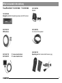
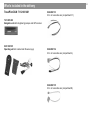
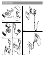
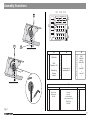
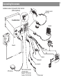
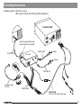
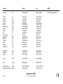
Navigation
TravelPilot DX-N
7 612 001 460 Black monitor
7 612 001 461 Upgrade without monitor
7 612 001 462 Silver monitor
Installation instructions
Safety precautions
Congratulations on your purchase of this Blaupunkt product. Thank you for the trust you are putting into our brand!
The following installation instructions are intended to help you getting the best performance from your Blaupunkt product. To avoid the
aggravation of costly mistakes and serious damage to your system, please read all of the instructions carefully before you begin.. If
you’re not confident that you can install the unit correctly, have it installed by a qualified Blaupunkt installation technician.
Installation and connection regulations
While connecting and installing this equipment, make sure to disconnect the negative terminal of the battery.
Important!
Observe all safety precautions provided by the automobile manufacturer (alarm systems, immobilisers, airbag)!
Before drilling the holes for mounting and wiring, make sure that no existing wiring or vehicle parts will be damaged
(e.g. petrol tank, petrol lines).
Use wire bushings for all sharp-edged holes.
To avoid interference, make sure to lay the wiring far enough away from the wire harness.
Attach a fuse to the positive supply wire at a maximum of 30 cm from the battery to protect the battery and the positive
supply wire in the event of a short circuit.
The navigation equipment is suitable for vehicles with:
• 12 V battery power
• Negative pole on the vehicle body
2
Contents
Safety precautions ..............2
Installation ...........................4
Description .......................................... 4
Notes on how the system functions ... 4
Installation preparations .................... 4
Installing
the navigation unit ..............5
Where to install the navigation unit .... 5
Positive connection ............................ 5
Negative connection .......................... 5
Installing the GPS antenna ..5
Important installation
information for the
speedometer signal ............7
Connecting the speedometer
signal .................................................... 7
Connecting the back-up
lights signal wire .................7
Video input assignment ......8
Safety instructions ............................. 6
Technical data ...................10
Installing the speaker .........6
Installing the control unit ...7
DX-N and RC 09H
in the front ......................................... 18
Connecting the sensors .. 19
DX-N in the car boot,
TMC tuner box and
RC 09H in the front ........................... 19
Calibration ...........................9
Calibrating the Gala curve ................. 9
Display de-installation ....................... 6
Connecting the sensors .. 18
System test
after installation ..................8
Installing the display ...........6
Display installation ............................. 6
Assembly illustrations ..... 16
Basic navigation unit ....................... 10
5" colour display ............................... 10
What’s included
in the delivery ....................11
3
Allgemeines Kurzanlei- Zieleingabe
Touren
Zielspeicher Einstellun-
Anhang
4
Installation
Description
Installation preparations
The TravelPilot DX-N navigation system is an independent system with an integrated gyroscope. After a destination has been
entered and activated, the system delivers visual driving recommendations as pictograms on a 5" colour monitor and spoken
driving information via a separate speaker well in advance of
any turns or changes in driving direction required. In this way,
the system guides the motorist from his/her starting point on the
best route to the selected destination.
All of the available functions are described in the specifications
of the CD-ROM used.
Before starting the installation, check to see that
no parts from the installation pack are missing. ........ page 11
Notes on how the system functions
The TravelPilot is equipped with an automatic calibration
feature which is required to determine the current vehicle
position. Depending on the GPS reception available, the
calibration is completed after the vehicle has been driven
approx. 15 km. Driving along a winding route (in the city),
which is indicated on the monitor on a map, accelerates the
calibration.
The speedometer signal connection in the vehicle allows the
system to determine the distance driven. If there is no speedometer signal, it will be necessary to have a route sensor installed by an authorised customer service centre.
In this case, you will have to order a sensor kit (route sensor, magnet strips, bracket, plug and installation instructions) from your dealer.
Order No.: 7 607 611 093
The following steps must be completed to install the equipment:
•
•
•
•
•
•
•
Installing the navigation unit (computer) .......... page 5
Installing the GPS antenna ................................. page 5
Installing the display (monitor) .......................... page 6
Installing the speaker .......................................... page 6
Installing the operating unit ............................... page 7
Installing the speedometer signal wire ............. page 7
Installing the back-up lights signal wire ........... page 7
Installation
Positive connection
Installing the navigation unit
Where to install the navigation unit
Important!
Before inserting the TravelPilot, you have to make sure that
the gyroscope is positioned horizontally (see Fig. 7, page 17).
The TravelPilot DX-N can be installed in the car radio compartment in the vehicle (installation depth 218 mm). You will need
an installation bracket (order no. 8 601 310 555) (see Fig. 1 page
16).
For vehicles without a DIN compartment, a universal equipment
housing has been included (see Fig. 1.1 page 16). Check to see
which method of installation is required for the vehicle and, if
necessary, use a vehicle-specific installation kit.
If a tuner box or remote control is to be added to the TravelPilot at a later date, the connection wire included
(8 604 492 522) could be installed at this point.
When selecting an installation location, you must remember that
the navigation unit has to be built into the vehicle body.
Installation position:
right / left
slope to the rear
min. -5˚ / max. +5˚
min. -3˚ / max. +100˚
Connect the navigation unit to continuous plus and the positive
connection to the ignition.
Lay the continuous plus wire (red) to the battery (do not lay the
wire directly along any wire harnesses). Connect a fuse holder
to protect the positive wire at a maximum of 30 cm from the
vehicle battery (if necessary, drill a hole in the splashback and
use the necessary wire bushing). Connect the switching plus
wire (black) to terminal 15 on the fuse holder (plus is switched
by the ignition) behind the fuse.
Negative connection
Screw the negative wire (brown) directly to the vehicle body.
Scratch the contact points on the ground down to the metal and
grease it with graphite grease (important for a good ground).
Installing the GPS antenna
Install the antenna according to the enclosed instructions.
If the GPS antenna is installed inside the vehicle, there is no
guarantee that the system will function properly.
A fan has been built into the back of the unit to cool it when
it overheats. To allow for sufficient air circulation, make sure
that the air vents are not blocked. Use only the hole strips
to attach the unit to the mounting bolt.
Make sure that there is enough room to insert and remove the
navigation CD.
5
Allgemeines Kurzanlei- Zieleingabe
Touren
Zielspeicher Einstellun-
Anhang
6
Installation
Installing the display
Safety instructions
Never grease or oil the ball-and-socket joint.
The monitor cable must be laid so that it is not subjected
to any tensile strains or other loads.
Important!
Do not mount the monitor within the inflation range of
the airbags (on the driver’s side, the passenger side or
the side airbags) or where it might strike the head or knees
of anyone in the vehicle in the event of an accident!
Before drilling the holes for the mounting screws and
wiring, make sure that no damage will be done to covered wiring, the petrol tank or fuel lines!
Display installation
Fig. 3 The display is mounted on the dashboard or console using the enclosed ball-and-socket base.
Fig. 4 The display is mounted directly on a console (telephone
console) with the ball joint.
Fig. 5 The display is mounted using the swan neck fitting 7 612
001 204 and the ball-and-socket base. To do so, you must
disassemble the rear panel of the display.
A 10 mm wide hole must be drilled at the mounting position to accommodate the cable. When the cable is installed, you must ensure it will safe from being tugged or
stretched or from being exposed to any other loads.
Display de-installation (Fig. 6)
1. Unscrew the four screws on the back of the display and remove the rear panel.
2. Pull out the plugs carefully and push them through the mounting base.
3. Then use the mounting material you require.
Installing the speaker
Install the speaker used for the spoken driving recommendations in the footwell of the vehicle.
Important!
Make sure that the vehicle operating elements remain easily
accessible and are not obstructed in any way by the connection
cable and the location of the speaker (gear stick, hand brake,
accelerator, clutch or brake pedals, etc.)!
Important!
Before drilling the holes for the mounting screws, make sure that
no damage will be done to covered wiring, the petrol tank or fuel
lines!
Installation
Installing the control unit
Mount the control unit bracket in a location where the control
unit will be easily accessible, e.g. on the centre console.
Important!
Do not mount the control unit within the inflation range of the
airbags (on the driver’s side, the passenger side or the side airbags) or where it might strike the head or knees of anyone in the
vehicle in the event of an accident!
Before drilling the holes for the mounting screws, make sure that
no damage will be done to covered wiring, the petrol tank or fuel
lines!
Make sure that the vehicle operating elements remain easily
accessible and are not obstructed in any way (gear stick, hand
brake, etc.)!
Important installation information for
the speedometer signal
When connecting the speedometer signal, make sure to
observe the following information:
1. Where to find the signal: For many vehicles, the speedometer signal can be found in the vehicle-specific car radio plug.
Contact the customer service of the vehicle manufacturer or
an authorised navigation dealer to find out what the exact pin
allocation is.
3. Important:
We assume no responsibility for any equipment that is installed incorrectly and the consequences thereof!
Connecting the speedometer signal
Important: This connection should be made by an authorised
customer service centre.
The connection is made with the speedometer signal wire
(8 618 841 988) to the vehicle-specific speedometer signal connection. (see connection diagram, page 18).
Connecting the back-up lights signal
wire
Important : This connection should be made by an authorised
customer service centre.
The connection is made with the back-up lights signal wire
(8 618 842 033) to the vehicle back-up lights. Make sure that
there are +12V at the connection when the vehicle is backing up
(see connection diagram, page 18).
Important:
We assume no responsibility for any equipment that is installed
incorrectly and the consequences thereof!
2. Do not use the speedometer signal from ABS control units or
control circuits.
7
Allgemeines Kurzanlei- Zieleingabe
Touren
Zielspeicher Einstellun-
Anhang
8
Installation
Video input assignment
System test after installation
The video input socket is intended for future applications. For
information on connection options, please contact a Blaupunkt
dealer or our hotline. See connection diagram for assignment.
The system test allows you to test the external connections to
see that they are working correctly.
Proceed as follows:
15
10
1
1. Turn off TravelPilot DX-N
2. Press the
Pin Description
Input /
Ouput
Comment
1
EXT_R
E
Red input
2
EXT_G
E
Green input
3
EXT_B
E
Blue input
4
V_GND
E
Video earth
5
EXT_SYNC
E
Synchronisation input
6
NC
-
7
U14
A
8
STANDARD SWITCH
E
9
EARTH
A
10
NC
11
N. B.
12
Switch on EXT.
E
13
UB
A
14
Screen switch
A
15
MP_U53
A
Low = PAL Format / High = NTSC Format
Low = Off / High = On
Low = Mirror image / High = Normal image
button and keep it pressed.
3. Turn on the TravelPilot DX-N and release the
the service menu appears.
4. Using the
OK button.
button, select the test menu
button when
and press the
5. Now select the required test using the
or
button, press
the OK button and follow the on-screen instructions.
If the test was completed successfully, the menu item will be
labelled with a tick. If an error occurs, an appropriate notice
will be displayed.
6. Close the service menu by pressing the
button.
Calibration
Calibration
After installation, the TravelPilot DX-N must be calibrated. You
will find the procedure for this described in the operating instructions.
Calibrating the Gala curve
After the TravelPilot DX-N is calibrated, the values that were
determined must be transferred to the control unit software so
that the Gala feature (sound-dependent volume adjustment)
works correctly.
Please proceed as follows:
1. Turn off TravelPilot DX-N.
2. Press the
button and keep it pressed.
3. Turn on the TravelPilot DX-N and release the
the service menu appears.
button when
4. Using the
button, select the settings menu
and press
the OK button. This procedure transfers the calibration values that were previously determined to the control unit.
5. Close the service menu by pressing the
button.
9
Allgemeines Kurzanlei- Zieleingabe
Touren
Zielspeicher Einstellun-
Anhang
10
Technical data
5" colour display
Basic navigation unit
Rated voltage (Urat)
14 V / DC
TFT active matrix LCD
Rated current (I)
Typically 0.55 A (Imax 1.05 A)
Contrast control
Manual on rocker
Stand-by current
Typically 0.35 A
Brightness control
Speech output /
volume
Automatic by phototransistor,
manual on rocker
Max. 3 Watt/4 Ohm
Mounting
Universal ball-and-socket joint
Width
148 mm (without cable and base)
Time to first position
computation
CD-ROM drive
(Warm start, memory refresh)
< 2 minutes; (cold start, memory
clear) < 15 minutes
For 12 cm CD to DIN EN 60908
only
Operating temperature
-15°C to +60°C
Mounting orientation
right / left
min. - 5˚ / max. + 5˚
slope to the rear
min. - 3˚ / max. +100˚
Width
187.5 mm
Height
58.5 mm
Depth
174.4 mm
Weight
1.35 kg
(12.5 cm diagonal)
Height
105 mm (without cable and base)
Depth
51 mm (without cable and base)
Cable length
5.5 m
Subject to modification!
What’s included in the delivery
TravelPilot DX-N 7 612 001 460 / 7 612 001 462
8 618 842 586
Speaker
7 612 001 489
Navigation unit with integrated gyroscope and GPS receiver
8 618 840 754
4 m of wire for the speaker
8 627 000 013
GPS-antenna
8 618 842 735
8 618 842 667
8 601 360 105
Operating unit incl. bracket and IR sensor (eye)
5"- colour monitor black
5"- colour monitor silver
11
Allgemeines Kurzanlei- Zieleingabe
Touren
Zielspeicher Einstellun-
Anhang
12
What’s included in the delivery
8 618 841 412
6 m of DC wire
8 618 841 988
4 m of speedometer wire
brown
white
8 618 842 033
4.5 m of back-up lights signal wire
8 604 492 513
0.3 m of connection wire (compartment C1)
blue
yellow
What’s included in the delivery
8 604 492 514
0.3 m of connection wire (compartment A)
8 606 590 212
Universal equipment housing
8 604 492 522
Tuner box / RC 09 connection wire
8 604 492 515
0.3 m of connection wire (compartment B)
13
Allgemeines Kurzanlei- Zieleingabe
Touren
Zielspeicher Einstellun-
Anhang
14
What’s included in the delivery
TravelPilot DX-N 7 612 001 461
8 604 492 513
0.3 m of connection wire (compartment C1)
7 612 001 489
Navigation unit with integrated gyroscope and GPS receiver
8 601 360 105
Operating unit incl. bracket and IR sensor (eye)
8 604 492 514
0.3 m of connection wire (compartment A)
8 604 492 515
0.3 m of connection wire (compartment B)
What’s included in the delivery
8 606 590 212
Universal equipment housing
8 604 492 522
Tuner box / RC 09 connection wire
15
Allgemeines Kurzanlei- Zieleingabe
Touren
Zielspeicher Einstellun-
Anhang
16
Assembly illustrations
8 601 310 555
Fig. 1
Fig. 5
Fig. 1.1
Fig. 2
Fig. 3
Fig. 4
Fig. 6
Assembly illustrations
C-1
6
10
3
2
7
8
5
6
1
3
4
2
C-3
13 16 19
9 12
8 11
5
1
D
C-2
7 10
4
2
9
1
C
15 18
14 17 20
3
5
7
4
6
8
1
3
5
7
2
4
6
8
B
+100
–5°
A
90˚
A
1
2
3
4
5
6
7
8
+100
o.k.
–5°
Gala/Tacho
–
RFLS
Dauerplus +12V
–
Beleuchtung
Zündung
Masse
D
B
1
2
3
4
5
6
7
8
–
–
–
–
Lautsprecher LF+
Lautsprecher LF–
–
1
2
3
4
5
6
7
8
9
10
GND
Data Out
Data In
Mute (AR)
—
—
Line GND
—
Line Out
—
90˚
C
C1
–10°
1
2
3
4
5
6
00
+1
Wheel sensor
Wheel sensor
FB GND
-
C2
7
8
9
10
11
12
CAN High
CAN Low
+12V Permanent
+12V switched (RC 09)
PPM (RC 09)
PPM-GND
Fig. 7
C3
13
14
15
16
17
18
19
20
–
–
–
–
–
–
–
–
17
Allgemeines Kurzanlei- Zieleingabe
Touren
Zielspeicher Einstellun-
Anhang
18
Connecting the sensors
Installation location: DX-N and RC 09H in the front
(DIN compartment)
IR remote control
RC 09 H
X
TravelPilot DX-N
A
Speaker
X
5"
Video-IN
black
red
Kl.30
RFLS
Tachosignal
not connected
12 V
GPS antenna
TMC car radio connection
(Accessory cable
Skyline II: 7 607 612 093;
Funline II: 7 607 613 093)
Wheel sensor
Connecting the sensors
Installation location : DX-N in the car boot
TMC tuner box and RC 09H in the front (DIN compartment)
5A
A
TravelPilot DX-N
Attach the ground cable using
the torx-head screw provided
8 604 492 533
8 604 492 540
Radio
Tuner box
Antenna
8 604 492 532
+ 12V
IR remote control
RC 09 H
8 604 492 523
8 604 492 522
Tuner box / RC 09 connection wire
19
Allgemeines Kurzanlei- Zieleingabe
Touren
Zielspeicher Einstellun-
Anhang
Country:
Phone:
Fax:
WWW:
http://www.blaupunkt.com
Germany
(D)
0180-5000225
05121-49 4002
Austria
Belgium
Denmark
Finland
France
Great Britain
Greece
Ireland
Italy
Luxembourg
Netherland
Norway
Portugal
Spain
Sweden
Switzerland
(A)
(B)
(DK)
(FIN)
(F)
(GB)
(GR)
(IRL)
(I)
(L)
(NL)
(N)
(P)
(E)
(S)
(CH)
01-610 390
02-525 5454
44 898 360
09-435 991
01-4010 7007
01-89583 8880
0800-550 6550
01-4149400
02-369 6331
40 4078
023-565 6348
66-817 000
01-2185 00144
902-120234
08-7501500
01-8471644
01-610 393 91
02-525 5263
44-898 644
09-435 99236
01-4010 7320
01-89583 8394
01-576 9473
01-4598830
02-369 6464
40 2085
023-565 6331
66-817 157
01-2185 11111
916-467952
08-7501810
01-8471650
Czech. Rep.
Hungary
Poland
(CZ)
(H)
(PL)
02-6130 0441
01-333 9575
0800-118922
02-6130 0514
01-324 8756
022-8771260
Turkey
(TR)
0212-3350677
0212-3460040
USA
(USA)
800-2662528
708-6817188
+55-19 3745 2769
+604-6382 474
+55-19 3745 2773
+604-6413 640
Brasil (Mercosur)
(BR)
Malaysia (Asia Pacific) (MAL)
Blaupunkt GmbH
08/ 2001
CM/PSS 2 8 622 402 141 D (GB)