1
User's Manual
Copyright © DENSO, 1997
All rights reserved. No part of this publication may be reproduced in any form or by
any means without permission in writing from the publisher.
Specifications are subject to change without prior notice.
Microsoft®, MS-DOS®, and QuickBASIC® are registered trademarks of Microsoft Corporation.
IBM®, PC/AT®, and PS/2® are registered trademarks of International Business Machines Corporation.
BHT, CU, BHT-protocol, BHT-Ir protocol, and BHT-BASIC 3.0 are trademarks of DENSO
CORPORATION.
Preface
Please READ through these operating instructions carefully. It will enable you to
operate your BHT-6000 correctly.
After you have finished reading the instructions, keep this manual handy for speedy
reference.
The BHT-6000 series is available in two types: the normal-range type and long-range
type (BHT-6000D). In this manual, both types are called the BHT-6000 unless otherwise
specified.
i
How this book is organized
This manual is made up of five chapters and appendices.
Chapter 1. Quick Guide
Describes the basic operating method of the BHT-6000 and the related notes.
Chapter 2. Getting Started the BHT-6000 and System Mode
Summarizes the BHT-6000 system configuration and describes the operation including
preparation and System Mode (which is required for the efficient use of application
programs).
Chapter 3. Communications Operations of BHT-6000
Describes the communications operations of the BHT-6000--the RS-232C interface
specifications, the basic communications specifications, and the communications
protocols--for data transmission with the host computer or other devices.
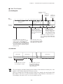
Chapter 4. Error Messages
Lists the error messages which will appear on the LCD if some error occurs in the BHT6000.
Chapter 5. Handling the CU-6000 (Option)
Describes the handling procedure of the CU-6000, the interfacing with the host computer, and the charging of the Ni-MH battery cartridge.
Appendix A: Specifications
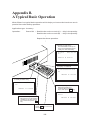
Appendix B: A Typical Basic Operation
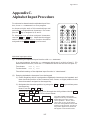
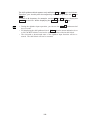
Appendix C: Alphabet Input Procedure
ii
■ Related Publications
BHT-BASIC 3.0 Programmer's Manual
Transfer Utility Guide
Ir-Transfer Utility C Guide
■ Screen Indication
The lettering in the screens in this manual is a little different from that in the actual
screens. File names used are only for description purpose, so they will not appear if
you have not set files having those names.
iii
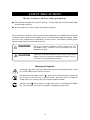
SAFETY PRECAUTIONS
Be sure to observe all these safety precautions.
■ Please READ through this manual carefully. It will enable you to use the BHT-6000
and CU-6000 correctly.
■ Always keep this manual nearby for speedy reference.
Strict observance of these warning and caution indications are a MUST for preventing
accidents which could result in bodily injury and substantial property damage. Make
sure you fully understand all definitions of these terms and related symbols given
below, before you proceed to the text itself.
WARNING
Alerts you to those conditions which could cause serious bodily injury or death if the instructions are not
followed correctly.
CAUTION
Alerts you to those conditions which could cause minor
bodily injury or substantial property damage if the instructions are not followed correctly.
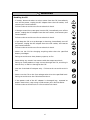
Meaning of Symbols
A triangle (
) with a picture inside alerts you to a warning of danger. Here
you see the warning for electrical shock.
A diagonal line through a circle ( ) alerts you to something you should not
do; it may or may not have a picture inside. Here you see a screwdriver
inside the circle, meaning that you should not disassemble.
A black circle ( ) with a picture inside alerts you to something you MUST
do. This example shows that you MUST unplug the power cord.
iv
WARNING
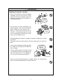
Handling the battery cartridge
• Never disassemble or heat the battery
cartridge, nor put it into fire or water;
doing so could cause battery-rupture or
leakage of battery fluid, resulting in a
fire or bodily injury.
Never
put me
into fire!
• Do not carry or store the battery cartridge together with metallic ball-point
pens, necklaces, coins, hairpins, etc.
Do not
shortcircuit
me!
Doing so could short-circuit the terminal pins, causing the batteries to rupture or the battery fluid to leak, resulting in a fire or bodily injury.
• Avoid dropping the battery cartridge or letting it undergo any shock
or impact.
Doing so could cause the batteries to break, generate heat, rupture or
burn.
• Only use the dedicated charger (CU-6001
or C-600) for charging the Ni-MH battery cartridge.
Charge only
with the
dedicated
device.
Using a different type of charger could
cause battery-rupture or leakage of battery fluid and result in a fire, bodily injury, or serious damage to property.
Undedicated
Dedicated
• Never charge the Ni-MH battery cartridge where any inflammable
gases may be emitted; doing so could cause fire.
v
WARNING
Handling the CU
• If smoke, abnormal odors or noises come from the CU, immediately
turn off the power, unplug the AC adapter from the wall socket, and
contact your nearest dealer.
Failure to do so could cause fire or electrical shock.
• If foreign material or water gets into the CU, immediately turn off the
power, unplug the AC adapter from the wall socket, and contact your
nearest dealer.
Failure to do so could cause fire or electrical shock.
• If you drop the CU so as to damage its housing, immediately turn off
the power, unplug the AC adapter from the wall socket, and contact
your nearest dealer.
Failure to do so could cause fire or electrical shock.
• Never use the CU for charging anything other than the specified
battery cartridges.
Doing so could cause heat, battery-rupture, or fire.
• Never bring any metals into contact with the output terminals.
Doing so could produce a large current through the CU, resulting in
heat or fire, as well as damage to the CU.
• Use the furnished AC adapter only. Failure to do so could result in
fire.
• Never use the CU on the line voltage other than the specified level.
Doing so could cause the CU to break or burn.
• If the power cord of the AC adapter is damaged (e.g., exposed or
broken lead wires), stop using it and contact your nearest dealer.
Failure to do so could result in a fire or electrical shock.
vi
CAUTION
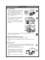
Basic handling tips
• Never put the BHT in places where there
are excessively high temperatures, such
as inside closed-up automobiles, or in
places exposed to direct sunlight.
I’m burning
up!
Doing so could affect the housing or
parts, resulting in a fire.
• Avoid using the BHT in extremely humid or dusty areas, or where there are
drastic temperature changes.
This
humidity
is killing
me!
Hothouse
Moisture or dust will get into the BHT,
resulting in malfunction, fire or electrical shock.
Refrigeration
Refrigeration
I’m
freezing!
Refrigeration
• Never disassemble or modify the BHT; doing so could result in an
accident such as break or fire.
Never
disassemble
Handling the Ni-MH battery cartridge
• Never charge a wet or damp Ni-MH battery cartridge.
Doing so could cause the batteries to break, generate heat, rupture,
or burn.
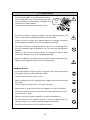
Handling the BHT
• If smoke, abnormal odors or noises come from the BHT, immediately
turn off the power, pull out the dry batteries or the battery cartridge,
and contact your nearest dealer.
Failure to do so could cause smoke or fire.
• If foreign material or water gets into the
BHT, immediately turn off the power,
pull out the dry batteries or the battery
cartridge, and contact your nearest
dealer.
Failure to do so could cause smoke or
fire.
vii
Keep me
away from
water!
CAUTION
• If you drop the BHT so as to damage its housing, immediately turn off the power, pull out
the dry batteries or the battery cartridge, and
contact your nearest dealer.
Do not
drop
me!
Failure to do so could cause smoke or fire.
• For those machines using dry batteries, do not mistake the plus and
minus marks when loading dry batteries into the BHT.
Failure to do so could cause battery-rupture or leakage of battery
fluid, resulting in bodily injury, fire, or property damage.
• For those machines using dry batteries, do not use anything other
than the specified type of batteries, nor use new and old batteries
together.
Doing so could cause battery-rupture or leakage of battery fluid,
resulting in bodily injury, fire, or property damage.
• Do not use batteries or power sources other than the specified ones;
doing so could generate heat or cause malfunction.
Handling the CU
• If you will not be using the CU for a long time, be sure to unplug the
AC adapter from the wall socket for safety.
Failure to do so could result in a fire.
• When caring for the CU, unplug the AC adapter from the wall socket
for safety.
Failure to do so could result in an electrical shock.
• Never cover or wrap up the CU or AC adapter in a cloth or blanket.
Doing so could cause the unit to heat up inside, deforming its housing, resulting in a fire.
Always use the CU and AC adapter in a well-ventilated area.
• Do not place the CU anyplace where it may be subjected to oily
smoke or steam, e.g., near a cooking range or humidifier.
Doing so could result in a fire or electrical shock.
viii
CAUTION
• Keep the power cord away from any heating equipment.
Failure to do so could melt the sheathing, resulting in a fire or
electrical shock.
• Do not insert or drop foreign materials such as metals or anything
inflammable through the openings (vents or battery cartridge slot)
into the CU.
Doing so could result in a fire or electrical shock.
■ DENSO WAVE INCORPORATED does not assume any product liability arising out
of, or in connection with, the application or use of any product, circuit, or application
described herein.
■ Intellectual Property Precaution
DENSO WAVE INCORPORATED ("DENSO WAVE") takes reasonable precautions to
ensure its products do not infringe upon any patent of other intellectual property
rights of other(s), but DENSO WAVE cannot be responsible for any patent or other
intellectual property right infringement(s) or violation(s) which arise from (i) the
use of DENSO WAVE's product(s) in connection or in combination with other
component(s), product(s), data processing system(s) or equipment or software not
supplied from DENSO WAVE; (ii) the use of DENSO WAVE's products in a manner
for which the same were not intended nor designed; or (iii) any modification of
DENSO WAVE's products by other(s) than DENSO WAVE.
ix
■ Proper Care of the BHT and CU
Clean the housing, charge terminals, and battery cartridge terminals with a dry, soft
cloth. (When taking care of the CU-6000, unplug the AC adapter from the wall socket
for safety.)
•
•
Never use benzene, alcohol, or other organic solvents. The housing may be
marred or the paint may come off.
Never rub or strike the liquid crystal display (LCD) with anything hard. The LCD
surface will be easily scratched or broken.
Take care of
me with a dry
soft cloth.
NO WAY!!
•
When cleaning the keypad, do not scrub
the surface too hard, and do not pull on
the keys. Doing so may break the keys
or cause the keypad to dislocate.
•
If the BHT or CU becomes smudged, moisten a soft cloth with neutral detergent and
wring it out thoroughly. Wipe the BHT or CU with the cloth and then go over it
again with a dry cloth.
Thinner Benzine
Dust or dirt accumulating on the clear plate of the bar-code reading window will affect
reading performance. If you use the BHT-6000 in dusty areas, therefore, periodically
check the clear plate of the bar-code reading window and clean it if dusty.
•
To clean the plate, first blow the dust away with an air brush. Then wipe the plate
with a cotton swab or the similar soft one gently.
•
If sand or hard particles have accumulated, never rub the plate; doing so will
scratch or damage it. Blow the particles away with an air brush or a soft brush.
■ Limited Warranty on Software Products
In no event will DENSO WAVE be liable for direct, indirect, special, incidental, or
consequential damages (including imaginary profits or damages resulting from interruption of operation or loss of business information) resulting from any defect in the
software or its documentation or resulting from inability to apply the software or its
documentation.
x
Content Overviews
Preface ................................................................................................................................
i
How this book is organized .............................................................................................
ii
SAFETY PRECAUTIONS ....................................................................................................
iv
Chapter 1. Quick Guide ...................................................................................................
1
1.1
Reading Bar Codes ...................................................................................................
2
1.2
Using the Hand Strap and Clip ...............................................................................
3
1.3
Setting the Backlight ................................................................................................
4
1.4
Using the Keypad .....................................................................................................
5
1.5
Communicating via the Optical Interface ..............................................................
6
Chapter 2. Getting Started the BHT-6000 and System Mode ....................................
7
2.1
BHT-6000 System Configuration ............................................................................
8
2.2
Infrared Communications ........................................................................................ 13
2.3
Components and Functions .................................................................................... 14
2.4
Preparation ................................................................................................................ 16
2.4.1 Setting-up 1: Loading Dry Batteries or Battery Cartridge .......................... 16
2.4.2 Setting-up 2: Initializing the BHT-6000 and Setting the
Calendar Clock .................................................................................................. 21
2.4.3 Adjusting the LCD Contrast & Beeper Volume, and
Displaying the Battery Voltage Level ............................................................. 27
2.5
Operating in System Mode ..................................................................................... 29
2.5.1 Starting System Mode ..................................................................................... 29
2.5.2 Operating in System Mode ............................................................................. 32
2.5.3 Detailed Description of the Functions in System Mode .............................. 34
Chapter 3. Communications Operations of BHT-6000 ................................................ 81
3.1
RS-232C Interface Specifications ........................................................................... 82
3.2
Basic Communications Specifications and Parameters ...................................... 84
3.2.1 Basic Communications Specifications ........................................................... 84
3.2.2 Communications Parameters .......................................................................... 86
3.3
Communications Protocols ..................................................................................... 87
3.3.1 BHT-protocol ..................................................................................................... 87
3.3.2 BHT-Ir Protocol ................................................................................................. 103
Chapter 4. Error Messages .............................................................................................. 121
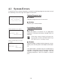
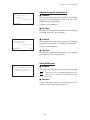
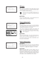
4.1
System Errors ........................................................................................................... 122
4.2
Errors in System Mode ............................................................................................ 126
Chapter 5. Handling the CU-6000 (Option) ................................................................... 133
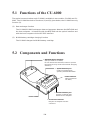
5.1
Functions of the CU-6000 ........................................................................................ 134
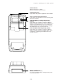
5.2
Components and Functions .................................................................................... 134
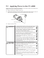
5.3
Applying Power to the CU-6001 ............................................................................. 136
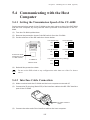
5.4
Communicating with the Host Computer.............................................................. 137
5.4.1 Setting the Transmission Speed of the CU-6000 ......................................... 137
5.4.2 Interface Cable Connection ............................................................................. 137
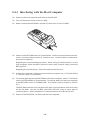
5.4.3 Interfacing with the Host Computer ............................................................... 138
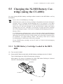
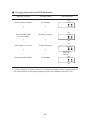
5.5
Charging the Ni-MH Battery Cartridge (using the CU-6001) ............................... 139
5.5.1 Ni-MH Battery Cartridge Loaded in the BHT-6000 ....................................... 139
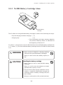
5.5.2 Ni-MH Battery Cartridge Alone ....................................................................... 141
5.6
RS-232C Interface Specifications ........................................................................... 144
Appendices ......................................................................................................................... 147
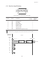
Appendix A. Specifications ............................................................................................. 148
A.1
BHT-6000 ........................................................................................................... 148
A.2
CU-6000 ............................................................................................................. 154
Appendix B. A Typical Basic Operation ......................................................................... 156
Appendix C. Alphabet Input Procedure ......................................................................... 157
Index .................................................................................................................................... 159
Chapter 1. Quick Guide
Chapter 2. Getting Started the BHT-6000 and System Mode
Chapter 3. Communications Operations of BHT-6000
Chapter 4. Error Messages
Chapter 5. Handling the CU-6000 (Option)
Appendices
Chapter 1. Quick Guide
Chapter 1
Quick Guide
This chapter describes the basic operating method of the BHT-6000 and the related
notes.
1.1
Reading Bar Codes ............................................................................................................. 2
1.2
Using the Hand Strap and Clip .......................................................................................... 3
1.3
Setting the Backlight .......................................................................................................... 4
1.4
Using the Keypad ............................................................................................................... 5
1.5
Communicating via the Optical Interface ......................................................................... 6
1
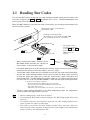
1.1 Reading Bar Codes
Turn on the BHT power, bring the bar-code reading window up to the bar code to be
scanned, and press the M1 or M2 key (Magic key 1 or 2)*. The BHT-6000 lights the
illumination LED and reads the bar code.
When the BHT-6000 has read the bar code successfully, the reading confirmation LED
will illuminate in green.
Illumination range covered by the
illumination LED
Reading confirmation LED
(Illuminates in green when the BHT-6000
has read the bar code successfully.)
* The trigger switch
function is assigned
to both M1 and M2
keys when the BHT6000 leaves the
factory.
M1 key*
(Magic key 1)
PW key
• When reading bar codes, slightly tilt the
BHT-6000 down towards you relative to
those codes, as illustrated at right.
• If the BHT-6000 fails to read, change the reading angle of the bar-code reading
window or the distance from bar codes, and try it again.
• To read bar codes wider than the readable area of the bar-code reading window,
pull the bar-code reading window away from bar codes for long-range scanning
so that the entire bar code comes into the illumination range covered by the
illumination LED. The BHT-6000 can read bar codes at a maximum distance of 24
cm (9.4") [35 cm (13.8") for the BHT-6000D]** from the bar-code reading window.
** Under the following conditions:
- Ambient illuminance: 500 lux (fluorescent lamp)
- ITF conforming to the UPC Shipping Container Code
- PCS value: 0.9 or more
- Minimum narrow bar width: 1.2 mm min. (47.2 mils min.)
• The bar code reading procedure may differ depending upon the application
used, so follow the application’s manual.
NOTE
• Before reading labels, clean them if stained.
• Avoid using the BHT-6000 in direct sunlight. The BHT-6000 might fail to read
correctly.
• To read bar codes on curved surfaces, apply the bar-code reading window to the
center of each bar code at a right angle.
• The further you pull the bar-code reading window away from bar codes, the
wider the quiet zones required, in relation to bar code lengths in the illumination
range covered by the illumination LED.
2
Chapter 1. Quick Guide
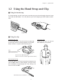
1.2 Using the Hand Strap and Clip
■ Using the hand strap
As shown below, set the hand strap, and then put your hand through the hand strap
and hold the BHT-6000. This will prevent you from dropping the BHT-6000 accidentally.
Hand strap
■ Using the clip
Attaching the clip
Using the clip
As illustrated below, first fit the left (or right) tab
of the clip into the matching groove of the BHT
body and then snap the other tab into place.
With the clip, you can clip the
BHT-6000 on your pocket.
Tab
(There is one each on the
right and left ends.)
Groove in the BHT body
(There is one each on the right and left sides.)
Removing the clip
Insert the tip of a flat-head screwdriver between the
clip and BHT body as shown below, and then twist
the screwdriver to disengage the clip, taking care
not to scratch the BHT.
Small flat-head screwdriver
3
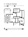
1.3 Setting the Backlight
Pressing the M1 key while holding down SF (Shift) key activates or deactivates the
backlight function.
Backlight OFF
(The backlight function
is OFF when you power
on the terminal.)
Press M1 while
holding down SF .
M1
ABC
DEF
GHI
JKL
MNO
PQR
STU
VWX
Y Z Sp
+-*
/$%
Backlight ON
Press M1 while
holding down SF .
If no key is
pressed for at
least 3 seconds.
Press any key (except
for the simultaneous
depression of M1
and SF ).
SF
Backlight OFF
(The backlight function
is kept ON.)
NOTE
Press M1 while
holding down SF .
In user programs, you can select the key to be used for activating or deactivating
the backlight function (instead of the default: combination of SF and
M1 ), as well as modifying the ON-duration of the backlight before the automatic
turning-off.
4
Chapter 1. Quick Guide
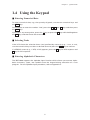
1.4 Using the Keypad
■ Entering Numerical Data
To enter numerical data, e.g., the quantity of goods, use the ten numerical keys and
the ENT key.
For example, to enter the number "120," press the 1 , 2 and 0 keys and then press
the ENT key.
If you key in any wrong value, press the C key (or press the C key while holding down
the SF key) and then enter the correct one.
■ Selecting Tasks
If the LCD shows the selection items (xxx) prefixed by numerals (e.g., 1: xxx, 2: xxx),
use the numerical keys to select a desired item and press the ENT key to execute.
If a YES/NO screen (e.g., 1: YES, 2: NO) appears, press the 1 key for YES response and
2 key for NO response.
■ Entering Alphabetic Characters
The BHT-6000 supports the alphabet input function which allows you to enter alphabetic characters, space, and symbols from the keypad during execution of a user
program. For the alphabet input procedure, refer to Appendix C.
5
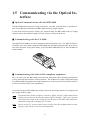
1.5 Communicating via the Optical Interface
■ Optical Communications with the BHT-6000
The BHT-6000 communicates using an IR beam, so make sure that there is no obstruction in the light path between the BHT-6000 and any target stations.
In the IrDA communications mode, you need to keep the BHT-6000 and any target
stations within the effective light emission range, usually 10 to 80 cm.
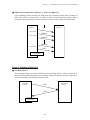
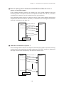
■ Communicating with the CU-6000
The optional CU-6000 is an IrDA-compliant communications unit. For optical communications, you may either keep the BHT-6000 and CU-6000 separated by 10 to 80 cm
with their IR ports facing each other, or put the BHT-6000 directly on the CU-6000 as
shown below.
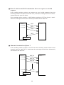
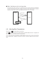
■ Communicating with other IrDA-compliant equipment
You can also have the BHT-6000 communicate with other IrDA-compliant equipment
just by aligning their IR ports with each other. The effective IR range and IR port angle
may differ depending upon the target equipment, so observe the instructions given in
manuals furnished with such equipment.
If transfer using the BHT-6000 fails, bring it closer to the target station or change the IR
port angle, and try again.
NOTE
Communications failures might be caused by highly intensive light emitted from
ceiling (inverter-driven fluorescent) lamps or direct sunlight. Take care to prevent
such interference light from coming into the IR ports of the BHT-6000 and IrDAcompliant equipment, including the CU-6000.
NOTE
Do not use any TV remote control in the vicinity of the IR communications system.
Doing so may interfere with the communications.
6
Chapter 2. Getting Started the BHT-6000 and System Mode
Chapter 2
Getting Started the BHT-6000 and System Mode
This chapter summarizes the BHT-6000 system configuration and describes the operation including preparation and System Mode (which is required for the efficient use of
application programs).
2.1
BHT-6000 System Configuration ............................................................................................................ 8
2.2
Infrared Communications .................................................................................................................... 13
2.3
Components and Functions ................................................................................................................. 14
2.4
Preparation ............................................................................................................................................ 16
2.4.1
Setting-up 1: Loading Dry Batteries or Battery Cartridge ........................................................... 16
2.4.2
Setting-up 2: Initializing the BHT-6000 and Setting the Calendar Clock .................................... 21
[1]
Initializing the BHT-6000 .............................................................................................................. 21
[2]
Setting the Calendar Clock (date and time) ............................................................................... 24
[3]
2.4.3
Deleting the JIS Font Files ........................................................................................................... 26
Adjusting the LCD Contrast & Beeper Volume, and Displaying the Battery Voltage Level ...... 27
[1]
Adjusting the LCD Contrast & Beeper Volume .......................................................................... 27
[2]
Displaying the Battery Voltage Level .......................................................................................... 28
2.5
Operating in System Mode .................................................................................................................. 29
2.5.1
Starting System Mode .................................................................................................................... 29
2.5.2
Operating in System Mode ............................................................................................................ 32
[1]
[2]
2.5.3
Calling up the desired set screen ................................................................................................ 32
Selecting a desired setting .......................................................................................................... 33
Detailed Description of the Functions in System Mode .............................................................. 34
[1]
Program Execution ...................................................................................................................... 34
[2]
Downloading ................................................................................................................................ 35
[3]
Uploading ..................................................................................................................................... 39
[4]
System Environment Setting ...................................................................................................... 42
[5]
Testing ........................................................................................................................................... 59
[6]
Version Indication ........................................................................................................................ 71
[7]
Deleting Files ................................................................................................................................ 71
[8]
Copying Files ................................................................................................................................ 73
[9]
Handling the JIS Font Files ......................................................................................................... 75
7
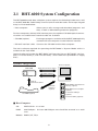
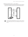
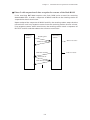
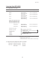
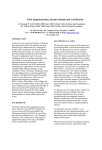
2.1 BHT-6000 System Configuration
The BHT-6000 barcode data collection system requires the following hardware as well
as the BHT-6000 Bar Code Handy Terminal (which reads bar codes and accepts keypad
entry) as illustrated below:
• Host computer:
Allows you to edit, manage and download programs and
data, as well as downloading extension programs.
For host computers without IrDA interface ports, the optional CU-6000 optical communications unit and RS-232C interface cable are available.
• CU-6000 (option):
Exchanges programs and data with the BHT-6000 optically
and with the host computer via the RS-232C interface.
• RS-232C interface cable: Connects the CU-6000 and the host computer.
The basic software required for operating the BHT-6000 is "System Mode" which is
resident in the flash ROM.
Optional software includes the BHT-BASIC 3.0 Extension Library, BHT-BASIC 3.0 Compiler, Ir-Transfer Utility C, and Transfer Utility. (Each software is provided in a floppy
disk.)
System Configuration
BHT-6000
Host Computer
Optical Communications
RS-232C Interface
Optical
Communications
RS-232C
Interface
(option)
BHT-BASIC 3.0 Extension
Library (option)
BHT-BASIC 3.0 Compiler
(option)
Ir-Transfer Utility C
(option)
CU-6000 (option)
Transfer Utility (option)
■ Host Computer
OS:
MS-DOS Ver. 3.1 or later
RAM:
640 kilobytes. At least 400-kilobyte area should be reserved as a work
area.
Models: IBM PC/AT, PS/2
8
Chapter 2. Getting Started the BHT-6000 and System Mode
■ CU-6000 and RS-232C Interface Cable (option)
The CU-6000 is an IrDA-compliant communications unit which is required when your
host computer is not equipped with an IrDA interface port. The CU-6000 exchanges
data and programs with the BHT-6000 optically, and with the host computer via the
RS-232C interface cable.
You may directly connect two BHT-6000s with each other by using a commercially
available metal cable having 3-pole mini stereo plugs (as a direct-connect interface
cable). You also connect the BHT-6000 directly with the host computer or with the
modem by using the direct-connect interface cable compatible with the target equipment. (NOTE: The direct-connect interface port of the BHT-6000 is not designed to
stand frequent connecting/disconnecting. You are, therefore, recommended to use
the CU-6000 where you expect to do a lot of connecting and disconnecting of the BHT6000 to/from a host computer.)
■ BHT-BASIC3.0 Extension Library (option)
This Extension Library enables the following functions which cannot be handled by the
ordinary system:
-
Displaying ruled lines on the BHT-6000's LCD
-
Transmitting files by using the X-MODEM and Y-MODEM protocols.
These extension programs are stored in files named xxxx.FN3, in each file per function. You should download a xxxx.FN3 file containing the necessary function to the
BHT-6000 by using Ir-Transfer Utility C or Transfer Utility.
■ BHT-BASIC 3.0 Compiler (option)
This Compiler compiles a source program written in BHT-BASIC 3.0 by an editor of the
host computer running the MS-DOS, into the object program (user program) which
can be used in the BHT-6000. The compiled program file is named "XXX.PD3." (XXX:
File name you can set arbitrarily under the MS-DOS rules) You should download it to
the BHT-6000 by using Ir-Transfer Utility C or Transfer Utility.
■ Ir-Transfer Utility C (option)
Running on the host computer, this utility transfers files between the BHT-6000 and the
host computer. For its file transfer control procedure, the utility uses the BHT-Ir
protocol which complies with the serial IR physical layer standards of IrDA Serial
Infrared Data Link Standard, Version 1.0 (IrDA-SIR 1.0). (For the details about the BHTIr protocol, refer to Chapter 3, Subsection 3.3.2.)
To transfer files under any of the following conditions, use Ir-Transfer Utility C:
-
At transmission speeds of 115200 or 57600 bps (This may be impossible depending upon the host computer type.)
-
When the BHT-6000 is separated from the CU-6000
-
When the BHT-6000 is placed on the CU-6000
-
When transferring via the direct-connect interface of the BHT-6000 (Maximum
transmission speed is 38400 bps.)
9
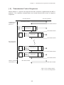
■ Transfer Utility (option)
Running on the host computer, this utility transfers files between the BHT-6000 and the
host computer. It uses the BHT-protocol as a file transfer control procedure. (For the
details about the BHT-protocol, refer to Chapter 3, Subsection 3.3.1.)
To transfer files under any of the following conditions, use Transfer Utility:
-
When the BHT-6000 is placed on the CU-6000
-
Via the direct-connect interface of the BHT-6000
Flash ROM and RAM
A flash ROM and RAM are mounted on the BHT-6000.
The flash ROM stores factory-written System Program and JIS Level 1 & Level 2 fonts.
You can download extension programs, user programs, and user data to either or both
of the flash ROM and RAM.
■ RAM
Programs and data stored in the RAM are backed up by a lithium battery integrated in
the BHT-6000. If the battery voltage level drops below the specified level, the RAM
cannot retain its contents so that the stored files may be damaged.
User programs can write data onto the RAM only.
In System Mode, the RAM is shown as "DRIVE A" or "A:" on the LCD. The names of
those files stored in the RAM are prefixed by "A:."
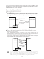
■ Flash ROM
Unlike the RAM, the flash ROM retains the stored programs and data irrespective of
the voltage level of the lithium battery. The flash ROM is limited in the frequency of
rewriting operations; frequent file rewriting exceeding approx. 10,000 times will no
longer allow rewriting. Do not rewrite the flash ROM basically more than one time a
day.
You can write data onto the flash ROM according to any of the following:
•
Downloading a file in System Mode
•
Copying a file from the RAM in System Mode
•
Downloading a file by using XFILE statement in BHT-BASIC 3.0.
You cannot write data scanned with the BHT-6000, onto the flash ROM.
In System Mode, the flash ROM is shown as "DRIVE B" or "B:" on the LCD. The names
of those files stored in the flash ROM are prefixed by "B:."
10
Chapter 2. Getting Started the BHT-6000 and System Mode
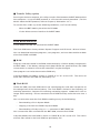
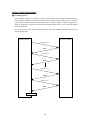
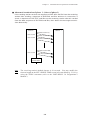
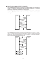
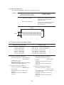
Software Structure
System Program and JIS Level 1 & Level 2 fonts are resident in the system area of the
flash ROM.
To use extension programs and user programs, you should download the program
files into the user area (of the flash ROM or RAM).
Before the execution of user programs, you need to prepare a data file. The data files
will be stored in the user area (of the flash ROM or RAM).
(Flash ROM)
System
Extension
JIS Level 1 &
Programs Level 2 font files programs
(RAM)
User programs
Program
files
Extension
programs
Data files
System Area
User programs
Program
files
Data files
⇔
User Area
Host Computer
■ System Programs
The system programs include the following three sets of programs:
Drivers
Drivers is a set of programs that directly controls the BHT-6000 hardware. It may be
called up by the BHT-BASIC 3.0 Interpreter or System Mode.
BHT-BASIC 3.0 Interpreter
The interpreter interprets and executes instructions in user programs written in BHTBASIC 3.0.
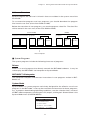
System Mode
System Mode is a system program exclusively designed for the effective use of user
programs in the BHT-6000. It sets up the execution environments for those programs;
e.g., it prepares downloading/uploading conditions, sets the calendar clock, and tests
the BHT-6000 components including the LCD, beeper, and keypad. Shown below is the
System Mode menu (SYSTEM MENU).
SYSTEM MENU
1:EXEC PROGRAM
2:DOWNLOAD
3:UPLOAD
4:SET SYSTEM
5:TEST 6:VER
11
■ JIS Level 1 and Level 2 Font Files
These files contain font data required for displaying Kanji characters on the LCD.
The BHT-6000 has no Kanji ROM, so it stores Kanji fonts in the flash ROM.
The BHT-6000 can display not only the Kanji characters in the conventional standardsize font (16 dots wide by 16 dots high) but also them in the small-size font (12 dots
wide by 12 dots high) in application programs.
■ Extension Programs
These programs extend the system programs by adding new functions which cannot
be handled by the ordinary system.
To download desired extension programs in the BHT-BASIC Extension Library, you
need to use Ir-Transfer Utility C or Transfer Utility.
■ User Programs
You can develop application programs to meet individual job requirements by using
the BHT-BASIC 3.0 Compiler. To download those user programs to the BHT-6000, use
Ir-Transfer Utility C or Transfer Utility.
12
Chapter 2. Getting Started the BHT-6000 and System Mode
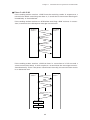
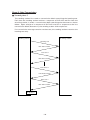
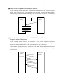
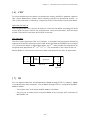
2.2 Infrared Communications
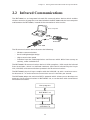
The BHT-6000 has an integrated infrared (IR) communications device which enables
wireless transfer of programs and data between the BHT-6000 and the host computer
and between the BHT-6000s, instead of the conventional wire transfer.
Host computer
BHT-6000
BHT-6000
The IR communications device features the following:
•
Wireless communications
•
Small and lightweight design
•
High transmission speed
•
Freedom from the codes/regulations and licenses which differ from country to
country, unlike radio devices
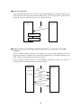
The BHT-6000’s IR communications device is IrDA-compliant. IrDA stands for Infrared
Data Association, which has defined hardware (IrDA Serial Infrared Physical Layer
Link, IrDA-SIR) and communications protocols for IR communications.
The BHT-6000’s physical layer complies with the IrDA-SIR 1.0, with a maximum transfer distance of 1 m and maximum transmission rate of 115.2 kbits per second.
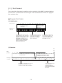
The BHT-6000 adopts the exclusive BHT-Ir protocol which allows you to develop user
programs for IR communications in BHT-BASIC 3.0, as can be done with conventional
wire communications.
User programs
BHT-BASIC 3.0
BHT-Ir protocol
Physical layer
(IrDA-SIR 1.0)
13
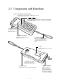
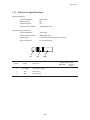
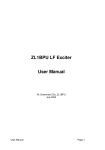
2.3 Components and Functions
• Reading confirmation LED
Illuminates in green when the BHT has successfully read the bar codes.
• M1 and M2 keys
Press either of these keys to start bar-code reading.
(The trigger switch function is assigned to both these
keys by default.)
• Connector cover
Inside this cover is
the direct-connect
interface port.
• Liquid crystal display
(LCD)
Shows the characters and
graphic patterns.
• Hand strap
Put your hand through this
strap to prevent you from
dropping the BHT accidentally.
• Clip
Allows you to clip the BHT on
your pocket.
• Bar-code
reading
window
• Battery cover lock
Use this lock to lock/
unlock the battery cover.
• Battery cover
Remove this cover to replace batteries.
14
• Optical interface
port
This is an infrared
port to exchange
data/programs with
the host computer or
the optical communications unit CU-6000.
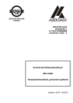
Chapter 2. Getting Started the BHT-6000 and System Mode
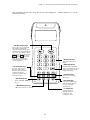
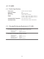
The functions of the keys may be set by user programs. Shown below is a set of
sample functions.
• M1/M2 (magic) keys
These keys are assigned
the trigger switch by
default. Depending upon
definition in System Mode
or in user programs, they
may be used as any of the
ENT key, SF key, and
backlight function on/off
key. They can be also
assigned string data in
user programs.
• F5-F8 Cursor keys
Used to move up to
the preceding line,
down to the next line,
to the preceding
character, and to the
next character.
ABC
DEF
GHI
JKL
MNO
PQR
STU
VWX
Y Z sp
+-*
/$%
• Numerical keys
Used for numerical
input.
• ENT (Enter) key
Finalizes the inputted
data or operations, and
starts the corresponding processing.
• Function keys
Used for choosing
functions.
• PW (Power) key
Turns the BHT-6000 on
or off.
• SF (Shift) key
Used in combination
with numerical keys
for special input
procedures.
• BS (Backspace) key
Moves back one character.
• C (Clear) key
Clears the last
inputted data or
returns to the
original screen.
15
2.4 Preparation
2.4.1 Setting-up 1: Loading Dry Batteries or Battery
Cartridge
Before the first use of the BHT-6000, be sure to load dry batteries or battery cartridge
as shown below. Dry batteries or battery cartridge is not loaded in the BHT-6000 when
shipped from the factory.
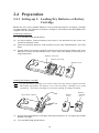
Loading dry batteries
(1)
Turn the BHT-6000 upside down.
(2)
As shown below, slide the battery cover lock in the direction of the arrow and
remove the battery cover.
(3)
Check the polarity (positive and negative) of two new LR03 batteries and load
them.
(4)
Put the battery cover back into place taking care not to pinch the battery pull strap
between its cover and the bottom cover. Then, return the battery cover lock to its
original position.
Battery cover lock
Battery pull strap
Battery cover
+
-
+
-
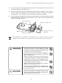
Loading the battery cartridge
NOTE
To use the battery cartridge, you need to remove the dry battery support from the
BHT-6000 and replace the battery cover with the battery cartridge cover (sold
separately). The battery cartridge cover has an opening for charge terminals.
Battery
cover
Dry battery support
Battery
cartridge
cover
(1)
Charge the Ni-MH battery cartridge, referring to Section 5.5, “Charging the Ni-MH
Battery Cartridge.”
(2)
Turn the BHT-6000 upside down.
16
Chapter 2. Getting Started the BHT-6000 and System Mode
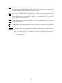
(3)
As shown below, slide the battery cover lock in the direction of the arrow and
remove the battery cartridge cover.
(4)
Check the polarity (positive and negative) of the battery cartridge. Then, load it so
that the end of the battery pull strap appears above the battery cartridge as
shown below. This facilitates easy removal of the battery cartridge.
(5)
Put the battery cartridge cover back into place taking care not to pinch the battery
pull strap between its cover and the bottom cover. Then, return the battery cover
lock to its original position.
Battery pull strap
Battery cartridge cover
Opening for charge
terminals
Battery cover lock
Battery cartridge
NOTE
The Ni-MH battery cartridge is sold either in a set with its cover or by itself.
Purchase the set with the cover if this is the first time the battery is being used.
WARNING
• Never disassemble or heat the battery cartridge,
nor put it into fire or water; doing so could
cause battery-rupture or leakage of battery fluid,
resulting in a fire or bodily injury.
• Do not carry or store the battery cartridge together with metallic ball-point pens, necklaces,
coins, hairpins, etc.
Doing so could short-circuit the terminal pins,
causing the batteries to rupture or the battery
fluid to leak, resulting in a fire or bodily injury.
• Avoid dropping the battery cartridge or letting
it undergo any shock or impact.
Doing so could cause the batteries to break,
generate heat, rupture or burn.
• Never charge the Ni-MH battery cartridge where
any inflammable gases may be emitted; doing
so could cause fire.
CAUTION
• Do not use batteries or power sources other
than the specified ones; doing so could generate heat or cause malfunction.
17
NOTE
When you first load batteries (or battery cartridge) after purchase or you load them
(it) after leaving the BHT-6000 unused for a long time, do not remove the batteries
(battery cartridge) within 24 hours after that loading.
NOTE
Do not leave the BHT-6000 with no batteries or battery cartridge loaded for a long
time. Doing so may cause loss of memory contents as well as a system error while
showing the message "System error! Contact your administrator. Note the error
drive. (DRIVE X)" on the LCD.
NOTE
When disposing of the battery cartridge, cover the terminal pins with vinyl tape to
prevent short-circuit.
NOTE
An early upload of gathered data is recommended, since the data stored in the RAM
might be affected by the so-called "soft error" or other environmental phenomena.
REFERENCE
The BHT-6000 has an integrated rechargeable lithium battery which backs up
the memory in the BHT-6000 when no batteries or battery cartridge is loaded
or the voltage level of the batteries or battery cartridge drops below the
specified level. The lithium battery is automatically charged by the batteries
or battery cartridge.
18
Chapter 2. Getting Started the BHT-6000 and System Mode
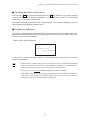
■ Checking the Battery Voltage Level
Pressing the ENT key while holding down the SF key displays the current voltage
level of the batteries or battery cartridge as a bar indicator on the LCD. (Releasing
those keys will erase the indication.)
For details, refer to Subsection 2.4.3, "Adjusting the LCD Contrast & Beeper Volume,
and Displaying the Battery Voltage Level."
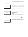
■ Low Battery Indication
If the battery voltage level drops below the specified level while the BHT-6000 is in
operation, the BHT-6000 displays the following message on the LCD, beeps five times,
and turns itself off automatically.
• When driven by dry batteries
Replace the
batteries!
If either of the above messages appears, immediately turn the power off and then
replace the batteries.
NOTE
• Before battery replacement, be sure to turn the power off. Within three minutes
from the removal of batteries, you should load new batteries to avoid data loss.
After replacement, turn the power on and check the operation.
• Be sure to put in two new alkaline manganese batteries (LR03).
• If the BHT-6000 is not to be used for one month or more, remove the batteries.
Upload the data stored in the BHT-6000 memory to the host computer if
necessary; otherwise, the stored data will be lost.
19
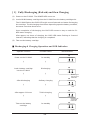
• When driven by the Ni-MH battery cartridge
Charge the
battery!
If either of the above messages appears, immediately turn the power off, and then
charge the Ni-MH battery cartridge or replace it with a fully charged one.
You may charge the Ni-MH battery cartridge with the optional CU-6001 communications unit or C-600 quick charger. For the charging procedure using the CU-6001, refer
to Chapter 5. For that using the C-600, refer to the "C-600 User’s Manual."
WARNING
Only use the dedicated charger (CU-6001 or
C-600) for charging the Ni-MH battery cartridge.
CAUTION
Never charge a wet or damp Ni-MH battery cartridge.
Doing so could cause the batteries to break, generate heat, rupture or burn.
20
Chapter 2. Getting Started the BHT-6000 and System Mode
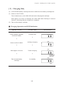
2.4.2 Setting-up 2: Initializing the BHT-6000 and
Setting the Calendar Clock
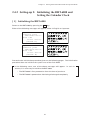
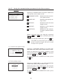
[ 1 ] Initializing the BHT-6000
Power on the BHT-6000 by pressing the PW key.
Either of the following messages will appear, either in English or Japanese.
System error!
Contact your
administrator.
Note the
error drive.
(DRIVE A)
System error!
Contact your
administrator.
Note the
error drive.
(DRIVE B)
Proceed to the initialization procedure given on the following pages. The initialization
procedure does not initialize the system area of the flash ROM.
In the following cases, one of the above messages will appear. In such instances, it is necessary to initialize the BHT-6000.
• The BHT-6000 is first powered on from the time of purchase.
• The BHT-6000 is powered on after being discharged completely.
21
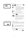
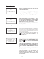
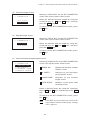
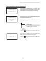
(1)
Selecting the memory area to be initialized
INITIALIZE
1:ALL
2:DRIVE A
3:DRIVE B
Press the PW key while holding down the SF ,
M1 and 0 keys together.
The screen shown at left will appear.
1 ALL
: Initializes both the flash ROM (except for its system area) and RAM.
This should be chosen when you
first power on the BHT-6000 from
the time of purchase.
2 DRIVE A : Initializes the RAM only.
3 DRIVE B : Initializes the flash ROM only (except for its system area).
Select a desired item by using the numerical keys,
then press the ENT key.
REFERENCE
If the message "System error! Contact
your administrator. Note the error drive.
(DRIVE A)" appears on the LCD, select
"2: DRIVE A" to initialize the RAM.
If the message "System error! .....
(DRIVE B)" appears, select "3: DRIVE
B" to initialize the flash ROM.
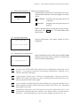
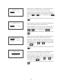
(2)
Confirming the memory area selected for initialization
INITIALIZE
(ALL)
OK ?
1:Yes 2:No
Selecting the memory area in step (1) above will
call up the confirmation screen shown at left where
you check the selected memory area on the 2nd
line.
1 Yes : Shifts to the message version selection
screen before executing initialization.
2 No : Cancels initialization and turns the power
off.
Select a desired item by using the numerical keys,
then press the ENT key.
To return to the previous screen, press the C key.
22
Chapter 2. Getting Started the BHT-6000 and System Mode
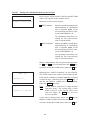
(3)
Selecting the English or Japanese message version
SELECT MESSAGE
1:JAPANESE
2:ENGLISH
Preceding the execution of initialization, the message version selection screen will appear as shown
at left.
1 JAPANESE : Switches the message version to
Japanese.
2 ENGLISH
: Switches the message version to
English.
Select a desired item by using the numerical keys,
then press the ENT key. The BHT-6000 starts
initialization.
(4)
During initialization
INITIALIZE
During initialization, the screen shown at left is
displayed.
**Initializing**
(5)
Completion of initialization
INITIALIZE
Upon completion of the initialization, the BHT-6000
displays the screen shown at left for a second and
turns itself off automatically.
** Completed **
NOTE
Do not power off the BHT-6000 until the above initialization completion screen
appears. A too-early powering-off will interrupt initialization, requiring you to
initialize the BHT-6000 again.
NOTE
If the message "System error! Contact your administrator. Note the error drive.
(DRIVE X)" appears as shown on page 20 although the initialization has completed, initialize the BHT-6000 again.
NOTE
If you initialize the BHT-6000 after downloading user programs and data, all of
those programs and data stored in the target memory area will be lost. Download
them again if necessary.
NOTE
Initialization will restore the LCD contrast level (refer to Subsection 2.4.3), communications conditions and other settings to the default values, so modify them if
necessary. After initialization, be sure to set the calendar clock (refer to [ 2 ]).
23
[ 2 ] Setting the Calendar Clock (date and time)
SYSTEM MENU
1:EXEC PROGRAM
2:DOWNLOAD
3:UPLOAD
4:SET SYSTEM
5:TEST 6:VER
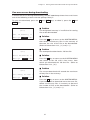
(1)
While holding down the SF and 1 keys,
press the PW key to start System Mode. The
SYSTEM MENU shown at left will appear.
SET SYSTEM
1:PROGRAM 6:COM
2:DISPLAY 7:KEY
3:DATE/TIME
4:BARCODE
5:RESUME
(2)
Press the 4 key to select the "SET SYSTEM"
on the SYSTEM MENU and then press the
ENT key, and the screen shown at left will
appear.
SET DATE/TIME
(3)
Press the 3 key on the SET SYSTEM screen
to select the "DATE/TIME" and then press the
ENT key, and the screen shown at left will
appear.
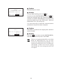
(4)
Use the numerical keys to enter the year (only
the last two digits), month, day, hour, and
minute in this order. If the data is in one
digit, add a 0 (zero) preceding the data.
(To return to the immediately preceding
screen during this setting procedure, press
the C key.)
00/01/01 00:00
_ /
/
:
NOTE
For the year, be sure to enter the last two
digits of the year. For the hour, enter it
in the 24-hour format.
If any of the year, month, day, hour, and
minute is not entered, the ENT key
does not become operable.
If you make a wrong entry, press the BS key
to delete it and then enter the correct data.
24
Chapter 2. Getting Started the BHT-6000 and System Mode
[Example] To set 1997, August 19, at 4:00
p.m.
SET DATE/TIME
00/01/01 00:00
Press 9 , 7 , 0 , 8 , 1 , 9 , 1 , 6 , 0 , and
0 .
97/08/19 16:00_
SET DATE/TIME
(5)
Press the
setting.
ENT
key to register the above
(6)
Press the C key to return to the SET SYSTEM
screen.
97/08/19 16:00
_ /
/
:
25
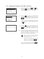
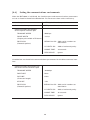
[ 3 ] Deleting the JIS Font Files
The JIS Level 1 and Level 2 font files, which are resident in the flash ROM, contain font
data for displaying Kanji characters on the LCD. If you do not need to display Kanji
characters, you can delete those JIS font files according to the steps below. After
deletion, the memory area which was occupied by those files can be used as a user
area.
SYSTEM MENU
1:EXEC PROGRAM
2:DOWNLOAD
3:UPLOAD
4:SET SYSTEM
5:TEST 6:VER
(1)
While holding down the SF and 1 keys,
press the PW key to start up System Mode.
The SYSTEM MENU screen shown at left will
appear.
(2)
Press the 2 key while holding down the SF
key.
JIS font menu
The JIS 1/JIS 2 menu shown at left will appear.
JIS 1/JIS 2
1:DELETE
2:DOWNLOAD
3:UPLOAD
(To return to the previous screen, press the
C key.)
(3)
If the "1: DELETE" has not been selected, press
the 1 key. Then, press the ENT key.
Deletion menu
The screen shown at left will appear.
DELETE
(To return to the previous screen, press the
C key.)
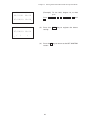
1:JIS 1
2:JIS 2
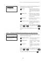
(4)
Press the 1 key to delete the JIS Level 1 font
file. (To delete the JIS Level 2 font file, press
the 2 key.)
Confirmation screen
The confirmation screen will appear.
DELETE
JIS 1 DELETE
OK ?
(5)
Press the 1 key and then press the ENT key.
1:Yes 2:No
Deletion completion screen
DELETE
JIS 1 DELETE
The selected font file (the JIS Level 1 font file
in this example) will be deleted and the screen
shown at left will appear.
** Completed **
26
Chapter 2. Getting Started the BHT-6000 and System Mode
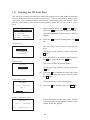
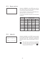
2.4.3 Adjusting the LCD Contrast & Beeper Volume,
and Displaying the Battery Voltage Level
[ 1 ] Adjusting the LCD Contrast & Beeper Volume
While holding down the M1 key, press the PW key, and the following screen will
appear on the LCD. This screen will disappear if no keys are pressed for five seconds.
LCD CONTRAST
BEEPER VOLUME
(The current selection is reverse-displayed.)
Adjusting the LCD contrast
You can adjust the LCD brightness to eight contrast levels.
1) Use the F5 and F6 keys to select the LCD CONTRAST line.
2) To decrease the contrast, press the F7 key; to increase it, press the F8 key.
Adjusting the beeper volume
You can adjust the beeper volume to four levels from OFF to MAX.
1) Use the F5 and F6 keys to select the BEEPER VOLUME line.
2) To turn down the volume, press the F7 key; to turn it up, press the F8 key.
After making the above setting, either press the ENT key or press no key for five
seconds, and the new setting will be fixed and the above screen will disappear.
27
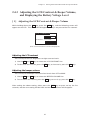
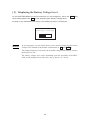
[ 2 ] Displaying the Battery Voltage Level
On the SYSTEM MENU or during execution of user programs, press the ENT key
while holding down the SF key for displaying the battery voltage level.
As long as you hold down those keys, the following screen is displayed.
Battery Voltage
REFERENCE
In user programs, you can select the key to be used for displaying the battery
voltage level (instead of the default: combination of SF and ENT ).
The displayed battery level shows the terminal voltage of the battery, not how
much power is left.
The battery voltage level varies depending upon the operation of the BHT6000, so the displayed level also may vary by about 1 to 2 levels.
28
Chapter 2. Getting Started the BHT-6000 and System Mode
2.5 Operating in System Mode
System Mode is an operating software exclusively designed for the effective use of the
BHT-6000, which includes various functions as shown on the following pages.
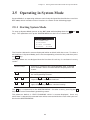
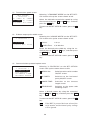
2.5.1 Starting System Mode
To start up System Mode, power on the BHT-6000 while holding down the SF and 1
keys. This operation calls up the SYSTEM MENU on the LCD as shown below.
SYSTEM MENU
1:EXEC PROGRAM
2:DOWNLOAD
3:UPLOAD
4:SET SYSTEM
5:TEST 6:VER
The function selected is reverse-displayed (white-on-black) with the cursor. To select a
desired item in System Mode, press the corresponding numerical key and then press
the ENT key.
The keys below are so designed that the function of each key is consistent in every
screen.
Numerical keys
Pressing a numerical key corresponding with a desired
menu number selects the desired item displayed on the
screen.
ENT key
Pressing this key registers the selected item and executes
the corresponding function.
F5 and F6 keys
Pressing F5 and F6 moves the cursor up and down,
respectively, to select a desired item.
F7 and F8 keys
Pressing F7 and F8 moves the cursor to the left and
right, respectively, to select a desired setting.
The C key is inoperative on the SYSTEM MENU. On other screens, pressing the C
key returns to the immediately preceding screen.
The power-on default is "EXEC PROGRAM" which is reverse-displayed. Once any
other item is selected, the selected item will be reversed with the cursor when you turn
back to the SYSTEM MENU.
29
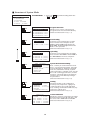
■ Structure of System Mode
SYSTEM MENU
1:EXEC PROGRAM
2:DOWNLOAD
3:UPLOAD
4:SET SYSTEM
5:TEST 6:VER
1 and
ENT
SYSTEM MENU ⇐ Press the PW key while holding down the
SF and 1 keys.
EXECUTE PROGRAM
A:SAMPLE01.PD3
A:SAMPLE02.PD3
A:SAMPLE03.PD3
A:SAMPLE04.PD3
B:SAMPLE05.PD3
Program Execution
Allows you to select a desired user
program to be executed immediately.
(Refer to Subsection 2.5.3, [ 1 ].)
Downloading
Transfers user program files or data
files from the host computer to the
RAM or flash ROM integrated in the
BHT-6000. Downloading between the
BHTs is also possible.
(Refer to Subsection 2.5.3, [ 2 ].)
2 and
ENT
DOWNLOAD
1:DRIVE A
2:DRIVE B
3:HT<->HT COPY
3 and
ENT
UPLOAD
1:DRIVE A
2:DRIVE B
3:DRIVE A (ALL)
4:DRIVE B (ALL)
5:HT<->HT COPY
4 and
ENT
SET SYSTEM
1:PROGRAM 6:COM
2:DISPLAY 7:KEY
3:DATE/TIME
4:BARCODE
5:RESUME
System Environment Setting
Sets a variety of environmental conditions—an execution program, message
version (English or Japanese), display
font size (standard or small), system
status indication, calendar clock, special
bar-code scanning parameters, resume
function, communications parameters,
interface port, and shift-key & magickey functions.
(Refer to Subsection 2.5.3, [ 4 ].)
5 and
ENT
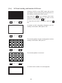
TEST
1:BARCODE 6:LCD
2:MEMORY 7:KEY
3:BEEPER 8:FILE
4:AGING
5:COMMUNICATION
Testing
Used for the bar-code reading test,
memory test, beeper test, aging test,
communications test, LCD indication
test, reading confirmation LED test, keyentry test, and file test.
(Refer to Subsection 2.5.3, [ 5 ].)
6 and
ENT
VERSION
SYSTEM
: x.xx
JIS1 FONT: x.xx
JIS2 FONT: x.xx
RAM SIZE : xxxKB
ROM SIZE : xxxKB
C
30
Uploading
Transfers user program files and data
files stored in the RAM or flash ROM of
the BHT-6000 to the host computer.
(Refer to Subsection 2.5.3, [ 3 ].)
Version Indication
Shows the versions of memory-resident
System Program and JIS font files, and
the sizes of the RAM and flash ROM.
(Refer to Subsection 2.5.3, [ 6 ].)
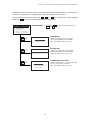
Chapter 2. Getting Started the BHT-6000 and System Mode
In addition to the functions given on the previous page, System Mode has these three
functions: Deleting files, Copying files, and Handling the JIS font files.
To call up these functions, press the 0 , 1 , or 2 key, respectively, while holding
down the SF key when the SYSTEM MENU is displayed.
SYSTEM MENU
1:EXEC PROGRAM
2:DOWNLOAD
3:UPLOAD
4:SET SYSTEM
5:TEST 6:VER
0 with
SF held
down
1 with
SF held
down
2 with
SF held
down
SYSTEM MENU ⇐ Press the PW key while holding down the
SF and 1 keys.
DELETE
1:DRIVE A
2:DRIVE B
COPY
1:DRIVE A --> B
2:DRIVE B --> A
JIS 1/JIS 2
1:DELETE
2:DOWNLOAD
3:UPLOAD
31
Deleting Files
Deletes a program file or data file
stored in the RAM or flash ROM.
(Refer to Subsection 2.5.3, [ 7 ].)
Copying Files
Copies a program file or data file
between the RAM and flash ROM.
(Refer to Subsection 2.5.3, [ 8 ].)
Handling the JIS Font Files
Deletes, downloads, or uploads the JIS
Level 1 and Level 2 font files.
(Refer to Subsection 2.5.3, [ 9 ].)
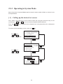
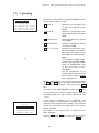
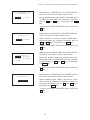
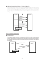
2.5.2 Operating in System Mode
Some functions in System Mode require several screens to be shifted, as shown in the
example below.
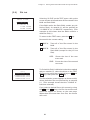
[ 1 ] Calling up the desired set screen
First, select a desired item on the current screen by using the numerical key or the
cursor keys ( F5 and F6 ) so as to reverse-display the desired item.
Press the ENT key to establish the selected item and proceed to the subsequent
screen.
To return to the preceding screen, press the C key.
Press 4 or use
F5 and F6 to
select "SET SYSTEM."
SYSTEM MENU
1:EXEC PROGRAM
2:DOWNLOAD
3:UPLOAD
4:SET SYSTEM
5:TEST 6:VER
ENT
Press 2 or use
F5 and F6 to
select "DISPLAY."
SET SYSTEM
1:PROGRAM 6:COM
2:DISPLAY 7:KEY
3:DATE/TIME
4:BARCODE
5:RESUME
C
ENT
SET DISPLAY
1:MESSAGE
Japanese
English
2:FONT 8dot 6dot
3:STATUS ON OFF
32
C
Chapter 2. Getting Started the BHT-6000 and System Mode
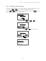
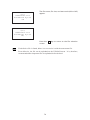
[ 2 ] Selecting a desired setting
First, select a desired item on the current screen by using the numerical key or the
cursor keys ( F5 and F6 ) so as to reverse-display the desired item.
Use the F7 and F8 keys to select a desired setting and then press the ENT key. The
screen returns to the original selection screen.
SET DISPLAY
1:MESSAGE
Japanese
English
2:FONT 8dot 6dot
3:STATUS ON OFF
Press 2 or use F5 and F6 to select
the desired set item.
SET DISPLAY
1:MESSAGE
Japanese
English
2:FONT 8dot 6dot
3:STATUS ON OFF
Use F7 and F8 to select the desired
setting.
SET DISPLAY
1:MESSAGE
Japanese
English
2:FONT 8dot 6dot
3:STATUS ON OFF
ENT
SET SYSTEM
1:PROGRAM 6:COM
2:DISPLAY 7:KEY
3:DATE/TIME
4:BARCODE
5:RESUME
33
2.5.3 Detailed Description of the Functions in System
Mode
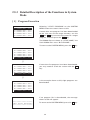
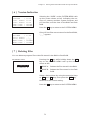
[ 1 ] Program Execution
EXECUTE PROGRAM
A:SAMPLE01.PD3
A:SAMPLE02.PD3
A:SAMPLE03.PD3
A:SAMPLE04.PD3
B:SAMPLE05.PD3
Selecting "1:EXEC PROGRAM" on the SYSTEM
MENU shows the screen shown at left.
If more than one program has been downloaded
to the user area of the target memory, use the
F5 and F6 keys to move the cursor to a target
program, and then press the ENT key.
The RAMed files are shown as "A:FILE NAME;" the
flash-ROMed files are as "B:FILE NAME."
To return to the SYSTEM MENU, press the C key.
EXECUTE PROGRAM
A:SAMPLE01.PD3
A:SAMPLE02.PD3
A:SAMPLE03.PD3
A:SAMPLE04.PD3
B:SAMPLE05.PD3
⇓
EXECUTE PROGRAM
A:SAMPLE02.PD3
A:SAMPLE03.PD3
A:SAMPLE04.PD3
B:SAMPLE05.PD3
B:SAMPLE06.PD3
If more than five programs have been downloaded,
you may need to scroll the screen with the F6
key.
⇓
EXECUTE PROGRAM
A:SAMPLE04.PD3
B:SAMPLE05.PD3
B:SAMPLE06.PD3
B:SAMPLE07.PD3
B:SAMPLE08.PD3
In the example shown at left, eight programs are
downloaded.
EXECUTE PROGRAM
If no program file is downloaded, the message
shown at left will appear.
****************
*NO FILE EXISTS*
****************
To return to the SYSTEM MENU, press the C key.
34
Chapter 2. Getting Started the BHT-6000 and System Mode
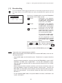
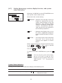
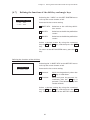
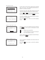
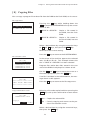
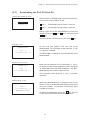
[ 2 ] Downloading
NOTE
If you download a file having the same name as one already used in the user area of
the target memory in the BHT-6000, the newly downloaded file replaces the old
one.
DOWNLOAD
1:DRIVE A
2:DRIVE B
3:HT<->HT COPY
Selecting "2: DOWNLOAD" on the SYSTEM MENU
calls up the screen shown at left.
1 DRIVE A
: Downloads a user program
file (object file compiled by
the BHT-BASIC 3.0 Compiler)
or data file to the RAM.
2 DRIVE B
: Downloads a user program
file (object file compiled by
the BHT-BASIC 3.0 Compiler)
or data file to the flash ROM.
3 HT<->HT COPY : Downloads all of the files,
system parameters, and calendar clock data stored in
the connected BHT-6000.
This function enables copying between the BHT-6000s.
For the preparation to be
made preceding the start of
this function, refer to NOTE
below.
Select a desired item by using the numerical keys
or F5 and F6 keys, and the selected item
becomes reverse-displayed. Then press the ENT
key.
To return to the SYSTEM MENU, press the C key.
NOTE
Preparation for Copying between the BHTs
Before downloading to the BHT-6000 from another BHT-6000, make the following preparation:
• At each BHT-6000, set the interface port. The default is an optical interface
(OPT).
Interface setting procedure: Starting on the SYSTEM MENU, select "4:SET
SYSTEM," "6:COM," and "3:COM PORT." On the SET COM PORT screen,
select the optical interface (OPT) or direct-connect interface (IFC) of "2:SYSTEM MODE."
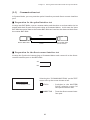
• When using the direct-connect interface, pull out the connector cover on
each BHT-6000 to expose the direct-connect interface port. Connect the
BHT-6000s via those ports with the direct-connect interface cable (having 3pole mini stereo plugs). For the details about the cable, refer to Chapter 3,
Section 3.1.
• On the uploading BHT-6000, run System Mode and select "3:UPLOAD" and
"5:HT<->HT COPY."
35
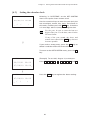
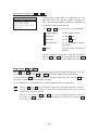
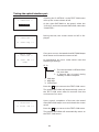
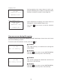
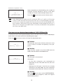
Download screens
DOWNLOAD FILE
(A:)
** Waiting **
⇓
DOWNLOAD FILE
(A:)
** Loading **
With this screen displayed, the BHT-6000 waits for
a file to be downloaded.
In the center of the 2nd line appears the selected
downloading type--(A:), (B:), or (HT<->HT) indicating the downloading to the RAM, to the flash ROM,
or copying between the BHTs, respectively. The
screen at left shows that "1: DRIVE A" has been
selected.
Upon start of optional Ir-Transfer Utility C, Transfer Utility or equivalent program (upon receipt of
an ENQ code from the host computer), the BHT6000 displays the screen shown at left.
(Refer to the "Ir-Transfer Utility C Guide" or "Transfer Utility Guide.")
⇓
DOWNLOAD FILE
(A:)
SAMPLE00.PD3
** Loading **
XXXXX/YYYYY
⇓
DOWNLOAD FILE
(A:)
SAMPLE00.PD3
** Completed **
YYYYY/YYYYY
While the downloading operation is in progress,
the screen shown at left is displayed indicating the
file name and the number of received records/the
total number of records.
To abort the downloading operation, press the
C key. The screen will switch back to the
DOWNLOAD menu.
Upon completion of downloading, the number of
received records becomes equal to the total
number of records and the beeper beeps once.
Press the C key to return to the DOWNLOAD
menu.
If the host computer downloads another new file
(if the BHT-6000 receives an ENQ code) when this
screen is displayed, the BHT-6000 starts receiving
it.
(Refer to the "Ir-Transfer Utility C Guide" or "Transfer Utility Guide.")
If you have selected "3: HT<->HT COPY" on the
DOWNLOAD menu, a sequence of the above
screens will be repeated by the number of files to
be downloaded.
36
Chapter 2. Getting Started the BHT-6000 and System Mode
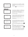
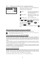
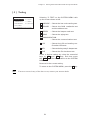
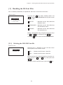
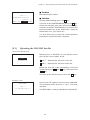
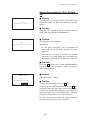
If an error occurs during downloading
If some error occurs during downloading, the BHT-6000 beeps three times and shows
one of the following screens with the prompt "Retry?":
To retry the download, press the 1 and ENT keys; to abort it, press the 2 and
ENT keys.
DOWNLOAD FILE
(A:)
Out of memory !!
Retry? 1:Yes2:No
■ Problem
The designated memory is insufficient for storing
files to be downloaded.
■ Solution
Press the 2 key to return to the SYSTEM MENU,
then delete unnecessary files in the memory or
decrease the size of the file to be downloaded.
(Refer to Subsection 2.5.3, [ 7 ] and [ 2 ].)
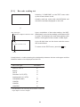
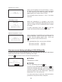
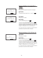
DOWNLOAD FILE
(A:)
■ Problem
File mismatch !!
■ Solution
Retry? 1:Yes2:No
Press the 2 key to return to the SYSTEM MENU
and switch to the JIS 1/JIS 2 font menu, from
which you download the JIS font file. (Refer to
Subsection 2.5.3, [ 9 ].)
DOWNLOAD FILE
(A:)
Too many files!!
Retry? 1:Yes2:No
You attempted to download a JIS font file.
■ Problem
The current download will exceed the maximum
of forty files in the memory.
■ Solution
Press the 2 key to return to the SYSTEM MENU.
If you attempted to download more than one file,
delete unnecessary files in memory or decrease
the number of files to be downloaded. (Refer to
Subsection 2.5.3, [ 7 ] and [ 2 ].)
37
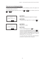
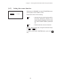
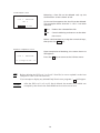
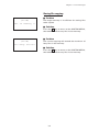
DOWNLOAD FILE
(A:)
XXXXXXXX.XXX
Communication
error !!
Retry? 1:Yes2:No
■ Problem
Downloading has failed.
■ Solution
To retry downloading, press the 1 key.
To return to the SYSTEM MENU, press the 2 key.
Check the interface port and communications parameters in the SET SYSTEM menu or perform the
communications test in the TEST menu. (Refer to
Subsection 2.5.3, [4.6] and [5.5].)
It is also necessary to check the communications
parameters setup of the host computer.
DOWNLOAD FILE
(B:)
Drive A memory
short !!
Retry? 1:Yes2:No
■ Problem
The RAM is insufficient for copying files stored in
the flash ROM.
■ Solution
Press the 2 key to return to the SYSTEM MENU,
then delete unnecessary files in the RAM.
NOTE
When receiving downloaded files to the flash
ROM, the BHT-6000 may copy the files
stored in the flash ROM into the RAM. This
requires an unused user area of 128 kilobytes
in the RAM. If there is no area for copying
in the RAM, the error message shown at left
will appear.
38
Chapter 2. Getting Started the BHT-6000 and System Mode
[ 3 ] Uploading
UPLOAD
1:DRIVE A
2:DRIVE B
3:DRIVE A (ALL)
4:DRIVE B (ALL)
5:HT<->HT COPY
⇓
Selecting "3: UPLOAD" on the SYSTEM MENU calls
up the screen shown at left.
1 DRIVE A
: Uploads a user program file
or data file stored in the
RAM.
2 DRIVE B
: Uploads a user program file
or data file stored in the flash
ROM.
3 DRIVE A (ALL)
: Uploads all of the files stored
in the RAM.
4 DRIVE B (ALL)
: Uploads all of the files stored
in the flash ROM.
5 HT<->HT COPY : Uploads all of the files, system parameters, and calendar clock data stored in the
BHT-6000, to another BHT6000.
This function enables copying between the BHT-6000s.
At the receiving BHT-6000,
select "2: DOWNLOAD" and
"3: HT<->HT COPY" in System Mode.
For the preparation to be
made preceding the start of
this function, refer to NOTE
given on page 34.
Select a desired item by using the numerical keys
or F5 and F6 keys, and the selected item becomes reverse-displayed. Then press the ENT
key.
To return to the SYSTEM MENU, press the C key.
In the center of the 2nd line appears the selected
uploading type--(A:), (B:), (A:ALL), (B:ALL) or (HT
<->HT).
UPLOAD FILE
(A:)
SAMPLE01.PD3
SAMPLE02.PD3
SAMPLE03.PD3
SAMPLE04.PD3
If you select "1: DRIVE A" or "2: DRIVE B," the
screen shown at left will appear, showing all of the
program files and data files stored in the selected
memory. If you select any other items, this screen
will be skipped.
The screen at left shows that "1: DRIVE A" has
been selected.
Use the F5 and F6 keys to move the cursor to
the file to be uploaded, then press the ENT key.
39
UPLOAD FILE
(A:)
****************
*NO FILE EXISTS*
****************
If you select any of the "1:DRIVE A" through
"4:DRIVE B (ALL)" when no data files are stored in
the specified memory, the message shown at left
will appear.
Pressing the C key returns to the UPLOAD menu.
Upload screens
UPLOAD FILE
(A:)
** Waiting **
If you select the "1:DRIVE A" or "2:DRIVE B" and
choose a file to be uploaded or if you select any of
the "3:DRIVE A (ALL)" through "5:HT<->HT COPY,"
then the screen shown at left will appear.
Showing this screen, the BHT-6000 waits for a
file(s) to be uploaded.
⇓
UPLOAD FILE
(A:)
** Loading **
⇓
UPLOAD FILE
(A:)
SAMPLE00.PD3
** Loading **
XXXXX/YYYYY
⇓
UPLOAD FILE
(A:)
SAMPLE00.PD3
** Completed **
YYYYY/YYYYY
Upon start of optional Ir-Transfer Utility C, Transfer Utility or equivalent program (upon receipt of
an ACK code from the host computer), the BHT6000 displays the screen shown at left.
(Refer to the "Ir-Transfer Utility C Guide" or "Transfer Utility Guide.")
While the uploading operation is in progress, the
screen shown at left is displayed indicating the file
name and the number of sent records/the total
number of records.
To abort the uploading operation, press the C
key. The screen will switch back to the UPLOAD
menu.
Upon completion of uploading, the number of sent
records becomes equal to the total number of
records and the beeper beeps once. Press the C
key to return to the UPLOAD menu.
If you have selected "3: DRIVE A (ALL)," "4: DRIVE
B (ALL)," or "5: HT<->HT COPY" on the UPLOAD
menu, a sequence of the above screens will be
repeated by the number of files to be uploaded.
40
Chapter 2. Getting Started the BHT-6000 and System Mode
If an error occurs during uploading
If some error occurs during uploading, one of the following screens will appear and
the beeper beeps three times.
To retry the uploading operation, press the 1 and ENT keys; to abort it, press the
2 and ENT keys.
UPLOAD FILE
(A:)
SAMPLE00.PD3
File error !!
■ Problem
The file you attempted to upload is damaged.
■ Solution
Upload?1:Yes2:No
To upload the damaged file as is, press the 1 key.
UPLOAD FILE
(A:)
XXXXXXXX.XXX
Communication
error !!
Retry? 1:Yes2:No
■ Problem
Uploading has failed.
■ Solution
To retry uploading, press the 1 key.
To return to the SYSTEM MENU, press the 2 key.
Check the interface port and communications parameters in the SET SYSTEM menu or perform the
communications test in the TEST menu. (Refer to
Subsection 2.5.3, [4.6] and [5.5].)
It is also necessary to check the communications
parameters setup of the host computer.
41
[ 4 ] System Environment Setting
SET SYSTEM
1:PROGRAM 6:COM
2:DISPLAY 7:KEY
3:DATE/TIME
4:BARCODE
5:RESUME
Selecting "4: SET SYSTEM" on the SYSTEM MENU
calls up the screen shown at left.
1 PROGRAM
: Sets an execution program
to be run when the power
is turned on.
2 DISPLAY
: Sets the message version
(English or Japanese), display font size (standard or
small), and system status
indication (shift-key icon).
3 DATE/TIME
: Sets the calendar clock
(date and time).
4 BARCODE
: Sets the special bar-code
scanning parameters (the
black-and-white inverted
label reading, the touch
scanning/long-range scanning, and the decoding
level).
5 RESUME
: Sets the resume function.
6 COM
: Sets the communications
environments (interface
port and communications
parameters).
7 KEY
: Defines the functions of the
shift key and magic keys.
Select a desired item by using the numerical keys
or F5 and F6 keys, and the selected item becomes reverse-displayed. Then press the ENT
key.
Press the C key to return to the SYSTEM MENU.
42
Chapter 2. Getting Started the BHT-6000 and System Mode
[4.1]
Setting an execution program
SET EXEC PROGRAM
A:EASYPACK.PD3
A:SAMPLE1.PD3
A:SAMPLE2.PD3
B:SAMPLE3.PD3
B:SAMPLE4.PD3
Selecting "1: PROGRAM" on the SET SYSTEM menu
calls up the screen shown at left.
Reversed is the current setting.
Use the F5 and F6 keys to move the cursor to a
desired execution program to be run when the
power is applied, and then press the ENT key.
To return to the SET SYSTEM menu, press the
C key.
The RAMed files are shown as "A:FILE NAME;" the
flash-ROMed files are as "B:FILE NAME."
SET EXEC PROGRAM
If no files program are stored in the memories, the
screen shown at left will appear.
****************
*NO FILE EXISTS*
****************
To return to the SET SYSTEM menu, press the C
key.
43
[4.2]
Setting the message version, display font size, and system
status indication
SET DISPLAY
1:MESSAGE
Japanese
English
2:FONT 8dot 6dot
3:STATUS ON OFF
Selecting "2: DISPLAY" on the SET SYSTEM menu
calls up the screen shown at left.
Reversed is the current setting.
1 MESSAGE : Switches the message version to
English or Japanese for the indications and messages on the self
diagnosis, LCD contrast, beeper
volume, and battery voltage level
screens. (The default is the message version that you selected in
the initializing sequence.)
2 FONT
: Switches the display font size to
be used in application programs
to the standard (8-dot) or small (6dot).
3 STATUS
: Turns the system status indication
on or off. If it is set to on, the
shift-key icon appears as shown
below.
Select a desired item by using the numerical keys
or the F5 and F6 keys, then select a desired
setting by using the F7 and F8 keys.
Press the ENT key.
To return to the SET SYSTEM menu, press the C
key.
REFERENCE
You may turn the system status indication on or off also by using the OUT
statement in user programs. Refer to the
"BHT-BASIC 3.0 Programmer's
Manual."
System Status Indication
Turning on the system status indication displays the following icon:
Indication
Icon
Shift state of the keys on the keypad
Description
Appears when the keys on the
keypad are shifted.
44
Chapter 2. Getting Started the BHT-6000 and System Mode
[4.3]
Setting the calendar clock
SET DATE/TIME
00/01/01 00:00
_ /
/
:
Selecting "3: DATE/TIME" on the SET SYSTEM
menu calls up the screen shown at left.
Use the numerical keys to enter the year (only the
last two digits), month, day, hour, and minute in
this order, and then press the ENT key. If the data
is in one digit, add a 0 (zero) preceding the data.
NOTE
For the year, be sure to enter the last two
digits of the year. For the hour, enter it in the
24-hour format.
If any of the year, month, day, hour, and
minute is not entered, the ENT key does not
become operable.
⇓
If you make a wrong entry, press the BS key to
delete it and then enter the correct data.
To return to the SET SYSTEM menu, press the C
key.
SET DATE/TIME
00/01/01 00:00
[Example] To set 1997, August 19, at 4:00 p.m.
Press 9 , 7 , 0 , 8 , 1 , 9 , 1 , 6 , 0 , and 0 .
97/08/19 16:00_
⇓
SET DATE/TIME
Press the ENT key to register the above setting.
97/08/19 16:00
_ /
/
:
45
[4.4]
Setting the special bar-code scanning parameters
SET BARCODE
1:INVERT ON OFF
2:TOUCH READ
ON OFF
3:DECODE LEVEL 3
Selecting "4: BARCODE" on the SET SYSTEM menu
calls up the screen shown at left.
Reversed is the current setting.
1 INVERT
: Activates or deactivates the
black-and-white inverted label reading function.
2 TOUCH READ
: Switches to the touch scanning (ON) or long-range
scanning (OFF).
3 DECODE LEVEL : Sets the decode level.
Select a desired item by using the numerical keys
or F5 and F6 keys, and then select a desired
setting by using the F7 and F8 keys.
To increase the decode level, press the F8 key; to
decrease it, press the F7 key.
Press the ENT key.
To return to the SET SYSTEM menu, press the C
key.
Black-and-white inverted label reading function (INVERT)
This function makes it possible to read white bars on a black background.
NOTE
Activating this function might increase the frequency of bar-code reading errors.
This function can usually be set to OFF.
Touch scanning/long-range scanning (TOUCH READ)
You may select touch scanning or long-range scanning. The touch scanning is a
method in which you bring the bar-code reading window to a bar code to be scanned.
The long-range scanning allows you to read bar codes wider than the readable area of
the bar-code reading window by pulling the bar-code reading window away from bar
codes.
If "TOUCH READ" is set to ON, the reading speed increases in touch scanning. In longrange scanning, however, this setting may decrease the reading speed and efficiency
when the ambient illuminance is low or too high.
If "TOUCH READ" is set to OFF, the BHT-6000 can scan bar codes irrespective of the
ambient illuminance. This setting, therefore, is suitable for long-range scanning. Note
that the scanning speed will slightly decrease.
Decode level (DECODE LEVEL)
You may set the recognition level. Decreasing the level value increases the bar-code
reading efficiency, but the BHT-6000 might misread low-quality bar codes (split or
stained). To the contrary, increasing the level value decreases the bar-code reading
efficiency, but it precludes almost all possibilities of misreading.
The setting range of the level value is from 1 to 9 and the default is 3.
46
Chapter 2. Getting Started the BHT-6000 and System Mode
[4.5]
Setting the resume function
SET RESUME
1:ON
2:OFF
Selecting "5: RESUME" on the SET SYSTEM menu
calls up the screen shown at left.
Reversed is the current setting.
1 ON
: Activates the resume function which
resumes whatever display was
shown before the power was turned
off, when the BHT-6000 is powered
up.
2 OFF
: Deactivates the resume function.
Select a desired item by using the numerical keys
or F5 and F6 keys.
To return to the SET SYSTEM menu, press the C
key.
47
[4.6]
Setting the communications environments
After the BHT-6000 is initialized, the interface port and communications parameters
are set as listed in the default table below. Do not access them unless necessary.
Interface port
OPT (Optical interface port)
Communications protocol
BHT-protocol
Defaults
Communications parameters
for the optical interface port
TRANSMIT SPEED
9600 bps
PULSE WIDTH
(Output pulse width of IR beam)
1.63 µs
PROTOCOL
(Protocol options)
SERIAL No. ON: Adds serial numbers to
data blocks.
H. PARITY ON:
Adds a horizontal parity.
LINKUP TIME:
30 seconds
FIELD SPACE:
Ignore
Listed below are the default communications parameters for the direct-connect interface
Defaults
Communications parameters for
the direct-connect interface port
TRANSMIT SPEED
19200 bps
PARITY BIT
None
DATA BIT
(Character length)
8 bits
STOP BIT
1 bit
PROTOCOL
(Protocol options)
SERIAL No. ON: Adds serial numbers to
data blocks.
H. PARITY ON:
Adds a horizontal parity.
LINKUP TIME:
30 seconds
FIELD SPACE:
Ignore
48
Chapter 2. Getting Started the BHT-6000 and System Mode
SET COM
1:OPTICAL
2:CONNECTOR
3:COM PORT
4:PROTOCOL TYPE
Selecting the "6: COM" on the SET SYSTEM menu
calls up the screen shown at left.
1 OPTICAL:
Switches to the communications parameters setting
screen for the optical interface.
2 CONNECTOR:
Switches to the communications parameters setting
screen for the direct-connect interface.
3 COM PORT:
Switches to the interface
port setting screen.
4 PROTOCOL TYPE:
Switches to the communications protocol type setting screen.
Select a desired screen by using the numerical
keys or F5 and F6 keys, and then press the ENT
key.
To return to the SET SYSTEM menu, press the C
key.
[4.6-1]
Setting the communications parameters for the optical interface
SET OPTICAL
1:TRANSMIT SPEED
2:PULSE WIDTH
3:PROTOCOL
Selecting "1:OPTICAL" on the SET COM menu calls
up the screen shown at left.
1 TRANSMIT SPEED:
Switches to the transmission speed screen.
2 PULSE WIDTH:
Switches to the IR beam
output
pulse
width
screen.
3 PROTOCOL:
Switches to the communications protocol option
menu.
Select a desired screen by using the numerical
keys or F5 and F6 keys, and then press the ENT
key.
To return to the SET COM menu, press the C key.
49
(1)
Transmission speed screen
SET SPEED
< OPTICAL >
1: 2400 4: 38400
2: 9600 5: 57600
3:19200 6:115200
Selecting "1:TRANSMIT SPEED" on the SET OPTICAL screen calls up the screen shown at left.
Select the desired transmission speed by using
the numerical keys or F5 and F6 keys, and then
press the ENT key.
To return to the SET OPTICAL screen, press the C
key.
(2)
IR beam output pulse width screen
SET PULSE WIDTH
< OPTICAL >
Selecting the "2:PULSE WIDTH" on the SET OPTICAL screen calls up the screen shown at left.
1:1.63us
2:3/16 Bit Time
1 1.63us:
1.63 µs
2 3/16 Bit Time:
3/16 bit time
Select the desired pulse width by using the numerical keys or F5 and F6 keys, and then press
the ENT key.
To return to the SET OPTICAL screen, press the C
key.
(3)
Communications protocol option menu
SET PROTOCOL
< OPTICAL >
1:SERIAL No.
2:H.PARITY
3:LINKUP TIME
4:FIELD SPACE
Selecting "3: PROTOCOL" on the SET OPTICAL
screen calls up the screen shown at left.
1 SERIAL No.:
Switches to the serial number
ON/OFF screen.
2 H. PARITY:
Switches to the horizontal
parity ON/OFF screen.
3 LINKUP TIME:
Switches to the timeout
length screen.
4 FIELD SPACE:
Switches to the space code
handling screen.
Select a desired screen by using the numerical
keys or F5 and F6 keys, and then press the ENT
key.
To return to the SET OPTICAL screen, press the C
key.
NOTE
If the BHT-Ir protocol has been selected, the
serial number and horizontal parity settings
will be ignored.
50
Chapter 2. Getting Started the BHT-6000 and System Mode
SET SERIAL No.
< OPTICAL >
1:ON
2:OFF
Selecting the "1:SERIAL No." on the SET PROTOCOL menu calls up the screen shown at left.
Select whether or not the system should add serial
numbers to data blocks, by using the numerical
keys or F5 and F6 keys. Then press the ENT
key.
To return to the SET PROTOCOL menu, press the
C key.
SET H.PARITY
< OPTICAL >
1:ON
2:OFF
Selecting the "2:H.PARITY" on the SET PROTOCOL
menu calls up the screen shown at left.
Select whether or not the system should add a
horizontal parity, by using the numerical keys or
F5 and F6 keys. Then press the ENT key.
To return to the SET PROTOCOL menu, press the
C key.
SET LINKUP TIME
< OPTICAL >
1:30 4:120
2:60 5:None
3:90
Selecting the "3:LINKUP TIME" on the SET PROTOCOL menu calls up the screen shown at left.
Select the timeout length (in seconds) to be applied when a link is to be established, by using the
numerical keys or F5 and F6 keys. Then press
the ENT key.
To return to the SET PROTOCOL menu, press the
C key.
SET FIELD SPACE
< OPTICAL >
1:Ignore
2:Data
Selecting the "4:FIELD SPACE" on the SET PROTOCOL menu calls up the screen shown at left.
Select whether space codes in the tail of a data
field should be ignored or handled as data, by
using the numerical keys or F5 and F6 keys.
Then press the ENT key.
To return to the SET PROTOCOL menu, press the
C key.
51
[4.6-2]
Setting the communications parameters for the direct-connect
interface
SET CONNECTOR
1:TRANSMIT SPEED
2:PARITY BIT
3:DATA BIT
4:STOP BIT
5:PROTOCOL
Selecting "2:CONNECTOR" on the SET COM menu
calls up the screen shown at left.
1 TRANSMIT SPEED:
Switches to the transmission speed screen.
2 PARITY BIT:
Switches to the parity setting screen.
3 DATA BIT:
Switches to the character
length screen.
4 STOP BIT:
Switches to the stop bit
length screen.
5 PROTOCOL:
Switches to the communications protocol option
menu.
Select a desired screen by using the numerical
keys or F5 and F6 keys, and then press the
ENT key.
To return to the SET COM menu, press the C key.
NOTE
If the BHT-Ir protocol has been selected, the
parity bit, character length, and stop bit length
settings will be ignored.
(1) Transmission speed screen
SET SPEED
< CONNECTOR >
1:1200 4: 9600
2:2400 5:19200
3:4800 6:38400
Selecting "1:TRANSMIT SPEED" on the SET CONNECTOR screen calls up the screen shown at left.
Select the desired transmission speed by using
the numerical keys or F5 and F6 keys, and then
press the ENT key.
To return to the SET CONNECTOR screen, press
the C key.
(2) Parity setting screen
SET PARITY BIT
< CONNECTOR >
1:None
2:Odd
3:Even
Selecting "2:PARITY BIT" on the SET CONNECTOR
screen calls up the screen shown at left.
Select the parity: none, odd or even, by using the
numerical keys or F5 and F6 keys, and then
press the ENT key.
To return to the SET CONNECTOR screen, press
the C key.
52
Chapter 2. Getting Started the BHT-6000 and System Mode
(3)
Character length screen
SET DATA BIT
< CONNECTOR >
Selecting "3:DATA BIT" on the SET CONNECTOR
screen calls up the screen shown at left.
1:7 bits
2:8 bits
Select the desired character length by using the
numerical keys or F5 and F6 keys, and then
press the ENT key.
To return to the SET CONNECTOR screen, press
the C key.
(4)
Stop bit length screen
SET STOP BIT
< CONNECTOR >
Selecting "4:STOP BIT" on the SET CONNECTOR
screen calls up the screen shown at left.
1:1 bit
2:2 bits
Select the desired stop bit length by using the
numerical keys or F5 and F6 keys, and then
press the ENT key.
To return to the SET CONNECTOR screen, press
the C key.
(5)
Communications protocol option menu
SET PROTOCOL
< CONNECTOR >
1:SERIAL No.
2:H.PARITY
3:LINKUP TIME
4:FIELD SPACE
Selecting "5:PROTOCOL" on the SET CONNECTOR
screen calls up the screen shown at left.
1 SERIAL No.:
Switches to the serial number
ON/OFF screen.
2 H. PARITY:
Switches to the horizontal
parity ON/OFF screen.
3 LINKUP TIME:
Switches to the timeout
length screen.
4 FIELD SPACE:
Switches to the space code
handling screen.
Select a desired screen by using the numerical
keys or F5 and F6 keys, and then press the ENT
key.
To return to the SET CONNECTOR screen, press
the C key.
NOTE
If the BHT-Ir protocol has been selected, the
serial number and horizontal parity settings
will be ignored.
53
SET SERIAL No.
< CONNECTOR >
1:ON
2:OFF
Selecting the "1:SERIAL No." on the SET PROTOCOL menu calls up the screen shown at left.
Select whether or not the system should add serial
numbers to data blocks, by using the numerical
keys or F5 and F6 keys. Then press the ENT
key.
To return to the SET PROTOCOL menu, press the
C key.
SET H.PARITY
< CONNECTOR >
1:ON
2:OFF
Selecting the "2:H.PARITY" on the SET PROTOCOL
menu calls up the screen shown at left.
Select whether or not the system should add a
horizontal parity, by using the numerical keys or
F5 and F6 keys. Then press the ENT key.
To return to the SET PROTOCOL menu, press the
C key.
SET LINKUP TIME
< CONNECTOR >
1:30 4:120
2:60 5:None
3:90
Selecting the "3:LINKUP TIME" on the SET PROTOCOL menu calls up the screen shown at left.
Select the timeout length (in seconds) to be applied when a link is to be established, by using the
numerical keys or F5 and F6 keys. Then press
the ENT key.
To return to the SET PROTOCOL menu, press the
C key.
SET FIELD SPACE
< CONNECTOR >
1:Ignore
2:Data
Selecting the "4:FIELD SPACE" on the SET PROTOCOL menu calls up the screen shown at left.
Select whether space codes in the tail of a data
field should be ignored or handled as data, by
using the numerical keys or F5 and F6 keys.
Then press the ENT key.
To return to the SET PROTOCOL menu, press the
C key.
54
Chapter 2. Getting Started the BHT-6000 and System Mode
[4.6-3]
Setting the interface port
SET COM PORT
1:BASIC
OPT IFC
2:SYSTEM MODE
OPT IFC
Selecting the "3:COM PORT" on the SET COM menu
calls up the screen shown at left.
Reversed is the current setting.
1 BASIC:
Selects the optical or directconnect interface port to be
used for user programs
written in BHT-BASIC 3.0
(OPEN "COM:" or XFILE
statement).
2 SYSTEM MODE:
Selects the optical or directconnect interface port to be
used for downloading or
uploading files in System
Mode.
Select a desired item by using the numerical keys
or F5 and F6 keys, and then select a desired
setting by using the F7 and F8 keys.
To return to the SET COM menu, press the C key.
55
[4.6-4]
Setting the communications protocol type
PROTOCOL TYPE
1:BHT Protocol
2:BHT IrProtocol
Selecting the "4:PROTOCOL TYPE" on the SET COM
menu calls up the screen shown at left.
Reversed is the current setting.
1 BHT Protocol:
Selects the BHT-protocol for
downloading or uploading
files in System Mode or for
the execution of XFILE statement in BHT-BASIC 3.0.
This protocol should be selected for file transmission
with Transfer Utility.
2 BHT IrProtocol:
Selects the BHT-Ir protocol for
downloading or uploading
files in System Mode or for
the execution of XFILE statement in BHT-BASIC 3.0.
This protocol should be selected for file transmission
with Ir-Transfer Utility C.
Select a desired item by using the numerical keys
or F5 and F6 keys, and then press the ENT key.
To return to the SET COM menu, press the C key.
SET ID
00001 >> _
Selecting the "2:BHT IrProtocol" on the PROTOCOL TYPE screen calls up the screen shown at left.
Enter the ID number of the BHT-6000 by using the
numerical keys, and then press the ENT key. If
you do not need to modify the current setting,
press the ENT key only.
SET ID
NOTE
00001 >> 65535_
An ID number should be five-digit decimal
character string. The setting range is from
00001 to 65535. If the entered value is less
than five digits, the ENT key does not
become operable.
If you make a wrong entry, press the BS key to
delete it and then enter the correct data.
To return to the SET COM menu, press the C key.
56
Chapter 2. Getting Started the BHT-6000 and System Mode
[4.7]
Defining the functions of the shift key and magic keys
SET KEY
1:SHIFT KEY
2:M1 KEY
3:M2 KEY
Selecting the "7:KEY" on the SET SYSTEM menu
calls up the screen shown at left.
Reversed is the current setting.
1 SHIFT KEY:
Switches to the shift key definition screen.
2 M1 KEY:
Switches to the M1 key definition
screen.
3 M2 KEY:
Switches to the M2 key definition
screen.
Select a desired screen by using the numerical
keys or F5 and F6 keys, and then press the ENT
key.
To return to the SET SYSTEM menu, press the C
key.
Defining the function of the shift key
SET SHIFT KEY
1:Nonlock
2:Onetime
Selecting the "1:SHIFT KEY" on the SET KEY menu
calls up the screen shown at left.
Reversed is the current setting.
1 Nonlock:
Shifts the keypad only when the
SF key is held down.
2 Onetime:
Shifts only one key pressed immediately after the SF key is
pressed. (The following keys will
not be shifted.)
Select a desired setting by using the numerical
keys or F5 and F6 keys, and then press the ENT
key. The screen returns to the SET KEY menu.
57
Defining the function of M1 or M2 key
SET M1 KEY
1:Trigger Switch
2:Shift Key
3:Enter Key
4:Backlight Key
5:None
Selecting the "2:M1 KEY" or "3:M2 KEY" on the
SET KEY menu calls up the screen as shown at
left. (This example appears when the "2:M1 KEY.")
Reversed is the current setting.
The M1 or M2 key can function as listed below.
1 Trigger Switch:
As the trigger switch.
2 Shift Key:
As the SF key.
3 Enter Key:
As the ENT key.
4 Backlight Key:
As the backlight function
on/off key.
5 None:
The key entry will be ignored.
Select a desired setting by using the numerical
keys or F5 and F6 keys, and then press the ENT
key. The screen returns to the SET KEY menu.
Magic keys M1 and M2
Both M1 and M2 keys are assigned the trigger switch function by default. You can
make them function as the SF key, ENT key, or backlight function on/off key.
If you define the M1 key as the backlight function on/off key, pressing the M1 key
activates or deactivates the backlight function.
In user programs, a string data also can be assigned to these magic keys.
NOTE
Both of M1 and M2 keys cannot be assigned the backlight function on/off key.
The key defined more recently will act as the backlight function on/off key and one
defined earlier will be ignored.
That is, if you define the M1 and M2 keys as the backlight function on/off key in
this order, the M2 key will work as the backlight function on/off key and the M1
key’s entry will be ignored.
58
Chapter 2. Getting Started the BHT-6000 and System Mode
[ 5 ] Testing
TEST
1:BARCODE 6:LCD
2:MEMORY 7:KEY
3:BEEPER 8:FILE
4:AGING
5:COMMUNICATION
Selecting "5: TEST" on the SYSTEM MENU calls
up the screen shown at left.
1 BARCODE : Selects the bar-code reading test.
2 MEMORY : Selects the RAM read/write test
and the address test.
3 BEEPER
: Selects the beeper scale test.
4 AGING
: Selects the aging test.
5 COMMUNICATION
: Selects the communications test.
6 LCD
: Selects the LCD and reading confirmation LED tests.
7 KEY
: Selects the key entry & beeper test.
8 FILE
: Selects the file checksum test.
Select a desired setting by using the numerical
keys or F5 and F6 keys, and then press
the ENT key. The screen returns to the SYSTEM
MENU.
Reversed is the current setting.
To return to the SYSTEM MENU, press the C key.
NOTE
If an error occurs in any of the above tests, contact your nearest dealer.
59
[5.1]
Bar-code reading test
TEST BARCODE
Selecting "1: BARCODE" on the TEST menu calls
up the screen shown at left.
Actually read bar codes with the BHT-6000 and
check the read data displayed on the LCD.
⇓
Bar-code type
Number of digits of the bar code
TEST BARCODE
A 13
4999999999999
Upon completion of bar-code reading, the BHT6000 beeps, turns on the reading confirmation LED
in green, and displays the read data together with
the bar-code type and the number of data digits.
Up to 64-digit data can be shown and the excess
will be discarded.
To return to the TEST menu, press the C key.
Data
Listed below is a table showing the relationship between the bar-code types and the
identifier letters to be displayed on the LCD.
Bar-code Type
ID Letters
EAN-13, UPC-A
A
EAN-8
B
UPC-E
C
Standard 2 of 5 (STF)
H
Interleaved 2 of 5 (ITF)*
I
CODABAR (NW7)
N
CODE39
M
CODE93
L
CODE128
K
* The BHT-6000 can read only those ITF bar codes having 4 digits or more in length.
60
Chapter 2. Getting Started the BHT-6000 and System Mode
[5.2]
Memory test
TEST MEMORY
** Testing **
XXXXX/YYYYY
Selecting "2:MEMORY" on the TEST menu calls up
the screen shown at left, and then starts writing
and reading onto/from all areas of the RAM as well
as checking the address.
XXXXX: Tested RAM capacity (unit: kilobytes)
YYYYY:
TEST MEMORY
** Test NG **
XXXXX/YYYYY
Address:hhmmll
Write:AA Read:BB
Total RAM capacity (unit: kilobytes)
If any error is detected, the BHT-6000 beeps three
times, shows the message as shown at left, and
terminates the test.
Where,
hhmmll: Address where an error has occurred.
AA:
Data to write.
BB:
Data read out from the RAM.
To return to the TEST menu, press the C key.
TEST MEMORY
** Test OK **
YYYYY/YYYYY
Upon normal completion of the RAM test, the BHT6000 beeps once, shows the message as shown at
left, and returns to the TEST menu.
61
[5.3]
Beeper scale test
TEST BEEPER
Selecting "3:BEEPER" on the TEST menu calls up
the screen shown at left and makes the beeper
sound at three octaves listed below.
Upon completion of this test, the BHT-6000 automatically returns to the TEST menu.
To stop this test while in progress, turn the power
off and on.
Scale
[5.4]
Frequency (Hz)
do
523
1046
2093
4186
re
587
1174
2349
-
mi
659
1318
2637
-
fa
698
1396
2793
-
sol
783
1567
3135
-
la
880
1760
3520
-
ti
987
1975
3951
-
Aging test
TEST AGING
DATE
97/01/21
TIME
15:30:00
Selecting "4:AGING" on the TEST menu proceeds
to the aging test while showing the current date
and time on the LCD. (This test is intended for
personnel which check the BHT-6000 in the factory.)
NOTE
Once this test is selected, the automatic
powering-off function becomes disabled. Be
sure to turn the power off or press the C key
to return to the TEST menu.
62
Chapter 2. Getting Started the BHT-6000 and System Mode
[5.5]
Communications test
In System Mode, you may test the optical interface port and direct-connect interface
port.
■ Preparation for the optical interface test
Arrange two BHT-6000s, one as a master station and the other as a slave station (to be
tested) with their IR ports facing each other as illustrated below. In this test, the slave
BHT-6000 transmits data to the master BHT-6000 and receives the data sent back from
the master BHT-6000.
Data
Master BHT-6000
Slave BHT-6000
(to be tested)
0.8 m
■ Preparation for the direct-connect interface test
Arrange the 3-pole mini stereo plug as illustrated below and connect it to the directconnect interface port on the BHT-6000.
SD
RD
TEST COM
1:OPTICAL
2:CONNECTOR
Selecting the "5:COMMUNICATION" on the TEST
menu calls up the screen shown at left.
1 OPTICAL
: Switches to the MASTER/
SLAVE selection screen for
the optical interface test.
2 CONNECTOR : Tests the direct-connect interface port.
63
Testing the optical interface port
TEST COM
< OPTICAL >
Selecting the "1:OPTICAL" on the TEST COM menu
calls up the screen shown at left.
1:SLAVE
2:MASTER
At the slave BHT-6000 to be tested, select the
"1:SLAVE" and at the master BHT-6000, select the
"2:MASTER."
TEST COM
< OPTICAL >
During the test, the screen shown at left is displayed.
** Testing **
TEST COM
< OPTICAL >
If any error occurs, the tested slave BHT-6000 beeps
three times and shows the screen at left.
** Test NG **
(XX)
In parentheses are error codes which have the
following meanings:
(X X)
1: The received data is different from
the sent data.
2: A timeout has occurred during
standby for data reception.
1: 2400 bps
2: 9600 bps
3: 115200 bps
Press the C key to return to the TEST COM menu.
The master BHT-6000 will automatically return to
the TEST COM menu after 10 seconds from the
occurrence of an error.
TEST COM
< OPTICAL >
** Test OK **
Upon normal completion of the test, the tested
slave BHT-6000 beeps once and shows the screen
at left.
Press the C key to return to the TEST COM menu.
The master BHT-6000 will automatically return to
the TEST COM menu.
64
Chapter 2. Getting Started the BHT-6000 and System Mode
Testing the direct-connect interface port
TEST COM
< CONNECTOR >
Selecting the "2:CONNECTOR" on the TEST COM
menu displays the screen shown at left and then
starts testing the direct-connect interface port.
** Testing **
TEST COM
< CONNECTOR >
If any error occurs, the BHT-6000 beeps three times
and shows the screen at left.
** Test NG **
(XX)
In parentheses are error codes which have the
following meanings:
(X X)
1: The received data is different from
the sent data.
2: A timeout has occurred during
standby for data reception.
1: 300 bps
2: 38400 bps
Press the C key to return to the TEST COM menu.
TEST COM
< CONNECTOR >
Upon normal completion of the test, the BHT-6000
beeps once and shows the screen at left.
** Test OK **
Press the C key to return to the TEST COM menu.
65
[5.6]
LCD and reading confirmation LED tests
Selecting "6:LCD" on the TEST menu calls up the
test pattern shown at left on the LCD and turns on
the reading confirmation LED in green.
Each time the ENT key is pressed, the screen
shifts to the next test pattern. To return to the
previous screen, press the BS key.
BS key
⇑
⇓
ENT key
To stop this test while in progress, press the C
key.
As shown at left, everything disappear and the
reading confirmation LED lights in red.
BS key
⇑
⇓
ENT key
The checker pattern shown at left appears and the
reading confirmation LED goes off.
BS key
⇑
⇓
ENT key
The checker pattern is reversed.
BS key
⇑
⇓
ENT key
An outline with a width of one dot appears.
66
Chapter 2. Getting Started the BHT-6000 and System Mode
The fine checker pattern appears.
BS key
⇑
⇓
ENT key
The fine checker pattern is reversed.
BS key
⇑
⇓
ENT key
Two right-angled triangles appear.
BS key
⇑
⇓
ENT key
!"#$%&'()*+,-./
0123456789:;<=>?
@ABCDEFGHIJKLMNO
PQRSTUVWXYZ[¥]^_
`abcdefghijklmno
pqrstuvwxyz{|}
⇑
⇓
After showing all of the test patterns, the screen
automatically displays symbols, numerals, and alphabets.
The display font size (standard or small) depends
upon the setting made in Subsection 2.5.3, [4.2].
After 0.5 second
If the JIS Level 1 font file is stored in the flash
ROM, the Kanji characters will appear automatically. The display font size (standard or small)
depends upon the setting made in Subsection 2.5.3,
[4.2].
Upon completion of this test, the BHT-6000 beeps
once and returns to the TEST menu.
67
[5.7]
Key entry & beeper test
Selecting "7:KEY" on the TEST menu calls up the
screen shown at left and makes the BHT-6000 ready
for entry from the keypad.
TEST KEY
Pressing individual keys displays the identifier letters in the positions preassigned to those keys on
the LCD and sounds the beeper. (As long as the
individual key is held down, the beeper continues
beeping.)
Pressing the same key again erases the displayed
letter.
The table below shows the relationship between the keys, the identifier letters to be
displayed on the LCD, and the frequencies (Hz) of the beeper.
Key
M1
M2
7
8
9
4
5
6
Letter
L
M
7
8
9
4
5
6
Beeper (Hz)
523
587
659
698
783
880
987
1046
TEST KEY
LM
7894561230.=
ABCDEFGHIJK
Key
1
2
3
0
.
ENT
F1
F2
Letter
1
2
3
0
.
=
A
B
Beeper (Hz)
1174
1318
1396
1567
1760
1975
2093
2349
Key
F3
F4
F5
F6
F7
F8
BS
C
SF
Letter
C
D
E
F
G
H
I
J
K
Beeper (Hz)
2637
2793
3135
3520
3951
4186
4699
5274
5587
After all keys are pressed and displayed on the
LCD, this test automatically ends and the screen
returns to the TEST menu.
68
Chapter 2. Getting Started the BHT-6000 and System Mode
[5.8]
File test
TEST FILE
*1:DRIVE
2:DRIVE
SIZE
FREE
A
B
XXXX
XXXX
Selecting "8: FILE" on the TEST menu calls up the
screen shown at left and tests all files stored in the
RAM and flash ROM.
If the RAM and/or the flash ROM contain any defective file(s), an asterisk (*) will be prefixed as
"*1: DRIVE A" or "*2: DRIVE B," respectively. (This
example at left shows that the RAM contains a
defective file(s).)
To return to the TEST menu, press the C key.
Reversed is the current setting.
1 DRIVE A : Tests all of the files stored in the
RAM.
2 DRIVE B : Tests all of the files stored in the
flash ROM (except for the JIS font
files).
SIZE : Shows the size of the user
area used.
FREE: Shows the size of the unused
user area.
TEST FILE
(A:)
SAMPLE01.PD3
*SAMPLE02.DAT
SAMPLE03.PD3
SAMPLE04.PD3
To find which file(s) is defective in the drive marked
with an asterisk (*), select the drive on the TEST
FILE menu by using the numerical keys or F5 and
F6 keys, then press the ENT key.
The file selection screen appears as shown at left,
where defective files are prefixed by an asterisk
(*). (This example shows that the “1:DRIVE A”
has been selected.)
If you select a desired file on this screen by using
the F5 and F6 keys, the file size and the test
result will appear as shown on the next page.
When there are more than four files, the screen
will scroll.
69
TEST FILE
(A:)
SAMPLE01.PD3
00004096 bytes
OK
The file name, file size, and test result (OK or NG)
appear.
TEST FILE
(A:)
SAMPLE02.PD3
00004096 bytes
NG
Press the
screen.
NOTE
C
key to return to the file selection
If a defective file is found, delete it or overwrite it with the same name file.
Even defective, the file can be uploaded on the UPLOAD menu. It is, therefore,
recommended that important files be uploaded before deleted.
70
Chapter 2. Getting Started the BHT-6000 and System Mode
[ 6 ] Version Indication
VERSION
SYSTEM
: x.xx
JIS1 FONT: x.xx
JIS2 FONT: x.xx
RAM SIZE : xxxKB
ROM SIZE : xxxKB
Selecting the “6:VER” on the SYSTEM MENU calls
up the screen shown at left, indicating the versions of memory-resident System Program and
JIS font files, and the sizes of the RAM and flash
ROM.
Press the C key to return to the SYSTEM MENU.
VERSION
SYSTEM
: x.xx
JIS1 FONT: _.__
JIS2 FONT: _.__
RAM SIZE : xxxKB
ROM SIZE : xxxKB
If the JIS font files are not stored in the flash ROM,
“_.__” appears.
[ 7 ] Deleting Files
You can delete a program file or data file stored in the RAM or flash ROM.
File deletion menu
DELETE
Pressing the 0 key while holding down the SF
key on the SYSTEM MENU calls up the screen
shown at left.
1:DRIVE A
2:DRIVE B
1 DRIVE A : Deletes the files stored in the RAM.
2 DRIVE B : Deletes the files stored in the flash
ROM.
Select a desired item by using the numerical keys
or F5 and F6 keys, then press the ENT key.
Reversed is the current setting.
Press the C key to return to the SYSTEM MENU.
71
File selection screen
DELETE FILE
(A:)
SAMPLE01.PD3
SAMPLE02.PD3
SAMPLE03.PD3
SAMPLE04.PD3
In the center of the 2nd line appears the selected
item--(A:) or (B:). This example shows that the "1:
DRIVE A" has been selected.
Program files and/or data files stored in the user
area of the RAM are displayed as shown at left.
Use the F5 and F6 keys to move the cursor to the
file to be deleted, then press the ENT key.
DELETE FILE
(A:)
****************
*NO FILE EXISTS*
****************
If no file is resident in the selected drive, the message shown at left appears.
Press the
menu.
C
key to return to the file deletion
Deletion confirmation screen
DELETE FILE
(A:)
SAMPLE01.PD3
Delete?
1:Yes 2:No
Selecting a file to be deleted and then pressing
the ENT key calls up the confirmation screen
shown at left.
1 Yes :
Deletes the selected file.
2 No :
Cancels deletion and returns to the previous file selection screen.
Select a desired item by using the numerical keys,
then press the ENT key.
Deletion completion screen
DELETE FILE
(A:)
SAMPLE01.PD3
** Completed **
Upon completion of deletion, the screen shown at
left appears.
Press the
screen.
72
C
key to return to the file selection
Chapter 2. Getting Started the BHT-6000 and System Mode
[ 8 ] Copying Files
You can copy a program file or data file from the RAM to the flash ROM, or vice versa.
File copy menu
COPY
1:DRIVE A --> B
2:DRIVE B --> A
Pressing the 1 key while holding down the
SF key on the SYSTEM MENU calls up the screen
shown at left.
1 DRIVE A-->DRIVE B :
Copies a file stored in
the RAM, into the flash
ROM.
2 DRIVE B-->DRIVE A :
Copies a file stored in
the flash ROM, into the
RAM.
Select a desired item by using the numerical keys
or F5 and F6 keys, then press the ENT key.
Reversed is the current setting.
Press the C key to return to the SYSTEM MENU.
File selection screen
COPY FILE
(A->B)
SAMPLE01.PD3
SAMPLE02.PD3
SAMPLE03.PD3
SAMPLE04.PD3
In the center of the 2nd line appears the selected
item--(A->B) or (B->A). This example shows that
the "1: DRIVE A-->DRIVE B" has been selected.
Program files and/or data files stored in the user
area of the RAM are displayed as shown at left.
Use the F5 and F6 keys to move the cursor to a
file to be copied, then press the ENT key.
COPY FILE
(A->B)
****************
*NO FILE EXISTS*
****************
Copy confirmation screen
COPY FILE
(A->B)
SAMPLE01.PD3
If no file is resident in the selected drive, the message shown at left appears.
Press the C key to return to the file copy menu.
Selecting a file to be copied and then pressing the
ENT key calls up the confirmation screen shown
at left.
1 Yes : Copies the selected file.
Copy?
1:Yes 2:No
2 No : Cancels copying and returns to the previous file selection screen.
Select a desired item by using the numerical keys,
then press the ENT key.
73
Copying screen
COPY FILE
(A->B)
SAMPLE01.PD3
During copying, the screen shown at left is displayed indicating the number of copied records/
the total number of records in the target file.
XXXXX/YYYYY
Copy completion screen
COPY FILE
(A->B)
SAMPLE01.PD3
** Completed **
Upon completion of copying, the screen shown at
left appears and the beeper beeps once.
Press the
screen.
C
key to return to the file selection
If an error occurs during file copying
If some error occurs during file copying, the BHT-6000 beeps three times and shows
one of the following screens:
To return to the file selection screen, press the C key.
COPY FILE
(A->B)
Out of memory !!
■ Problem
The target memory is insufficient for storing files
to be copied.
■ Solution
Press the C key to return to the SYSTEM MENU,
then delete unnecessary files in the memory.
COPY FILE
(A->B)
■ Problem
The current copying will exceed the maximum of
forty files in the memory.
Too many files!!
■ Solution
Press the C key to return to the SYSTEM MENU,
then delete unnecessary files in the memory.
74
Chapter 2. Getting Started the BHT-6000 and System Mode
[ 9 ] Handling the JIS Font Files
You can delete, download, or upload the JIS Level 1 and Level 2 font files.
JIS font menu
JIS 1/JIS 2
1:DELETE
2:DOWNLOAD
3:UPLOAD
Pressing the 2 key while holding down the
SF key on the SYSTEM MENU calls up the screen
shown at left.
1 DELETE
: Switches to the JIS1/JIS2 font
deletion menu.
2 DOWNLOAD : Switches to the JIS1/JIS2 font
file download menu.
3 UPLOAD
: Switches to the JIS1/JIS2 font
file upload menu.
Select a desired item by using the numerical keys
or F5 and F6 keys, then press the ENT key.
Press the C key to return to the SYSTEM MENU.
[9.1]
Deleting the JIS1/JIS2 font file
Deletion menu
DELETE
1:JIS 1
2:JIS 2
Selecting the "1: DELETE" on the JIS font menu
calls up the screen shown at left.
1 JIS 1 :
Deletes the JIS Level 1 font file.
2 JIS 2 :
Deletes the JIS Level 2 font file.
Select the font file to be deleted by using the numerical keys or F5 and F6 keys, then press the
ENT key.
To return to the JIS font menu, press the C key.
75
Confirmation screen
DELETE
JIS 1 DELETE
OK ?
1:Yes 2:No
Selecting a font file to be deleted calls up the
confirmation screen shown at left.
On the 3rd line appears the font file to be deleted.
This example shows that the "1: JIS 1" has been
selected.
1 Yes : Deletes the selected font file.
2 No : Cancels deleting and returns to the deletion menu.
Select a desired item by using the numerical keys,
then press the ENT key.
Deletion completion screen
DELETE
JIS 1 DELETE
Upon completion of deleting, the screen shown at
left appears.
Press the C key to return to the JIS font menu.
** Completed **
NOTE
Before deleting the JIS Level 1 or Level 2 font file, be sure to upload it to the host
computer to save it for the future use.
If you attempt to display any deleted Kanji font in user programs, "
REFERENCE
" will appear.
After the JIS Level 1 or Level 2 font is deleted, the memory area which was
occupied by that font in the flash ROM can be used as a user area.
76
Chapter 2. Getting Started the BHT-6000 and System Mode
[9.2]
Downloading the JIS1/JIS2 font file
JIS font file download menu
DOWNLOAD
1:JIS 1
2:JIS 2
Selecting the "2: DOWNLOAD" on the JIS font menu
calls up the screen shown at left.
1 JIS 1 :
Downloads the JIS Level 1 font file.
2 JIS 2 :
Downloads the JIS Level 2 font file.
Select a font file to be downloaded by using the
numerical keys or F5 and F6 keys, then press the
ENT key.
To return to the JIS font menu, press the C key.
Standby screen
DOWNLOAD
JIS 1
** Waiting **
On the 3rd line appears the font file to be
downloaded. This example shows that the "1: JIS
1" has been selected.
The BHT-6000 is waiting for the selected file to be
downloaded.
Download start screen
DOWNLOAD
JIS 1
** Loading **
Upon start of optional Ir-Transfer Utility C, Transfer Utility or equivalent program (upon receipt of
an ENQ code from the host computer), the BHT6000 displays the screen shown at left.
This example shows that the "1: JIS 1" has been
selected.
Downloading screen
DOWNLOAD
JIS 1
** Loading **
XXXXX/YYYYY
While the downloading is in progress, the screen
shown at left is displayed indicating the file name
and the number of received records/the total
number of records.
To abort the download, press the C key and the
screen will switch back to the JIS font menu.
77
Download completion screen
DOWNLOAD
JIS 1
** Completed **
YYYYY/YYYYY
NOTE
Upon completion of downloading, the number of
received records becomes equal to the total
number of records and the beeper beeps once.
Press the C key to return to the JIS font menu.
In the flash ROM, the address area for storing the JIS Level 1 and Level 2 font data
is fixed. If that font area has been used as user area, no font download is possible.
In such cases, temporarily upload all of the user files stored in the flash ROM to the
host computer, delete those files in the flash ROM, and download the JIS Level 1
and/or Level 2 font files to the BHT-6000. After that, download all of the uploaded
user files to the BHT-6000.
If an error occurs during downloading of JIS1/JIS2 font file
If some error occurs during downloading of the JIS1/JIS2 font file, the BHT-6000 beeps
three times and shows one of the following messages:
Press the C key to return to the JIS font file download menu.
DOWNLOAD
JIS 1
Memory used !!
■ Problem
The memory area for the JIS font (JIS Level 1 font
in this screen) has been occupied by user programs.
■ Solution
Copy the files stored in the flash ROM onto the
RAM, and then delete the ROMed files.
DOWNLOAD
■ Problem
The file type is mismatched.
JIS 1
File mismatch !!
(Examples)
• At the host computer, you attempted to
download not the JIS1/JIS2 font file, but user
programs.
• Although the JIS Level 1 font file was already
selected on the BHT-6000, the host computer
attempted to download the JIS Level 2 font file.
■ Solution
Press the C key to return to the SYSTEM MENU.
(To download user programs, select the regular
downloading menu.)
78
Chapter 2. Getting Started the BHT-6000 and System Mode
DOWNLOAD
■ Problem
Downloading has failed.
JIS 1
Communication
error !!
Retry? 1:Yes2:No
■ Solution
To retry downloading, press the 1 key.
To return to the SYSTEM MENU, press the 2 key.
Check the interface port and communications parameters in the SET SYSTEM menu or perform the
communications test in the TEST menu. (Refer to
Subsection 2.5.3, [4.6] and [5.5].)
It is also necessary to check the communications
parameters setup of the host computer.
[9.3]
Uploading the JIS1/JIS2 font file
JIS font file upload menu
UPLOAD
1:JIS 1
2:JIS 2
Selecting the "3: UPLOAD" on the JIS font menu
calls up the screen shown at left.
1 JIS 1 : Uploads the JIS Level 1 font file.
2 JIS 2 : Uploads the JIS Level 2 font file.
Select the font file to be uploaded by using the
numerical keys or F5 and F6 keys, then press the
ENT key.
To return to the JIS font menu, press the C key.
Standby screen
UPLOAD
JIS 1
** Waiting **
On the 3rd line appears the font to be uploaded.
This example shows that the "1: JIS 1" has been
selected.
The BHT-6000 is ready to upload the selected file.
79
Upload start screen
UPLOAD
JIS 1
** Loading **
Upon start of optional Ir-Transfer Utility C, Transfer Utility or equivalent program (upon receipt of
an ACK code from the host computer), the BHT6000 displays the screen shown at left.
This example shows that the "1: JIS 1" has been
selected.
Uploading screen
UPLOAD
JIS 1
** Loading **
XXXXX/YYYYY
While the uploading is in progress, the screen
shown at left is displayed indicating the file name
and the number of sent records/the total number
of records.
To abort uploading, press the C key and the
screen will switch back to the JIS font menu.
Upload completion screen
UPLOAD
JIS 1
** Completed **
YYYYY/YYYYY
Upon completion of uploading, the number of sent
records becomes equal to the total number of
records and the beeper beeps once. Press the
C key to return to the JIS font menu.
The uploaded font files are named as follows:
JIS Level 1 font file
JIS Level 2 font file
_JIS1.FN3
_JIS2.FN3
If an error occurs during uploading of JIS1/JIS2 font file
If some error occurs during uploading of the JIS1/JIS2 font file, the BHT-6000 beeps
three times and shows one of the following messages:
Press the C key to return to the JIS font file upload menu.
UPLOAD
JIS 1
Communication
error !!
Retry? 1:Yes2:No
■ Problem
Uploading has failed.
■ Solution
To retry uploading, press the 1 key.
To return to the SYSTEM MENU, press the 2 key.
Check the interface port and communications parameters in the SET SYSTEM menu or perform the
communications test in the TEST menu. (Refer to
Subsection 2.5.3, [4.6] and [5.5].)
It is also necessary to check the communications
parameters setup of the host computer.
80
Chapter 3. Communications Operations of BHT-6000
Chapter 3
Communications Operations of BHT-6000
This chapter describes the communications operations of the BHT-6000--the RS-232C
interface specifications, the basic communications specifications, and the communications protocols--for data transmission with the host computer or other devices.
3.1
RS-232C Interface Specifications ......................................................................................................... 82
[ 1 ] Interface Connector and Pin Assignment .................................................................................. 82
[ 2 ] Interface Cable Connection ......................................................................................................... 83
3.2
Basic Communications Specifications and Parameters .................................................................... 84
3.2.1
Basic Communications Specifications .......................................................................................... 84
3.2.2
Communications Parameters ......................................................................................................... 86
3.3
Communications Protocols .................................................................................................................. 87
3.3.1
BHT-protocol .................................................................................................................................... 87
[ 1 ] Overview ....................................................................................................................................... 87
[ 2 ] Control Characters ....................................................................................................................... 88
[ 3 ] Basic Format of Transmission Messages ................................................................................... 90
[ 4 ] Transmission Control Sequences ............................................................................................... 91
[ 5 ] Aborting Data Transmission ........................................................................................................ 99
[ 6 ] BCC for Horizontal Parity Checking .......................................................................................... 100
[ 7 ] Text Format ................................................................................................................................. 101
3.3.2
BHT-Ir Protocol .............................................................................................................................. 103
[ 1 ] Overview ..................................................................................................................................... 103
[ 2 ] Control Characters ..................................................................................................................... 104
[ 3 ] Basic Format of Transmission Messages ................................................................................. 106
[ 4 ] Transmission Control Sequences ............................................................................................. 107
[ 5 ] Aborting Data Transmission ...................................................................................................... 116
[ 6 ] CRC .............................................................................................................................................. 117
[ 7 ] ID ................................................................................................................................................. 117
[ 8 ] Text Format ................................................................................................................................. 118
81
3.1 RS-232C Interface Specifications
[ 1 ] Interface Connector and Pin Assignment
The BHT-6000 has a direct-connect interface port which is connectable to the 3-pole
mini stereo plug (ø2.5 mm or 0.1") and supports a subset of the RS-232C interface as
shown below.
Using a direct-connect interface cable having the mini stereo plugs makes it possible
to connect the BHT-6000 to a host computer (or another BHT-6000) directly without
any routing through the CU-6000.
SD
RD
SG
3-pole Mini Stereo Plug (ø2.5 mm or 0.1")
The poles of the plug are assigned as listed below.
Signal Name
Function
Signal Input/Output
BHT-6000
External device
SD
Send data
→
RD
Receive data
←
SG
Signal ground
The input/output voltage threshold for the logical valued signal is listed below.
Logical Value
Input Voltage Threshold
Output Voltage Threshold
(RD)
(SD)
0
3V min.
5V min.
1
-3V max.
-5V max.
NOTE
The direct-connect interface port is not designed to stand frequent connecting/
disconnecting. Do not plug and unplug basically more than one time a day;
otherwise, the service life of the plug will shorten. To connect the BHT-6000 to a
host computer (or another BHT-6000) frequently, use the CU-6000.
NOTE
Allow the specified signals only to enter the direct-connect interface port. Entry of
other signals will result in a failure or malfunction of the BHT-6000.
82
Chapter 3. Communications Operations of BHT-6000
[ 2 ] Interface Cable Connection
Connect the BHT-6000 directly to a host computer, a modem, or a printer with a directconnect interface cable as illustrated below.
BHT-6000
Connector I/F
Host Computer
FG
SD
RD
RS
CS
DR
SG
CD
ER
SD
RD
SG
Cable Connection between BHT-6000 and Host Computer
BHT-6000
Connector I/F
Modem
FG
SD
RD
RS
CS
DR
SG
CD
ER
SD
RD
SG
Cable Connection between BHT-6000 and Modem
BHT-6000
Connector I/F
Printer
FG
SD
RD
busy(RD)
busy
SG
SG
Cable Connection between BHT-6000 and Printer
83
3.2 Basic Communications Specifications and Parameters
3.2.1 Basic Communications Specifications
Listed below are the communications specifications when the BHT-6000 exchanges
data with a host computer through the CU-6000 (optical interface) or direct-connect
interface cable.
Optical Interface
Direct-connect Interface
Start-stop
Synchronization
Transmission Speed
2400, 9600, 19200, 38400,
57600, or 115200 bps
300, 600, 1200, 2400, 4800, 9600,
19200, or 38400 bps
Transmission Code
JIS 8-bit codes
JIS 7- or 8-bit codes
Transmission Bit Order
LSB (Least significant bit) first
Response Method
ACK/NAK response
Vertical Parity
Transparency
None
Even, odd, or none
Transparent or non-transparent mode
■ Synchronization
For accurate data transaction, it is very important to synchronize the transmission
between the sender and receiver. To do this, it is required to previously define the
bit order and position, the character length, and the beginning and end of the
character to be transmitted.
The start-stop synchronization is an asynchronous system which synchronizes
each character as a unit; that is, it externally adds start and stop bits to the leading
and trailing bit positions of the character to be transmitted, respectively. A clock
starts counting on receiving the start bit and it falls into a non-communication state
on receiving the stop bit. The number of the stop bits is selectable (1 or 2 bits).
■ Transmission Speed
Maximum number of bits to be transmitted per second. Expressed in bps (bits per
second).
■ Optical Interface Communications Range
The optical interface's maximum effective range is 80 cm with the IR beam within a
10˚ angle of divergence.
84
Chapter 3. Communications Operations of BHT-6000
■ Transmission Code and Bit Order
All characters should be coded to 7- or 8-bit code for data transmission. The
standard data exchange code of the BHT-6000 is JIS 7- or 8-bit code. The transmission bit order is LSB (Least significant bit) first.
What follows is an example for transmitting character A (41h, 01000001b) coded to
JIS 8-level code with an even parity and a single bit each for start and stop bits.
LSB
1
MSB
0
0
0
0
0
1
0
0
Stop bit
Start bit
Parity bit
■ Response Method
When two devices initiate communications, they exchange signals for correct data
transmission. This procedure is called "handshaking." The sender sends a control
code ENQ (05h) to the receiver meaning "Are you ready to receive data?," and the
receiver replies to it with a control code ACK (06h) or NAK (15h) meaning "Positive"
or "Negative" for starting data transmission, respectively. This sequence is also
called "data link establishment phase."
■ Vertical Parity
A vertical parity bit is a redundancy bit which is added to every character to be
transmitted in order to check that data has been transmitted accurately. The parity
bit should be set to "1" or "0" depending upon the parity parameter setting, to make
the number of set bits in the character even or odd. The receiver counts the
number of set bits in the transmitted character code to make sure that it has the
selected number (even or odd) of set bits.
The vertical parity bit is positioned immediately following the MSB (Most significant bit) as shown below.
LSB
b0
MSB
b1
b2
b3
b4
b5
b6
(For 7-bit data)
Vertical parity bit
LSB
b0
MSB
b1
b2
b3
b4
b5
b6
b7
(For 8-bit data)
Vertical parity bit
85
3.2.2 Communications Parameters
In System Mode and user programs written in BHT-BASIC 3.0, you may set the
communications parameters listed below.
Communications Port
Optical interface
Direct-connect interface
Transmission Speed
2400, 9600, 19200, 38400,
57600, or 115200 bps
300*, 600*, 1200, 2400, 4800,
9600, 19200, or 38400 bps
Character Length
8 bits
7 or 8 bits
Vertical Parity
None
Odd, even, or none
Stop Bit Length
1 bit
1 or 2 bits
* The 300 bps and 600 bps are not available in System Mode.
In System Mode
Refer to Chapter 2, Subsection 2.5.3, "Detailed Description of the Functions in System
Mode," [ 4.6 ] Setting the communications environments.
In BHT-BASIC 3.0
To set the transmission speed, character length, vertical parity, and stop bit length (To
set the transmission speed only for the optical interface), use the OPEN "COM:"
statement in BHT-BASIC 3.0.
OPEN "COM: ... "
Opens the interface port selected in System Mode.
OPEN "COM1: ... "
Opens the optical interface port for data transmission
routing through the CU-6000, irrespective of the setting
in System Mode.
OPEN "COM2: ... "
Opens the direct-connect interface port for data transmission, irrespective of the setting in System Mode.
Note that it is impossible to open both the optical interface port and the direct-connect
interface port concurrently.
Through the interface port opened by the OPEN "COM:" statement, the XFILE
statement transmits a designated file.
86
Chapter 3. Communications Operations of BHT-6000
3.3 Communications Protocols
The BHT-6000 supports both the BHT-protocol and the BHT-Ir protocol for file transmission.
3.3.1 BHT-protocol
[ 1 ] Overview
The BHT-protocol is the communications procedure used to transmit files between the
BHT-6000 and a host (or between the BHT-6000s). It adopts the response method
using ACK/NAK codes.
The BHT-protocol is composed of a defined set of the control character sequences
including the following three phases:
Phase 1:
Establishment of data link
The sending station confirms that the receiving station is ready to
receive data.
Phase 2:
Data transmission
The sending station transmits data to the target receiving station.
Phase 3:
Release of data link
The sending station confirms whether or not all of the transmitted
data has been correctly received by the receiving station. If yes, the
sending station terminates the data transmission and releases the
data link.
87
[ 2 ] Control Characters
The control characters are classified into two groups: transmission control characters
and text control characters.
(1) Transmission control characters
The transmission control characters listed below are used to compose transmission
control sequences in phases 1 through 3.
Symbol
Value
Meaning
Function
EOT
04h
End Of Transmission
Releases a data link (Phase 3).
Requests abort of transmission
(Phase 2).
ENQ
05h
Enquiry
Requests establishment of a data link
(Phase 1).
Prompts the receiver to respond to
the sent text (Phase 2).
ACK
06h
Acknowledge
Acknowledgment response to ENQ
(Phase 1).
Acknowledgment response to text
(Phase 2).
Acknowledgment response to EOT
(Phase 3).
NAK
15h
Negative Acknowledge
Negative acknowledgment response
to ENQ (Phase 1).
Negative acknowledgment response
to text (Phase 2).
■ Transparency
The BHT-6000 uses the non-transparent mode which handles the control characters
and codes (e.g., STX, ETX, and SOH) as starting or ending markers and does not
allow them to be transmitted as normal data in the transmission texts.
88
Chapter 3. Communications Operations of BHT-6000
(2) Text control characters
The text control characters are used to format transmission texts. In the BHT-protocol,
they include the following headers and a terminator.
Symbol
Value
Meaning
Function
SOH
01h
Start Of Heading
Indicates the start of heading text (Phase
2).
STX
02h
Start Of Text
Indicates the start of data text (Phase 2).
ETX
03h
End Of Text
Indicates the end of data text (Phase 2).
You may designate headers and a terminator with the protocol functions in BHT-BASIC
3.0. If you designate none of them in a user program, the BHT-6000 may apply those
as listed above. Refer to the "BHT-BASIC 3.0 Programmer's Manual."
89
[ 3 ] Basic Format of Transmission Messages
Basically, the BHT-6000 transmits data as units of a file. First, it transmits a heading
text which includes the attribute information of a file (e.g., file name and the number of
data texts) to be transmitted. Following the heading text, it transmits the data text in
the file. A heading text and data text comprise a text.
In actual text transmission, the text is divided into several blocks, then a header and
terminator are added to each block. If the serial number management or error
checking by BCC (Block Check Character) is required, the serial number or BCC is also
added to each block, respectively. This procedure forms a transmission block. A set of
transmission blocks makes up one transmission message.
Shown below is an example of a transmission message formed with the BHT-protocol.
Text
Heading text
S
O
H
Transmission
Message
Data text 1
Data text 2
Heading text
Data text n
E
T
X
B
C
C
Transmission block
S
T
X
Serial
number
Data text 1
E
T
X
B
C
C
Transmission block
S
T
X
Serial
number
Data text n
E
T
X
B
C
C
Transmission block
In the above figure, SOH, STX, and ETX are text control characters as described in [ 2 ]
Control Characters. A serial number is expressed by a five-digit decimal number,
starting from 00001 to 32767, and identifies transmitted data texts. For the BCC, refer
to [ 6 ] BCC for Horizontal Parity Checking.
90
Chapter 3. Communications Operations of BHT-6000
[ 4 ] Transmission Control Sequences
Shown below is a typical message transmission sequence supported by the BHTprotocol. This sequence example does not include transmission errors or negative
responses.
Sending
Station
Establishment of
Data Link
(Phase 1)
Receiving
Station
ENQ
ACK
S
O
H
Heading text
E B
T C
X C
ACK
S
T Serial number
X
Data text 1
E B
T C
X C
ACK
Data Transmission
(Phase 2)
S
T Serial number
X
Data text n-1
E B
T C
X C
ACK
S
T Serial number
X
Data text n
E B
T C
X C
ACK
Release of Data
Link
(Phase 3)
EOT
ACK
91
Data transmission may accidentally involve various types of errors. The BHT-protocol
is designed to recover from those errors as frequently as possible. What follows is the
BHT-protocol for phases 1 through 3.
Phase 1: Establishment of Data Link
■ Normal phase 1
The sending station transmits an ENQ to the receiving station. Upon receipt of an
ACK from the receiving station, the sending station shifts to phase 2.
ENQ
Sending station
Receiving station
ACK
To phase 2.
■ Phase 1 with iterated ENQ transmission due to no response or invalid
response
If the sending station receives no response or any invalid response from the
receiving station in response to an ENQ sent, it iterates sending of an ENQ at threesecond intervals up to 10 times.
If the sending station receives an ACK before sending an ENQ ten times, it shifts to
phase 2.
Sending
station
3 seconds
ENQ
Receiving
station
ENQ
3 seconds
ENQ
ACK
To phase 2.
TIP
You may modify the number of ENQ iterations for the sending station. The
default is 10 times at three-second intervals. For details, refer to the SET
LINKUP TIME screen in System Mode (p. 51) and the XFILE statement given
in "BHT-BASIC 3.0 Programmer’s Manual."
92
Chapter 3. Communications Operations of BHT-6000
■ Abnormal termination of phase 1 (Abort of phase 1)
If the sending station receives no ACK from the receiving station after sending an
ENQ 10 times in succession, it sends an EOT to the receiving station after three
seconds from the 10th ENQ to terminate the message transmission abnormally.
Sending
station
Receiving
station
ENQ(1)
3 seconds
ENQ(2)
3 seconds
ENQ(3)
ENQ(10)
3 seconds
EOT
Abnormal
termination
TIP
The receiving station's default timeout is 30 seconds. You may modify the
timeout length on the SET LINKUP TIME screen in System Mode (p. 51) or by
using the XFILE statement (refer to the "BHT-BASIC 3.0 Programmer’s
Manual").
93
Phase 2: Data Transmission
■ Normal phase 2
The sending station first sends a transmission block containing the heading text.
Each time the sending station receives an ACK from the receiving station, it sends a
transmission block containing the data texts as shown below. Upon receipt of an
ACK in response to the last transmission block (data text n), the sending station
shifts to phase 3.
If a transmission message contains no data text, the sending station transmits the
heading text only.
Sending station
Receiving station
Heading text
ACK
Data text 1
ACK
Data text n-1
ACK
Data text n
ACK
To phase 3.
94
Chapter 3. Communications Operations of BHT-6000
■ Phase 2 with NAK
If the sending station receives a NAK from the receiving station in response to a
transmission block containing text data m, it sends that transmission block again
immediately as shown below.
If the sending station receives an ACK before receiving a NAK 10 times in succession, it continues the subsequent message transmission.
Sending
station
Data text m
Receiving
station
NAK
Data text m
NAK
Data text m
ACK
Data text m+1
If the sending station receives a NAK 10 times in succession or it fails to send a
same transmission block, it shifts to phase 3 to terminate the message transmission abnormally. Even if the phase 3 terminates normally, the transmission results
in an abnormal end.
Sending
station
Data text m (1)
NAK
Data text m (2)
NAK
Data text m (10)
NAK
Occurrence
of an error
To phase 3.
95
Receiving
station
■ Phase 2 with EOT
If the sending station receives an EOT anytime during phase 2, it shifts to phase 3 to
terminate the message transmission abnormally. Even if the phase 3 terminates
normally, the transmission results in an abnormal end.
Receiving
station
Sending
station
EOT
Occurrence of
an error
To phase 3.
■ Phase 2 with iterated ENQ transmission due to no response or invalid
response
If the sending station receives no response or any invalid response from the
receiving station in response to a transmission block sent, it iterates sending of an
ENQ at three-second intervals up to nine times.
If the sending station receives an ACK before sending an ENQ nine times, it
continues the subsequent message transmission.
Sending
station
Data text m
3 seconds
ENQ
3 seconds
ENQ
ACK
Data text m+1
96
Receiving
station
Chapter 3. Communications Operations of BHT-6000
■ Abnormal termination of phase 2 (Abort of phase 2)
If the sending station receives no ACK from the receiving station after sending an
ENQ nine times in succession, it sends an EOT to the receiving station after 3
seconds from the 9th ENQ to terminate this transmission sequence abnormally.
Sending
station
Receiving
station
3 seconds
ENQ (1)
3 seconds
ENQ (2)
ENQ (9)
3 seconds
EOT
Abnormal
termination
Phase 3: Release of Data Link
■ Normal phase 3
The sending station transmits an EOT to the receiving station. Upon receipt of an
ACK from the receiving station, the sending station terminates the message transmission normally and releases the data link.
Sending
station
EOT
ACK
Normal
termination
97
Receiving
station
■ Phase 3 with iterated EOT transmission due to no response or invalid
response
If the sending station receives no response or any invalid response from the
receiving station in response to an EOT sent, it iterates sending of an EOT at threesecond intervals up to ten times.
If the sending station receives an ACK before sending an EOT ten times, it terminates the message transmission normally and releases the data link.
Sending
station
3 seconds
EOT
Receiving
station
EOT
3 seconds
EOT
ACK
Normal
termination
■ Abnormal termination of phase 3
If the sending station receives no ACK from the receiving station within three
seconds from the 10th EOT, it terminates the message transmission abnormally
and releases the data link.
Sending
station
3 seconds
EOT (1)
EOT (2)
3 seconds
EOT (3)
3 seconds
or more
EOT (10)
Abnormal
termination
98
Receiving
station
Chapter 3. Communications Operations of BHT-6000
[ 5 ] Aborting Data Transmission
Pressing the C key aborts data transmission.
If the C key is pressed during downloading, the BHT-6000 transmits an EOT and
aborts the file transmission.
If it is pressed during uploading, the BHT-6000 transmits the current transmission
block followed by EOT and then aborts the file transmission.
99
[ 6 ] BCC for Horizontal Parity Checking
To check whether data has been transmitted accurately, the BHT-6000 supports horizontal parity checking for every transmission block.
In horizontal parity checking, a horizontal parity byte so called BCC (Block Check
Character) is suffixed to an ETX of every transmission block.
In the BHT-protocol, every parity bit of BCC is set so that all set bits at the same bit
level (including a parity bit) in the characters contained in the transmission block have
an even number by binary addition, excluding SOH, STX, and functions SOH$ and
STX$.
(For details about SOH$ and STX$ which are protocol functions unique to BHT-BASIC
3.0, refer to the "BHT-BASIC 3.0 Programmer's Manual.")
(Vertical parity)
b7
b0
Character
[ For 8-bit data ]
Horizontal parity byte
(BCC)
Shown below is a data text block indicating the bits to be added for horizontal parity
checking.
S
T
X
Serial
number
Data text
To be added for
horizontal parity
checking
100
E
T
X
B
C
C
Chapter 3. Communications Operations of BHT-6000
[ 7 ] Text Format
Text should be formatted according to the standard of the BHT-protocol before transmission. Shown below are two types of the standard text formats for program files
and data files.
■ Program Text Format
(1) Heading text
Byte position
1
2 3
4 5
6
7 8
9 10 11 12 13 14 15 16 17
Number of data
texts contained
(5 bytes)
Program file name
(12 bytes)
Example of
contents
P R O G 1 .
P D 3
The program file name should
be a maximum of 12 characters
in length and it consists of FILE
NAME and .EXTENSION. The
FILE NAME should be 1 to 8
characters. The EXTENSION
should be .PD3 (.FN3 and .EX3
may be available for future
functional expansion).
0
0 3
If the program file name is
less than 12 characters in
length, the lower blank
bytes will be filled with
space characters.
5 2
The number of data texts
should be 0 to 32767. If it
is less than 5 digits, the
upper blank bytes will be
filled with zeros (0).
(2) Data text
128
or
130
Byte
position
1
2
3 4
128 bytes if extension is .PD3;
130 bytes if it is .FN3 or .EX3.
Program data
0 D 0 A 0 0 0
Example of
contents
Object file (compiled from a source
program file having one of the
extensions .PD3, .FN3, and .EX3.)
101
0 0 0
If a program data field
is less than the
maximum digits in
length, the lower blank
bytes will be filled with
zeros (0).
■ Data Text Format
(1) Heading text
Number of fields
(2 bytes)
Length of
data field 1 Length of
data field n
(2 bytes)
(2 bytes)
Byte
position
1 2 3 4 5 6 7 8 9 10 11 12 13 14 15 16 17 18 19 20 21
Number of data
texts contained
(5 bytes)
Data file name
(12 bytes)
Example of
contents
M A S T E R
.
D A T
n
0 0 5 9 2
The number of data
texts should be 0 to
32767. If it is less than 5
digits, the upper blank
bytes will be filled with
zeros (0).
0 6
1 0
Every data field
should be 1 to 99
digits in length. If it is
less than 2 digits, the
upper blank byte will
be filled with zero (0).
The number of fields should be 1
to 16. If it is less than 2 digits, the
upper blank byte will be filled with
zero (0).
The data file name should be a
maximum of 12 characters in length
and it consists of FILE NAME and
.EXTENSION. The FILE NAME should
be 1 to 8 characters. The EXTENSION
should be other than .PD3, .FN3, and
.EX3, and it may be omitted (together
with a period).
If the data file name is less
than 12 characters in length,
the lower blank bytes will be
filled with space characters.
(2) Data text
Data field 1
Example of
contents
Data field 2
T 1 0 0 9 1 S 1 2 3
Every data field should be
1 to 99 digits in length.
NOTE
Data field n
9 2 0 2 1 4 1 3 2 5
If a data field is less than
the maximum digits in
length, the lower blank
bytes will be filled with
space characters.
The total length of all data fields plus the number of the character count bytes (= the
number of the fields) should be 255 bytes or less.
When you transfer five 50-digit (50-byte) fields, for example, the total length of all
data fields is 250 (50 x 5) bytes and the number of the character count bytes is 5.
Accordingly, the total is 255, so you can transfer the file.
102
Chapter 3. Communications Operations of BHT-6000
3.3.2 BHT-Ir Protocol
[ 1 ] Overview
The BHT-Ir protocol is the communications procedure for the serial infrared link, which
is used to transmit files between the BHT-6000 and a host (or between the BHT-6000s).
It adopts the response method using ACK/NAK codes. The BHT-Ir protocol can be used
also for communications through the direct-connect interface.
The BHT-Ir protocol is composed of a defined set of the control character sequences
including the following three phases:
Phase 1:
Establishment of data link
The sending station confirms that the receiving station is ready to
receive data.
Phase 2:
Data transmission
The sending station transmits data to the target receiving station.
Phase 3:
Release of data link
The sending station confirms whether or not all of the transmitted
data has been correctly received by the receiving station. If yes, the
sending station terminates the data transmission and releases the
data link.
103
[ 2 ] Control Characters
The control characters are classified into two groups: transmission control characters
and text control characters.
(1)
Transmission control characters
The transmission control characters listed below are used to compose transmission
control sequences in phases 1 through 3.
Symbol
Value
Meaning
Function
DLE EOT
1004h
End Of Transmission
Releases a data link (Phase 3).
Requests abort of transmission
(Phase 2).
DLE ENQ 1005h
Enquiry
Requests establishment of a data link
(Phase 1).
Prompts the receiver to respond to
the sent text (Phase 2).
DLE ACK
1006h
Acknowledge
Acknowledgment response to DLE
ENQ (Phase 1).
Acknowledgment response to text
(Phase 2).
Acknowledgment response to DLE
EOT (Phase 3).
DLE NAK 1015h
Negative Acknowledge
Negative acknowledgment response
to DLE ENQ (Phase 1).
Negative acknowledgment response
to text (Phase 2).
WACK
103Bh
Wait for Acknowledge
Requests suspension of data reception during erasure of the flash ROM.
■ Transparency
The BHT-6000 uses the transparent mode which allows the control characters and
codes (e.g., STX, ETX, SOH, and DLE) to be transmitted as normal data in the
transmission texts.
To transmit a DLE as normal data, type DLE DLE per DLE.
104
Chapter 3. Communications Operations of BHT-6000
(2)
Text control characters
The text control characters are used to format transmission texts.
protocol, they include the following headers and a terminator.
Symbol
Value
In the BHT-Ir
Meaning
Function
DLE SOH 1001h
Start Of Heading
Indicates the start of heading text (Phase
2).
DLE STX
1002h
Start Of Text
Indicates the start of data text (Phase 2).
DLE ETX
1003h
End Of Text
Indicates the end of data text (Phase 2).
In the BHT-Ir protocol, you cannot change the values of the headers and terminator
with the protocol functions in BHT-BASIC 3.0.
105
[ 3 ] Basic Format of Transmission Messages
Basically, the BHT-6000 transmits data as units of a file. First, it transmits a heading
text which includes the attribute information of a file (e.g., file name and the number of
data texts) to be transmitted. Following the heading text, it transmits the data text in
the file. A heading text and data text comprise a text.
In actual text transmission, the text is divided into several blocks, then a header,
terminator, serial number, receiver station’s ID, and CRC-16 (Cyclic Redundancy Check)
are added to each block. This procedure forms a transmission block. A set of
transmission blocks makes up one transmission message.
Shown below is an example of a transmission message formed with the BHT-Ir
protocol.
Text
Heading
text
S
D
L • O
H
E
Data text 1
Data text 2
I
Heading text
D
Data text n
E
D
L • T
X
E
C
R
C
Transmission
block
E
D
L • T
X
E
C
R
C
Transmission
block
E
D
L • T
X
E
C
R
C
Transmission
block
(2 bytes)
Transmission
Message
S
D
L • T
X
E
S
D
L • T
X
E
I
D
I
Serial
number
Data text 1
(5 bytes)
Serial
number
Data text 2
D
In the above figure, DLE SOH, DLE STX and DLE ETX are text control characters as
described in [ 2 ] Control Characters. An ID denotes the ID number of the receiver
station, expressed by two bytes. A serial number is expressed by a five-digit decimal
number, starting from 00001 to 32767, and identifies data texts. For the CRC-16, refer
to [ 6 ] CRC.
TIP
You can use the control characters for expressing IDs serial numbers, or text data.
For DLEs, type DLE DLE per DLE.
106
Chapter 3. Communications Operations of BHT-6000
[ 4 ] Transmission Control Sequences
Shown below is a typical message transmission sequence supported by the BHT-Ir
protocol. This sequence example does not include transmission errors or negative
responses.
Sending Station
Establishment
of Data Link
(Phase 1)
Receiving Station
DLE ENQ and IDm*
DLE ACK and IDs**
D S
L • O
E H
I
Heading text
D
D E
L • T
E X
C
R
C
DLE ACK and IDs
D S
L • T
E X
I
D
Serial
number
Data text 1
D E
L • T
E X
C
R
C
DLE ACK and IDs
Data Transmission (Phase 2)
D S
L • T
E X
I
D
Serial
number
Data text n-1
D E
L • T
E X
C
R
C
DLE ACK and IDs
D S
L • T
E X
I
D
Serial
number
Data text n
D E
L • T
E X
C
R
C
DLE ACK and IDs
Release of Data
Link (Phase 3)
DLE EOT and IDs
DLE ACK and IDs
*IDm: ID of sending station
**IDs: ID of receiving station
107
Data transmission may accidentally involve various types of errors. The BHT-Ir protocol is designed to recover from those errors as frequently as possible. What follows is
the BHT-Ir protocol for phases 1 through 3.
Phase 1: Establishment of Data Link
■ Normal phase 1
The sending station transmits a sequence of DLE ENQ and IDm (sending station’s
ID) to the receiving station. Upon receipt of a sequence of DLE ACK and IDs
(receiving station’s ID) from the receiving station, the sending station shifts to
phase 2.
DLE ENQ and IDm
Sending station
Receiving station
DLE ACK and IDs
To phase 2.
■ Phase 1 with iterated transmission of DLE ENQ and IDm due to no re-
sponse or invalid response
If the sending station receives no response or any invalid response from the
receiving station in response to the sent sequence of DLE ENQ and IDm, it iterates
sending of the sequence at 0.5-second intervals up to 60 times.
If the sending station receives a sequence of DLE ACK and IDs before sending the
sequence of DLE ENQ and IDm 60 times, it shifts to phase 2.
Sending
station
0.5 second
0.5 second
DLE ENQ and IDm
Receiving
station
DLE ENQ and IDm
DLE ENQ and IDm
DLE ACK and IDs
To phase 2.
TIP
You may modify the number of iterations of a sequence of DLE ENQ and IDm
for the sending station. The default is 60 times at 0.5-second intervals. For
details, refer to the SET LINKUP TIME screen in System Mode (p. 51) and the
XFILE statement given in "BHT-BASIC 3.0 Programmer’s Manual."
108
Chapter 3. Communications Operations of BHT-6000
■ Abnormal termination of phase 1 (Abort of phase 1)
If the sending station receives no sequence of DLE ACK and IDs from the receiving
station after sending a sequence of DLE ENQ and IDm 60 times in succession, it
sends a sequence of DLE EOT and IDm to the receiving station after 0.5 second
from the 60th sequence of DLE ENQ and IDm, then aborts the message transmission abnormally.
Sending
station
Receiving
station
DLE ENQ and IDm (1)
0.5 second
DLE ENQ and IDm (2)
0.5 second
DLE ENQ and IDm (3)
DLE ENQ and IDm (60)
0.5 second
DLE EOT and IDm
Abnormal
termination
TIP
The receiving station's default timeout is 30 seconds. You may modify the
timeout length on the SET LINKUP TIME screen in System Mode (p. 51) or by
using the XFILE statement (refer to the "BHT-BASIC 3.0 Programmer’s
Manual").
109
Phase 2: Data Transmission
■ Normal phase 2
The sending station first sends a transmission block containing the heading text.
Each time the sending station receives a sequence of DLE ACK and IDs from the
receiving station, it sends a transmission block containing the data texts as shown
below. Upon receipt of a sequence of DLE ACK and IDs in response to the last
transmission block (data text n), the sending station shifts to phase 3.
If a transmission message contains no data text, the sending station transmits the
heading text only.
Sending station
Receiving station
Heading text
DLE ACK and IDs
Data text 1
DLE ACK and IDs
Data text n-1
DLE ACK and IDs
Data text n
DLE ACK and IDs
To phase 3.
110
Chapter 3. Communications Operations of BHT-6000
■ Phase 2 with suspension of data reception for erasure of the flash ROM
If the receiving BHT-6000 requires the flash ROM to be erased for receiving
downloaded files, it sends a sequence of WACK and IDs to the sending station to
suspend the data transmission.
Upon receipt of the sequence of WACK and IDs, the sending station stops the data
transmission until any response comes from the receiving station for one minute.
If no response comes within one minute, the sending station sends a sequence of
DLE EOT and IDs and then aborts the current transmission.
Sending
station
Heading text
WACK and IDs
DLE ACK and IDs
Data text #1
DLE ACK and IDs
111
Receiving
station
Start of erasure
End of erasure
■ Phase 2 with a sequence of DLE NAK and IDs
If the sending station receives a sequence of DLE NAK and IDs from the receiving
station in response to a transmission block containing text data m, it sends that
transmission block again immediately as shown below.
If the sending station receives a sequence of DLE ACK and IDs before receiving the
sequence of DLE NAK and IDs 10 times in succession, it continues the subsequent
message transmission.
Sending
station
Data text m
Receiving
station
DLE NAK and IDs
Data text m
DLE NAK and IDs
Data text m
DLE ACK and IDs
Data text m+1
If the sending station receives a sequence of DLE NAK and IDs 10 times in succession or it fails to send a same transmission block, it shifts to phase 3 to terminate
the message transmission abnormally. Even if the phase 3 terminates normally,
the transmission results in an abnormal end.
Sending
station
Data text m(1)
DLE NAK and IDs
Data text m(2)
DLE NAK and IDs
Data text m(10)
DLE NAK and IDs
Occurrence
of an error
To phase 3.
112
Receiving
station
Chapter 3. Communications Operations of BHT-6000
■ Phase 2 with a sequence of DLE EOT and IDs
If the sending station receives a sequence of DLE EOT and IDs anytime during
phase 2, it shifts to phase 3 to terminate the message transmission abnormally.
Even if the phase 3 terminates normally, the transmission results in an abnormal
end.
Sending
station
Receiving
station
DLE EOT and IDs
Occurrence of
an error
To phase 3.
■ Phase 2 with iterated transmission of DLE ENQ and IDs due to no
response or invalid response
If the sending station receives no response or any invalid response from the
receiving station in response to a transmission block sent, it iterates sending of a
sequence of DLE ENQ and IDs at 0.5-second intervals up to 59 times.
If the sending station receives a sequence of DLE ACK and IDs before sending the
sequence of DLE ENQ and IDs 59 times, it continues the subsequent message
transmission.
Sending
station
0.5 second
0.5 second
Data text m
DLE ENQ and IDs
DLE ENQ and IDs
DLE ACK and IDs
Data text m+1
113
Receiving
station
■ Abnormal termination of phase 2 (Abort of phase 2)
If the sending station receives no sequence of DLE ACK and IDs from the receiving
station after sending a sequence of DLE ENQ and IDs 59 times in succession, it
sends a sequence of DLE EOT and IDs to the receiving station after 0.5 second from
the 59th sequence of DLE ENQ and IDs and then aborts this transmission abnormally.
Sending
station
0.5 second
0.5 second
Receiving
station
DLE ENQ and IDs (1)
DLE ENQ and IDs (2)
DLE ENQ and IDs (59)
0.5 second
DLE EOT and IDs
Abnormal
termination
Phase 3: Release of Data Link
■ Normal phase 3
The sending station transmits a sequence of DLE EOT and IDs to the receiving
station. Upon receipt of a sequence of DLE ACK and IDs from the receiving station,
the sending station terminates the message transmission normally and releases
the data link.
Sending
station
DLE EOT and IDs
DLE ACK and IDs
Normal
termination
114
Receiving
station
Chapter 3. Communications Operations of BHT-6000
■ Phase 3 with iterated transmission of DLE EOT and IDs due to no re-
sponse or invalid response
If the sending station receives no response or any invalid response from the
receiving station in response to the sent sequence of DLE EOT and IDs, it iterates
sending of the sequence at 0.5-second intervals up to 60 times.
If the sending station receives a sequence of DLE ACK and IDs before sending the
sequence of DLE EOT and IDs 60 times, it terminates the message transmission
normally and releases the data link.
Sending
station
DLE EOT and IDs (1)
0.5 second
DLE EOT and IDs (2)
0.5 second
DLE EOT and IDs (3)
Receiving
station
DLE ACK and IDs
Normal
termination
■ Abnormal termination of phase 3
If the sending station receives no sequence of DLE ACK and IDs from the receiving
station within 0.5 second from the 60th sequence of DLE EOT and IDs, it aborts the
message transmission abnormally and releases the data link.
Sending
station
DLE EOT and IDs (1)
0.5 second
DLE EOT and IDs (2)
0.5 second
DLE EOT and IDs (3)
DLE EOT and IDs (60)
0.5 second
Abnormal
termination
115
Receiving
station
■ Phase 3 with timeout at the receiving station
If the receiving station receives no subsequent text or normal sequence of DLE EOT
and IDs within 30 seconds after sending a sequence of DLE ACK and IDs, it sends a
sequence of DLE EOT and IDs and aborts the transmission abnormally.
Sending
station
Data text #n
Receiving
station
DLE ACK and IDs
30 seconds
DLE EOT and IDs
Abnormal
termination
[ 5 ] Aborting Data Transmission
Pressing the C key aborts data transmission.
If the C key is pressed during downloading, the BHT-6000 transmits a sequence of
DLE EOT and IDs and aborts the file transmission.
If it is pressed during uploading, the BHT-6000 transmits the current transmission
block followed by a sequence of DLE EOT and IDs and then aborts the file transmission.
116
Chapter 3. Communications Operations of BHT-6000
[ 6 ] CRC
To check whether data has been transmitted accurately, the BHT-Ir protocol supports
CRC (Cyclic Redundancy Check) which employs the CRC-16 generating system. In
CRC, a CRC character is suffixed to a sequence of DLE ETX of every transmission block.
Operands for CRC-16
The CRC generates CRC-16 from all bytes of a transmission block excluding DLE SOH
or DLE STX characters (which are at the head of a transmission block), DLE character
of DLE ETX and DLE character of DLE DLE in the text.
CRC operation
The CRC system generates CRC-16 as follows: It multiplies the polynomial formed by
aligning all of the bits starting from the LSD of the first byte to the MSD of the last byte
in a transmission block in descending order, by X16. Next, divide the polynomial by
the generative polynomial X16 + X15 + X2 + 1. The remainder is the value of CRC-16.
Shown below is a data text transmission block and operands for CRC-16 generation.
S
D
L • T
X
E
I
Serial
number
D
Data text
D
E
L • T
X
E
C
R
C
Operands
Operand
[ 7 ] ID
ID is a 2-digit hexadecimal and designated in 0000h through FFFFh in (2 bytes). 0000h
is assigned to the host computer. Any of 0001h through FFFFh is assigned to the BHT6000 as follows.
• The system sets an ID when the BHT-6000 is initialized.
• You may set an arbitrary ID in System Mode or by using the OUT statement in
BHT-BASIC 3.0.
117
[ 8 ] Text Format
Text should be formatted according to the standard of the BHT-Ir protocol before
transmission. Shown below are two types of the standard text formats for program
files and data files.
■ Program Text Format
(1) Heading text
Byte position
1
2 3
4
5
6
7 8
9 10 11 12 13 14 15 16 17
Number of data
texts contained
(5 bytes)
Program file name
(12 bytes)
Example of
contents
P R O G 1 .
P D 3
The program file name should
be a maximum of 12 characters
in length and it consists of FILE
NAME and .EXTENSION. The
FILE NAME should be 1 to 8
characters. The EXTENSION
should be .PD3 or .FN3 (.EX3
may be available for future
functional expansion).
0
0 3
If the program file name is
less than 12 characters in
length, the lower blank
bytes will be filled with
space characters.
5 2
The number of data texts
should be 0 to 32767. If it
is less than 5 digits, the
upper blank bytes will be
filled with zeros (0).
(2) Data text
128
or
130
Byte
position
1
2
3 4
128 bytes if extension is .PD3;
130 bytes if it is .FN3 or .EX3.
Program data
0 D 0 A 0 0 0
Example of
contents
Object file (compiled from a source
program file having one of the
extensions .PD3, .FN3, and .EX3.)
118
0 0 0
If a program data field
is less than the
maximum digits in
length, the lower blank
bytes will be filled with
zeros (0).
Chapter 3. Communications Operations of BHT-6000
■ Data Text Format
(1) Heading text
Number of fields
(2 bytes)
Length of
data field 1
(3 bytes)
Byte
position
1
2
3
4
5
6
7
8
9 10 11 12 13 14 15 16 17 18 19 20 21 22
Number of data
texts contained
(5 bytes)
Data file name
(12 bytes)
Example of
contents
M A
S
T
E
R
.
Length of
data field n
(3 bytes)
D
A
T
0
0
5
9
2
n
The number of data
texts should be 0 to
32767. If it is less than 5
digits, the upper blank
bytes will be filled with
zeros (0).
0
0
6
2
5
4
Every data field
should be 1 to 254
digits in length. If it is
less than 3 digits, the
upper blank bytes will
be filled with zeros (0).
The number of fields should be 1
to 16. If it is less than 2 digits, the
upper blank byte will be filled with
zero (0).
The data file name should be a
maximum of 12 characters in length
and it consists of FILE NAME and
.EXTENSION. The FILE NAME should
be 1 to 8 characters. The EXTENSION
should be other than .PD3, .FN3, and
.EX3, and it may be omitted (together
with a period).
If the data file name is less
than 12 characters in length,
the lower blank bytes will be
filled with space characters.
(2) Data text
Data field 1
Example of
contents
Data field 2
T 1 0 0 9 1 S 1 2 3
Every data field should be
1 to 254 digits in length.
NOTE
Data field n
9 2 0 2 1 4 1 3 2 5
If a data field is less than
the maximum digits in
length, the lower blank
bytes will be filled with
space characters.
The total length of all data fields plus the number of the character count bytes (= the
number of the fields) should be 255 bytes or less.
When you transfer five 50-digit (50-byte) fields, for example, the total length of all
data fields is 250 (50 x 5) bytes and the number of the character count bytes is 5.
Accordingly, the total is 255, so you can transfer the file.
119
120
Chapter 4. Error Messages
This chapter lists the error messages which will appear on the LCD if some error
occurs in the BHT-6000.
4.1
System Errors ................................................................................................................. 122
4.2
Errors in System Mode .................................................................................................. 126
Chapter 4
Error Messages
121
4.1 System Errors
If some error occurs when the power is turned on or during program execution, one of
the following error messages will appear on the LCD.
System Program error
****************
** No System! **
****************
■ Problem
A System Program error has occurred.
■ Solution
Contact your nearest dealer.
Low battery indication
(When dry batteries are loaded)
■ Problem
Replace the
batteries!
When the power is turned on or an application
program is initiated, the battery voltage level has
lowered.
NOTE
(When the Ni-MH battery cartridge
is loaded)
Charge the
battery!
If the battery output voltage level lowers during program execution, the BHT-6000 beeps
five times (for 0.1 second per beep).
■ Solution
If the BHT-6000 is loaded with dry batteries, immediately turn off the power and replace the batteries.
If the BHT-6000 is loaded with the Ni-MH battery
cartridge, immediately turn off the power and then
replace or charge the battery cartridge. (For the
charging procedure, refer to Chapter 5, Section
5.5.)
122
Chapter 4. Error Messages
System Program malfunction
Reload the
battery
to restart!
XXXXXX
01
■ Problem
During execution of System Program, the System
Program has attempted to write onto the writeprotected area of the RAM.
(xxxxxx: Error address)
■ Solution
Unload and reload the dry batteries or the battery
cartridge, then turn on the power.
■ Problem
Reload the
battery
to restart!
During execution of System Program, the System
Program has received an invalid command code.
(xxxxxx: Error address)
XXXXXX
02
■ Solution
Unload and reload the dry batteries or the battery
cartridge, then turn on the power.
Flash ROM error
Flash ROM error!
Contact your
administrator.
■ Problem
The system has failed to write onto the flash ROM.
NOTE
If this error occurs, the BHT-6000 beeps five
times (for 0.1 second per beep) and then turns
itself off.
■ Solution
Turn on the power again. If this error occurs frequently, contact your nearest dealer.
123
RTC error
RTC error!
Contact your
administrator.
■ Problem
The system has failed to set the date & time to the
real time clock RTC (the so-called "calendar clock")
or has failed to read out from it.
NOTE
If this error occurs, the BHT-6000 beeps five
times (for 0.1 second per beep) and then turns
itself off.
■ Solution
Turn on the power again. If this error occurs frequently, contact your nearest dealer.
Memory backup test 1
System error!
Contact your
administrator.
Note the
error drive.
(DRIVE X)
■ Problem
An error is found in the system area of the RAM or
flash ROM during the memory backup test activated when the power is turned on.
(This error message will appear also when the
power is first applied from the time of purchase.)
NOTE
This error message will appear either in English or Japanese.
■ Solution
Initialize the BHT-6000. (For the initialization procedure, refer to Chapter 2, Subsection 2.4.2, [ 1 ].)
If the error persists even after initialization, contact your nearest dealer.
Memory backup test 2
Application
error!
Contact your
administrator.
■ Problem
An error is found in the user area of the RAM or
flash ROM during the memory backup test activated when an application program is initiated.
■ Solution
Operate the BHT-6000 in System Mode and test
files by executing "8: FILE" in the TEST menu.
Download or delete defective files marked with an
asterisk (*), then run the application program again.
(For details, refer to Subsection 2.5.3, [5.8].)
124
Chapter 4. Error Messages
Execution program not selected
No execution
program selected
Contact your
administrator.
■ Problem
No user program has been selected as an execution program to be run when the power is turned
on.
■ Solution
Operate the BHT-6000 in System Mode and select
an execution program in the SET SYSTEM menu.
(For the selecting procedure, refer to Chapter 2,
Subsection 2.5.3, [4.1].)
Resume data saving error
Resume failure !
Program restarts
automatically.
■ Problem
When the power was turned off, the system failed
to save resume data although the resume function
had been set to ON.
NOTE
The BHT-6000 displays this error message
for two seconds and automatically runs the
execution program from the point of start-up.
125
4.2 Errors in System Mode
If some error occurs during operation in System Mode, one of the following error
messages will appear on the LCD.
When selecting a program file or data file
EXECUTE PROGRAM
****************
*NO FILE EXISTS*
****************
■ Problem
You attempted to execute a user program in the
EXECUTE PROGRAM menu, even though no user
program files had been stored in the memories.
■ Solution
Press the C key to return to the SYSTEM MENU
screen, then download user programs. (Refer to
Chapter 2, Subsection 2.5.3, [ 2 ].)
SET EXEC PROGRAM
■ Problem
****************
*NO FILE EXISTS*
****************
In the SET SYSTEM menu, you attempted to select
a user program file as an execution program to be
run when the power is applied, even though no
user program files had been stored in the memories.
■ Solution
Press the C key to return to the SYSTEM MENU
screen, then download user programs. (Refer to
Chapter 2, Subsection 2.5.3, [ 2 ].)
UPLOAD FILE
(A:)
****************
*NO FILE EXISTS*
****************
■ Problem
You attempted to select the RAM or flash ROM for
uploading in the UPLOAD menu, even though no
data files had been stored in the selected memory.
■ Solution
Press the C key to return to the SYSTEM MENU
screen.
126
Chapter 4. Error Messages
DELETE FILE
(A:)
****************
*NO FILE EXISTS*
****************
■ Problem
You have deleted all of the files stored in the designated memory in the DELETE menu.
■ Solution
Press the C key to return to the SYSTEM MENU
screen.
During downloading of a program file or
data file
DOWNLOAD FILE
(A:)
Out of memory !!
Retry? 1:Yes2:No
■ Problem
The designated memory is insufficient for storing
files to be downloaded.
■ Solution
Press the 2 key to return to the SYSTEM MENU,
then delete unnecessary files in the memory or
decrease the size of the file to be downloaded.
(Refer to Chapter 2, Subsection 2.5.3, [ 7 ] and
[ 2 ].)
DOWNLOAD FILE
(A:)
■ Problem
File mismatch !!
■ Solution
Retry? 1:Yes2:No
Press the 2 key to return to the SYSTEM MENU
and switch to the JIS 1/JIS 2 font menu, from
which you download the JIS font file. (Refer to
Chapter 2, Subsection 2.5.3, [ 9 ].)
You attempted to download a JIS font file.
127
DOWNLOAD FILE
(A:)
Too many files!!
Retry? 1:Yes2:No
■ Problem
The current download will exceed the maximum
of forty files in the memory.
■ Solution
Press the 2 key to return to the SYSTEM MENU. If
you attempted to download more than one file,
delete unnecessary files in memory or decrease
the number of files to be downloaded. (Refer to
Chapter 2, Subsection 2.5.3, [ 7 ] and [ 2 ].)
DOWNLOAD FILE
(A:)
XXXXXXXX.XXX
Communication
error !!
Retry? 1:Yes2:No
■ Problem
Downloading has failed.
■ Solution
To retry downloading, press the 1 key.
To return to the SYSTEM MENU, press the 2 key.
Check the interface port and communications parameters in the SET SYSTEM menu or perform the
communications test in the TEST menu. (Refer to
Chapter 2, Subsection 2.5.3, [4.6] and [5.5].)
It is also necessary to check the communications
parameters setup of the host computer.
DOWNLOAD FILE
(B:)
Drive A memory
short !!
Retry? 1:Yes2:No
■ Problem
The RAM is insufficient for copying files stored in
the flash ROM.
■ Solution
Press the 2 key to return to the SYSTEM MENU,
then delete unnecessary files in the RAM.
NOTE
When receiving downloaded files to the flash
ROM, the BHT-6000 may copy the files
stored in the flash ROM into the RAM. This
requires an unused user area of 128 kilobytes
in the RAM. If there is no area for copying
in the RAM, the error message shown at left
will appear.
128
Chapter 4. Error Messages
During downloading of JIS1/JIS2 font
file
DOWNLOAD
JIS 1
Memory used !!
■ Problem
The memory area for the JIS font (JIS Level 1 font
in this example) has been occupied by user programs.
■ Solution
Copy the files stored in the flash ROM onto the
RAM, and then delete the ROMed files.
DOWNLOAD
■ Problem
The file type is mismatched.
JIS 1
File mismatch !!
(Examples)
• At the host computer, you attempted to
download not the JIS1/JIS2 font file, but user
programs.
• Although the JIS Level 1 font file was already
selected on the BHT-6000, the host computer
attempted to download the JIS Level 2 font file.
■ Solution
Press the C key to return to the SYSTEM MENU.
(To download user programs, select the regular
downloading menu.)
DOWNLOAD
■ Problem
Downloading has failed.
JIS 1
Communication
error !!
Retry? 1:Yes2:No
■ Solution
To retry downloading, press the 1 key.
To return to the SYSTEM MENU, press the 2 key.
Check the interface port and communications parameters in the SET SYSTEM menu or perform the
communications test in the TEST menu. (Refer to
Chapter 2, Subsection 2.5.3, [4.6] and [5.5].)
It is also necessary to check the communications
parameters setup of the host computer.
129
During uploading of a program file or
data file
UPLOAD FILE
(A:)
SAMPLE00.PD3
File error !!
■ Problem
The file you attempted to upload is damaged.
■ Solution
Upload?1:Yes2:No
To upload the damaged file as is, press the 1 key.
UPLOAD FILE
(A:)
XXXXXXXX.XXX
Communication
error !!
Retry? 1:Yes2:No
■ Problem
Uploading has failed.
■ Solution
To retry uploading, press the 1 key.
To return to the SYSTEM MENU, press the 2 key.
Check the interface port and communications parameters in the SET SYSTEM menu or perform the
communications test in the TEST menu. (Refer to
Chapter 2, Subsection 2.5.3, [4.6] and [5.5].)
It is also necessary to check the communications
parameters setup of the host computer.
During uploading of JIS1/JIS2 font file
UPLOAD
■ Problem
Uploading has failed.
JIS 1
Communication
error !!
Retry? 1:Yes2:No
■ Solution
To retry uploading, press the 1 key.
To return to the SYSTEM MENU, press the 2 key.
Check the interface port and communications parameters in the SET SYSTEM menu or perform the
communications test in the TEST menu. (Refer to
Chapter 2, Subsection 2.5.3, [4.6] and [5.5].)
It is also necessary to check the communications
parameters setup of the host computer.
130
Chapter 4. Error Messages
During file copying
COPY FILE
(A->B)
Out of memory !!
■ Problem
The target memory is insufficient for storing files
to be copied.
■ Solution
Press the C key to return to the SYSTEM MENU,
then delete unnecessary files in the memory.
COPY FILE
(A->B)
■ Problem
The current copying will exceed the maximum of
forty files in the memory.
Too many files!!
■ Solution
Press the C key to return to the SYSTEM MENU,
then delete unnecessary files in the memory.
131
132
Chapter 5. Handling the CU-6000 (Option)
This chapter describes the handling procedure of the CU-6000, the interfacing with the
host computer, and the charging of the Ni-MH battery cartridge.
5.1
Functions of the CU-6000 .............................................................................................. 134
5.2
Components and Functions .......................................................................................... 134
5.3
Applying Power to the CU-6000 .................................................................................... 136
5.4
Communicating with the Host Computer .................................................................... 137
5.4.1
Setting the Transmission Speed of the CU-6000 .................................................... 137
5.4.2
Interface Cable Connection ...................................................................................... 137
5.4.3
Interfacing with the Host Computer ........................................................................ 138
5.5
Charging the Ni-MH Battery Cartridge (using the CU-6001) ....................................... 139
5.5.1
Ni-MH Battery Cartridge Loaded in the BHT-6000 .................................................. 139
5.5.2
Ni-MH Battery Cartridge Alone ................................................................................ 141
[ 1 ] Fully Discharging (Refresh) and then Charging ................................................... 142
[ 2 ] Charging Only ......................................................................................................... 143
5.6
RS-232C Interface Specifications .................................................................................. 144
[ 1 ] Interface Connector and Pin Assignment ............................................................. 144
[ 2 ] Interface Cable Connection .................................................................................... 145
Chapter 5
Handling the CU-6000 (Option)
133
5.1 Functions of the CU-6000
The optical communications unit CU-6000 is available in two models: CU-6001 and CU6002. The CU-6001 has both of functions (1) and (2) given below; the CU-6002 has only
function (1).
(1)
Data exchange function
The CU-6001/CU-6002 exchanges data and programs between the BHT-6000 and
the host computer. It interfaces with the BHT-6000 via the optical interface and
with the host computer via the RS-232C interface.
(2)
Ni-MH battery cartridge charging function
The CU-6001 charges the Ni-MH battery cartridge.
5.2 Components and Functions
• BHT-6000 charge terminals
(Not provided on CU-6002)
Do not stain these terminals; failure to protect
the terminals may result in decreased charging
efficiency.
• Optical interface port
Used to exchange data
optically with the BHT-6000.
• Status indicator
(Not provided on
CU-6002)
• RS-232C interface port
Used to exchange data
with the host computer.
• Power switch
• Power inlet connector
Plug the AC adapter into this
connector.
134
Chapter 5. Handling the CU-6000 (Option)
Status indicator
(Not provided on CU-6002)
Shows the status of the CU-6001.
POWER LED (green)
Lights when the power is applied to the CU-6000.
POWER DATA
CHG1 CHG2
DATA communications LED (green)
Lights when the BHT-6000 is communicating with
the host computer.
CHG2 LED (Battery cartridge charge lamp)
(yellow)
Lights when the CU-6001 is charging a Ni-MH
battery cartridge all by itself. Upon completion of
charging, this LED flashes at 2-second intervals.
During discharging of a Ni-MH battery cartridge,
this LED flashes at 0.4-second intervals.
CHG1 LED (BHT-6000 charge lamp) (yellow)
Lights when the CU-6001 is charging a Ni-MH
battery cartridge loaded in the BHT-6000. Upon
completion of charging, this LED flashes at 2second intervals.
Battery cartridge slot
(Not provided on CU-6002)
To charge a Ni-MH battery cartridge all by itself,
load it into this slot.
135
5.3 Applying Power to the CU-6000
Apply power to the CU-6000 by connecting it to the wall socket via the attached AC
adapter according to the steps given below.
(1)
Make sure that the CU-6000 is turned off.
(2)
Connect the outlet plug of the AC adapter to the power inlet connector of the CU6000, then plug the other end of the AC adapter into the wall socket.
AC adapter
Power switch
Power inlet connector
(3)
Power on the CU-6000.
WARNING
• If smoke, abnormal odors or noises come from the CU,
immediately turn off the power, unplug the AC adapter
from the wall socket, and contact your nearest dealer.
Failure to do so could cause fire or electrical shock.
• If foreign material or water gets into the CU, immediately
turn off the power, unplug the AC adapter from the wall
socket, and contact your nearest dealer.
Failure to do so could cause fire or electrical shock.
• If you drop the CU so as to damage its housing, immediately turn off the power, unplug the AC adapter from the
wall socket, and contact your nearest dealer.
Failure to do so could cause fire or electrical shock.
• Use the furnished AC adapter only. Failure to do so could
result in a fire.
• Never use the CU on the line voltage other than the specified level. Doing so could cause the CU to break or burn.
• If the power cord of the AC adapter is damaged (e.g.,
exposed or broken lead wires), stop using it and contact
your nearest dealer.
Failure to do so could result in a fire or electrical shock.
CAUTION
• If you are not using the CU for a long time, be sure to
unplug the AC adapter from the wall socket for safety.
Failure to do so could result in a fire.
• When caring for the CU, unplug the AC adapter from the
wall socket for safety.
Failure to do so could result in an electrical shock.
• Never cover or wrap up the CU or AC adapter in a cloth or
blanket.
Doing so could cause the unit to heat up inside, deforming
its housing, resulting in a fire.
Always use the CU and AC adapter in a well-ventilated
area.
• Keep the power cord away from any heating equipment.
Failure to do so could melt the sheathing, resulting in a fire
or electrical shock.
136
Chapter 5. Handling the CU-6000 (Option)
5.4 Communicating with the Host
Computer
5.4.1 Setting the Transmission Speed of the CU-6000
Set the transmission speed of the CU-6000 to the same value as that of the BHT-6000
and the host computer, by using the DIP switch provided on the bottom of the CU6000.
(1)
Turn the CU-6000 upside down.
(2)
Remove the protection sheet of the DIP switch from the CU-6000.
(3)
Set the selectors of the DIP switch as shown below.
For 115,200 bps
ON
OFF
1 2 3
OFF
For 38,400 bps
ON
OFF
Protection sheet
(Inside this sheet
is a DIP switch.)
ON
NOTE
ON
OFF
OFF
For 19,200 bps
ON
OFF
1 2 3
1 2 3
OFF
OFF
For 9,600 bps (Factory setting)
Bottom View
(4)
1 2 3
For 57,600 bps
OFF
1 2 3
OFF
Reinstall the protection sheet.
Do not set the DIP switch to any configurations other than one of the five shown
above.
5.4.2 Interface Cable Connection
(1)
Make sure that both the CU-6000 and the host computer are turned off.
(2)
Connect the 25-pin plug (Dsub-25P) of the interface cable to the RS-232C interface
port of the CU-6000.
RS-232C interface
cable
(3)
Connect the other end of the interface cable to the host computer.
137
5.4.3 Interfacing with the Host Computer
(1)
Power on the host computer and start up the MS-DOS.
(2)
Turn on the power switch of the CU-6000.
(3)
Make sure that the BHT-6000 is turned off, then put it on the CU-6000.
(4)
Power on the BHT-6000 and run System Mode. Set the communications environments (communications protocol, interface port, communications parameters,
and protocol options).
Regarding the communications protocol: When using Ir-Transfer Utility C on the
host computer, select the BHT-Ir protocol; when using Transfer Utility, select the
BHT-protocol.
Regarding the interface port: Select the optical interface port.
(5)
On the host computer, initiate a communications program (e.g., Ir-Transfer Utility
C, Transfer Utility, or equivalent).
(6)
To transfer data stored in the BHT-6000 to the host computer, select "3: UPLOAD"
on the SYSTEM MENU in System Mode. To transfer data from the host computer
to the BHT-6000, select "2: DOWNLOAD." (For details, refer to Chapter 2, Section
2.5.)
The BHT-6000 and the host computer will start communications with each other
via the CU-6000. (On the CU-6001, the DATA LED will come on upon start of
communications. After completion of communications, the LED will go off.)
(7)
Power off the BHT-6000, CU-6000, and the host computer.
138
Chapter 5. Handling the CU-6000 (Option)
5.5 Charging the Ni-MH Battery Cartridge (using the CU-6001)
You may charge Ni-MH battery cartridges either loaded in the BHT-6000 or all by
themselves.
NOTE
Service Life of Ni-MH Battery Cartridge:
Ni-MH batteries used in the battery cartridge will gradually deteriorate during the
repeated cycles of charging and discharging due to its properties, even under
normal use. When the battery service period becomes shortened due to its deterioration even if it has been charged for the specified hours, replace the battery
cartridge with a new one. Generally, it is necessary to replace the battery cartridge
after it has undergone approx. 200 cycles of charging and discharging operation.
Memory Effect:
If a Ni-MH battery undergoes many cycles of imperfect charging and discharging
(e.g., one-hour recharge followed by one-hour use), the service period may become
shortened before the service life is really expired, just as the battery memorizes the
use conditions. It is called "Memory Effect." The memory effect can be avoided
by discharging a Ni-MH battery fully before charging.
For the Ni-MH battery cartridge, use the CU-6001 or C-600 for fully discharging
and recharging.
5.5.1 Ni-MH Battery Cartridge Loaded in the BHT6000
(1)
Turn on the CU-6001.
(2)
Place the BHT-6000 loaded with a Ni-MH battery cartridge onto the CU-6001.
The CU-6001 lights the CHG1 LED and starts charging.
After approx. ten hours of charging, the CHG1 LED starts flashing at 2-second
intervals, indicating that charging is completed.
BHT-6000
CU-6001
139
■ Charging Operation and LED Indication
Operator's Action
CU-6001 Status
Power on the CU-6001.
On standby
⇓
⇓
Place the BHT-6000
on the CU-6001.
Ordinary charging
⇓
⇓
After approx. 10 hours
Trickle charging*
⇓
⇓
LED Indication
ON
POWER DATA
CHG1 CHG2
ON
POWER DATA
CHG1 CHG2
ON
ON
POWER DATA
CHG1 CHG2
Flashing at
2-second
intervals
ON
Remove the BHT-6000.
On standby
POWER DATA
CHG1 CHG2
OFF
* "Trickle charging" is a slow continuous charge for a battery, which compensates for
the slight amount of discharge happening even when batteries are not in use.
140
Chapter 5. Handling the CU-6000 (Option)
5.5.2 Ni-MH Battery Cartridge Alone
Ni-MH battery
cartridge
The CU-6001 can charge Ni-MH battery cartridges in either of the following two ways:
- Fully discharging and then charging*
[1]
- Charging only
[2]
* Fully discharging and then charging batteries
can prevent "Memory Effect" as described at
the beginning of Section 5.5.
To select [ 1 ], first power on the CU-6001 and then load a Ni-MH battery cartridge into
it. To select [ 2 ], first load a Ni-MH battery cartridge into the CU-6001 and then power
it on.
WARNING
• Never use the CU-6001 for charging anything
other than the specified battery cartridges.
Doing so could cause heat, battery-rupture, or
fire.
CAUTION
Handling the battery cartridge
• Never charge a wet or damp Ni-MH battery
cartridge.
Doing so could cause the batteries to break,
generate heat, rupture, or burn.
• Do not insert or drop foreign materials such as
metals or anything inflammable through the
openings (vents or battery cartridge slot) into
the CU-6000.
Doing so could result in a fire or electrical shock.
141
[ 1 ] Fully Discharging (Refresh) and then Charging
(1)
Power on the CU-6001. The POWER LED comes on.
(2)
Load a Ni-MH battery cartridge into the CU-6001 from the battery cartridge slot.
The CU-6001 flashes the CHG2 LED at 0.4-second intervals and starts discharging
the cartridge. The discharging time differs depending upon the battery condition,
but never more than three hours.
Upon completion of discharging, the CHG2 LED comes to stay on and the CU6001 starts charging.
After approx. ten hours of charging, the CHG2 LED starts flashing at 2-second
intervals, indicating that the charging is completed.
(3)
Take out the battery cartridge.
■ Discharging & Charging Operations and LED Indication
Operator's Action
CU-6001 Status
Power on the CU-6001.
On standby
⇓
⇓
Load a battery cartridge
into the CU-6001.
Discharging
⇓
⇓
After discharging
Ordinary charging
⇓
⇓
LED Indication
ON
POWER DATA
CHG1 CHG2
ON
POWER DATA
CHG1 CHG2
Flashing at
0.4-second
intervals
ON
POWER DATA
CHG1 CHG2
ON
ON
After approx. 10 hours
Trickle charging
⇓
⇓
POWER DATA
CHG1 CHG2
Flashing at
2-second
intervals
ON
Take out the battery
cartridge.
On standby
POWER DATA
CHG1 CHG2
OFF
142
Chapter 5. Handling the CU-6000 (Option)
[ 2 ] Charging Only
(1)
Load a Ni-MH battery cartridge into the CU-6001 from the battery cartridge slot.
(2)
Power on the CU-6001.
The CU-6001 turns on the CHG2 LED and starts charging the cartridge.
After approx. ten hours of charging, the CHG2 LED starts flashing at 2-second
intervals, indicating that the charging is completed.
(3)
Take out the battery cartridge.
■ Charging Operation and LED Indication
Operator's Action
CU-6001 Status
Load a battery cartridge
into the CU-6001.
Powered OFF
⇓
LED Indication
POWER DATA
CHG1 CHG2
⇓
ON
Power on the CU-6001.
Ordinary charging
⇓
⇓
POWER DATA
CHG1 CHG2
ON
ON
After approx. 10 hours
Trickle charging
⇓
⇓
POWER DATA
CHG1 CHG2
Flashing at
2-second
intervals
ON
Take out the battery
cartridge.
On standby
POWER DATA
CHG1 CHG2
OFF
143
5.6 RS-232C Interface Specifications
[ 1 ] Interface Connector and Pin Assignment
The CU-6000 has an RS-232C interface port (Dsub-25S).
13
1
25
14
RS-232C interface port (Dsub-25S) on the CU-6000
Pin No.
Signal
1
2
3
4
5
6
7
20
FG
SD
RD
RS
CS
DR
SG
ER
Functions
Signal Input/Output
CU-6000 External device
Frame ground
Send data
Receive data
Request to send
Ready to send
Data set ready
Signal ground
Data terminal equipment ready
—
→
←
—
—
—
—
—
The input/output voltage threshold for the logical valued signal is listed below.
Logical Value
Input Voltage Threshold
Output Voltage Threshold
0
3V min.
5V min.
1
-3V max.
-5V max.
144
Chapter 5. Handling the CU-6000 (Option)
[ 2 ] Interface Cable Connection
As illustrated below, connect the CU-6000 (which is joined with the BHT-6000) to a host
computer with a cross-mode cable. To connect it to a modem, use a straight-mode
cable.
CU-6000
(DTE)
Host Computer
(DTE)
1
FG
SD
RD
RS
CS
DR
SG
CD
ER
2
3
4
5
6
7
8
20
Cable Connection between CU-6000 and Host Computer
Modem
(DCE)
CU-6000
(DTE)
1
FG
SD
RD
RS
CS
DR
SG
CD
ER
2
3
4
5
6
7
8
20
Cable Connection between CU-6000 and Modem
DTE and DCE
In the RS-232C interface specifications, the DTEs (Data Terminal Equipment) shall be
generally connected with each other by a cross-mode cable; the DTE and DCE (Data
Circuit-terminating Equipment) shall be connected with each other by a straight-mode
cable.
The DTE is one piece of equipment connected at both ends of a communications line
as a sender or receiver of data (such as CU-6000 joined with the BHT-6000 and a host
computer).
The DCE is one piece of equipment connected to the intermediate point between the
DTE and the communications line. It terminates communications lines and exchanges
information between those lines without any change in contents (such as modem).
145
146
Appendices
Appendix A. Specifications ..................................................................................................... 148
A.1 BHT-6000 ......................................................................................................................... 148
[ 1 ] Product Specifications ........................................................................................... 148
[ 2 ] Bar Code Specifications ......................................................................................... 149
[ 3 ] Interface Specifications .......................................................................................... 153
A.2 CU-6000 ........................................................................................................................... 154
[ 1 ] Product Specifications ........................................................................................... 154
[ 2 ] Charging/Discharging Requirements (CU-6001) .................................................. 154
[ 3 ] Interface Specifications .......................................................................................... 155
Appendix B. A Typical Basic Operation ................................................................................. 156
Appendix C. Alphabet Input Procedure ................................................................................. 157
Appendices
147
Appendix A.
Specifications
A.1
BHT-6000
[ 1 ] Product Specifications
Power Source
Main power
• Two alkaline manganese batteries (LR03)
or
• Rechargeable Ni-MH battery cartridge (2.4
DVC)
Backup power
Integrated lithium battery, 3.0 VDC
Dimensions
(W) x (L) x (H)
59 x 135 x 20 mm
(2.3 x 5.3 x 0.8 inches)
Weight
Approx. 130 g (Approx. 4.6 oz.)
including batteries
Operating Ambient Temperature
-5˚C to 50˚C (23˚F to 122˚F)
Operating Humidity
20% to 80% (with no dew condensation)
Ambient Illuminance
20 to 10,000 lux.
(Depth of field: 160 mm, ITF: 1.0 magnification, PCS value: 0.9 min., Reflection intensity:
85% min. for white and 5% max. for black)
Controller
CPU:
16-bit CMOS
RAM:
512KB
Flash ROM:
512KB/1MB
Keypad
Function keys: 8
Magic keys:
2
Numerical keys and others: 16
Display
Type:
Dot-matrix, FSTN liquid crystal
display (LCD) with backlight
Formation:
96 dots wide by 48 dots high
Screen mode Font size
Chars x Lines
Dots (W x H)
Single-byte
ANK* mode
Standard-size
16 x 6
6x8
Small-size
16 x 8
6x6
Two-byte
Kanji mode
Standard-size
Full-width 6 x 3
Half-width 12 x 3
16 x 16
8 x 16
Small-size
Full-width 8 x 4
Half-width 16 x 4
12 x 12
6 x 12
*ANK: Alphanumerics and Katakana
Calendar Clock
Year, month, day, hour, minute, and second
with compensation for leap years
Reading Confirmation LED
Colors: Red and green
148
Appendices
[ 2 ] Bar Code Specifications
Normal-range Type
(1) Available Bar Code Types
Bar code type
Bar dimensions
Readable magnification
0.26 to 0.33 mm
(10.24 to 13.0 mils)
0.26 to 0.46 m
(10.24 to 18.1 mils)
0.26 to 0.33 mm
(10.24 to 13.0 mils)
0.26 to 0.56 mm
(10.24 to 22.0 mils)
0.8 to 1.0 magnification
2-digit add-on
0.26 to 0.66 mm
(10.24 to 26.0 mils)
0.8 to 2.0 magnifications
5-digit add-on
0.26 to 0.66 mm
(10.24 to 26.0 mils)
0.8 to 2.0 magnifications
Universal product codes
EAN-13
EAN-8
UPC-A
UPC-E
0.8 to 1.4 magnifications
0.8 to 1.0 magnification
0.8 to 1.7 magnifications
EAN-13 with supplemental codes
EAN-8 with supplemental codes
UPC-A with supplemental codes
UPC-E with supplemental codes
Interleaved 2 of 5 (ITF)
[Long-range scanning]
0.1 mm min. (3.94 mils min.)
PCS value ≥ 0.9
Reflection intensity difference between white
and black bars ≥ 80%
Standard 2 of 5 (STF)
CODABAR (NW7)
0.15 mm min. (5.91 mils min.)
(PCS value ≥ 0.45)
CODE39
CODE93
0.15 mm min. (5.91 mils min.)
(PCS value ≥ 0.45)
CODE128
* The above values (except for those for bar codes with
supplemental codes) are under the following conditions:
• Touch scanning
• Ambient illuminance: 500 to 3000 lux. (Xenon lamp)
(2) Optical Properties Required for Bar Code Labels
White bars: Reflection intensity
45% min.
Black bars:
25% max.
0.45 min.
Reflection intensity
PCS value
149
(3) Bar Code Label Size
Recommended width: 10 mm min. (0.39 inch min.)
Length:
Depth of field
(Distance from bar codes to
the bar-code reading window)
Length of labels
(including margins)
0 mm
39 mm max. (1.54 inches max.)
(Minimum narrow bar width:
0.1 mm min.)*1
240 mm (9.45 inches)
235 mm max. (9.25 inches max.)
(Minimum narrow bar width:
1.2 mm min.)*4
Length
Width
123456789012345678901234567890121234567890
123456789012345678901234567890121234567890
123456789012345678901234567890121234567890
123456789012345678901234567890121234567890
123456789012345678901234567890121234567890
123456789012345678901234567890121234567890
123456789012345678901234567890121234567890
123456789012345678901234567890121234567890
(4) Thickness of Bars and Depth of Field
Minimum narrow bar width
0.15 mm
0.26 mm
0.33 mm
0.64 mm
1.0 mm
1.2 mm
Depth of field
(5.91 mils)
(10.24 mils)
(12.99 mils)
(25.20 mils)
(39.37 mils)
(47.24 mils)
Up
Up
Up
Up
Up
Up
to
to
to
to
to
to
5 mm
36 mm
50 mm
100 mm
200 mm
240 mm
(0.19 inch)
*2
(1.42 inches) *3
(1.97 inches) *3
(3.94 inches) *4
(7.87 inches) *4
(9.45 inches) *4
*3 Under the following conditions:
• Ambient illuminance: 500 lux.
(Xenon lamp)
• EAN13
• Reflection intensity of white bars:
85% min.
Reflection intensity of black bars:
5% max.
*1 Under the following conditions:
• Ambient illuminance: 500 to 3,000 lux.
(Xenon lamp)
• CODE39, ITF, NW7
• PCS value: 0.9 min.
Reflection intensity difference between
white and black bars: 80% min.
*2 Under the following conditions:
• Ambient illuminance: 500 lux.
(Xenon lamp)
• ITF 20 digits
• Reflection intensity of white bars:
85% min.
Reflection intensity of black bars:
5% max.
*4 Under the following conditions:
• Ambient illuminance: 500 lux.
(Xenon lamp)
• ITF conforming to the UPC Shipping
Container Code
• Reflection intensity of white bars:
85% min.
Reflection intensity of black bars:
5% max.
150
Appendices
Long-range Type (BHT-6000D)
(1) Available Bar Code Types
Bar code type
Bar dimensions
Readable magnification
0.26 to 0.66 mm
(10.24 to 26.0 mils)
0.26 to 0.66 m
(10.24 to 26.0 mils)
0.26 to 0.66 mm
(10.24 to 26.0 mils)
0.26 to 0.66 mm
(10.24 to 26.0 mils)
0.8 to 2.0 magnification
2-digit add-on
0.26 to 0.66 mm
(10.24 to 26.0 mils)
0.8 to 2.0 magnifications
5-digit add-on
0.26 to 0.66 mm
(10.24 to 26.0 mils)
0.8 to 2.0 magnifications
Universal product codes
EAN-13
EAN-8
UPC-A
UPC-E
0.8 to 2.0 magnifications
0.8 to 2.0 magnification
0.8 to 2.0 magnifications
EAN-13 with supplemental codes
EAN-8 with supplemental codes
UPC-A with supplemental codes
UPC-E with supplemental codes
Interleaved 2 of 5 (ITF)
0.15 mm min. (5.9 mils min.)
PCS value ≥ 0.9
Reflection intensity difference between white
and black bars ≥ 80%
Standard 2 of 5 (STF)
CODABAR (NW7)
CODE39
0.19 mm min. (7.5 mils min.)
(PCS value ≥ 0.45)
CODE93
CODE128
* The all above values are under the following conditions:
• Depth of field: 68 mm (2.7")
• Ambient illuminance: 500 to 3000 lux. (Xenon lamp)
(2) Optical Properties Required for Bar Code Labels
White bars: Reflection intensity
45% min.
Black bars:
25% max.
0.45 min.
Reflection intensity
PCS value
151
(3) Bar Code Label Size
Recommended width: 10 mm min. (0.39 inch min.)
Length:
Depth of field
(Distance from bar codes to
the bar-code reading window)
68 mm (2.7 inches)
Length of labels
(including margins)
95 mm max. (3.74 inches max.)
(Minimum narrow bar width:
0.15 mm min.)*1
350 mm (13.78 inches)
320 mm max. (12.60 inches max.)
(Minimum narrow bar width:
1.2 mm min.)*4
Length
Width
123456789012345678901234567890121234567890
123456789012345678901234567890121234567890
123456789012345678901234567890121234567890
123456789012345678901234567890121234567890
123456789012345678901234567890121234567890
123456789012345678901234567890121234567890
123456789012345678901234567890121234567890
123456789012345678901234567890121234567890
(4) Thickness of Bars and Depth of Field
Minimum narrow bar width
0.15 mm
0.26 mm
0.33 mm
0.64 mm
1.0 mm
1.2 mm
(5.91 mils)
(10.24 mils)
(12.99 mils)
(25.20 mils)
(39.37 mils)
(47.24 mils)
Depth of field
60 to 80 mm
40 to 100 mm
Up to 110 mm
Up to 150 mm
Up to 300 mm
Up to 350 mm
(2.36 to 3.15 inches) *2
(1.57 to 3.94 inches) *3
(4.33 inches)
*3
(5.91 inches)
*4
(11.81 inches)
*4
(13.78 inches)
*4
*3 Under the following conditions:
• Ambient illuminance: 500 lux.
(Xenon lamp)
• EAN13
• Reflection intensity of white bars:
85% min.
Reflection intensity of black bars:
5% max.
*1 Under the following conditions:
• Ambient illuminance: 500 to 3,000 lux.
(Xenon lamp)
• CODE39, ITF, NW7
• PCS value: 0.9 min.
Reflection intensity difference between
white and black bars: 80% min.
*2 Under the following conditions:
• Ambient illuminance: 500 lux.
(Xenon lamp)
• ITF 20 digits
• Reflection intensity of white bars:
85% min.
Reflection intensity of black bars:
5% max.
*4 Under the following conditions:
• Ambient illuminance: 500 lux.
(Xenon lamp)
• ITF conforming to the UPC Shipping
Container Code
• Reflection intensity of white bars:
85% min.
Reflection intensity of black bars:
5% max.
152
Appendices
[ 3 ] Interface Specifications
Optical Interface
Synchronization:
Start-stop
Input signals:
RD
Output signals:
SD
Transmission speed:
115200 bps max.
Direct-connect Interface
Synchronization:
Start-stop
Transmission speed:
38400 bps max.
Signal level:
Conforms to the RS-232C interface
Pin assignment:
As shown below.
SD
Pin No.
Signal
1
SG (GND)
2
3
RD
GND
Signal Input/Output
External
BHT-6000
device
Functions
Ground for signals
—
SD
Send data
→
RD
Receive data
←
153
A.2 CU-6000
[ 1 ] Product Specifications
Power Source
12 VDC (via the AC adapter)
Power Consumption
2W
Dimensions
(W) x (L) x (H)
82 x 190 x 57 mm
(3.23 x 7.48 x 2.24 inches)
Weight
CU-6001: Approx. 240 g (Approx. 8.47 oz.)
CU-6002: Approx. 180 g (Approx. 6.35 oz.)
Operating Ambient Temperature
0˚C to 40˚C (32˚F to 104˚F)
Operating Humidity
20% to 80% (with no dew condensation)
[ 2 ] Charging/Discharging Requirements (CU-6001)
For charging a Ni-MH battery cartridge loaded in the BHT-6000
Charge current:
Charge time:
70 mA
Approx. 10 hours
For charging a Ni-MH battery cartridge all by itself
Charge current:
Charge time:
Discharge current:
Discharge time:
70 mA
Approx. 10 hours
180 mA
Approx. 3 hours
154
Appendices
[ 3 ] Interface Specifications
13
1
25
14
RS-232C Interface Port (Dsub-25S) on the CU-6000
Pin No.
Signal
1
2
3
4
5
6
7
20
FG
SD
RD
RS
CS
DR
SG
ER
NOTE
Signal Input/Output
External
CU-6000
device
Functions
Frame ground
Send data
Receive data
Request to send
Ready to send
Data set ready
Signal ground
Data terminal equipment ready
—
→
←
—
—
—
—
—
Shown below is a diagram of the internal connection in the CU-6000.
Host computer,
modem, or
other devices
CU-6000
Signal
Name
Pin No.
FG
1
SD
2
RD
3
RS
4
CS
5
DR
6
ER
20
CD
8
SG
7
Optical Interface
Not used.
RS-232C
Interface
Circuitry
155
Optical
Communications
Interface
Circuitry
BHT-6000
Appendix B.
A Typical Basic Operation
What follows is a typical basic operation which helps you instruct the hands-on user in
practical bar-code reading operation.
Application type: Inventory
Operation:
Power ON → Read the bar code on stock (A). → Key in the quantity.
Read the bar code on stock (B). → Key in the quantity.
.
..
Repeat the above operation.
..
.
6. Ready for data entry
Record 00100 scrolls up so
that record 00101 becomes
ready for next data entry.
File1
A:
96/10/20
MULTI K 00101
4. Display of read data
A:0031323120786
B:
MULTI K 00100
2. Ready for data entry
File1
A:
96/10/20
5. Quantity entry
Enter the quantity by
pressing the numerical
keys, then press ENT key.
MULTI K 00100
A:0031323120786
B:20
3. Bar code entry
Bring the bar-code reading
window to the bar code to
be scanned and press M1
key.
MULTI K 00100
1. Power ON
Press PW key to turn on
the power.
156
Appendices
Appendix C.
Alphabet Input Procedure
To activated or deactivate the alphabet input function, issue OUT statement in a user program.
As shown at right, each of 0-9 numerical keys and
period key is assigned three characters. For example, the 7 key is assigned A, B, and C.
To designate one of three assigned characters,
use the M1 or M2 key. Note that the trigger
switch function (default) or no function should be
assigned to the M1 or M2 key to be used.
ABC
DEF
GHI
JKL
MNO
PQR
STU
VWX
Y Z sp
+-*
/$%
Alphabet input procedure
(1)
Activating the alphabet input function with OUT statement
In a user program, issue the OUT statement which sets 1 to bit 0 of port 5. (To
deactivate the function, issue the OUT statement which sets 0 to bit 0 of port 5.)
To activate:
To deactivate:
OUT 5, &h1
OUT 5, &h0
The default setting of the alphabet input function is "deactivated."
(2)
Entering alphabetic characters from the keypad
1) Find a target key which is assigned an alphabetic character to be inputted, and
then check the position of the character (Left, Center, or Right) relative to the
three characters assigned to the target key.
2) Designate the character position by using the M1 or M2 key and then press
the target key.
How to use the M1 or M2 key
Pressing the M1 or M2 key cycles through the shift guidance blocks Left ,
Center , and Right on the LCD as shown below.
Left
Center
Right
157
The shift guidance block will
appear on the top or bottom line,
depending upon the current
cursor position. That is, if the
cursor lies on any of the lower
lines, the shift guidance block will
appear on the top line; if it lies on
any of the upper lines, the block
will appear on the bottom line.
The shift guidance block appears only while the M1 or M2 key is held down.
Therefore, you should press the target key while holding down the M1 or
M2 key.
To enter an N character, for example, use the M1 or M2 key to display the
Center on the LCD. While displaying the Center , press the 5 key.
NOTE
• During the alphabet input operation, you can use the BS , C , and numerical
keys as usual.
• For displaying the shift guidance block Right when the status indication is set
to ON, the BHT-6000 overwrites the status indication with the shift block.
• The activated or deactivated state of the alphabet input function will be resumed. The shift block will not be resumed.
158
Index
Index
BHT-protocol 10, 48, 56, 87, 89, 90, 91,
92, 100, 101, 138
Symbols
25-pin plug (Dsub-25P)
137
3-pole mini stereo plug
9, 35, 63, 82
bit time
50
black-and-white inverted label reading
function 46
A
AC adapter
aging test
C
vi, viii, ix, 134, 136, 154
C-600
30, 59, 62
v, 20, 139
calendar clock 11, 21, 23, 24, 30, 35,
39, 42, 45, 124, 148
B
character length
backlight
backlight function
CHG1 LED
135, 139
CHG2 LED
135, 142, 143
4, 15, 58
backlight function on/off key
15, 58
clip
bar-code reading test
3, 14
30, 59, 60
CODABAR (NW7)
batteries v, vii, viii, 14, 17, 18, 19, 20,
122, 123, 139, 140, 141, 148
CODE128
battery cartridge ii, v, vi, vii, viii, ix, 17,
18, 19, 20, 28, 122, 123, 133, 134,
135, 139, 141, 142, 143, 148, 154
battery cartridge slot
143
battery cover
beeper scale test
CODE93
60, 149, 151
copying file
14, 35
8, 9, 12, 35
BHT-BASIC 3.0 Extension Library
31, 38, 73, 128
CU-6000 ii, iv, ix, 6, 8, 9, 10, 14, 82, 84,
86, 133, 134, 135, 136, 137, 138,
140, 141, 144, 145, 154, 155
19, 27, 44
BHT-BASIC 3.0 Interpreter
60, 149, 150, 151, 152
control character 87, 88, 89, 90, 103,
104, 105, 106
59, 62
BHT-BASIC 3.0 Compiler
CODE39
connector cover
10, 19, 27, 28, 44,
30, 59, 68
beeper volume
60, 149, 151
communications protocol ii, 13, 48,
49, 50, 52, 53, 56, 81, 87, 138
14, 16, 17
battery voltage level
122
60, 149, 151
communications parameter 30, 38, 41,
42, 48, 49, 52, 79, 80, 86, 128, 129,
130, 138
ix, 135, 141, 142,
14, 16, 17
battery cover lock
beeper test
48, 52, 53, 84, 86
4, 15, 58, 148
8, 9
CU-6001 v, 20, 134, 135, 138, 139, 140,
141, 142, 143, 154
11
CU-6002
BHT-Ir protocol 9, 13, 50, 52, 53, 56,
87, 103, 105, 106, 107, 108, 117,
118, 138
159
134, 135, 154
D
H
DATA communications LED
DCE
135
hand strap
145
horizontal parity
100
decode level
46
defective file
69, 70, 124
deleting file
DIP switch
3, 14
HT<->HT COPY
35, 36, 39, 40
31, 71
I
137
illumination LED
direct-connect interface, direct-connect
interface port 9, 10, 14, 35, 48,
49, 52, 55, 63, 65, 82, 83, 84, 86,
103, 153
interface cable
21, 22, 23, 44,
137, 145
interface port 8, 9, 14, 30, 35, 38, 41,
42, 48, 49, 55, 63, 64, 65, 79, 80,
82, 86, 128, 129, 130, 134, 137,
138, 144, 155
DRIVE A 10, 22, 23, 35, 36, 39, 40, 69,
71, 72, 73
DRIVE B
2
initializing, initialization
124
download, downloading 8, 9, 10, 11,
12, 23, 30, 31, 35, 36, 37, 38, 39,
55, 56, 75, 77, 78, 79, 99, 111, 116,
124, 126, 127, 128, 129, 138
interleaved 2 of 5 (ITF)
150, 151, 152
2, 60, 148, 149,
10, 22, 35, 39, 40, 69, 71, 73
IR beam
drivers
48, 50, 51, 53, 54, 90,
6, 48, 49, 50, 84
11
IR beam output pulse width
DTE
49, 50
145
IR physical layer standards
IR port
E
EAN-13
EAN-8
IrDA
60, 149, 151
6, 9, 13
IrDA interface, IrDA interface port
30, 42, 43, 125,
extension programs
6, 63
Ir-Transfer Utility C iii, 8, 9, 12, 36, 40,
56, 77, 80, 138
60, 149, 151
execution program
126
9
8, 9
IrDA Serial Infrared Data Link Standard
9
8, 9, 10, 11, 12
IrDA-SIR 1.0
9, 13
F
J
flash ROM 8, 10, 11, 12, 21, 22, 26, 30,
31, 35, 36, 38, 39, 67, 69, 71, 73,
76, 78, 104, 111, 123, 124, 128,
129, 148
flash ROM error
font size
JIS font file
127
26, 30, 31, 37, 69, 71, 75,
JIS Level 1 font, JIS1 font 26, 67, 75,
77, 78, 79, 80, 129, 130
123
30, 42, 44, 67, 148
JIS Level 2 font, JIS2 font
78, 79, 80, 129, 130
160
26, 75, 77,
Index
optical interface 6, 14, 35, 48, 49, 63,
64, 84, 86, 134, 138, 153, 155
K
key entry & beeper test
59, 68
P
L
parity
LCD and reading confirmation LED tests
59, 66
LCD contrast
POWER LED
7, 19, 23, 27, 44
lithium battery
30, 34, 122
protection sheet (of DIP switch)
2, 42, 46, 149
low battery indication
135, 142
program execution
10, 18, 148
long-range scanning
48, 50, 51, 52, 53, 54, 84, 85, 86,
90, 100
137
protocol ii, 9, 10, 13, 48, 49, 50, 51, 52,
53, 54, 56, 87, 89, 90, 91, 92, 100,
101, 103, 105, 106, 107, 108, 117,
118, 138
19, 122
M
M1 key 2, 4, 14, 15, 22, 27, 57, 58, 68,
156, 157, 158
M2 key
R
RAM
2, 14, 15, 57, 58, 68, 157, 158
magic key
42, 148
memory backup test 1
124
memory backup test 2
124
memory test
reading confirmation LED
59, 60, 66, 148
30, 61
message version
8, 10, 11, 18, 22, 30, 31, 34, 35,
36, 38, 39, 43, 59, 61, 69, 71, 72,
73, 78, 123, 124, 126, 128, 129,
148
response method
22, 23, 30, 42, 44
resume function
NW7
125
30, 47
RS-232C ii, 8, 9, 81, 82, 134, 137, 144,
145, 153, 155
Ni-MH battery cartridge ii, v, vii, 17,
20, 122, 133, 134, 135, 139, 141,
142, 143, 148, 154
nonlock
84, 85, 87, 103
resume data saving error
N
2, 14, 30,
RTC error
124
57
S
60, 149, 150, 151, 152
serial number 48, 50, 51, 53, 54, 90,
91, 106, 107, 117
O
onetime
shift key
57
optical communications
155
42, 57, 58
small-size font
6, 8, 14, 134,
optical communications unit
134
soft error
12, 148
18
space code (handling), FIELD SPACE
48, 50, 51, 53, 54
8, 14,
standard 2 of 5 (STF)
161
60, 149, 151
standard-size font
status indicator
STF
12, 148
V
134, 135
version indication
60
stop bit length
system area
version indication (of JIS font files)
30, 71
52, 53, 86
supplemental codes
149, 151
version indication (of System Program)
30, 71
11, 21, 22, 124
vertical parity, parity bit
86, 100
system mode ii, 7, 8, 10, 11, 15, 24, 26,
29, 30, 31, 32, 34, 35, 39, 55, 56,
63, 86, 92, 93, 108, 109, 117, 124,
125, 126, 138
system program malfunction
X
123
X-MODEM
system status indication
9
30, 42, 44
Y
T
Y-MODEM
timeout 50, 51, 53, 54, 64, 65, 93, 109,
116
touch scanning
42, 46
Transfer Utility iii, 8, 9, 10, 12, 36, 40,
56, 77, 80, 138
transmission speed, transmit speed 9,
13, 48, 49, 50, 52, 84, 86, 137, 153
transparency
trigger switch
84, 88, 104
2, 14, 15, 58, 157
U
UPC-A
60, 149, 151
UPC-E
60, 149, 151
30, 71
upload, uploading 11, 18, 19, 30, 31,
35, 39, 40, 41, 55, 56, 75, 76, 78,
79, 80, 99, 116, 126, 130, 138
user area 11, 26, 34, 35, 38, 69, 72, 73,
76, 78, 124, 128
162
9
48, 52, 84, 85,
Bar Code Handy Terminal
BHT-6000
User's Manual
Second Edition, September 1997
DENSO WAVE INCORPORATED
The purpose of this manual is to provide accurate information in the handling and
operating of the BHT-6000. Please feel free to send your commends regarding any
errors or omissions you may have found, or any suggestions you may have for
generally improving the manual.
In no event will DENSO WAVE be liable for any direct or indirect damages resulting
from the application of the information in this manual.