1
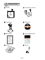
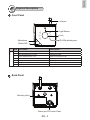
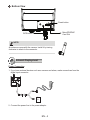
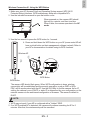
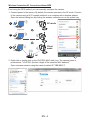
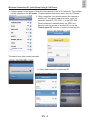
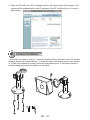
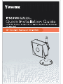
English
Warning Before Installation
Power off the Network Camera as
soon as smoke or unusual odors are
detected.
Keep the Network Camera away
from water. If the Network Camera
becomes wet, power off immediately.
Do not place the Network Camera
around heat sources, such as a
television or oven.
Refer to your user’s manual for the
operating temperature.
Keep the Network Camera away from
direct sunlight.
Do not place the Network Camera in
high humidity environments.
Do not place the Network Camera on
unsteady surfaces.
Do not touch the Network Camera
during a lightning storm.
Do not disassemble the Network
Camera.
Do not drop the Network Camera.
Do not insert sharp or tiny objects
into the Network Camera.
EN - 1
1
Package Contents
IP8336W
Power Adaptor (+12V, 2A)
Camera Stand
Software CD
500024701G
Warranty Card
Quick Installation Guide
Screws
Antenna
EN - 2
English
2
Physical Description
Front Panel
Antenna
Light Sensor
Lens
IR LEDs behind panel
Microphone
Status LED
LED Definitions
Item LED status
Description
1
2
3
4
5
6
7
Powered and system booting, or network failed
Searching for WPS
Network connected to an AP
Upgrading firmware
Operating in camera default AP mode
Restoring defaults
Powered off
Steady Red
Blue LED blinks every 0.15 sec.
Green LED blinks every 1 sec.
Green and RED blink consecutively every 0.15 sec.
Steady Blue
Orange blinks every 0.15 sec.
All LED off
Back Panel
Mounting Hole
Power and I/O Combo Cable
EN - 3
Bottom View
Reset button
MicroSD/SDHC
Card Slot
WPS button
NOTE:
An antenna comes with the camera. Install it by turning
clockwise to attach to the connector.
3
Network Deployment
Power Connection
1. If you have external devices such as a sensors and alarm, make connections from the
digital input connector.
DI+
DI-
2. Connect the power line to the power adaptor.
EN - 4
English
Wireless Connection #1: Using the WPS Button
1. Make sure your AP (Access Point) and Operating System support WPS (Wi-Fi
Protected Setup) functions. WPS enables easy setup with compatible APs.
2. Use the included hex wrench to open the bottom cover.
When powered on, the camera LED should
light red for a minute, and then turn blue.
When lit blue, the camera operates in the AP
mode.
3. Use the hex wrench to press the WPS button for 1 second.
4. Press and hold down the WPS button on your AP (some router/AP will
have a virtual button on their management software instead). Refer to
your AP's documentation for details using its WPS functions.
Wireless AP
WPS
WPS Button
WPS Button
The camera LED should flash green. When WPS configuration is done, wireless
connectivity will be established and the security encryption, such as WEP or WPAPSK, will be synchronized with the AP. Use the IW2 utility to find the camera. As for IP
setting, the camera's use of DHCP or static IP is determined by your configuration on the
network camera via the web-based configuration of firmware. The camera's default is
DHCP.
NOTE:
1. WPS may not work if your AP is configured with a "hidden" SSID.
2. If no WPS-enabled AP is detected, the camera will continue searching for AP for 2
minutes. After that, the wireless setup will be cancelled.
EN - 5
Wireless Connection #2: Connection without WPS
If not using the WPS method, you can manually configure the camera:
1. Connect power to the camera. By default, the camera operates in the AP mode. Connect
to the camera using a Wi-Fi capable notebook or a computer with a wireless adaptor.
Open the internet dialog box by clicking the wireless networks icon on the system tray.
1
AP mode
2
VIVOTEK (1C:CC)
Client
mode
3
AP
2. Right-click or double-click on the VIVOTEK (MAC addr) icon. The camera name is
presented as: "VIVOTEK: (the last 4 digits of the camera's MAC address)."
Open a browser session using the camera's default IP "192.168.1.1"
EN - 6
3. Enter your wireless AP's SSID and security password to connect to an existing AP. You
may also use the "Search your AP" button to locate an AP of your preferrence. Doubleclick on an AP to make the connection.
Select the security encryption, such as
WEP or WPA-PSK, the algorithm, and
enter the pre-share key. Click Save to
proceed.
The camera will then operate in the
Client mode.
EN - 7
English
You can also discover the camera
using the IW2 utility. Install the IW2
utlity from the included product CD.
4. Open the IW2 utility. The camera will be assigned with a new IP address. Double-click
on it to start a web session. The camera LED will start blinking green by every second.
NOTE:
When you encounter configuration errors,
you can press the WPS button for 5
seconds to restore network settings. The
camera will resume the AP mode and the
LED will light blue.
WPS
5. A browser session with the Network Camera should prompt as shown below.
6. You should be able to see live video from your camera. You may also install the
32-channel recording software from the software CD in a deployment consisting of
multiple cameras. For its installation details, please refer to its related documents.
2011/01/05 01:50:28
EN - 8
English
Wireless Connection #3: Initial Setup Using a Cell Phone
1. Connect power to the camera. Search for the camera in the Wi-Fi Networks. The camera
initially operates in the AP mode. Screen captures have been taken from an iPhone®.
2. Once connected, you should connect the camera to
another AP. You should open a browser, enter the
camera's default IP (192.168.1.1) in the URL field.
When connected, manually enter the SSID and
security code for access to another AP, or use the
"Search your AP" function to search for nearby APs.
VIVOTEK (1C:CC)
The search may take several seconds.
3. Select and connect to a preferred AP.
EN - 9
4. Open the IW2 utility on a PC or laptop located in the same subnet of the camera. The
camera will be assigned with a new IP address by the AP. Double-click on it to start a
web session.
4
Hardware Installation
1. Drill holes on a wall or ceiling. 2. Insert the plastic anchors, and then mount the camera
stand by driving the included screws. 3. Close and secure the bottom cover if you opened
it. 4. Attach the camera by turning it around the threaded mount. 5. Adjust the camera's
shooting angle and secure the camera to the stand.
EN - 10