1
Documentation
OpenScape Voice, Sylantro, Broadsoft
optiPoint 410/420 advance S V7.0
optiPoint 410/420 economy/standard S V7.0
optiPoint 410 entry S V7.0
Trace Guide
Communication for the open minded
Siemens Enterprise Communications
www.siemens-enterprise.com
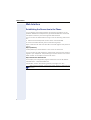
Safety Precautions
Safety Precautions
Important Notes
Do not operate the telephone in environments where there is
a danger of explosions.
Use only original Siemens accessories. Using other accessories may be dangerous, and will invalidate the warranty and
the CE mark.
Never open the telephone or a key module. If you encounter
any problems, contact System Support.
Attention
7 If the optiPoint 410/420 S V6.0 is supplied with power over the LAN
interface Æ page 42, the power source must be a limited power
source PowerHub compliant with IEC 60950.
•
•
•
•
•
•
This equipment has been tested and found to comply with the limits
for a Class B digital device, pursuant to Part 15 of the FCC Rules. These
limits are designed to provide reasonable protection against harmful interference when the equipment is operated in a commercial environment.
This equipment generates, uses, and can radiate radio frequency energy and, if not installed and used in accordance with the instructions,
may cause harmful interference to radio communications.
Operation of this equipment in a residential area is likely to cause harmful interference, in which case the user will be required to correct the
interference at his own expense.
The IP telephone optiPoint 410/420 S V6.0 complies with the European
standard EN 60 950.
The earpiece in this telephone handset contains a magnet. To prevent
injury, before each use ensure objects such as pins or staples are not
stuck to the earpiece.
There is always the danger of small objects being swallowed by young
children. In the case of the optiPoint 410/420 S V6.0, this applies in particular to the connecting cord clip.
Please make sure that such items are not accessible to children.
Never allow the telephone to come into contact with staining or corrosive liquids, such as coffee, tea, juice or soft drinks.
The information provided in this document contains merely general descriptions or characteristics of performance features which in case of actual use do not always apply as described or which may change as a result
of further development of the products.
2
Safety Precautions
An obligation to provide the respective performance features only exists if
expressly agreed in the terms of contract.
Note! (for U.S.A and Canada only)
This equipment has been tested and found to comply with the limits
for a Class B digital device, pursuant to Part 15 of the FCC Rules.
These limits are designed to provide reasonable protection against
harmful interference when the equipment is operated in a residential installation. This equipment generates, uses, and can radiate radio frequency energy and, if not installed and used in accordance
with the instructions, may cause harmful interference to radio communications. However, there is no guarantee that interference will
not occur in a particular installation. If this equipment does cause
harmful interference to radio or television reception, which can be
determined by turning the equipment off and on, the user is encouraged to try to correct the interference by one or more of the following measures:
• Reorient or relocate the receiving antenna.
• Increase the separation between the equipment and receiver.
• Connect the equipment into an outlet on a circuit different from
that to which the receiver is connected.
• Consult the dealer or an experienced radio/TV technician for
help.
This product is a UL Listed Accessory, I.T.E., in U.S.A. and Canada.
Location of the Telephone
• The telephone should be operated in a controlled environment with an
ambient temperature between 5 °C and 40 °C (41 °F and 104 °F).
• To ensure good handsfree talking quality, the area in front of the microphone (front right) should be kept clear. The optimum handsfree distance is 20 inches (50cm).
• Do not install the telephone in a room where large quantities of dust
accumulate; this can considerably reduce the service life of the telephone.
• Do not expose the telephone to direct sunlight or any other source of
heat, as this is liable to damage the electronic equipment and the plastic casing.
• Do not operate the telephone in damp environments such as bathrooms.
Telephone Maintenance
• Always use a damp or antistatic cloth to clean the telephone. Never
use a dry cloth.
• If the telephone is very dirty, clean it with a diluted neutral cleaner containing some form of surfactant, such as a dish detergent. Afterwards,
remove all traces of the cleaner with a damp cloth (using water only).
• Never use cleaners containing alcohol, cleaners that corrode plastic, or
abrasive powders.
3
Safety Precautions
Labels
The device conforms to the EU guideline 1999/5/EG, as attested by the CE mark.
This device has been manufactured in accordance with our
certified environmental management system (ISO 14001).
This process ensures that energy consumption and the use
of primary raw materials are kept to a minimum, thus reducing waste production.
All electrical and electronic products should be disposed of
separately from the municipal waste stream via designated
collection facilities appointed by the government or the local
authorities.
The correct disposal and separate collection of your old appliance will help prevent potential negative consequences
for the environment and human health. It is a precondition
for reuse and recycling of used electrical and electronic
equipment.
For more detailed information about disposal of your old appliance, please contact your city office, waste disposal service, the shop where you purchased the product or your sales representative.
The statements quoted above are only fully valid for equipment which is installed and sold in the countries of the European Union and is covered by the directive 2002/96/EC.
Countries outside the European Union may have other regulations regarding the disposal of electrical and electronic
equipment.
4
Contents
Contents
Safety Precautions . . . . . . . . . . . . . . . . . . . . . . . . . . . . 2
HowTo handle internal phone traces on optiPoint
410/420 S . . . . . . . . . . . . . . . . . . . . . . . . . . . . . . . . . . . . . 7
Reason for this HowTo . . . . . . . . . . . . . . . . . . . . . . . . . . . . . . . . . . . . . . 7
Pre-Conditions . . . . . . . . . . . . . . . . . . . . . . . . . . . . . . . . . . . . . . . . . . . . . 7
Activate internal phone traces . . . . . . . . . . . . . . . . . . . . . . . . . . . . . . . . . 8
Read out the internal phone traces . . . . . . . . . . . . . . . . . . . . . . . . . . . . . 9
Deactivate internal phone traces . . . . . . . . . . . . . . . . . . . . . . . . . . . . . . 11
optiPoint SIP UDP Trace. . . . . . . . . . . . . . . . . . . . . . . 12
Activate the UDP Trace . . . . . . . . . . . . . . . . . . . . . . . . . . . . . . . . . . . . . 12
Enable the SIP UDP Trace . . . . . . . . . . . . . . . . . . . . . . . . . . . . . . . . . . . 12
Web Interface. . . . . . . . . . . . . . . . . . . . . . . . . . . . . . . . 14
Establishing the Connection to the Phone . . . . . . . . . . . . . . . . . . . . . .
Access to the Web Interface Administrator Menu . . . . . . . . . . . . .
Administrations Menu . . . . . . . . . . . . . . . . . . . . . . . . . . . . . . . . . . .
Additional Web Pages for Tests and Tracing. . . . . . . . . . . . . . . . . . . . .
Non user-assisted tests . . . . . . . . . . . . . . . . . . . . . . . . . . . . . . . . . .
User-assisted tests . . . . . . . . . . . . . . . . . . . . . . . . . . . . . . . . . . . . .
RTP Statistics . . . . . . . . . . . . . . . . . . . . . . . . . . . . . . . . . . . . . . . . .
QoS Data Collection. . . . . . . . . . . . . . . . . . . . . . . . . . . . . . . . . . . . .
Fault Investigation . . . . . . . . . . . . . . . . . . . . . . . . . . . . . . . . . . . . . . . . .
Trace Configuration . . . . . . . . . . . . . . . . . . . . . . . . . . . . . . . . . . . . .
Trace View . . . . . . . . . . . . . . . . . . . . . . . . . . . . . . . . . . . . . . . . . . .
Simplified trace page . . . . . . . . . . . . . . . . . . . . . . . . . . . . . . . . . . .
FTP Client . . . . . . . . . . . . . . . . . . . . . . . . . . . . . . . . . . . . . . . . . . . .
Exception Data . . . . . . . . . . . . . . . . . . . . . . . . . . . . . . . . . . . . . . . .
Windview Configuration . . . . . . . . . . . . . . . . . . . . . . . . . . . . . . . . .
SIP UDP Trace . . . . . . . . . . . . . . . . . . . . . . . . . . . . . . . . . . . . . . . .
14
15
16
17
17
18
19
20
22
23
24
24
25
25
26
26
5
Contents
Alphabetical Reference . . . . . . . . . . . . . . . . . . . . . . .27
Description of Functions . . . . . . . . . . . . . . . . . . . . . . . . . . . . . . . . . . . .
Audio loop test. . . . . . . . . . . . . . . . . . . . . . . . . . . . . . . . . . . . . . . . .
Display test . . . . . . . . . . . . . . . . . . . . . . . . . . . . . . . . . . . . . . . . . . .
Key test . . . . . . . . . . . . . . . . . . . . . . . . . . . . . . . . . . . . . . . . . . . . . .
LED test. . . . . . . . . . . . . . . . . . . . . . . . . . . . . . . . . . . . . . . . . . . . . .
Line monitor. . . . . . . . . . . . . . . . . . . . . . . . . . . . . . . . . . . . . . . . . . .
Ping . . . . . . . . . . . . . . . . . . . . . . . . . . . . . . . . . . . . . . . . . . . . . . . . .
QDC Address . . . . . . . . . . . . . . . . . . . . . . . . . . . . . . . . . . . . . . . . .
QDC Port . . . . . . . . . . . . . . . . . . . . . . . . . . . . . . . . . . . . . . . . . . . .
RAM test . . . . . . . . . . . . . . . . . . . . . . . . . . . . . . . . . . . . . . . . . . . . .
ROM test . . . . . . . . . . . . . . . . . . . . . . . . . . . . . . . . . . . . . . . . . . . . .
Trace Easy Automatic Clear Before Start. . . . . . . . . . . . . . . . . . . . .
Trace Easy Empty log . . . . . . . . . . . . . . . . . . . . . . . . . . . . . . . . . . .
Trace Easy File Size . . . . . . . . . . . . . . . . . . . . . . . . . . . . . . . . . . . . .
Trace Easy Refresh . . . . . . . . . . . . . . . . . . . . . . . . . . . . . . . . . . . . .
Trace Easy Reset Settings . . . . . . . . . . . . . . . . . . . . . . . . . . . . . . . .
Trace Easy Stop logging . . . . . . . . . . . . . . . . . . . . . . . . . . . . . . . . .
Trace Easy Submit/Start logging . . . . . . . . . . . . . . . . . . . . . . . . . . .
Trace Easy Trace Setting Template . . . . . . . . . . . . . . . . . . . . . . . . .
Trace Easy Timeout . . . . . . . . . . . . . . . . . . . . . . . . . . . . . . . . . . . . .
Trace FTP Client Download . . . . . . . . . . . . . . . . . . . . . . . . . . . . . . .
Trace FTP Client Upload . . . . . . . . . . . . . . . . . . . . . . . . . . . . . . . . .
Trace Level . . . . . . . . . . . . . . . . . . . . . . . . . . . . . . . . . . . . . . . . . . .
Trace Output . . . . . . . . . . . . . . . . . . . . . . . . . . . . . . . . . . . . . . . . . .
Trace Streamsl. . . . . . . . . . . . . . . . . . . . . . . . . . . . . . . . . . . . . . . . .
Trace Timeout . . . . . . . . . . . . . . . . . . . . . . . . . . . . . . . . . . . . . . . . .
Trace View Source. . . . . . . . . . . . . . . . . . . . . . . . . . . . . . . . . . . . . .
Trace View File Stream . . . . . . . . . . . . . . . . . . . . . . . . . . . . . . . . . .
Trace Windview Configuration Logging Level . . . . . . . . . . . . . . . . .
Trace Windview Configuration Reset . . . . . . . . . . . . . . . . . . . . . . .
Abbreviations and Specialized Terms . . . . . . . . . . . . . . . . . . . . . . . . . .
27
27
27
28
28
28
29
29
30
30
30
31
31
31
31
32
32
32
32
32
33
33
33
34
35
37
38
38
39
39
40
Index. . . . . . . . . . . . . . . . . . . . . . . . . . . . . . . . . . . . . . . .45
6
HowTo handle internal phone traces on optiPoint 410/420 S
HowTo handle internal phone traces on
optiPoint 410/420 S
Trace Configuration is used to inform the phone of which information is to
be logged.
The "Trace output" drop down box is used to tell the phone whether to
store the information to the File associated with the application stream or
log the information to the generic memory buffer.
Both tracing to memory and tracing to file behave as circular buffers. The
difference between 'trace output memory' and 'trace output file' is that
tracing to memory logs trace records to a circular memory buffer which will
be lost on a power on reset, while trace to file saves records to various files
on flash. The reason for having both methods is that in the case of general
functional faults, tracing to memory is the preferred option as this will have
a lower impact on phone performance (this is because writing to flash is
relatively slow and flash has a limited number of write cycles) while tracing
to flash should only be used when investigating problems that require
trace data to be retained over phone resets. All trace data should be accessible via the Web interface and thus should not require an FTP server for
access.
1. Reason for this HowTo
2. Pre-Conditions
3. Activate internal phone traces
4. Read out the internal phone traces
5. Deactivate internal phone traces
Reason for this HowTo
Sometimes development is not able to pinpoint a problem with network
traces only. It could happen that the message flow is correct but the phone
behavior is not as it should be. For those cases the phones are able to
trace internal processes that show the development what is going wrong.
The steps for activating / reading out / deactivating those traces are mostly
the same. With this HowTo in hands the requester must only define which
traces he needs.
Pre-Conditions
Ensure that the phone is configured with a working SNTP server to have
the correct time available in the traces.
– If no SNTP server is available, ensure that the correct time is configured manually.
If it is asked to deliver the internal phone traces in combination with some
other traces (e.g. Wireshark) it is necessary that the trace-pc has configured the same SNTP server as the phone
– If no SNTP server is available, ensure that you’ve configured the
same time on all tracing devices.
7
HowTo handle internal phone traces on optiPoint 410/420 S
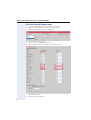
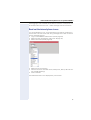
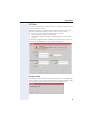
Activate internal phone traces
•
•
•
Log-in to the WBM as administrator (see Æ page 15)
Select the Fault Investigation menu (see Æ page 22)
Select Trace Configuration (see Æ page 23)
•
•
•
Choose File as Trace Output.
Set the timeout to 9999 minutes (max).
Activate the checkbox for “Automatic clear before start”.
•
Choose/set the parameter as seen on the picture above if nothing else
has been requested.
Click on the Submit button.
•
8
HowTo handle internal phone traces on optiPoint 410/420 S
Trace logging is now activated and all relevant activities of the phone will
be saved (till the trace file is full – oldest messages will be overwritten.
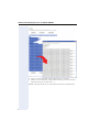
Read out the internal phone traces
It is recommended to wait ~3 minutes before you read out the phone internal traces. This will ensure that all log messages are written to the file
and no messages are lost.
• Log-in to the WBM as administrator (see Æ page 15)
• Select the Fault Investigation menu (see Æ page 22)
• Select Trace View (see Æ page 24)
•
•
•
Select File as Trace Source.
Choose one of the activated traces (usually Error, SIP UI, SIP Call Control and SIP Signalling).
Click on Submit.
The selected stream is now displayed in your browser.
9
HowTo handle internal phone traces on optiPoint 410/420 S
•
•
Copy all content between the grey Buttons into a text-file.
Save it to your computer, using a clear name (e.g. for each stream a
separate file: Error.txt; SIP UI.txt …)
Repeat the steps above till you have copied all traces to separate files.
10
HowTo handle internal phone traces on optiPoint 410/420 S
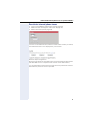
Deactivate internal phone traces
•
•
•
Log-in to the WBM as administrator (see Æ page 15)
Select the Fault Investigation menu (see Æ page 22)
Select Trace View (see Æ page 24)
Just click on the Submit button (It doesn’t matter which stream you select).
The selected stream is now displayed in your browser.
Push the Stop tracing button.
By clicking this button all activated traces will automatically be deactivated.
(The SIP UDP Trace is a separate trace and will not be deactivated.)
It is recommended to deactivate the traces after they have been saved to
disburden the phone as much as possible.
11
optiPoint SIP UDP Trace
optiPoint SIP UDP Trace
If problems in operating the optiPoint 410/420 S phones are encountered,
showing a display message like "no server" or "Registering..." for a longer
time, then these problems are likely to be related to the signalling with the
SIP proxy or registrar. It is often helpful to capture the messages with a network hub and display these data with one of the well known tools to examine the problem in more detail.
If no hub is available or a PC trace tool cannot be used for some reason,
the build in SIP UDP trace of the optiPoint can be used as well.
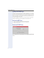
Activate the UDP Trace
•
•
•
Log-in to the WBM as administrator (see Æ page 15)
Select the Fault Investigation menu (see Æ page 22)
Select SIP UDP Trace
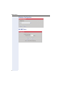
Enable the SIP UDP Trace
To enable SIP UDP tracing simply click the Trace enable box and set the log
file to a suitable size, for example 5000K. Click the Submit button to active
logging.
12
optiPoint SIP UDP Trace
Once tracing is complete the SIP log can be viewed as indicated on the
above screen shot by clicking on the word here.
The message log can be deleted afterwards.
Do not forget to de-activate the SIP UDP Trace when tracing is no
longer required – tracing is consuming ressources and performance.
13
Web Interface
Web Interface
Establishing the Connection to the Phone
You can display and configure device and network information for the
optiPoint 410/420 /economy/economy plus/standard/advance S V7.0 and
the optiPoint 410 entry S V7.0 through the Web Interface.
You can access the Web Interface using one of the following web browsers:
• Microsoft Internet Explorer (recent version recommended)
To access the Web Interface, perform the following steps.
Open a web browser and enter the URL of the web page for the phone as
follows:
https://[address]
where [address] is the IP address or host name of the Phone.
You can access the web interface in the browser using the host name assigned to your telephone. The presetting for the host name is the current
E164 number. An example for the browser call is:
https://hostname.domainname
For example, the configuration page for the Phone with the IP address
192.168.1.137 is: "https://192.168.1.137".
If applicable, confirm the following advisory message with "Yes":
After entering the URL, the browser might display a certificate notification.
14
Web Interface
A screen like the following home page appears:
Click on the required field in the dialogs to see a description for
each parameter.
Access to the Web Interface Administrator Menu
The following steps describe the access to the administrator menu, starting from the home page of the optiPoint 410/420.
1. Click on the link "Administration". The following login dialog appears:
2. Enter the administrator password (default: "123456"; max length 24
digits) and confirm.
15
Web Interface
Administrations Menu
Administrator menu
z Trace Configuration
z Network IP and Routing
z Trace View
z System
z Simplified trace page
°
SIP environment
z FTP Client
°
SIP features
z Exception Data
z Quality of service
z Windview Configuration
z File transfer and phone download settings
z SIP UDP Trace
z Time and date
z SNMP
z Speech
z Ringer settings
z LAN Port settings
z Multiline operation
z Function keys...
{
Phone
{
Key module 1
{
Key module 2
{
Key module SLK 1
{
Key module SLK 2
z Dial plan
z Dialing properties
z Feature Access
z User Mobility
z Configuration Management...
{
Settings
{
Check for updates
{
Error log
z Applications...
z
{
Directory
{
Address Book
{
WAP
Upload/Download...
°
Upload configuration
°
Download application
°
Download configuration
°
Download hold music
z Diagnostics and statistics...
{
Non user-assisted tests
{
User-assisted tests
{
RTP Statistics
{
QoS Data Collection
{
Fault investigation
{
Simplified trace page
z Security
z Restart terminal
z Reset user password
z Change admin password
z Clear all user data
z Restore factory setting
z Port Control
z FPN Port Settings
z Survivability
Home
16
Fault Investigation
z General Information
Web Interface
Additional Web Pages for Tests and Tracing
The web menus relevant for tests and tracing are listed below. If you click
on one of the menu options, you will be directed to further explanations in
the alphabetical reference.
Non user-assisted tests
17
Web Interface
User-assisted tests
optiPoint 410/420 standard/advance
optiPoint 410/420 economy/economy plus and optiPoint 410 entry
Not used with
optiPoint 410 entry
18
Web Interface
RTP Statistics
These parameters are used for development only.
19
Web Interface
QoS Data Collection
These parameters are used for development only.
20
Web Interface
Session data
Æ page 20
21
Web Interface
Fault Investigation
Available tracing menus (selected in “Administrations Menu” on page 16:
•
•
•
•
•
•
•
22
“Trace Configuration” on page 23
“Trace View” on page 24
“Simplified trace page” on page 24
“FTP Client” on page 25
“Exception Data” on page 25
“Windview Configuration” on page 26
“SIP UDP Trace” on page 26
Web Interface
Trace Configuration
Trace Configuration is used to inform the phone of which information is to be
logged.
23
Web Interface
Trace View
Trace View is used to retrieve trace information from the phone.
Simplified trace page
It is a simple interface for the user for an easy trace setup and data retrieval. This functionality is to be used as the usual standard procedure when
investigating problems (first-time). It provides a simple access to trace information that can be used in a frequent number of support-cases.
The Easy Trace functionality gives the user the opportunity to collect multiple streams into a common log file.
24
Web Interface
FTP Client
To use the FTP client you will need the "Host", "username" and "password"
of your FTP server account.
Where File details are required "Local File details" refers to files on the
phone and "Remote File details" refers to files on the FTP server.
• The root directory of the phones file system is "/tffs0/".
• Trace log files are located in "/tffs0/tracing"
• The exception log file is located in "/tffs0/exceptions/" and is called
"exc.txt".
If "Windview" logging has been enabled, the windview log if it exists can
be found in "/tffs0/exceptions/" and is called "wdvlog.wvr".
Exception Data
It is possible to get the reason for a phone reset by use of this WEB page.
Click on submit. You will then be presented with a page of exception data.
This information can be used to discover the cause of the reset.
25
Web Interface
Windview Configuration
SIP UDP Trace
26
Alphabetical Reference
Alphabetical Reference
This reference offers basic information that can be used by the administrator to carry out administration- and diagnostics-related jobs in the
optiPoint 410/420 family S V7.0.
• The Chapter explains alphabetically sorted terms that, for instance,
you will encounter in the menus.
Used symbols:
–
Shows administration tasks with menu paths at the
optiPoint 410/420 family S V7.0 and on the Web Interface.
–
Shows the related Web Interface surfaces.
– Y Refers to the User Manual if required.
• This is followed by the Chapter “Abbreviations and Specialized Terms“.
Description of Functions
Audio loop test
•
•
The test activates the microphone and the loudspeaker in the handset.
You can check these components by speaking and listening.
Æ page 18
Display test
•
•
Conduct this test to check the function of the Æ LCD display in the Display telephone.
Different display contents are displayed with the < and > keys. The
: key terminates the test.
Æ page 18
27
Alphabetical Reference
Key test
•
•
Test to check the functions of the telephone keys.
If you press a key on the optiPoint 410/420 family S V7.0 (except the
: key), the associated LED lights up and the corresponding name is
displayed in the Æ LCD display. The : key terminates the test.
Æ page 18
LED test
•
•
Run this test to check the function of the Æ LEDs at the optiPoint 410/
420 family S V7.0.
During the test all LEDs are flashing. The : key terminates the test.
Æ page 18
Line monitor
•
•
Activate the display to view the functions and values used to run the
Æ LAN connections at the phone.
The status monitor remains active even during the normal operation of
the optiPoint 410/420 family S V7.0. However, it does not affect the operation of the function keys.
Line Monitor information optiPoint 410
LAN Port 1 (LAN)
10 Mb/s Full duplex
LED:
10 Mb/s Half duplex
LED:
9, 11
9
100 Mb/s Full duplex
LED:
9, 10, 11
100 Mb/s Half duplex
LED:
9, 10
10 Mb/s Full duplex
LED:
5, 7
10 Mb/s Half duplex
LED:
5
100 Mb/s Full duplex
LED:
5, 6, 7
100 Mb/s Half duplex
LED:
5, 6
LAN Port 2 (PC)
Explanation report:
LED 9 or 5 'on'
28
Connection established
LED 9 or 5 'off'
Connection not established
LED 6 or 10 'on'
100 Mb/s connection
LED 6 or 10 'off'
10 Mb/s connection
LED 7 or 11 'on'
Full duplex connection
LED 7 or 11 'off'
Half duplex connection
Alphabetical Reference
Line Monitor information optiPoint 420
LAN Port 1 (LAN)
10 Mb/s Full duplex
LED:
10, 12
10 Mb/s Half duplex
LED:
10
100 Mb/s Full duplex
LED:
10, 11, 12
100 Mb/s Half duplex
LED:
10, 11
10 Mb/s Full duplex
LED:
6, 8
10 Mb/s Half duplex
LED:
6
100 Mb/s Full duplex
LED:
6, 7, 8
100 Mb/s Half duplex
LED:
6, 7
LAN Port 2 (PC)
Explanation report:
LED 10 or 6 'on'
Connection established
LED 10 or 6 'off'
Connection not established
LED 7 or 11 'on'
100 Mb/s connection
LED 7 or 11 'off'
10 Mb/s connection
LED 8 or 12 'on'
Full duplex connection
LED 8 or 12 'off'
Half duplex connection
Æ page 18
Ping
•
•
•
Run this Æ PING test to check whether a server or another terminal device (e.g. the optiPoint 410/420 family S V7.0 or servers) can be
reached by Æ IP or domain name.
For this, enter or select an Æ IP address or domain name as a test target (the connection to which you wish to test).
Value range table (for user specified IP):
Permitted values
numeric (with DNS also alphanumeric)
Length max.
15 digits (incl. dots)
(with DNS also 92 digits)
Æ page 17
QDC Address
Enter IP address of the Quality Data Collection Server. For more information refer to HiPath QoS Data Collection V1.0 Interface Description.
Æ page 20
29
Alphabetical Reference
QDC Port
Enter port address of the Quality Data Collection Server. For more information refer to HiPath QoS Data Collection V1.0 Interface Description.
Æ page 20
RAM test
•
•
Use this function to test the Æ RAM memory of your optiPoint 410/
420 family S V7.0.
The results are displayed after the test.
Æ page 17
ROM test
•
•
Use this function to test the Æ ROM memory of your optiPoint 410/
420 family S V7.0.
The results are displayed after the test.
Æ page 17
30
Alphabetical Reference
Trace Easy Automatic Clear Before Start
When it is clicked in, the loggings are cleared every start, when it is not
clicked you can see the pervious loggings. The use of this checkbox is independent from the full trace functionality. It means that only the easytrace log file is emptied, but not the streams for the full trace functionality.
Æ page 24
Trace Easy Empty log
Removes any stored logging data(only the status line and the header remain displayed)
Æ page 24
Trace Easy File Size
The file size should be between 4096 and 524288 (bytes).
Æ page 24
Trace Easy Refresh
Retrieves and displays any new logging data.
Æ page 24
31
Alphabetical Reference
Trace Easy Reset Settings
Set parameters to default values.
Æ page 24
Trace Easy Stop logging
Stops the current logging action.
Æ page 24
Trace Easy Submit/Start logging
Store the new parameter values in the database and start the trace. All the
parameter settings on this easy trace page are independent from the full
trace settings.
Note: It is also important that at any given time only one kind of trace can
be active. Either easy tracing or full tracing. It means that the starting of an
easy tracing automatically blocks the active full tracing, and conversely, if
the full tracing is started it stops the active easy tracing.
Only the parameters which are set on this easy trace page, have impact on
the easy tracing, and only the parameters which are set on full trace page,
have impact on full tracing.
Æ page 24
Trace Easy Trace Setting Template
Predefined templates covering the most important trace-scenarios, each
template is for one frequently used support case (trace-scenario) like:
• Audio
• IP Networking
• SIP signalling
• Application failure
• Maintenance.
Each template has the corresponding components with trace levels, which
are inputs for the tracer.
Æ page 24
Trace Easy Timeout
The time duration while the tracing should be active, the Timeout value
should be between 1 and 9999 (minutes).
Æ page 24
32
Alphabetical Reference
Trace FTP Client Download
To put files on to the phone fill in the "Host", "username" and "password" of
your FTP server account. Fill in the "Remote File details" (This where you
want the file to go on your FTP server). Fill in the "Local File details" (This
is the file you want to retrieve from the phone).
Æ page 25
Trace FTP Client Upload
To retrieve files from the phone fill in the "Host", "username" and "password" of your FTP server account. Fill in the "Remote File details" (This
where you want the file to go on your FTP server). Fill in the "Local File details" (This is the file you want to retrieve from the phone).
Æ page 25
Trace Level
Except for the Error stream, it is possible to set the level of tracing on any
specified stream. Six levels of tracing are available:
• None
• High Level
• Black Box External/Internal
• White Box
• All
There is an additional logging level which is the error level. As long as the
tracing level is not set to "None", errors on this stream will be logged. There
follows a description of the type of information which will be logged at
each trace level. When 'All' is selected then the trace will contain messages from all levels.
•
High level
would include:
– task creation and deletion,
– message queue creation and deletion,
– pipe creation and deletion,
– semaphore creation and deletion
– Monitoring of task stack
– Monitoring of task activity
– Monitoring of free heap memory
– Monitoring of spare file descriptors
– Monitoring of spare space on the file system
•
Black box (external)
would include:– Indication of incoming network messages from sockets
– Indication of outgoing network messages to sockets
– Indication of incoming network messages from 3rd party software
– Indication of outgoing network messages to 3rd party software
33
Alphabetical Reference
– Indication of input messages from device drivers/device interfaces
– Indication of output messages to device drivers or device interfaces
•
Black box (internal or task)
would include:
– Indication of incoming message from message queues or pipes
– Indication of outgoing message indication onto message queues or
pipes
– Giving and taking of inter-task semaphores
– Changes to data stored in the file system
– Heap memory allocation and de-allocation
•
White box (internal or task)
would include:
– Function entry (parameter data ?)
– Function exit (return value data ?)
– Logical flow within function
– Changes to internal memory variables (critical logic only)
It should be pointed out that Errors directed at the ERROR stream will still
be logged. Only errors directed at the specific stream will not be logged.
Æ page 23
Trace Output
The "Trace output" drop down box is used to tell the phone whether to
store the information to the File associated with the application stream or
log the information to the generic memory buffer.
Both tracing to memory and tracing to file behave as circular buffers. The
difference between 'trace output memory' and 'trace output file' is that
tracing to memory logs trace records to a circular memory buffer which will
be lost on a power on reset, while trace to file saves records to various files
on flash. The reason for having both methods is that in the case of general
functional faults, tracing to memory is the preferred option as this will have
a lower impact on phone performance (this is because writing to flash is
relatively slow and flash has a limited number of write cycles) while tracing
to flash should only be used when investigating problems that require
trace data to be retained over phone resets. All trace data should be accessible via the Web interface and thus should not require an FTP server for
access.
Æ page 23
34
Alphabetical Reference
Trace Streamsl
It should be noted again that performance of the phone can be seriously
affected, and trace messages lost, if too many components are traced at
once. A lost trace message indication is given in the Error log to memory
when a write to file was not possible. Messages are lost because of the
slow write cycle of the Flash memory.
Enabling tracing in most components will slow down the phone but message handling components, for example SIP Signalling, are more susceptible. User level applications such as ENB and LDAP are less critical components, although the effect is not measurable.
There follows a brief description of each traceable component. High level,
Black box (external) and Black box (internal) are general use streams which
do not relate to specific software modules so are not described here.
•
Monitor
The Monitor provides a resilience service. It allows other components'
tasks to register for monitoring. Once registered a component task is
obliged to report to the Monitor within a certain time period. If the task
does not report in to the Monitor, the Monitor will restart the phone.
The Monitor is responsible for periodically kicking the hardware watchdog. If the hardware watchdog is not kicked the phone will restart.
•
Service Agent
The IP-Phone device contains various services that are accessible to
external clients via TCP/IP. These services are not ordinarily running in
the device, so clients that require access to a service within the device
must somehow launch the service on the device. This is achieved by
having a minimal task that is always running that listens for incoming
messages on a UDP socket on a fixed port. This task is called the "IP
Service Agent".
The IP Service Agent also provides a means for the auto-discovery of
devices on the network. As the IP Service Agent processes UDP "connectionless" messages it can receive UDP messages that are broadcast over the network. The Service Agent can process the UDP messages and respond to the client, allowing the client to locate a particular
device.
•
CTI Server
This feature is not supported .
•
Resource Sharing
The concept of the Resource Sharing feature is to allow PC and IP
Phone users the ability to use the PC keyboard and mouse to enter text
and navigate on the IP Phone. There is no feedback on the PC, and consequently it is assumed that the user, PC, and IP Phone will be in close
physical proximity.
•
The Resource Sharing facility makes use of the IP LAN to pass (UDP)
messages between the PC client, and the Service Agent to initialise
the Resource Sharing server task. The configuration of the IP Phone
35
Alphabetical Reference
details on the PC, and the selected initialisation method for the communications path, may require that both elements are also on the same
segment, so that UDP broadcasts are not filtered by a router
36
•
Home App
An application called the Home Application is provided as part of the
Application Framework component group. The Application Framework
is intended to provide an environment for the applications that will run
on the optiPoint 410/420 range. The Home Application provides access
to all applications that are available on the phone.
•
SIP UI
The UI provides the driver applications for the two and four line displays
of the phone. It also holds state information relating to the current and
previous states of the phone in the current processing task. It provides
the interface between the user and the call control element of the application.
•
SIP Database
The SIP database layer handles all interactions between the phone application and the configuration files. It also provides the interface layer
to the data registry.
•
SIP Call Control
The call control application provides the interface between the user (via
the UI) and the signalling element. On incoming calls it provides the UI
with state information of the progress of the incoming call. It also uses
information from the user to cause signalling to initiate an outgoing call.
•
SIP Signalling
This component provides the interface between the SIP protocol stack
and the phone application. For incoming calls it creates the appropriate
data structures, manages these data structures and passes messages
up to call control to ensure the phone is always in the correct state. This
component is also responsible for responding to requests from call
control to create outgoing calls.
•
SIP Os Utils
This component encompasses all calls from the SIP application to the
low level operating system.
•
RTP
The RTP trace option outputs log messages from the RTP session and
Jitter buffer components. RTP (Realtime Transport Protocol) is the protocol specified by H.323 to carry the speech packets in a call.
•
System Framework
The Application Framework is intended to provide an environment for
the applications that will run on the optiPoint 410/420 range. The set of
available applications is predetermined for a given model at compiletime - it will not be configurable at run-time.
•
WAP
Standard and Advance 410 and 420 models provide a Wireless Application Protocol (WAP) internet browser for use with a graphical display
(display module). Connection to a WAP server may be by HTTP (textu-
Alphabetical Reference
al) or WSP (binary). If the connection is by HTTP then the administrator
may optionally configure a proxy address. If the connection is by WSP
then the administrator must configure a WAP gateway address.
•
LDAP (address book)
Standard and Advance 410 and 420 models provide the user with access to a corporate directory using LDAP. When the main (character)
display is only 2-line, the use of a graphical display (display module) is
required. When a 4-line character display is available (advance models)
this can be used if no graphical display is available.
In order to be able to query the LDAP server and to be able to understand the results, the LDAP client requires a template describing the
database. This template is downloadable by the system administrator
using the Administration application, the web server or the configuration service.
•
ENB (Contacts)
Certain models provide the user with a personal directory known internally as the Electronic NoteBook (ENB). When the main (character) display is only 2-line, the use of a graphical display (display module) is required. When a 4-line character display is available, this can be used if
no graphical display is available.
•
Config Service
The configuration service is not supported.
Web Service
This service allows a browser to connect to the phone and browse web
pages stored on the phone. The web pages are used to configure administration data in the phone's registry and to provide functions like download
data and restart phone. The browser uses the HTTPS protocol. The phone
responds by serving its HTML web pages. Access is subject to administration password control.
•
SIP FTP
This component is the ftp client resident on the phone. It is used for
the transfer of data between a specified FTP server and the phone.
This data may take the form of a new software application, a music on
hold file or a configuration file. A facility is also provided to upload configuration files from the phone to a target server.
Æ page 23
Trace Timeout
The trace time stamps in the trace messages reflect the time indicated on
the phones display. This is the current SIP server time.
Æ page 23
37
Alphabetical Reference
Trace View Source
The "Trace Source" drop down box is used to tell the phone whether to retrieve the trace information from the generic memory buffer or from the
File associated with the selected application stream.
Æ page 24
Trace View File Stream
The "Trace File Stream" drop down box specifies the application stream for
which information is desired. This is only applicable if the "Trace Source" is
set to file.
Output Structure
All logged messages have the same format header and differ only in the
body of the message. The format of a trace message is given below:
Example:
0,1790,30-APR-2004,15:03:28,8464664,tTCMainTask,0xc0ea0ad0,223,tc_main.c,13,1,0,R:(19)0013 000a
00 0021 00 00 ff : 28 : 0f 00 05 48 61 6c 6c 6f
The fields in the above message are listed starting with the left-most field:
Element
Restart count
Value
0
Message number
1790
A count of the number of logged messages since the last restart
Date and Time
30-APR2004,15:0
3:28
8464664
Date and time of when the message
was logged
Task name
Line number
tTCMainTask
0xc0ea0ad
0
223
Filename
tc_main.c
Filename of code where message originates
Stream Id
13
Id of the stream for this message
Stream Level
1
Trace level within the stream for this
message
Message Id
0
Unique id for this message across all
messages
Ticks since power up
Task name
Task Id
38
Decription
A count of how many times the phone
has been started
Number of clock ticks from power up to
when the message was logged
VxWorks task id value
Line number within code of where the
message originates
Alphabetical Reference
Message
R:(19)001
3 000a 00
0021 00 00
ff : 28 :
0f 00 05
48 61 6c
6c 6f
Text of the message (may contain embedded data)
All files are stored in the directory "/tffs0/tracing". The file names are based
on the name of the log being created for example Home application logging creates the following log file "/tffs0/tracing/HomeApp.log".
Æ page 24
Trace Windview Configuration Logging Level
If Windview is to be enabled then the logging level should be set to:
"Windview CLASS 3(Additional Instrumentation)".
Other options are:
• CLASS 1(Context Switch)
• CLASS 2(Tast state Transition)
Æ page 26
Trace Windview Configuration Reset
Following a reset the FTP Client page can used to retrieve the log file. This
file can be found in "/tffs0/exceptions/" and is called "wdvlog.wvr".
Æ page 26
39
Alphabetical Reference
Abbreviations and Specialized Terms
You will find more information in the relevant literature on the Network
Technology and Æ VoIP.
DHCP
Abbreviation for "Dynamic Host Configuration Protocol".
The DHCP is an Ethernet protocol that allows for the automatic configuration of IP based endpoints.
DNS
Abbreviation for "Domain Name System".
DTMF
Abbreviation for "Dual Tone Multi Frequence".
DLS
The Deployment and Licensing Server (DLS) is a HiPath Management application that provides an integrated solution for the customers and the
service personal to administer workpoints (that are optiClients and optiPoint devices) in HiPath- and non-HiPath networks
EAP
Extensible Authentication Protocol
FTP
Abbreviation for "File Transfer Protocol".
Is used for transferring files in networks, e.g., to update telephone software.
G.711
Audio protocol for uncompressed voice transmission. Requires a bandwidth of 64 kbit/s.
G.722
The G.722 recommendation describes ADPCM coding with a sub-band.
The bandwidth for the sub-band is 7 kHz at a sampling rate of 16 kHz. The
transfer rate is 64 kbps, voice quality has a MOS rating of 4.5 which is quite
high.
G.723
Audio protocol for compressed voice transmission. The quality is worse
than in Æ G.711 and Æ G.729. Requires a bandwidth of about 6 kbit/s.
40
Alphabetical Reference
G.729
Audio protocol for compressed voice transmission. The quality is worse
than in Æ G.711 and better than in Æ G.723. Uses a bandwidth of about 8
kbit/s.
Gateway
Mediation components between two different network types, e.g., Æ IP
network and ISDN network.
HTTP
Abbreviation for "Hypertext Transfer Protocol".
Protocol for the transfer of data in Æ IP networks.
IP
Abbreviation for "Internet Protokoll".
IP address
Also called "Æ IP" in short. The unique address of a terminal device in the
network. It consists of four number blocks of 0 to 255 each, separated by
a point. To simplify the notation, voice names can be released from a
Æ DNS into the IP addresses.
Jitter
Runtime fluctuations in data transmission in Æ IP networks.
LAN
Abbreviation for "Local Area Network".
Layer 2
2nd layer (Data Link Layer) of the 7-layer OSI model for describing data
transmission interfaces.
Layer 3
3rd layer (Network Layer) of the 7-layer OSI model for describing the data
transmission interfaces.
LCD
Abbreviation for "Liquid Crystal Display".
Display of numbers, text or graphics with the help of liquid crystal technology.
41
Alphabetical Reference
LDAP
Abbreviation for "Lightweight Directory Access Protocol".
Simplified protocol for accessing standardized directory systems, e.g., a
company telephone directory.
LED
Abbreviation for "Light Emitting Diode".
Cold light illumination in different colours at low power consumption.
MAC
Abbreviation for "Medium Access Control Address".
A 48-bit address with the help of which a terminal device (e.g., Æ IP telephone or Network card) identifies itself uniquely in a network all over the
world.
MIB
Abbreviation for "Management Information Base".
Database containing descriptions of error messages of the devices and
functions in a network.
PBX
Abbreviation for "Private Branch eXchange".
Private telephone system that connects the different internal devices to
the ISDN network
PING
Abbreviation for "Packet Internet Groper".
A program to test whether a connection can be made to a defined
Æ IP target. Data is sent to the target and returned from there during the
test. The result of the test displays the success / failure of the transmission
and possible additional information such as the transmission time.
PoL
Abbreviation for "Power over LAN".
Port
Ports are used in Æ IP networks to permit several communication connections simultaneously. Different services often have different port numbers.
QoS
Abbreviation für „Quality of Service".
42
Alphabetical Reference
RTCP
Abbreviation for "Realtime Transport Control Protocol".
RTP
Abbreviation for "Realtime Transport Protocol".
RAM
Abbreviation for "Random Access Memory".
Memory with read / write access.
ROM
Abbreviation for "Read Only Memory".
Memory with read only access.
SDP
Abbreviation for "Session Description Protocol ".
SIP
Abbreviation for "Session Initiation Protocol".
Protocol standard for initialising calls in Æ IP networks. Additional informa
SNMP
Abbreviation for "Simple Network Management Protocol".
The protocol is used for communication with servers that takeover network management functions. This includes for example, protocolling errors that occur in network components (SNMPTrap). Additional information
SNTP
Abbreviation for "Simple Network Time Protocol".
The protocol is used between timeservers and terminal devices of a network to synchronize the time of the terminal device. Additional information
.
Subnet Mask
Classifies networks in A-, B- and C networks. Each class has a subnet
mask that demasks the relevant bits. 255.0.0.0 for Class A, 255.255.0.0 for
Class B and 255.255.255.0 for Class C. In a Class C network, for instance,
there are 254 Æ IP addresses.
Switch
Network device that selects a path or circuit for sending data to its next
destination. A switch may also include a router function.
43
Alphabetical Reference
TCP
Abbreviation for "Transmission Control Protocol".
TLS
Abbreviation for "Transport Layer Security".
This protocol ensures privacy between communicating applications.
UDP
Abbreviation for "User Datagram Protocol".
VLAN
Abbreviation for "Virtual Local Area Network".
VoIP
Abbreviation for "Voice over IP".
E.g., voice transmission through Æ IP technology.
WAP
Abbreviation for "Wireless Application Protocol".
Synonym for graphical applications on mobile telephones, organizers and
other suitable terminal devices, transferred in accordance with the protocol by the same name.
WSP
Abbreviation for "Wireless Session Protocol".
Protocol for transferring data to Æ WAP-enabled terminal devices.
44
Index
Index
A
Abbreviations .............................................. 40
Audio loop test ........................................... 27
C
Conformity .................................................... 4
T
Telephone
Location ..................................................... 3
Maintenance ............................................. 3
Testing
Connections per line monitor ............... 28
Keys .......................................................... 28
LEDs ......................................................... 28
Ping ........................................................... 29
RAM ......................................................... 30
ROM ......................................................... 30
D
Display test ................................................. 27
E
Explanations to specialized terms ........... 40
W
Web pages
Access to ................................................. 15
Connection establishing ........................ 14
K
Key test ....................................................... 28
L
LED test ....................................................... 28
Line monitor ................................................ 28
Location of the Telephone ......................... 3
M
Maintenance of the phone ......................... 3
P
Ping .............................................................. 29
Ping test ...................................................... 29
Precautions ................................................... 2
R
RAM test ..................................................... 30
ROM test ..................................................... 30
S
Specialized terms ....................................... 40
45
Reference No.:
A31003-J4200-M101-1-76A9
Communication for the open minded
Siemens Enterprise Communications
www.siemens-enterprise.com
© Siemens Enterprise
Communications GmbH & Co. KG
Hofmannstr. 51,
D-81359 München
The information provided in this document
contains merely general descriptions or characteristics of performance which in case of
actual use do not always apply as described
or which may change as a result of further
development of the products. An obligation
to provide the respective characteristics shall
only exist if expressly agreed in the terms of
contract. Subject to availability. Right of
modification reserved. The trademarks used
are owned by Siemens Enterprise
Communications GmbH & Co. KG or their respective owners.