1
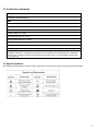
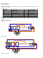
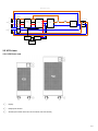
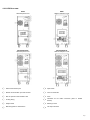
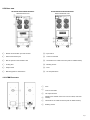
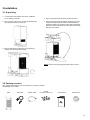
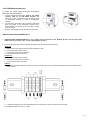
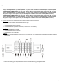
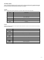
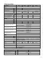
powerquality.eaton.com
Eaton 9E
6-20kVA
Page 1
Contents
1. INTRODUCTION
3
1.1 SAFETY INSTRUCTION
3
1.2 CERTIFICATION STANDARDS
4
1.3 SPECIAL SYMBOLS
4
2.PRESENTATION
5
2.1 MODEL LIST
5
2.2 ELECTRICAL STRUCTURE
5
2.2 UPS VIEWS
6
3.INSTALLATION
9
3.1 UNPACKING
9
3.2 PACKAGE CONTENT
9
3.3 CONNECTION
4.OPERATION
10
16
4.1 DISPLAY AND BUTTONS
16
4.2 OPERATING UPS
18
4.3 CONFIGURATION
19
4.4 TROUBLE SHOOTING
20
4.5 ALARM CODES
21
5.TECHNICAL DATA
22
Page 2
1. Introduction
1.1 Safety instruction
•
The UPS must be installed and maintained exclusively by quailified staff. See installation and operation
instructions before connecting to the supply.
•
The UPS must be installed with an earth connection. It has a high leakage current. The first wire to be
connected is the earth wire, which must be connected to the terminal marked PE (yellow/green).
•
The UPS generates a leakage current of over 3.5 mA. The leakage current of the load should be added to that
of the UPS on the protective earth wire.
•
The UPS needs a neutral connection to work properly. Operation without Neutral may damage the unit.
•
A readily accessible disconnect device shall be incorporated in the building installation wiring for permanently
connected equipment.
•
The UPS generates hazardous electric voltages inside it even when the input and/or battery switches are
open. The inside of the UPS is protected by safety guards that are not to be removed by non-qualified staff. All
installation and maintenance or other operations that entail gaining access to the inside of the UPS require the
use of tools and are to be performed exclusively by qualified staff.
•
The UPS contains an energy source: the batteries. All terminals and sockets may be powered even when the
UPS is not connected to the mains.
•
The total battery voltage is potentially hazardous: it may cause an electric shock. The compartment containing
the batteries is protected by safety guards, which are not to be removed by non-qualified staff. All battery
installation and maintenance operations entail gaining access to the inside of the UPS and require the use of
tools: these operations are to be performed exclusively by qualified staff.
•
The batteries replaced are to be considered as toxic waste and treated accordingly. Dispose of used batteries
according to the instructions. Do not throw the batteries into fire: they could explode. Do not attempt to open
the battery casing: no maintenance work can be done on them. In addition, the electrolyte is hazardous for the
skin and eyes and may be toxic.
•
Risk of explosion if battery is replaced by an incorrect type.
•
Do not turn on the UPS if you see any leaks of liquid or a white powder residue.
•
Make sure that no water, liquid in general and/or other foreign matter gets inside the UPS.
•
Under hazardous conditions, turn off the UPS at the “1/0” main power switch and open all the isolators present
(see the user manual to locate the “1/0” main power switch and the isolators).
•
Do not open the battery fuse holders while the UPS is powering the load from the batteries. An interruption of
the battery DC voltage may cause an electric arc and result in breakage of the equipment and/or fire.
•
The energy required to power the load is provided by the batteries in the event of a power failure. if the battery
protection were open, the load would be powered off.
•
Fuses have to be replaced with the same type if necessary.
•
To connect external battery cabinets, use the expansion cable suggested by the manufacturer in this manual.
Page 3
1.2 Certification Standards
Safety
IEC 62040-1:2008
IEC 60950-1:2005 (Modified)
EMC
Conducted Emission: IEC 62040-2. Category C3
Radiated Emission: IEC 62040-2. Category C3
ESD:IEC 61000-4-2. Contact: Level 2, Air discharge: Level 3
RS:IEC 61000-4-3. Level 3
EFT:IEC/EN 61000-4-4. Level 4
Surge:IEC/EN 61000-4-5. Level 4
CS:IEC/EN 61000-4-6. Level 3
MS:IEC/EN 61000-4-8. Level 3
Voltage Dips, short interruptions and voltage variations:IEC/EN 61000-4-11
Warning: This is a product for commercial and industrial application, in other environment
installation restrictions or additional measures may be needed to prevent disturbances. Additional
curbs may be needed while output wiring length is more than 10m or communication wiring length
is more than 3m.
1.3 Special Symbols
The following are examples of symbols used on the UPS or accessories to show you the important information:
Page 4
2.Presentation
9E series UPS uses ON-LINE double conversion technology, resulting in the highest levels of reliability and maximum
protection for critical loads.
2.1 Model List
Model
Power Ratings
PF
Voltage (Output)
9E6Ki
9E10Ki
9E10KiXL
9E15Ki
9E20Ki
9E20KiXL
9EEBM180
9EEBM240
6kVA/4.8kW
10kVA/8kW Combo
10kVA/8kW Combo
15kVA/12kW Combo
20kVA/16kW Combo
20kVA/16kW Combo
For 9E6Ki
For 9E10Ki, 9E10KiXL
0.8
0.8
0.8
0.8
0.8
0.8
230V (220/240)
230V (220/240)
230V (220/240)
230V (220/240)
230V (220/240)
230V (220/240)
180V
240V
“XL” Model: Model with internal supercharger, and without internal batteries. Other models with internal
batteries
2.2 Electrical structure
9E6Ki
Main power wiring
Bypass
`
Input
Switch
L1
Maintain Switch
Input
filter
INPUT
AC/DC—DC/AC
Output
filter
N
N
Output
Switch
OUTPUT
L
Internal
power
Charger
Battery
9E10Ki, 9E10KiXL
Main power wiring
Bypass
`
Input
Switch
L1
Maintain Switch
L2
Input
filter
INPUT
L3
AC/DC—DC/AC
Output
filter
N
N
OUTPUT
L
Output
Switch
Internal
power
Charger
Battery
9E15Ki, 9E20Ki, 9E20KiXL
Page 5
Main power wiring
Bypass
`
Input
Switch
L1
Maintain Switch
L2
Input
filter
INPUT
L3
AC-DC
DC-AC
Output
filter
N
N
OUTPUT
L
Output
Switch
Internal
power
Charger
Battery
2.2 UPS views
2.2.1 UPS FRONT VIEW
①
Display
③
Wheels (front wheels swivel and can be locked, fixed rear wheels)
②
Multipurpose buttons
Page 6
2.2.2 UPS REAR VIEW
9E6Ki
With backpanel cover
9E6Ki
Without backpanel cover
9E10Ki/9E10KiXL
With backpanel cover
9E10Ki/9E10KiXL
Without backpanel cover
④
USB communication port
⑥
Slot for optional communication card
⑧
Output switch
⑤
RS232 communication port and contacts
⑦
Cooling fan(s)
⑨
Manual bypass for maintenance
⑩
Input switch
⑫
Fuse
⑭
Earthing screws
⑪
Cover for terminals
⑬
Terminals for I/O cable connection (refer to related
section)
⑮
Tie wrap hold-down
Page 7
UPS REAR VIEW
9E15Ki/9E15KiXL/9E20Ki/9E20KiXL
With backpanel cover
④
RS232 communication port and contacts
⑥
Slot for optional communication card
⑧
Output switch
⑤
USB communication port
⑦
Cooling fans
⑨
Manual bypass for maintenance
9E15Ki/9E15KiXL/9E20Ki/9E20KiXL
Without backpanel cover
⑩
Input switch
⑫
Terminals for I/O cable connection (refer to related section)
⑭
Fuse
⑪
Cover for terminals
⑬
Earthing screws
⑮
Tie wrap hold-down
2.2.3 EBM REAR VIEW
①
Fuse
③
Tie wrap hold-down
⑤
Terminals for I/O cable connection (refer to related section)
②
Cover for terminals
④
Wheels (front wheels swivel and can be locked, fixed rear
wheels)
⑥
Earthing screws
Page 8
3.Installation
3.1 Unpacking
1. Cut the straps and carefully remove the cardboard
box by sliding it upwards.
2. Remove the accessory box, the wooden slide and the
top polystyrene foam corner pieces.
4. Open the protective bag and pull it all the way down.
5. Put the previously removed slide on the back part of the
pallet (see figure). Make sure that the slide rests firmly
against the pallet so it remains in place during unloading
operations. Pull the UPS from the front with caution when
sliding it off the pallet.
3. Remove the bottom polyethylene corner pieces by
rotating them as shown in the figure.
NOTE: All parts of the packaging should be kept for future
use.
3.2 Package content
After opening the packaging, it is first necessary to check the contents.
The package must contain:
UPS
USB cable
RS232 cable
Jumper
(15/20kVA models only)
User manual
Software CD
Page 9
3.3 Connection
3.3.1 INSTALLATION REQUIREMENTS
Warning:
Installation must be performed by qualified personnel. The first connection to perform is the protective conductor (earth
cable), which must be connected to the screw marketed
.
The UPS, when inserted in an installation, does not alter the existing neutral (system earthing) arrangements.
A differential switch upstream will also be triggered for a fault occurring downstream of the UPS. In calculating reactivity of this
switch, account must be taken of the leakage current of the UPS (approx. 8 mA) plus that of the load which come together on the
UPS’s earth conductor.
UPS input
Differential switch
Single-phase
Type B or Type A
Three-phase
Type B
The neutral arrangements are altered only if there is an isolating transformer or when the UPS operates with a neutral that is
disconnected upstream.
In any case avoid connecting the output neutral with the input neutral or to the earth as this could damage the UPS.
Reminder : The UPS needs a neutral connection to work properly. Operation without Neutral may damage the unit.
For installation with change in system earthing arrangement or galvanic isolation see below schematic
Fig.3-1 Change in SEA or Galvanic isolation
Notice: It is required to install an external isolating device against current backfeed between Mains input and UPS. After the device
is installed, it must add a warning label with the following wording or the equivalent on the external AC contactor: RISK OF
VOLTAGE BACKFEED. Isolate the UPS before operating on this circuit, then check for hazardous voltage between all terminals.
The current rating of T - AC contactor should be more than 1.3 times of UPS capacity
Single phase input
Three phase input
Fig.3-2 Typical external isolating device installation
Page 10
3.3.2 UPS WIRING CONNECTION
To make the mains power and load connections,
follow the instructions below:
1.
2.
3.
Install a magneto-thermal switch (63A for 6 & 10kVA
versions, 125A for 15 and 20kVA versions) with
intervention curve D upstream of the machine (4 poles
for three-phase versions, 2 poles for single-phase
versions).
The connection terminals to use for the input and output
lines are located on the backpanel. Unscrew the 4
screws located on the sides of the cover (one on each
side, see figure).
Remove the backpanel cover (see figure to the side).
Fig.3-3 Wiring connection
SINGLE-PHASE VERSION (9E6KI ONLY)
2
4. (SINGLE-PHASE CONNECTION 9E6KI): use 3 cables with cross-section 6 mm (EARTH, N and L) for the input, and 3
2
cables with cross-section 6 mm for the output (EARTH, N and L).
5. Connect the wires to the relative terminals, following exactly the instructions given below:
Input line
a - Make sure that the magneto-thermal switch upstream is open.
b - Connect the earth wire to screw A.
c - Connect the neutral wire to terminal 2.
d - Connect the live wire to terminal 1.
Output line
a - Connect the earth wire to screw B.
b - Connect the neutral wire to terminal 3.
c - Connect the live wire to terminal 4.
R.E.P.O.
a - The REPO connection (between terminal 5 and 6) is normally open. For more information please refer to the REPO section
of this manual
Fig.3-4 6K terminal view
6. Tighten the terminals well, close the backpanel cover and secure it with the screws taken out earlier.
The suggested tighten force is 1.2~1.6Nm.
Page 11
COMBO VERSION
SINGLE-PHASE CONNECTION
2
4. (SINGLE-PHASE CONNECTION 9E10KI, 9E10KIXL): use 3 cables of cross-section 10 mm (EARTH, N and L) for the
2
input, and 3 cables of cross-section 10 mm for the output(EARTH, N and L).
2
(SINGLE-PHASE CONNECTION 9E15KI, 9E15KIXL): use 3 cables of cross-section 16 mm (EARTH, N and L) for the
2
input, and 3 cables of cross-section 16 mm for the output(EARTH, N and L).
2
(SINGLE-PHASE CONNECTION 9E20KI, 9E20KIXL): use 3 cables of cross-section 25 mm (EARTH, N and L) for the
2
input, and 3 cables of cross-section 25 mm for the output(EARTH, N and L).
5. Short-circuit the input terminals (1, 2 and 3) with the jumper provided in the accessories kit. Connect the wires to the respective
terminals, following exactly the instructions below:
Input line
a - Ensure that the upstream magneto-thermal switch is open.
b - Connect the earth wire to screw A.
c - Connect the neutral wire to terminal 4.
d - Connect the live wire to terminal 1.
Output line
a - Connect the earth wire to screw B.
b - Connect the neutral wire to terminal 5.
c - Connect the live wire to terminal 6.
R.E.P.O.
a - The REPO connection (between terminal 5 and 6) is normally open. For more information please refer to the REPO section
of this manual
JUMPER
Fig.3-5 10~20K single phase input terminal view
6. Tighten the terminals well, close the backpanel cover and secure it with the screws taken out earlier.
For 10 to 15kVA the suggested tighten force is 1.2~1.6Nm. For 20kVA, the suggested tighten force is 2.5~3 Nm.
Page 12
THREE-PHASE CONNECTION
2
1. (THREE-PHASE CONNECTION 9E10KI, 9E10KIXL): Use 2 cables of cross-section 4 mm (L2 and L3) and 3 with cross2
section 10 mm (EARTH, N, L1) for the input (N.B.: L1 and N are of greater cross-section because in bypass operation
2
they have to carry all of the input current). For the output use 3 cables of cross-section 10 mm (EARTH, N and L).
2
(THREE-PHASE CONNECTION 9E15KI, 9E15KIXL): Use 2 cables of cross-section 4 mm (L2 and L3) and 3 of cross2
section 16 mm (EARTH, N, L1) for the input (N.B.: L1 and N are of greater cross-section because in bypass operation
2
they have to carry all of the input current). For the output use 3 cables of cross-section 16 mm (EARTH, N and L).
2
(THREE-PHASE CONNECTION 9E20KI, 9E20KIXL): Use 2 cables of cross-section 6 mm (L2 and L3) and 3 of cross2
section 25 mm (EARTH, N, L1) for the input (N.B.: L1 and N are of greater cross-section because in bypass operation
2
they have to carry all of the input current). For the output use 3 cables of cross-section 25 mm (EARTH, N and L).
2. Connect the wires to the respective terminals, following exactly the instructions below:
Input line
a - Ensure that the upstream magneto-thermal switch is open.
b - Connect the earth wire to screw A.
c - Connect the neutral wire to terminal 4.
d - Connect the wires of the phases to terminals 1, 2 and 3 (for L1 use red wire).
Output line
a - Connect the earth wire to screw B.
b - Connect the neutral wire to terminal 5.
c - Connect the live wire to terminal 6.
R.E.P.O.
a - The REPO connection (between terminal 5 and 6) is normally open. For more information please refer to the REPO section of
this manual
Fig.3-6 10~20K three phase input terminal view
3.
4.
3. Tighten the terminals well, close the backpanel cover and secure it with the screws taken out earlier.
For 10 to 15kVA the suggested tighten force is 1.2~1.6Nm. For 20kVA, the suggested tighten force is 2.5~3 Nm.
Page 13
R.E.P.O.
The terminal block on the back of the UPS also implements the R.E.P.O. (Remote Emergency Power Off) function that can be used
to shut off the UPS remotely in case of an emergency.
For installation, connect to the device's normally open contact .
In case of an emergency, if the stop device is used, the REPO control is closed and the UPS goes into stand-by mode and the load
is completely disconnected.
Attention: before restarting the UPS, reset the stop device.
The circuitry of the remote control terminal board is self-powered with SELV circuits. Therefore, an external voltage supply is not
required. When a contact is closed, a maximum current of 15mA circulates.
All connections with the remote control terminal board are made through a cable which guarantees a double insulation connection.
If you would like to bring the R.E.P.O. control outside, unscrew the two screws securing the lower part of the backpanel cover and
remove it (as indicated in the section “Connections”). Then, proceed as follows:
2
1. Use a 2x0.75mm cable to make the connection with the R.E.P.O. terminals.
2. Insert the screw driver in the square hole and press down to make the round hole terminal open. Then insert the wire into the
round hole. Then pull out the screw driver. Connect the two wires of the cable to terminals 5 and 6 (for version 9E6Ki), 7 and 8
(for versions 9E10Ki, 9E10KiXL, 9E15Ki, 9E15KiXL, 9E20Ki, 9E20KiXL) to be able to remotely shut off the UPS.
9E6Ki
9E10Ki, 9E10KiXL, 9E15Ki, 9E15KiXL, 9E20Ki,
9E20KiXL
Fig.3-7 EPO terminal connection
3. Close the backpanel cover and secure it with the screws taken out earlier.
Page 14
3.3.3 EBM WIRING CONNECTION
It is possible to connect more than one EBM in order to achieve any level of autonomy without mains power. Connect any Battery
Boxes in a cascade as shown in the figure below:
2
1. CONNECTION: Use 3 cables with 10 mm section (Earth, +, N and -)
2. Connect the wires to the relative terminals, following exactly the instructions given below:
For 9E6Ki, 9E10Ki, 9E10KiXL
aMake sure that the fuse holder of the external battery box is open.
bConnect the earth (PE) wire to EBM’s earth (PE) screw
cConnect the positive (+) branch wire to EBM’s positive (+) terminal.
dConnect the negative (-) branch wire to EBM’s negative (-) terminal.
The suggested tighten force is 1.6Nm. (Detailed wiring diagram see fig 3-9~10)
Fig.3-8 EBM terminal view (Fuse for 9E6Ki,
9E10Ki, 9E10KiXLwithout Neutral)
Versions 9E6Ki, 9E10Ki, 9E10KiXL
Fig.3-9 EBM terminal connection for 9E6Ki,
9E10Ki, 9E10KiXL With Single EBM
Fig.3-10 EBM terminal connection for 9E6Ki,
9E10Ki, 9E10KiXL With Mutliple EBM
Note: For 9E15Ki, 9E20Ki, 9E20KiXL EBM wiring connection, you should check the 9EEBM manual in EBM
package.
Page 15
4.OPERATION
4.1 Display and Buttons
Fig. 4-1 Control Panel
The following tables shows the buttons, LCD indicator and LED indicator status and description:
Table 4-1 Control Buttons Functions
The Button
Function
Turn on
Turn off
Transfer
Illustration
If the UPS is in standby or bypass mode, press >2s, the buzzer will beep once, then the UPS
system will be turned on.
If the UPS is in line, battery, HE or battery test mode, press >3s, the buzzer will beep once, then
the UPS will be turned off.
If the UPS is in fault mode, and the fault cause has disappeared, press >2s, the buzzer will beep
once, fault will be cleared and UPS will turn to standby mode.
Battery test on line mode,Press the button >2s
Function key
Mute: Press the button >2s
Down to next page: Press the button<200ms
Table 4-2 LED indicator
LED name
Colour
Line
Description
Green
It indicates the utility is normal
Battery
Yellow
It indicates the input is connected with battery, and the
input power is supplied from the battery.
Bypass
Yellow
It indicates the UPS is in bypass mode, the load current is
directly supplied from the utility power
Inverter
Green
It indicates that the inverter is OK and the load is supplied
from the inverter.
Note: After UPS power on, all LEDs will be lightened for 2 seconds, and then turn to normal status. When UPS is turning on, 4
LEDs will be lightened one by one until the UPS is turned on successfully.
LED
No Output mode
Bypass mode
Line mode
Line
Battery
⊙
●
Bypass
●
●
●
●
Battery mode
●
Fault mode
□
Warning
□
⊙:Utility is normal
●: Lightened constantly
★: Flashing every 4s
◇: Depended on the fault status
□: Depend on the original display
●
★
Battery test mode
Inverter
◇
□
□
□
Page 16
Table 4-3 Buzzer
Priority
UPS condition
Buzzer
1
UPS fault and failure
Continuous
2
Normal mode
No beep
Battery/battery test mode
One beep per 4 sec
3
(One beep per 1s when battery low)
4
Bypass mode
One beep per 2 minutes
5
Overload
One beep per 500ms
6
Other alarm
One beep per 1s
7
Manual bypass
One beep per 1s
Note: buzzer alarm can be enable/disable by function button, if buzzer alarm is disabled, all present alarm is muted
except that the button press still has a tick beep. Buzzer alarm will be enabled automatically once new alarm arises.
Interface
In order to make sure all segments are OK, LCD begins to do self-test after power on. During self-test, all the segments
will be lighted for 2 seconds, then the LCD will turn to normal display status.
Fig. 4-2 The default LCD display
Icon
Icon name
Description
Measurements
Display values, eg: voltage, frequency,
load percentage, etc.
DC Voltage
Percentage
Output
Input
Battery voltage
The percentage, eg: Load percentage and
battery capacity percentage
It indicates information for output.
It indicates information for input.
Load
It indicates information for load.
Battery
It indicates information for battery.
Load level
It indicates the load level. Load border will
flash if the load is overload.
Battery level
It indicates the battery capacity. Battery
border will flash if the battery is low.
It indicates warnings or UPS Fault .
Warning/Fault
If it is a warning, the icon will flash; if it is a
fault, the icon will be lighted constantly.
Page 17
4.2 Operating UPS
Notice: Please switch off the connected loads first before turning on the UPS, and switch on the loads one by
one after the UPS is turned on. Switch off all of the connected loads before turning off the UPS.
Notice: Power on for the first time
1. Close the magnetothermic switch located upstream of the UPS.
2. Close the input and output switches and insert the battery fuses (if any) located on the back of the UPS’s
backpack.
4.2.1 TURNING ON UPS WITH MAINS
Check that all connections are correct. Check the breaker of external battery pack is in “ON” position.
Set input breaker in “ON” position. At this time the fan begins to rotate. By pressing
button continuously for
more than 2 second, the buzzer will beep once, UPS starts to turn on.
A few seconds later, the UPS turns into Line mode. If the mains power is abnormal, the UPS will transfer to
Battery mode without output interruption of the UPS.
4.2.2 TURNING ON UPS WITHOUT MAINS
Check that all connections are correct. Check the breaker of external battery pack is in “ON” position.
By pressing
button continuously for more than 2s, the buzzer will beep once, UPS starts to turn on.
A few seconds later, the UPS turns into Battery mode. If the mains power comes back, the UPS will transfer to
Line mode without output interruption of the UPS.
4.2.3 TURNING OFF UPS WITH MAINS
To turn off the inverter of UPS press
button continuously for more than 3s and the buzzer beep once.
The UPS will turn into standby mode.
Cut off the mains power supply.
A few seconds later, LCD display shuts down.
4.2.4 TURNING OFF UPS WITHOUT MAINS
To power off the UPS press
button continuously for more than 3s, and the buzzer beep once. The UPS will
cut off the output.
A few seconds later, LCD shuts down and no voltage is available from the UPS output.
4.2.5 TRANSFER TO BYPASS
To transfer the UPS in internal bypass mode, press on/off button and test button at the same time for more
than 4 seconds.
To transfer the UPS back to normal mode, press on/off button and test button at the same time for more than 4
seconds.
4.2.6 TRANSFER TO MAINTENANCE BYPASS
To transfer the UPS in maintenance bypass mode, switch on the maintenance switch. And then the UPS will
transfer to maintenance bypass mode. Switch off the input and output switch before doing maintenance on the
UPS.
To transfer the UPS back to normal mode, switch on the input and output switch and then switch off the
maintenance switch. Then turn on the UPS following “Turning on UPS” steps.
Page 18
4.3 Configuration
4.3.1
COMMUNICATION PORTS
On the back of the UPS (see UPS Views), the following communication ports are present: RS232 connector, USB connector, Slot
for optional connectivity cards
RS232 or USB communication ports
The RS232 and USB communication ports cannot operate simultaneously.
1. Connect the RS232 or USB communication cable to the serial or USB port on the computer.
2. Connect the other end of the communication cable to the RS232 or USB communication port on the UPS.
The UPS can now communicate with EATON power management software
Connectivity Cards
The UPS is equipped with an expansion slot for optional Connectivity
Cards (see figure on right).
It is not necessary to shutdown the UPS before installing a
communication card.
1. Remove the slot cover secured by screws.
2. Insert the communication card in the slot.
3. Secure the card cover with the 2 screws
Connectivity cards allow the UPS to communicate in a variety of networking environments and with
different types of devices.
•
•
•
4.3.2
Network-MS card - has SNMP and HTTP capabilities as well as monitoring through a Web browser
interface; connects to Ethernet network. In addition, a Environmental Monitoring Probe can be atta- ched
to obtain humidity, temperature, smoke alarm, and security information.
Modbus-MS card - has connection to Modbus protocol in addition to network management.
Relay-MS card - has isolated dry contact (Form-C) relay outputs for UPS status: Utility failure, Battery low,
UPS alarm/OK, or on Bypass.
EATON INTELLIGENT POWER SOFTWARE SUITE
Each 9E UPS ships with Eaton Intelligent Power Software suite. To begin installing, see the instructions
accompanying the Software suite CD.
Eaton Software suite provides up-to-date graphics of UPS power and system data and power flow.
It also gives you a complete record of critical power events, and it notifies you of important UPS or power
information.
If there is a power outage and the 9E UPS battery power becomes low, Eaton Software suite can automatically shut down
your computer system to protect your data before the UPS shutdown occurs.
Page 19
4.4 Trouble shooting
PROBLEM
THE DISPLAY DOES
NOT LIGHT UP
POSSIBLE CAUSE
SOLUTION
INPUT SWITCH OPEN
Close the input switch located on the back of the
UPS.
MAIN CONNECTION CABLE
MISSING
Check that the power cable is connected correctly.
NO MAINS VOLTAGE
(BLACKOUT)
Check that the power reaches the UPS
UPSTREAM THERMAL
PROTECTION TRIP
Reset the thermal protection.
CAUTION: Check that there is no output overload to
the UPS.
THE DISPLAY IS ON BUT
THE LOAD IS NOT
THE UPS IS IN Standby mode
POWERED
Press the “ON” button on the front panel to power the
loads.
THE UPS IS OPERATING
FROM THE BATTERY
DESPITE THE
PRESENCE OF MAINS
VOLTAGE
THE INPUT VOLTAGE IS
OUTSIDE THE PERMITTED
TOLERANCE RANGE FOR
MAINS OPERATION
Problem with the mains. Wait until the input mains
voltage returns within the tolerance range. The UPS
will automatically return to mains operation.
THE BUZZER SOUNDS
CONTINUOUSLY AND
THE DISPLAY SHOWS
ONE OF THE
FOLLOWING CODES:
A80E, A810, F808
THE LOAD APPLIED TO THE
UPS IS TOO HIGH
Reduce the load to within the threshold of 100% (or
user threshold in the case of code A80E).
If the display shows an Fault:
remove the load and switch the UPS off and back on
again.
THE DISPLAY SHOWS
THE FOLLOW CODE:
A60D
BATTERIES MISSING OR
BATTERY BOX MISSING OR
NOT CONNECTED
Check that the Battery Box is inserted and connected
to the UPS correctly.
THE BUZZER SOUNDS
CONTINUOUSLY AND
THE DISPLAY SHOWS
ONE OF THE
FOLLOWING CODES:
A004 F004
THE TEMPERATURE INSIDE
THE UPS IS TOO HIGH
Check that the temperature of the environment in
which the UPS is located does not exceed 40°C.
THE BUZZER SOUNDS
CONTINUOUSLY AND
THE DISPLAY SHOWS
ONE OF THE
FOLLOWING CODES:
F805
THERE IS A FAULT ON ONE
OR MORE OF THE LOADS
POWERED BY THE UPS
Disconnect all the utilities, switch the UPS off and
back on again, reconnect the utilities one at a time to
identify which one is faulty.
THE BUZZER SOUNDS
CONTINUOUSLY AND
THE DISPLAY SHOWS
ONE OF THE
FOLLOWING CODES:
F704, F70D,F70C,F302,
F303,F305,F300,F301,F3
04, F002
THE DISPLAY SHOWS
THE CODE: A900
If possible, disconnect the power to the load, switch
THE UPS IS MALFUNCTIONING the UPS off and back on again; if the problem occurs
again, call the support centre.
THE MAINTENANCE BYPASS
FUNCTION IS ACTIVE
To take the UPS out of the maintenance bypass
function, open the manual bypass switch on the back
of the UPS.
Page 20
4.5 Alarm codes
Using a sophisticated self-diagnosis system, the UPS is able to check its own status and any anomalies and/or faults
which may occur during normal operation and display them on the display panel. If there is a problem, the UPS signals
the event by showing the code and the type of active alarm on the display.
ALARMS
“Minor” problems which reduce performance or prevent certain functions from being used.
CODE
DESCRIPTION
A007
Fans blocked
A107
Cable connection error
A10A
Unbalanced input voltages (three-phase input)
A806
E.P.O control active
A80E
Overload: load > 105%
A810
Load percentage greater than the user threshold set
A60D
Batteries missing or Battery Box missing or not connected
A802
Low battery
FAULTS
Faults are normally preceded by an alarm signal and their scale leads to the power-off of the inverter and the load being
powered by the bypass line.
CODE
DESCRIPTION
F002
F004
F302 F303
F300 F301
F304
F305
F70D
F805
F704
F70C
F808
F811
UPS Fault
Dissipator over temperature
Capacitor bank undervoltage
Capacitor bank overvoltage
Unbalanced capacitor bank
Failed capacitor bank soft start
Inverter overvoltage
Short circuit
Failed inverter soft start
Inverter undervoltage
Output overload fault
Negative output power
Page 21
5.Technical data
UPS MODELS
9E10Ki,
9E10KiXL
9E6Ki
9E20Ki,
9E20KiXL
9E15Ki
INPUT
Nominal voltage
[Vac]
220 - 230 - 240
220 - 230 – 240 / 380 – 400 - 415
Maximum operating voltage
[Vac]
276
276 / 478
Nominal frequency
Nominal current
BATTERY
Recharge time (standard versions)
Expandability and nominal
voltage of the Battery Box
Charging current
(for XL versions only)
[Hz]
50 - 60
26
[A]
41 / 16
(42 / 20,5 XL)
82 / 28
(83 / 29,5 XL)
62 / 22
< 8h for 90% of the charge
[h]
180Vdc
240Vdc
240 + 240Vdc
240 + 240Vdc
Not applicable
4,4A
5A
5A
OUTPUT
Nominal voltage
[Vac]
Selectable: 220/230/240
Frequency
[Hz]
Selectable: 50, 60 or auto sensing
Nominal power
[VA]
Nominal power
[W]
6000
10000
4800
Bypass line available:
8000
Overload: 105% < load < 110%
15000
20000
12000
16000
activates the bypass after 5 min, then
continues to work
Bypass line not available:
locks after 5 min
Bypass line available:
activates the bypass after 1 min, then
locks after 1 min
Bypass line not available:
locks after 1 min
Bypass line available:
activates the bypass after 10 s, then
locks after 10 s
Bypass line not available:
locks after 10 s
Bypass line available:
activates the bypass after 100 ms, then
locks after 1 s
Bypass line not available:
locks after 1 s
Overload: 110% < load < 130%
Overload: 130% < load < 150%
Overload load > 150%
OTHER
Leakage current to earth
Ambient temperature
[mA]
< 8mA
[°C]
0 – 40
Humidity
< 95% without condensation
Batteries deep discharge - overcurrent - short circuit - overvoltage undervoltage - circuit breaker
Protection devices
Dimensions W x D x H
Weight
[mm]
262 x 613x 709
[kg]
350 x 706 x 818
85
(34 XL)
65
153
(48 XL)
142
0 oC to 40 oC
Operating Temperature
Operating humidity
0-95% no condensing
Altitude
Up to 1,000 meters above sea level with 10% derating per 1000m
Storage temperature
-15oC to 60oC without batteries
0~35°C with batteries
EBM
Nominal battery voltage
[Vdc]
Dimensions W x D x H
[mm]
Weight
[kg]
180VDC 9Ah
240VDC 9Ah
180Vdc
240Vdc
262 x 580 x 709
130
148
Page 22