1
MicroSCADA Pro
SYS 600 9.2
System Configuration
Configuration Manual
1MRS756112
Issued: 27.07.2007
Version: A/27.07.2007
MicroSCADA Pro
SYS 600 9.2
System Configuration
Configuration Manual
Contents
Copyrights ................................................................................. 7
1. Introduction..............................................................9
1.1.
1.2.
1.3.
1.4.
1.5.
1.6.
This manual.............................................................. 9
Use of symbols ......................................................... 9
Intended audience ..................................................... 9
Product documentation ............................................. 10
Document conventions ............................................. 10
Document revisions...................................................11
2. Functional overview of SYS 600 ............................... 13
2.1.
2.2.
2.3.
2.4.
2.5.
2.6.
2.7.
2.8.
2.9.
2.10.
2.11.
2.12.
2.13.
2.14.
System server .........................................................
Workplaces.............................................................
Process communication ............................................
System self supervision ............................................
Event handling ........................................................
Alarm handling ........................................................
Communication gateway ...........................................
Peripheral equipment ...............................................
2.8.1. Printers ......................................................
2.8.2. Alarm output I/O ..........................................
Time handling .........................................................
2.9.1. Time synchronization....................................
Mapping devices......................................................
Redundancy ...........................................................
Mirroring.................................................................
OPC connectivity .....................................................
Capacity and performance scalability ..........................
13
15
16
17
18
18
19
20
21
21
22
23
24
24
25
25
26
3. Configuration.......................................................... 29
3.1. Configuring system server .........................................
3.1.1. Hardware and operating system .....................
3.1.2. Systems (SYS)............................................
3.1.2.1. System configuration......................
3.1.2.2. Memory configuration .....................
3.1.3. Applications (APL) .......................................
3.1.3.1. Configuring APL objects .................
3.1.3.2. Mapping devices ...........................
3.1.3.3. Tuning memory parameters.............
3.1.3.4. Adding applications........................
3.1.3.5. Removing applications ...................
3.2. Configuring workplaces.............................................
29
30
31
32
37
39
39
40
41
41
42
42
3
SYS 600 9.2
MicroSCADA Pro
System Configuration
1MRS756112
Configuration Manual
3.2.1.
3.2.2.
3.3.
3.4.
3.5.
3.6.
3.7.
3.8.
4
Windows terminal server ............................... 42
Citrix MetaFrame Application Server ............... 45
3.2.2.1. Verifying client connections ............. 47
3.2.3. WinnConn XP Server/BeTwin ........................ 48
3.2.4. Defining MON objects................................... 49
3.2.5. Monitor Pro Configuration.............................. 50
Configuring process communication ............................ 55
3.3.1. Configuring communication system objects in
base system ............................................... 56
3.3.2. Configuring process communication units ........ 57
3.3.2.1. Configuring PC-NET ...................... 58
3.3.2.2. Configuring CDC-II Slave................ 63
3.3.2.3. Configuring Modbus Slave .............. 64
3.3.2.4. Configuring CPI-connected
applications .................................. 64
3.3.2.5. Selected configuration examples
for PC-NET .................................. 64
3.3.3. Distributed process communication units ......... 78
3.3.3.1. Distributed PC-NETs ...................... 78
Configuring communication gateway ........................... 80
3.4.1. SYS_BASCON.com modifications .................. 81
3.4.2. Gateway license .......................................... 81
Configuring peripheral equipment ............................... 82
3.5.1. Configuring printers ...................................... 82
3.5.2. Configuring I/O adapter cards ........................ 83
Configuring time handling.......................................... 85
3.6.1. Configuring time synchronization .................... 85
3.6.1.1. Configuring external clocks ............. 87
Configuring networks................................................ 87
3.7.1. Configuring Local Area networks (LAN) ........... 89
3.7.2. Communicating between applications .............. 90
3.7.2.1. Local applications.......................... 91
3.7.2.2. Applications in separate base
systems ....................................... 92
Configuring redundancy ............................................ 94
3.8.1. Hot stand-by base systems ........................... 94
3.8.1.1. Configuring hot stand-by systems..... 94
3.8.1.2. SYS_BASCON.HSB ...................... 95
3.8.1.3. Watchdog application ....................101
3.8.1.4. Shadowing ..................................103
3.8.2. Hot stand-by with OPC client and servers .......104
3.8.2.1. Configuring IEC 61850 OPC Server..105
3.8.2.2. Configuring IEC 61850 OPC Client..105
1MRS756112
MicroSCADA Pro
SYS 600 9.2
System Configuration
Configuration Manual
3.8.2.3.
Configuring External OPC Data
Access Client...............................105
3.8.2.4. Configuring IEC 61850 process
devices .......................................108
3.8.3. Configuring redundant IEC 60870-5-104
slaves .......................................................108
3.8.4. Configuring redundant RP 570 slaves ............109
3.8.5. Configuring redundant IEC 60870-5-101
slaves ....................................................... 110
3.8.6. Redundant gateways................................... 111
3.9. Configuring mirroring ............................................... 112
3.9.1. Station mapping ......................................... 114
3.9.2. Process messages...................................... 114
3.9.3. Process commands..................................... 115
3.9.4. System object (STA:S) communication ........... 115
3.9.5. System messages ...................................... 115
3.9.6. Subscriptions ............................................. 116
3.9.7. Buffering and communication breaks.............. 117
3.9.8. Hot stand-by .............................................. 118
3.9.9. Disabling mirroring ...................................... 119
3.9.10. Application events....................................... 119
3.9.11. Configuration examples ...............................121
3.9.11.1. Example 1: One host, one image ....122
3.9.11.2. Example 2: Two hosts, redundant
image .........................................124
3.9.11.3. Example 3: Station mapping in a
mirroring system...........................126
3.9.11.4. Example 4: Local mirroring.............128
3.9.11.5. Example 5: Hierarchical mirroring....129
4. Configuration tools ............................................... 131
4.1. System Configuration Tool........................................131
4.1.1. Starting System Configuration Tool ................131
4.1.2. Handling objects and attributes .....................132
4.1.2.1. Changing attribute values ..............132
4.1.2.2. NET Node station address .............134
4.1.3. Saving configurations ..................................134
4.1.4. Creating a new configuration ........................134
4.1.4.1. Adding new objects ......................135
4.1.4.2. Deleting objects ...........................136
4.1.4.3. Adding a redundant line.................137
4.1.4.4. Deleting a redundant line ...............138
4.1.5. Configuring dial-up ......................................138
4.1.6. Saving as a default configuration...................139
4.1.7. Online configuration ....................................140
5
SYS 600 9.2
MicroSCADA Pro
System Configuration
1MRS756112
Configuration Manual
4.1.7.1. Loading online configuration...........140
4.1.7.2. Saving online configuration ............142
4.1.8. Taking configuration in use and out of use ......142
4.1.9. Reallocating stations ...................................143
4.1.9.1. Cutting and copying stations ..........143
4.1.9.2. Pasting stations............................144
4.1.10. Previewing.................................................145
4.1.11. User-defined programs ................................145
4.1.12. Sending general object handling command .....146
4.1.13. Defining general environment definitions .........147
4.1.14. System monitoring ......................................148
4.1.14.1. Supervision log ............................149
4.1.14.2. Classic monitor supervision............150
4.1.15. Signal engineering ......................................150
4.1.15.1. Indicator for signal information ........151
4.1.15.2. REX, LMK and SPA stations ..........152
4.1.15.3. Topic configuration for PLC stations..152
4.1.15.4. Configuring data points for DNP
stations.......................................155
4.1.15.5. Configuring memory areas for STA
stations.......................................158
4.2. Base System Tool...................................................162
5. Abbreviations ....................................................... 163
6
1MRS756112
MicroSCADA Pro
SYS 600 9.2
System Configuration
Configuration Manual
Copyrights
The information in this document is subject to change without notice and should not
be construed as a commitment by ABB Oy. ABB Oy assumes no responsibility for
any errors that may appear in this document.
In no event shall ABB Oy be liable for direct, indirect, special, incidental or
consequential damages of any nature or kind arising from the use of this document,
nor shall ABB Oy be liable for incidental or consequential damages arising from
use of any software or hardware described in this document.
This document and parts thereof must not be reproduced or copied without written
permission from ABB Oy, and the contents thereof must not be imparted to a third
party nor used for any unauthorized purpose.
The software or hardware described in this document is furnished under a license
and may be used, copied, or disclosed only in accordance with the terms of such
license.
© Copyright 2007 ABB. All rights reserved.
Trademarks
ABB is a registered trademark of ABB Group. All other brand or product names
mentioned in this document may be trademarks or registered trademarks of their
respective holders.
Guarantee
Please inquire about the terms of guarantee from your nearest ABB representative.
7
8
1MRS756112
MicroSCADA Pro
SYS 600 9.2
System Configuration
Configuration Manual
1.
Introduction
1.1.
This manual
This manual provides thorough information on the various configuration settings
that you have to make in order to take your SYS 600 system into use, focusing on
describing how to configure SYS 600 for an IEC 61850 system. The manual also
describes how to use the configuration tools.
1.2.
Use of symbols
This publication includes the following icons that point out safety-related conditions
or other important information:
The caution icon indicates important information or warning related to
the concept discussed in the text. It might indicate the presence of a
hazard which could result in corruption of software or damage to
equipment or property.
The information icon alerts the reader to relevant facts and conditions.
It should be understood that operation of damaged equipment could, under certain
operational conditions, result in degraded process performance leading to
information or property loss. Therefore, comply fully with all notices.
1.3.
Intended audience
This manual is intended for engineers to support configuration and engineering of
systems and/or applications.
9
MicroSCADA Pro
System Configuration
SYS 600 9.2
1MRS756112
Configuration Manual
1.4.
Product documentation
Name of the document
Document ID
SYS 600 Application Design
1MRS756170
SYS 600 Application Objects
1MRS756175
SYS 600 Communication Programming Interface (CPI)
1MRS756127
SYS 600 Connecting LONWORKS Devices
1MRS756154
SYS 600 IEC 60870-5-101 Slave Protocol
1MRS756159
SYS 600 IEC 60870-5-104 Slave Protocol
1MRS756162
SYS 600 IEC 61850 System Design
1MRS756119
SYS 600 OPC Data Access Client
1MRS756163
SYS 600 Programming Language SCIL
1MRS756176
SYS 600 System Objects
1MRS756177
IEC 61850 Master Protocol (OPC)
1MRS756230
LIB 500 *4.2. Operation Manual
1MRS755359
RER 111 Technical Reference Manual
1MRS750104-MUM
SPA-ZC 400, SPA to IEC 61850 Gateway, Installation and
Commissioning Manual
1MRS755347
Other related documents:
*
*
1.5.
Microsoft Windows Server 2003 Terminal Server licensing manual
MMC500_TS.CMD in the Microsoft Windows Server 2003 Terminal Server
installation Manual
Document conventions
The following conventions are used for the presentation of material:
*
*
*
*
*
*
*
*
*
*
10
The words in names of screen elements (for example, the title in the title bar of a
dialog, the label for a field of a dialog box) are initially capitalized.
Capital letters are used for the name of a keyboard key if it is labeled on the
keyboard. For example, press the CTRL key. Although the Enter and Shift keys
are not labeled they are written in capital letters, e.g. press ENTER.
Lowercase letters are used for the name of a keyboard key that is not labeled on
the keyboard. For example, the space bar, comma key and so on.
Press CTRL+C indicates that you must hold down the CTRL key while pressing
the C key (to copy a selected object in this case).
Press ALT E C indicates that you press and release each key in sequence (to copy
a selected object in this case).
The names of push and toggle buttons are boldfaced. For example, click OK.
The names of menus and menu items are boldfaced. For example, the File menu.
The following convention is used for menu operations: Menu Name > Menu
Item > Cascaded Menu Item. For example: select File > Open > New Project.
The Start menu name always refers to the Start menu on the Windows Task Bar.
System prompts/messages and user responses/input are shown in the Courier
font. For example, if you enter a value out of range, the following message is
displayed: Entered value is not valid.
1MRS756112
MicroSCADA Pro
SYS 600 9.2
System Configuration
Configuration Manual
You may be told to enter the string MIF349 in a field. The string is shown as
follows in the procedure: MIF349
*
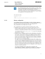
1.6.
Variables are shown using lowercase letters: sequence name
Document revisions
Version
Software revision
number
Date
A
9.2
27.07.2007
History
Document created
11
12
1MRS756112
MicroSCADA Pro
SYS 600 9.2
System Configuration
Configuration Manual
2.
Functional overview of SYS 600
For a MicroSCADA Pro system to operate properly, it must be configured for the
special environment in which it is operating. MicroSCADA Pro contains
configuration software in the form of objects and data files. The configuration
software defines:
*
*
*
*
*
Nodes
Applications
Device connections
Communication properties
Memory capacities, destination addresses, and so on.
The System Configuration Tool manages the configuration of the base system and
the PC-NET. In the current version, the following base system and system objects
can be created and configured:
*
*
*
*
*
Integrated link to the PC-NET
PC-NET
LonTalk (LON), IEC, RP 570, RP 571, LCU500, DNP 3.0, Modbus, SPA,
ADLP180M and IEC 61107 protocol lines
REX, LMK, IEC, SPI, LCU500, DNP, PLC, and SPA Stations
LON Clock Master and LON Star Coupler
A MicroSCADA Pro system is composed of:
*
*
*
*
One or more base systems
Process communication system
Operator workplaces
Peripheral devices
In addition, it can utilize local area networks (LANs).
2.1.
System server
The MicroSCADA Pro base systems are control centres that contain the supervisory
control and monitoring functions of MicroSCADA Pro. The tasks of a base system
are to collect all process-related data from the stations into the process database,
distribute the information and to send control commands via the NET
communication units.
Each base system is composed of a base system computer including base system
software. The base system computer is a standard PC running the Windows
operating system. The MicroSCADA Pro base system software is composed of:
*
*
*
*
*
MicroSCADA Pro kernel
Number of facility programs
Engineering and system handling tools
Configuration software
Application software
13
SYS 600 9.2
MicroSCADA Pro
System Configuration
1MRS756112
Configuration Manual
The MicroSCADA Pro kernel, as well as most of the engineering and system
handling tools, is the same in all base systems independent of the application area or
the extent of use.
The configuration software is specified for the base system in question and adapted
to the device configuration of the entire MicroSCADA Pro system.
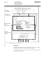
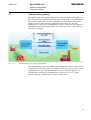
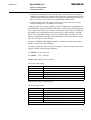
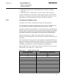
A base system can contain one or more applications as shown in Fig. 2.1.-1. An
application includes application software and databases. The application software
specifies the functions of the MicroSCADA Pro base system as a supervisory
control system. The application software is adapted for a certain process and for the
user’s needs regarding the level of information, user interface, control operations,
and so on. A base system can run several applications in parallel.
Local area networks (LAN) can be used for connecting base systems with other base
systems and base systems with workplaces.
14
1MRS756112
MicroSCADA Pro
SYS 600 9.2
System Configuration
Configuration Manual
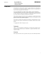
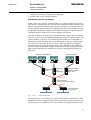
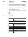
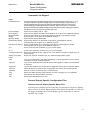
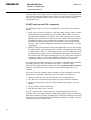
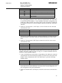
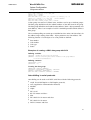
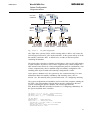
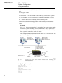
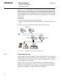
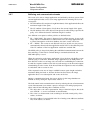
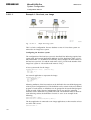
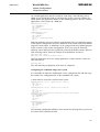
MicroSCADA System Overview
Operator
Workstations
PCs containing workstation programs
Local Area
Network (LAN)
Operator workstation
Printers
Alarm unit
Base System computer
Base Systems
and
Peripherals
Base System Software
- Kernel (main program)
- Engineering tools
- Base System Configuration
- Application software
Application Software
- Pictures, dialogs
- Report data
- Process data
- Control programs, etc.
DCP-NET units:
Communication card
- Communication program
incl. conf parameters
-
Process
Communication
System
- NET program
- Configuration file
Communication frontends
- Communication card
- Communication program
incl. conf parameters
System_overview.eps
A051599
Fig. 2.1.-1
2.2.
MicroSCADA Pro main system components
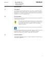
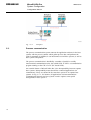
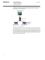
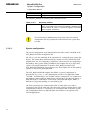
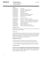
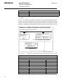
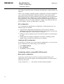
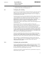
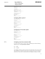
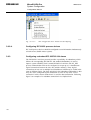
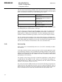
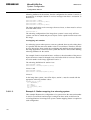
Workplaces
A Workplace is a computer that has a remote desktop session to the server using
Microsoft Terminal Services or a Citrix remote session solution.
The workplaces are connected via LAN or via remote connections, which use the
operating system feature RAS.
15
SYS 600 9.2
MicroSCADA Pro
System Configuration
1MRS756112
Configuration Manual
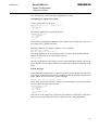
A070735
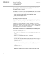
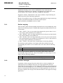
Fig. 2.2.-1
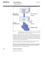
2.3.
Workplace
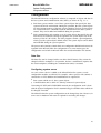
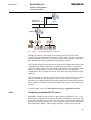
Process communication
The process communication system connects the application software in the base
systems with the process stations which gather process data, and performs the
control commands. In addition, it can interconnect several base systems, as well as
base systems and printers.
The process communication is handled by a number of parallel or serially
interconnected communication units, also called NETs. A NET is a communication
program running on the CPU of a PC (PC based NETs).
An essential feature of MicroSCADA Pro is the interoperability between separate
base systems. Interoperability means that all the connected applications can
communicate, if they are situated in the same base system or in separate base
systems. In Fig. 2.3.-1, for instance, all applications can intercommunicate.
Communication between the base systems 2 and 3 requires some special
arrangements in base system 1.
16
1MRS756112
MicroSCADA Pro
SYS 600 9.2
System Configuration
Configuration Manual
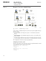
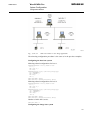
A051600
Fig. 2.3.-1
Network control system
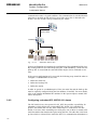
The connected devices - printers, workplaces and process units - can be shared by
several base systems in the network. The workplaces connected to a LAN, for
example, can be used by all base systems connected to the same LAN. Likewise, the
stations and printers connected to NETs can be used by all base systems connected
to the same network of interconnected NETs.
In the network of Fig. 2.3.-1, for example, all the applications in base systems 1 and
3 can use the workplaces on the LAN. The Operator Workstations can be connected
to several base systems and applications simultaneously. The application 5 can use
both printers 1 and 2. A redirection of printout can be done during operation.
2.4.
System self supervision
The System self supervision (SSS) is used in MicroSCADA Pro systems for
supervising and monitoring the system. It provides the status information of
hardware and software by using the symbols of SYS 600 Monitor Pro. System self
supervision consists of:
17
MicroSCADA Pro
System Configuration
SYS 600 9.2
1MRS756112
Configuration Manual
*
*
Supervision application objects
Supervision monitoring
Supervision application objects contain the source for supervision information to be
displayed by supervision monitoring in a supervision display.
2.5.
Event handling
An event is an indication that something has happened in the system. Typical events
are changes of object values, alarms or warnings, or alarm definitions. Events can
cause printouts, automatic control operations, event lists and report database
registrations.
The event list displays events that have occurred in the system. It also informs about
activities by other users, operations of objects, acknowledging alarms, editing of
limit values and so on. With LIB 500 you can define own filters with the event list
tool, depending on what kind of information you want in the event list. One or
several criteria may be used to filter out unwanted information from the event list.
2.6.
Alarm handling
Alarms are generated when something special has occurred in the process. Alarms
can cause audio-visual alarms, changes in the station picture, alarm pictures, alarm
printouts and alarm lists. Information about alarming objects is stored in the alarm
buffer. The information remains in the buffer until the reason for the alarm
disappears or until the alarm is acknowledged.
The alarm list shows all the alarms that appear in the system alarm buffer. The alarm
list is divided into two different lists: one with persisting (active) alarms and one
with fleeting (inactive) alarms. An alarm is usually presented with a text that
explains the reason of the alarm.
Alarms and events can be generated in three different ways:
*
*
*
Process events can generate alarms. The state of the process is evaluated in the
base system, according to the limits that have been set. For example, if a
measured value exceeds the predefined limits, an alarm will occur.
The system itself can generate internal alarms from diagnostic programs, which
supervise the MicroSCADA Pro system components. An alarm will occur, if
there are system communication errors, e.g. if a printer error occurs.
System alarms are generated by an external module. This module can be
considered as a system watch dog. System alarms of this type cannot be included
in the alarm list.
Other devices in the MicroSCADA Pro system can also generate alarms.
18
1MRS756112
MicroSCADA Pro
SYS 600 9.2
System Configuration
Configuration Manual
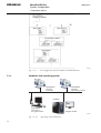
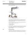
2.7.
Communication gateway
Information needs to be transmitted between the SYS 600 system server and process
units. In some cases information from the process units needs to be transmitted to
the network control centers as well. Commands sent from the network control
centers to process units need to be transmitted in the same way. The data
transmission is a task for the communication system. The process unit protocol is
often different from the network control center protocol. This is why a protocol
conversion is needed.
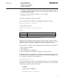
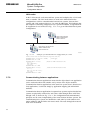
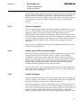
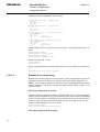
A060437
Fig. 2.7.-1
Communication in the electricity distribution
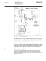
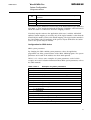
The communication system also handles the communication between other devices
in the MicroSCADA Pro system, for example, between two system servers or two
communication servers. The communication can be divided into upper level
communication and process communication, as shown in Fig. 2.7.-2. Some
protocols used for communication are shown in the picture.
19
SYS 600 9.2
MicroSCADA Pro
System Configuration
1MRS756112
Configuration Manual
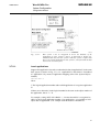
A060438
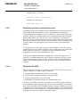
Fig. 2.7.-2
Communication between a NCC (Network Control Center), a COM 500i
(Communication Gateway) and process units can be divided into upper
level communication and process communication.
Upper level communication means communication between the process units, the
COM 500i and the network control center. There can be a SYS 600 system server or
a third-party system in the network control center. The upper level communication is
usually LAN communication that uses TCP connection or an asynchronous serial
communication that uses leased telephone lines, dialed telephone lines, radio links
or power line carriers as the physical media.
Process communication is the communication between the COM 500i and the
protection and control devices connected to the physical process.
Because of electromagnetic disturbances caused by the primary electric process,
optic fibres are mostly used as communication media in the process communication.
The communication line is usually faster than the one used in the upper level
communication due to the larger quantity of data.
2.8.
Peripheral equipment
Peripheral equipments include:
20
1MRS756112
MicroSCADA Pro
SYS 600 9.2
System Configuration
Configuration Manual
*
*
*
2.8.1.
Printers that are connected to base system computers, to a LAN via printer
servers, or to a process communication system.
Alarm I/O adapter
Radio clocks for external clock synchronization (DCF77, GPS)
Printers
A base system can have up to 20 printers connected , either directly or through
LAN. The printers can be of different types, for example, transparent printers,
matrix printers and laser printers. In addition to these printers, the ones defined in
the operating system can be accessed by MicroSCADA Pro.
Each printer has a unique printer number, which can be associated with a certain
task. For example, the task can be an alarm and event printout, hard copy, historical
reports and so on. A printer can be programmed to take over the tasks of another
printer automatically.
Printouts can be produced automatically or manually. The layout of a printout can
be customized. The main printout types are logs, reports, hard copies and
documents. Logs are automatic printouts based on process events. The logs can be
directed to one or more printers.
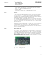
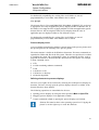
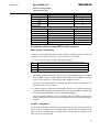
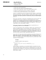
2.8.2.
Alarm output I/O
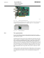
You can define 7 different alarm classes on every process object. The alarm class is
of significance when connecting the alarms to audio or audiovisual alarm signals
through additional circuit boards. MicroSCADA will support three I/O cards for this
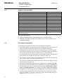
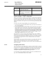
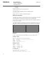
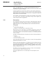
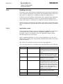
purpose. Supported I/O control cards are ADlink Technoloy Inc's NuDAQ PCI7250, NuDAQ PCI-7256 shown in Fig. 2.8.2.-1, which will support 3.3V PCI bus
and Advantech PC-LabCard series PCI-1760.
A070482
Fig. 2.8.2.-1
NuDAQ PCI-7256
21
SYS 600 9.2
MicroSCADA Pro
System Configuration
1MRS756112
Configuration Manual
2.9.
Time handling
There are two different time sources available for accurate time synchronization,
GPS and DCF77. SNTP method is used to provide resource to IP network clients.
DCF77 radio receivers that are connected directly to PC receive radio timing signals
and synchronize Windows platform or MicroSCADA Pro directly.
The most precise time handling method of MicroSCADA Pro system is to use IEC
61850 OPC Server, which can act as an SNTP client and server. For more details,
refer to IEC 61850 Configuration Manual.
If IEC 61850 OPC Server is not used, it is possible to use a client program and GPS
clock, which synchronize the PC clock. There are many server/client utilities which
can be used. Tardis2000 and Yats32 Synchronization applications and Trimble Ace
III clocks have been used in customer projects.
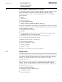
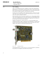
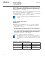
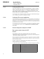
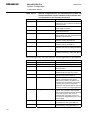
Meinberg’s board PCI511, as shown in Fig. 2.9.-1, has been designed for the
reception of the DCF77 signal, to transfer the time information to a computer with
PCI (PCI-X) bus interface and the translation of the received codes into a serial
telegram. This solution can synchronize MicroSCADA time.
A070483
Fig. 2.9.-1
Meinberg's PCI511
The board GPS170PCI, as shown in Fig. 2.9.-2, has been designed to synchronize
the system time of computers with PCI/PCI-X bus interface.
22
1MRS756112
MicroSCADA Pro
SYS 600 9.2
System Configuration
Configuration Manual
A070484
Fig. 2.9.-2
Meinberg’s GPS170PCI Clocks
The synchronization of the Base System Computer connected to the Com Port of the
Computer using Meinberg GPS 167, as shown in Fig. 2.9.-3, is also possible.
A070485
Fig. 2.9.-3
2.9.1.
Meinberg GPS 167
Time synchronization
For exact and reliable operation, the whole chain between the process and the
MicroSCADA Pro databases must be synchronized: the stations, the communication
units and the base systems.
The MicroSCADA Pro base system works according to the operating system clock,
which is regularly set according to the physical clock of the base system computer.
If an external time synchronization source such as a radio clock or a GPS clock is
used, it sets the physical clock and the operating system clock regularly. The
operator can also set the system time, whereby both the operating system clock and
the physical clock are set simultaneously. However, if the computer uses an external
time synchronization source, the manual time setting has a temporary effect only, as
the time is set regularly by the external time synchronization source. An external
time synchronization source of type radio clock can also be connected to a NET
unit.
The base system time can be read and written on millisecond level, with an accuracy
of 10 milliseconds, with the SCIL functions SYS_TIME and SET_SYS_TIME. For
more information on the functions, refer to the Programming Language SCIL
manual.
23
SYS 600 9.2
MicroSCADA Pro
System Configuration
1MRS756112
Configuration Manual
The time of the communication units can be read and written with the NETn:STM
attribute.
The time of the stations (S.P.I.D.E.R. RTUs and ANSI stations) are synchronized by
means of the Clock Synchronization (SY) attribute. SPACOM units are
synchronized automatically.
2.10.
Mapping devices
Monitors, printers and stations can be mapped for an application, which means that
the application recognizes the devices under logical numbers. The station mapping,
for instance, specifies the station numbers under which the application recognizes
the stations. The station mapping has the following format:
APLn:BSTi = j
i
The logical station numbers as known to the application and the
values.
j
The STA object numbers of the stations.
The printers and stations have a default mapping, which means that each logical
application recognizes them under the real object numbers. Therefore, the printer
and station mapping is needed only if the application for some reason needs to know
the devices under logical numbers. If there are no obstacles, let the logical numbers
be the same as the object numbers (that is i = j), that is do not change the default
values of printer and station mapping.
The monitor mapping is described in 3.2. Configuring workplaces.
2.11.
Redundancy
A single system is a MicroSCADA Pro system that contains only one unit of each
system component, while a redundant system can contain two base systems, and/or
two NET units and/or two LAN/serial connections dedicated for the same purpose.
The idea with a redundant system is to make the system more safe when doubling
some of its components. In most systems, the component availability is very
important. This means that if one of the system components fails, the other one takes
over the specific functions immediately after it has recognized a breakdown in the
other base system.
In general, the redundancy in process communication and the upper level
communication will follow corresponding standards if specified for the used
protocol. For more details, refer to Section 3.8.3. Configuring redundant IEC
60870-5-104 slaves, Section 3.8.5. Configuring redundant IEC 60870-5-101 slaves
and Section 3.8.4. Configuring redundant RP 570 slaves.
24
1MRS756112
MicroSCADA Pro
SYS 600 9.2
System Configuration
Configuration Manual
2.12.
Mirroring
Process database mirroring provides a powerful means for sharing process data in a
MicroSCADA Pro network with minimal engineering effort. Mirroring can be
considered as one implementation of the client/server model of computing. The
server application "host" delivers process data to one or more client applications
"images". Usually, the host and the images are located in different computers. Local
mirroring, that is mirroring between two applications within a MicroSCADA Pro
computer, is also supported.
In a hierarchical MicroSCADA Pro network, an image can act further as a host to
one or more upper-level images. This is called hierarchical mirroring.
Mirroring can be used in several ways in different network configurations. Some
examples are described in 3.9. Configuring mirroring.
The most common use of mirroring is to build a hierarchical control system, where
several substations are connected to a network control center, each location running
a MicroSCADA Pro system. By using hierarchical mirroring, a wider network
containing substations, regional control centers and a main control center can be
built. This use is quite close to what COM 500i is used for. However, because of a
common system architecture and a proprietary communication protocol, the
communication is much more efficient and the required engineering work to build
up the system is minimal. In addition, several special functions, such as event
buffering during communication breaks and handling of hot-stand-by
configurations, are automatically taken care of, without any application-level SCIL
programming.
Within a substation, one SYS 600 MicroSCADA Pro system can replace the pair of
SYS 600 and COM 500i systems which were previously often required to control
and supervise the substation. Even if COM 500i is needed to communicate with a
non-MicroSCADA Pro network control center, the sharing of process data between
the COM 500i and SYS 600 can be done by mirroring. In this case, SYS 600 and
COM 500i can run as separate applications in one computer.
Mirroring can even be used to share process data among totally different kinds of
applications. For example, electrical SCADA and district heating SCADA can share
some indications, measurements and events. In this case, both applications can act in
double roles, both as a host and as an image.
2.13.
OPC connectivity
SYS 600 system provides OPC connectivity towards the process and upper level
communication. Process units containing generic OPC server implementation can
be connected into SYS 600 system by using the External OPC DA Client or OPC
Alarms & Events Client. Additionally SYS 600 system may expose its applications
towards upper level systems via OPC Data Access Server, OPC Alarms & Events
Server or SYS 600 Application OPC Server.
25
MicroSCADA Pro
System Configuration
SYS 600 9.2
1MRS756112
Configuration Manual
A070736
Fig. 2.13.-1
2.14.
OPC connectivity
Capacity and performance scalability
The SYS 600 system is highly scalable with regards to capacity and performance.
This allows systems of significant differences in size to be built, starting from small
monitoring systems with tens of IO's to large systems with hundreds of thousands of
IOs.
The capacity and performance of the system is mainly affected by the computer
processing capacity, which can be adjusted in two ways:
*
*
by using computer(s) with various processing capacity
by using various numbers of computers
Computer capacity
The computer type can be selected in order to match the capacity requirements of
the system. The most important parameters are:
*
*
*
CPU performance
RAM capacity
Disk capacity
The most important system characteristics that must be considered when designing
the system are:
*
*
26
process communication load
number of simultaneous workplaces
1MRS756112
MicroSCADA Pro
SYS 600 9.2
System Configuration
Configuration Manual
*
*
intensity of archiving, calculations and reporting
possible other system specific functions
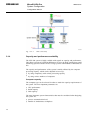
Distributing processing capacity
In this context one system is characterized by one common image of the process.
This means in SYS 600 terms one common process database and one common event
archive which allows all alarms and events to be managed in one alarm/event list. If
this one common process image is not required the system can be built up of several
independent sub-systems, example: with common workplace computers but with
individual windows (Monitor Pro) for the different sub-systems.
So in the system there is always one server that hosts the complete process database.
This server can of course be redundant (HSB) as described in a separate chapter. The
process database is however very efficient and can handle tens of thousands of
updates per second. Functions that can be distributed are process communication
(PC-NET, IEC 61850 OPC Server & Client), Archiving, Reporting, Workplace
processing and other post-processing activities. The distribution of the different
functions is done so that each computer is allocated to its own task and the process
data is mirrored between the computers by means of the Mirroring function in
SYS 600.
Operator Workstations
Workstation
Server
External system
Archiving
and
Reporting
External system
interface (ODBC,
OPC, etc.)
Mirroring
System Server
(Common Process Image)
Mirroring
Communication
Front-ends
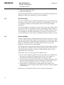
Fig. 2.14.-1
System architecture
The picture above is an example of a system where different functions have been
distributed to achieve a higher capacity. The process image of the System Server can
be mirrored up to ten different servers. The number of communication front-end
27
SYS 600 9.2
MicroSCADA Pro
System Configuration
1MRS756112
Configuration Manual
connected to the system server is mainly limited by practical factors and the system
server capacity. All nodes connected to the system by means of the mirroring
functionality have SYS 600 installed.
Operator Workstations
System Server
ACP
OPC DA Client
IEC 61850
OPC Server
Fig. 2.14.-2
System architecture
The communication front-end can also be distributed in other ways depending on
the communication protocols used. In a IEC 61850 system the OPC DA Client and
the IEC 61850 OPC server can run in it own computer. Also protocols or protocol
converters implemented with CPI (Communication Programming Interface) can run
in its own computer. In this configuration SYS 600 is not needed in the front-end
computer. For more information on how to build the IEC 61850 system, refer to
'IEC 61850 System Design manual'.
28
1MRS756112
MicroSCADA Pro
SYS 600 9.2
System Configuration
Configuration Manual
3.
Configuration
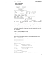
The MicroSCADA Pro configuration software is composed of objects and data in
the base systems and communication units (NETs), as shown in Fig. 3.1.-1:
*
*
Each base system contains a set of base system objects that specify the base
system itself and its environment. During the operation, the base system objects
are in the primary memory of the base system computer. The base system objects
are created with SCIL commands when the MicroSCADA Pro base system is
started. They can be added and modified during the operation.
Each communication unit contains a set of system objects that specify the unit
itself and its environment. During the operation, the system objects are in the
memory of the PC (PC-NETs). The NET programs contain a preconfiguration,
which gives the system objects default values. The system objects can be added
and modified during the system operation.
The process units (stations) contain their own configuration definitions that must be
regarded in the MicroSCADA Pro configuration. For some station types, the
configuration can be built in MicroSCADA Pro and downloaded to the stations.
Data files
The data files can be changed with a text editor (DOS format). They cannot be
changed while the workplace is in operation, because a modification requires that
the actual workplace (including the communication units) is restarted.
3.1.
Configuring system server
As a rule, when a device is added to the MicroSCADA Pro system, several
configuration modules are affected. For example, when a process unit (station) is
connected to a NET, additions and modifications are required in:
*
*
Base system which uses it: base system objects.
Communication unit to which it is directly connected: system objects.
Concerning PC-NET and LONWORKS network, the configuration work is done
with the System Configuration Tool. It automatically gives default values which can
be changed, if needed.
The MicroSCADA Pro system configuration can be changed any time. However, in
some cases a shutdown and restart is required for activating the changes.
29
SYS 600 9.2
MicroSCADA Pro
System Configuration
1MRS756112
Configuration Manual
A051598
Fig. 3.1.-1
3.1.1.
The configuration software modules in MicroSCADA Pro
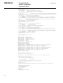
Hardware and operating system
Workstation
eXceed
X-monitor
Workstation
eXceed
VS-remote monitor
SYS600
Workstation
Thin Client
Pro type monitor
VS type monitor
A070491
Fig. 3.1.1.-1
30
Operating system architecture
1MRS756112
MicroSCADA Pro
SYS 600 9.2
System Configuration
Configuration Manual
MicroSCADA Pro supports Intel x86 compatible processors and Microsoft’s x32
(32-bit) compatible operating systems: Windows XP, Windows 2000 Server and
Windows Server 2003. For information on requirements, refer to Installation and
Administration Manual.
MicroSCADA Pro can be installed as part of Windows domain, but it cannot be
installed to the domain server. A Windows Domain is a logical grouping of
computers that share common security and user account information. This
information is stored in a master directory database (SAM) which resides on a
Windows server designated as a domain controller.
We recommend to use MicroSCADA in a stand-alone server to avoid complicated
errors.
It is possible to run 32-bit programs on Intel x64 architecture
processors.
3.1.2.
Systems (SYS)
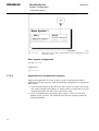
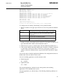
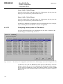
Create a SYS:B object with at least the following attributes (see the example in
Fig. 3.1.3.-1):
Table 3.1.2.-1
Mandatory attributes
ND
The node number of the base system. The node number must be
unique within the entire MicroSCADA Pro network, see .
SA
The MicroPROTOCOL station address of the base system. Like the
node number, the station address must be unique within the
network, see .
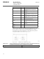
The following attributes are optional:
Table 3.1.2.-2
Optional attributes
ER
The use of the base system as a routing node. It means that if
routing is enabled in a specific base system, it can route messages
addressed to other nodes. Refer to the System Objects manual.
DN, DS
The default node number and default station type. These attributes
should not be used.
SH
Shadowing attribute. This attribute is used for the configuration of
hot stand-by, see 3.8. Configuring redundancy.
TI
Timeout length for node communication. The attribute can be locally
and temporarily sidestepped by a SCIL function (TIMEOUT).
PC, RC
Memory cache space attributes, see ‘Tuning memory parameters’ in
this section.
FS
File Sync. The flushing of buffered data on to a disk.
DE
Allowing applications in the base system to be accessed by other
software using DDE.
AA
The use of standard audio-visual alarm unit.
CA, CF, CL, TZ
Attributes related to an external clock. Refer to the System Objects
manual.
31
SYS 600 9.2
MicroSCADA Pro
System Configuration
1MRS756112
Configuration Manual
SD, SP
SPACOM devices connected directly to the base system.
DM, TF
Debug mode and time format.
The following attribute is read-only and is therefore not set:
Table 3.1.2.-3
DU
Read-only attribute
The attribute states whether the DDE server is usable or not. Its
value is 0, if the DDE server has not been started. If the DDE server
has been started, its value is 1 if a user has logged on to the base
system computer, otherwise 0.
The SYS:B object definition must come first in the base system
configuration file SYS_BASCON.COM, otherwise the system does
not start.
3.1.2.1.
System configuration
The system configuration of the MicroSCADA Pro base system is defined in the
SYS_BASCON.COM configuration file.
The file is a text file containing SCIL statements for creating the base system (B)
objects. The System Base Software package contains two SYS_BASCON.COM
template files, one for configuring a single base system and one for configuring a
hot-stand-by base system. During installation, the template file for a single base
system, SYS_BASCON$COM, is copied to SYS_BASCON.COM if the
SYS_BASCON.COM does not previously exist. The template file for hot-stand-by
systems is called SYS_BASCON.HSB.
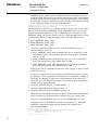
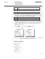
The SYS_BASCON$COM template file defines a system configuration as
presented in Fig. 3.1.2.1.-1. The configuration consists of an application called
“TUTOR”. Two PRI objects, one “normal” and one “transparent”, are connected to
the Windows printer manager. Both objects correspond to one physical printer. A
third PRI object is connected to a NET node. The fourth PRI object, PRI15, is
defined as a log printer printing to a specified log file.
The base system has two communication links to NET nodes. One node is
connected to the TCP/IP LAN link. The other node, which is running the PC-NET
communication software, is connected over an integrated link to the base system.
The configuration allows ten MicroSCADA Pro monitors to be opened to the
TUTOR application.
32
1MRS756112
MicroSCADA Pro
SYS 600 9.2
System Configuration
Configuration Manual
A051601
Fig. 3.1.2.1.-1
The system configuration defined by the delivered configuration
software
Also the configuration files NET_BASCON.COM and PC_NET.COM, included in
the delivery conform with the configuration in Fig. 3.1.2.1.-1.
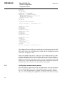
The contents of the SYS_BASCON$COM file is listed below. Some configuration
definitions have been excluded by commenting them. They can be taken into use by
removing the comment sign in front of the #CREATE command that creates the
base system object.
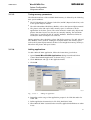
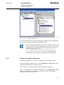
To edit the current SYS_BASCON.COM:
1. Open the MicroSCADA Pro Control Panel.
2. Click Admin.
3. Click Config.
The SYS_BASCON.COM file is opened in the Notepad program for editing.
;File:
Sys_bascon.com
;Desription: Standard Base system configuration file
;
Version 9.0
;——————————————————————————
;——————————————————————————
;Base System Object
@l_Standard_Paths = do(read_text("/STool/Def/Path_Def.txt"))
#CREATE SYS:B = List(SA = 209,;Station address of base system
ND = 9,;Node number of base system
TM = "SYS",;Time Master, SYS or APL
TR = "LOCAL",;Time Reference, LOCAL or UTC
DN = 1,;Default NET node number
DS = "STA",;Default STA type: E.G. STA,RTU,SPA,REX
DE = 0,;DDE server 0=disabled, 1=enabled
OP = 1,;OPC server 0=disabled, 1=enabled
PC = 6000,;Picture Cache (kB)
RC = 1000,;Report Cache (kB)
- ;MS-STOOL Settings
PH = %l_Standard_Paths,SV = (0,;System Variables
list(t_System_Configuration_File = "sys_/SysConf.ini",- ;System
Configuration information
33
SYS 600 9.2
MicroSCADA Pro
System Configuration
1MRS756112
Configuration Manual
b_Conf_Mech_In_Use = TRUE,- ;enables/disables start-up configuration
b_SSS_Mech_In_Use = TRUE,- ;enables/disables system self supervision
routing
t_Version = "8.4.3")),- ;Operating System events
OE = 0,;1=Enabled, 0=Disabled
OT = (Bit_Mask(0,1,2,3,4),- ;Application events (Bit 0=ERROR, 1=WARNING,
2=INFORMATION, 3=AUDIT_SUCCESS, 4=AUDIT_FAILURE)
Bit_Mask(0,1,2,3,4),- ;System events (Bit 0=ERROR, 1=WARNING, 2=INFORMATION,
3=AUDIT_SUCCESS, 4=AUDIT_FAILURE)
Bit_Mask(0,1,2,3,4)),- ;Security events (Bit 0=ERROR, 1=WARNING,
2=INFORMATION, 3=AUDIT_SUCCESS, 4=AUDIT_FAILURE)
FS = "NEVER")
;File sync. criteria: NEVER,MAINT,SET,CHECKPOINT,ALWAYS
;——————————————————————————
;Communication Links
;NOTE! Use the System Configuration Tool to create a link for the PC-NET!
#CREATE LIN:V = LIST(;Link to DCP-NET (requires DCP driver)
LT = "RAM",;Link type
SD = "RM00",;DCP card (first:RM00, second RM01)
RE = "BCC",;Redundancy
TI = 2,;Timeout length (s)
NA = 3,;NAK limit
EN = 3)
;ENQ limit
;#CREATE LIN1:B = %LIN
#CREATE LIN:V = LIST(LT = "LAN")
;Link type
;#CREATE LIN2:B = %LIN
;Link to other SYS or LAN frontend (requires TCP/IP)
;——————————————————————————
;Node objects (NET’s and SYS’s)
;NOTE! Use the System Configuration Tool to create nodes for the PC-NET!
#CREATE NOD:V = LIST(;Node for DCP-NET
LI = 1,;Link number
SA = 201)
;Station address: 0..255
;#CREATE NOD1:B = %NOD
#CREATE NOD:V = LIST(LI = 2,SA = 202)
;#CREATE NOD2:B = %NOD
;Node for LAN frontend or SYS
;——————————————————————————
;Printers
;#do Read_Text("sys_/pr_default.dat") ;This line is needed for the transparent
printer below
;#CREATE PRI:V = LIST(;Transparent type printer
; TT = "LOCAL",;Translation type
; DT = "TRANSPARENT",- ;Device type
; OJ = 1,;Printer opened on job basis
; DC = "LINE",;Device connection: CONSOLE, LINE OR NET
; CS = %CS,;Control sequences
; SD = "\\My_NT\My_Printer",- ;System device name
; LP = 66)
;Lines per page
;#CREATE PRI1:B = %PRI
#CREATE PRI:V = LIST(TT = "LOCAL",DT = "NORMAL",DC = "LINE",SD = "\\My_NT\My_Printer",LP = 66)
;#CREATE PRI2:B = %PRI
#CREATE PRI:V = LIST(TT = "LOCAL",DT = "COLOR",DC = "NET",ND = 4,;NET node number: 1..99
TN = 1,;Translated object number (printer nr in net)
LP = 66)
;#CREATE PRI3:B = %PRI
;#CREATE PRI:V = LIST((History logging Policy)
34
;Required if HP of application is "EVENT_LOG"
1MRS756112
MicroSCADA Pro
SYS 600 9.2
System Configuration
Configuration Manual
; TT = "LOCAL",; OD = "LOG",;Output destination (LOG, PRINTER)
; LL = "DAY",;Log Length (DAY, WEEK, MONTH)
; LD = "/APL/TUTOR/PICT",- ;Log directory
; LP = 0)
;#CREATE PRI15:B = %PRI
;——————————————————————————
;Monitors
#LOOP_WITH I = 1..5
#Create MON’I’:B = LIST(TT = "LOCAL",;Translation type
DT = "VS")
;Visual SCIL monitor
@MON_MAP(%I) = -1
#LOOP_END
#LOOP_WITH I = 6..10
#CREATE MON’I’:B = LIST(TT = "LOCAL",;Translation type
DT = "X")
;X monitor
@MON_MAP(%I) = -1
#LOOP_END
;——————————————————————————
;Applications
;The usage of OI OX -attributes (required by LIB 500)
@SV(15) = LIST(Process_Objects=LIST(OI=LIST(Title1=VECTOR("Substation"),Title2=VECTOR("Bay"),Title3=VECTOR("Device"),Title4=VECTOR(""),Title5=VECTOR(""),Length1=10,Length2=15,Length3=5,Length4=0,Length5=0,Field1=VECTOR("STA"),Field2=VECTOR("BAY"),Field3=VECTOR("DEV"),Field4=VECTOR(""),Field5=VECTOR("")),OX=LIST(Title1=VECTOR("Object text"),Length1=30)))
;Create Application specific global paths
@l_Global_Paths = list()
;Add LIB5xx global paths to list if LIB5xx installed
@t_LIB_Path_Def_File = "/LIB4/Base/Bbone/Use/Bgu_Glpath.txt"
#if File_Manager("EXISTS", Fm_Scil_File(%t_LIB_Path_Def_File)) #then #block
#error continue
@v_File_Contents = read_text(%t_LIB_Path_Def_File)
#if substr(%v_File_Contents(1),5,16) == "LIB 500 revision" and substr(%
v_File_Contents(1),22,5) >= "4.0.2" #then #block
#modify l_Global_Paths:v = do(read_text(%t_LIB_Path_Def_File))
#block_end
#error stop
#block_end
#if substr(SYS:BPR, 1, 7) == "SYS_600" #then #block ; PP
;Add SA_LIB global paths to list
@t_SALIB_Path_Def_File = "/SA_LIB/Base/Bbone/Use/Bgu_Glpath.txt"
#if File_Manager("EXISTS", Fm_Scil_File(%t_SALIB_Path_Def_File)) #then #block
#error continue
@v_File_Contents = read_text(%t_SALIB_Path_Def_File)
#if substr(%v_File_Contents(1),5,14) == "SA LIB version" and substr(%
v_File_Contents(1),20,5) >= "1.0.0" #then #block
#modify l_Global_Paths:v = do(read_text(%t_sALIB_Path_Def_File))
#block_end
#error stop
#block_end
#block_end
35
SYS 600 9.2
MicroSCADA Pro
System Configuration
1MRS756112
Configuration Manual
#CREATE APL:V = LIST(TT = "LOCAL",;Translation Type
NA = "TUTOR",;Name of application directory
AS = "HOT",;Application state (COLD,WARM,HOT)
PH = %l_Global_Paths,-; PQ = 15,;Number of parallel queues/ Needed in COM500 Applications
-; QD = (1,1,0,0,0,0,1,1,1,1,1,1,1,1,1),- ;Parallel queue dedication/ Needed in
COM500 Applications
SV = %SV,;System variable (RESERVED)
CP = "SHARED",- ;Color Allocation Policy
-; RC = VECTOR("FILE_FUNCTIONS_CREATE_DIRECTORIES"),- ;Revision compatibility
HP = "DATABASE",- ;History Logging Policy ("DATABASE", "EVENT_LOG", "NONE")
EE = 1,;System Events Operating System Events (1=Enabled, 0=Disabled)
AA = 1,;Number of APL-APL servers
MO = %MON_MAP,- ;Monitor mapping
PR = (1,2,3))
;Printer mapping
#CREATE APL1:B = %APL
;#CREATE APL:V = LIST(- ;LIB5xx Demo Application
; TT = "LOCAL",;Translation Type
; NA = "510_403_1",- ;Name of application directory
; AS = "HOT",;Application state (COLD,WARM,HOT)
; PH = %l_Global_Paths,; SV = %SV,;System variable (RESERVED)
; CP = "SHARED",- ;Color Allocation Policy
; RC = VECTOR("FILE_FUNCTIONS_CREATE_DIRECTORIES"),- ;Revision compatibility
; HP = "DATABASE",- ;History Logging Policy ("DATABASE", "EVENT_LOG", "NONE")
; EE = 0,;System Events Operating System Events (1=Enabled, 0=Disabled)
; MO = %MON_MAP,- ;Monitor mapping
; PR = (1,2,3))
;Printer mapping
;#CREATE APL1:B = %APL
;——————————————————————————
;Station Types
#SET STY3:BCX = "ANSI X3-28"
#SET STY4:BCX = "SPIDER RTUs"
#SET STY5:BCX = "SINDAC (ADLP80 S)"
#SET STY6:BCX = "P214"
#SET STY7:BCX = "SINDAC (ADLP180)"
#SET STY8:BCX = "PAC-5"
#SET STY9:BCX = "SATTCON/COMLI"
#SET STY17:BCX = "LON"
#SET STY20:BCX = "LCU 500"
#SET STY21:BCX = "SPACOM"
#CREATE STY22:B = LIST(NA = "SPI", DB
#CREATE STY23:B = LIST(NA = "LMK", DB
#CREATE STY24:B = LIST(NA = "ADE", DB
#CREATE STY25:B = LIST(NA = "PCO", DB
#CREATE STY26:B = LIST(NA = "WES", DB
#CREATE STY27:B = LIST(NA = "ATR", DB
#CREATE STY28:B = LIST(NA = "PLC", DB
#SET STY29:BCX = "IEC"
#SET STY30:BCX = "DNP"
=
=
=
=
=
=
=
"STA",
"REX",
"STA",
"STA",
"STA",
"STA",
"RTU",
CX
CX
CX
CX
CX
CX
CX
=
=
=
=
=
=
=
"S.P.I.D.E.R/RP570")
"LonMark")
"Ademco")
"Procontic / RCOM")
"Westinghouse")
"Alpha Meter")
"PLC")
;——————————————————————————
;Node, Link for PC-NET Stations
@i_Status = do (read_text("Sys_Tool/Create_C.scl"), "BASE_SYSTEM")
;——————————————————————————
;LAN node name of the computer
@t_lan_node_name = "Basesystem1"
@i_system_node
= SYS:BND
#set nod’i_system_node’:bnn = %t_lan_node_name
;——————————————————————————
;Other Stations
;NOTE! Use the System Configuration Tool to create stations for the PC-NET!
;NET 1 (DCP-NET) stations
;#CREATE STA:V = LIST(; TT = "EXTERNAL",; ST = "RTU",; ND = 1,; TN = 1)
;#CREATE STA1:B = %STA
36
1MRS756112
MicroSCADA Pro
SYS 600 9.2
System Configuration
Configuration Manual
If the MicroSCADA Pro base system revision 8.4.2 or later is used
together with applications that were created with earlier revisions of the
base system, for example by using LIB 4.0.1, the revision
compatibility switch NO_ALIAS_CHECKING should be turned on.
This is done by adding "NO_ALIAS_CHECKING" to the RC attribute
of the application in SYS_BASCON.COM.
SYS_BASCON.COM:
#CREATE APL:V = LIST(...
RC =
VECTOR("FILE_FUNCTIONS_CREATE_DIRECTORIES" ,"NO_ALIAS_CHECKING") ,...
3.1.2.2.
Memory configuration
The configuration file SYS_CONFIG.PAR is a text file containing settings of
system parameters that cannot be set with SCIL. The file is read at system start-up
before the execution of SYS_BASCON.COM. The configuration file
SYS_CONFIG.PAR can be edited with a text editor.
SYS_CONFIG.PAR can contain the following parameters and set values:
*
MEMORY_POOL_SIZE specifies the size of the global memory pool in
megabytes (MB). Possible values are divisible with four, that is 4, 8, 12, 16, 20,
24, and so on. The default is 64 MB, if no value is given in SYS_CONFIG.PAR.
For example the line: MEMORY_POOL_SIZE = 100 sets the size of the global
memory pool to 100 MB.
*
MEMORY_POOL_ADDRESS specifies the start virtual address of the global
memory pool. The start address (default value 30000000) should be changed to a
new value by trial and error or examining the DrWatson log if the start of a
monitor or an external program (Application Extension Program or Integrated
Program) fails and the message “? Map_Global_Memory (MapViewOfFileEx):
487” is shown in the Notification Window.
The address is given as an 8-digit hexadecimal number with 6 trailing zeroes.
Any value between 20000000 and 6F000000 can be tried. A good value is found
quickly, if sequence 20000000, 28000000, 30000000, and so on is used. When a
valid value is found, it can be used in all MicroSCADA Pro installations running
the same external programs and the same operating system configuration. The
value does not depend on MicroSCADA Pro configuration, such as number of
monitors or network connections.
The parameter MEMORY_POOL_HOLE offers an alternative and
recommended way of finding a valid memory pool address. It is easier to use,
because the MicroSCADA Pro program does the trial-and-error procedure.
37
MicroSCADA Pro
System Configuration
SYS 600 9.2
1MRS756112
Configuration Manual
*
MEMORY_POOL_HOLE advises the MicroSCADA Pro start-up code not to
use the specified virtual memory area for the global memory pool. The parameter
should be written into the parameter file only if a monitor process or an external
program fails to initialize and displays an error message of the following format
in the Notification Window (and SYS_ERROR.LOG):
Add the following line to sys_config.par and restart MicroSCADA Pro
MEMORY_POOL_HOLE = 30000000 - 301FFFFF
The line should be copied to sys_config.par exactly as shown in the error message.
Do not touch the parameter MEMORY_POOL_ADDRESS. After a restart, the
program should start without errors. The configuration file can contain several
MEMORY_POOL_HOLE lines, because there is a slight possibility that even the
second start-up fails now suggesting another hole in the pool address space.
*
*
*
PICO_MEMORY_POOL_SIZE
REPR_MEMORY_POOL_SIZE
PRIN_MEMORY_POOL_SIZE
These three parameters define the sizes of the local memory pools of
MicroSCADA Pro processes:
*
*
*
PICO_MEMORY_POOL_SIZE determines the size (as megabytes) of the
local memory pool of all the monitor processes in the system. The default
value is 16 MB.
REPR_MEMORY_POOL_SIZE determines the size of the local memory
pool of all repr processes. The default value is 8 MB.
PRIN_MEMORY_POOL_SIZE determines the size of the local memory
pool of all prin processes. The default value is 4 MB.
Setting a pool size to 0 demands the processes of the category to always use the
global memory pool.
If a process requires more memory than the specified memory pool size allows,
the dialog box "SCIL Application Error/Memory Pool Exhausted" is displayed.
The dialog box displays a critical error with information about which pool
caused the error. The information is either "Local memory pool exhausted" or
"Global memory pool exhausted".
*
*
*
ANALOG_SWITCH_STATE_CLOSED (default = 1)
ANALOG_SWITCH_STATE_OPEN (default = 2)
ANALOG_SWITCH_STATE_MIDDLE (default = 0)
These parameters define the translation of the CLOSED, OPEN and MIDDLE
states returned by the program interface function SCIL_Get_Switch_State.
If the SYS_CONFIG.PAR file does not exist, the default values are used.
A template, SYS_CONFIG$PAR is copied to \sc\sys\active\sys_ during the
installation of the System Base Software package. The contents of the
SYS_CONFIG$PAR is:
;File:
Sys_config.par
;Description: Configuration for 'static' base system parameters
;
leading ';' indicates commented line
;
Version 9.0
;——————————————————————————
38
1MRS756112
MicroSCADA Pro
SYS 600 9.2
System Configuration
Configuration Manual
;
;MEMORY_POOL_ADDRESS
= 30000000 ;Memory pool start address
;MEMORY_POOL_SIZE
= 64
;Must be 4,8,12,16,20,24,28,... (MB)
;PICO_MEMORY_POOL_SIZE
= 16
;Memory Pool for Monitor processes
;REPR_MEMORY_POOL_SIZE
=8
;Memory Pool for Report processes
;PRIN_MEMORY_POOL_SIZE
=4
;Memory pool for Printer processes
;
;ANALOG_SWITCH_STATE_OPEN
=2
;The semantics for MicroTOPOLOGY of AI
;ANALOG_SWITCH_STATE_CLOSED = 1
;process objects used for indicating the
;ANALOG_SWITCH_STATE_MIDDLE = 0
;state of a switching device
3.1.3.
Applications (APL)
A local application is situated in the base system in question, which means that all
the application software is stored in the computer as a directory branch under the
application directory apl. For example, the application software of the local
application "sample" is stored in the directory \sc\apl\sample.
The application directory branch with its subdirectories must exist
before a local application can be defined in the base system
configuration (refer to the Installation manual).
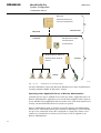
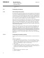
A051602
Fig. 3.1.3.-1
3.1.3.1.
Example of the fundamental definition of a base system and the definition
of two local applications.
Configuring APL objects
Create an APLn:B object ('n' = 1 ... 250) and assign it the following attributes (refer
to the System Objects manual):
39
SYS 600 9.2
MicroSCADA Pro
System Configuration
1MRS756112
Configuration Manual
NA
Application Name. The application name is the name of the
application directory branch containing the application software
(for example "SAMPLE" according to the example above).
MP
Monitor mapping, see the headline "Device Mapping" below.
AS
"HOT" if the application is running.
AP
Application mapping if the application communicates with other
applications within the same or in different base systems (see ).
ST, PR
Printer and station mapping. These attributes are generally not
needed, see the headline "Device Mapping" below.
"LOCAL"
TT
EM, HB, PM
History buffer and queue lengths, see the headline "Tuning
Memory Parameters”.
PQ
Number of parallel queues.
QL
Maximum length of process queries.
See the examples in Fig. 3.1.3.-1.
At least one local application must be created in SYS_BASCON.
COM, given a name (NA), set to "LOCAL" (TT) and to "HOT" (AS)
and mapped for at least one monitor (MO).
The application that is created first in SYS_BASCON.COM is the default
application. If no application number is given when opening a MicroSCADA Pro
monitor, the default application is chosen. Likewise, if no application number given
when using the program interface, the default application is addressed.
3.1.3.2.
Mapping devices
Monitors, printers and stations can be mapped for an application, which means that
the application recognizes the devices under logical numbers. The station mapping,
for instance, specifies the station numbers under which the application recognizes
the stations. The station mapping has the following format:
APLn:BSTi = j
i
The logical station numbers as known to the application and the
values.
j
The STA object numbers of the stations.
The printers and stations have a default mapping, which means that each logical
application recognizes them under the real object numbers. Therefore, the printer
and station mapping is needed only if the application for some reason needs to know
the devices under logical numbers. If there are no obstacles, let the logical numbers
be the same as the object numbers (that is i = j), that is do not change the default
values of printer and station mapping.
The monitor mapping is described in 3.2. Configuring workplaces.
40
1MRS756112
MicroSCADA Pro
SYS 600 9.2
System Configuration
Configuration Manual
3.1.3.3.
Tuning memory parameters
The allocation and use of the available RAM memory is affected by the following
base system attributes:
*
*
*
The SYS:B attributes PC (Picture Cache Size) and RC (Report Cache Size), refer
to the System Objects manual.
The APLn:B attribute HB (History Buffer), refer to the System Objects manual.
The picture cache and report cache memory space is common to all the
applications in the base system. The cache memories contain only objects and
pictures that have been in use, but are not currently running. The maximum
cache space is specified by the PC and RC attributes. When these limits are
reached, the least used objects are removed.
During operation, there should be at least 500 kB free memory. The MF, MS and
MU attributes can be used for reading the occupied and the free memory space
(refer to the System Objects manual). If there is not enough free memory, memory is
taken from the picture and report caches.
3.1.3.4.
Adding applications
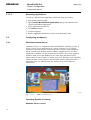
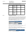
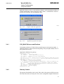
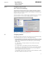
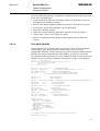
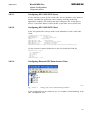
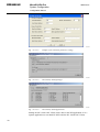
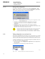
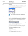
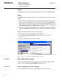
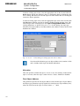
To add a MicroSCADA application, follow the instructions given below:
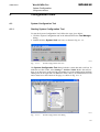
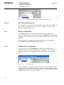
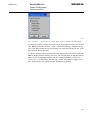
1. Open Control MicroSCADA Applications dialog from MicroSCADA
Control Panel/Admin/Application, as shown in Fig. 3.1.3.4.-1
2. Click Add button and type in the application name.
3. Click OK.
A070734
Fig. 3.1.3.4.-1
Adding an application
4. Depending on the usage of the application, prepare it for LIB 500 and/or for
COM 500.
5. Define application characteristic in file SYS_BASCON.COM.
6. When MicroSCADA is started for the next time, application definitions are taken
in use.
41
SYS 600 9.2
MicroSCADA Pro
System Configuration
1MRS756112
Configuration Manual
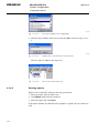
3.1.3.5.
Removing applications
To remove a MicroSCADA application, follow the steps given below:
1. Stop running MicroSCADA.
2. Open Control MicroSCADA Applications dialog from MicroSCADA
Control Panel/Admin/Application.
3. Select application from the list.
4. Click Remove button.
5. Confirm operation.
6. Remove application definitions from the SYS_BASCON.COM.
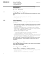
3.2.
Configuring workplaces
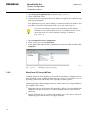
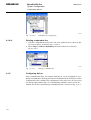
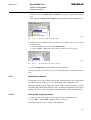
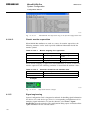
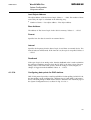
3.2.1.
Windows terminal server
Terminal Services is a component of Microsoft Windows operating systems. It
allows a user to access applications on a remote computer over a network
connection. Terminal Services is Microsoft's take on server centric computing.
Based on the Remote Desktop Protocol (RDP), Terminal Services was first
introduced in Windows NT 4.0 Terminal Server Edition. Next server products,
Windows 2000 Server and Windows Server 2003 have introduced several
improvements and new features. Terminal Services in Windows Server operating
systems provides a new option for MicroSCADA monitor deployment. This is
required to open new MicroSCADA Pro monitors from LAN connected
workstations.
A070554
Fig. 3.2.1.-1
Windows terminal server
Operating System Licensing
Windows Server License
42
1MRS756112
MicroSCADA Pro
SYS 600 9.2
System Configuration
Configuration Manual
The Windows Server 2003 licensing model requires a server license for each copy
of the server software installed. Terminal Services function is included in the
Windows Server license.
Windows Server Client Access License
In addition to a server license, a Windows Server Client Access License (CAL) is
also required. If you want to conduct a Windows session, an incremental Terminal
Server Client Access License (TS CAL) is required as well. A Windows session is
defined as a session during which the server software hosts a graphical user interface
on a device. For Windows sessions, a TS CAL is required for each user or device.
Terminal Server Client Access Licenses
Two types of Terminal Server Client Access Licenses are available: TS Device CAL
and TS User CAL. A TS Device CAL permits one device (used by any user) to
conduct Windows Sessions on any of your servers. A TS User CAL permits one user
(using any device) to conduct Windows Sessions on any of your servers. A single
license server can support multiple terminal servers. There can be one or more
license servers in a domain, or throughout a site.
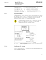
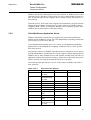
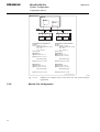
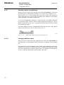
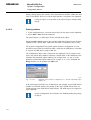
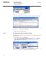
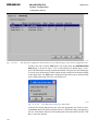
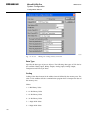
The Terminal Server Licensing Model
Terminal Server Licensing operates between several components, as shown in
Fig. 3.2.1.-2:
43
SYS 600 9.2
MicroSCADA Pro
System Configuration
1MRS756112
Configuration Manual
Microsoft
Certificate Authority &
License Clearinghouse
Infrastructure
Microsoft
Windows Server 2003
Customer
Terminal Server
License Server
Windows Server 2003 and
Windows 2000 Terminal
Product
Servers
Clients
A070474
Fig. 3.2.1.-2
Terminal server licensing model
For more information, refer to the Microsoft Windows Server 2003 Terminal Server
Licensing manual available in Microsoft’s website.
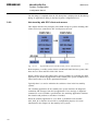
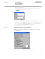
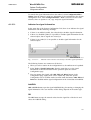
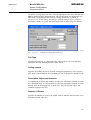
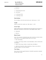
Operating mode: Application Server or Remote Administration
Terminal Services may be enabled in one of the two modes: Application Server or
Remote Administration. Application server mode allows multiple remote clients to
access Windows-based applications that run on the server. This mode must be used
if many concurrent MicroSCADA Pro sessions are opened.
Remote administration mode is designed to provide operators and administrators
remote access. This feature allows you to connect to and manage a server remotely
for up to two connections. Since this is designed as a single-user remote access
solution, no Terminal Server Client Access License (CAL) is required to use
Remote Administration.
44
1MRS756112
MicroSCADA Pro
SYS 600 9.2
System Configuration
Configuration Manual
Windows XP Remote Desktop allows the same function as Windows Server 2003
Terminal Services. But there is always only one active remote desktop session at a
time. If someone logs into the computer from a remote location, the local user is
disconnected.
Terminal Services works with client computers and terminals by using the Remote
Desktop Protocol (RDP). Terminal Services Client software for Windows-based
computers (RDP –clients) is included in Windows Server operating systems. NonWindows-based clients require a third party add-on.
3.2.2.
Citrix MetaFrame Application Server
Windows 2000/2003 Terminal Services supports the native Microsoft Remote
Desktop Protocol (RDP) as well as the Citrix Independent Computing Architecture
(ICA) protocol (via the Citrix add-on).
Citrix MetaFrame/Presentation Server is a remote access/application publishing
product built on the Independent Computing Architecture (ICA), Citrix Systems'
thin client protocol.
This package consists of a handful of products that run on Windows Servers and go
beyond what Windows Terminal Services can do. Support of larger displays than on
Windows Server 2003 Terminal Services and seamless window mode (no frame on
application window) for instance are features, which can be achieved by using Citrix
features and may be useful in the MicroSCADA Pro work place.
The following table provides an overview of the features available with each of
these protocols:
Table 3.2.2.-1
Overview of the features
Feature
Clients
Description
Windows CE-based
thin client
Transport
RDP 5.1
x
ICA
x
Windows XP
Embedded-based
thin client
x
x
ActiveX
x
x
TCP/IP
x
SPX, IPX, NetBEUI
x
x
WAN connection
x
x
Dial-up, VPN, xDSL
x
x
x
x
Direct dial-up (nonRAS)
Audio
System beeps
Stereo Windows
audio
Local printing
Printing to a local
printer attached to a
thin client
x
x
x
45
SYS 600 9.2
MicroSCADA Pro
System Configuration
1MRS756112
Configuration Manual
Table 3.2.2.-1
Overview of the features (Continued)
Feature
Description
Local drive mapping Local drives
accessible from
server-based
applications
46
RDP 5.1
x
ICA
x
Local port
redirection
Redirection of server
ports (LPT/COM) to
local client ports
x
x
Cut and paste
Cut and paste of text
and graphics
between client and
server
x
x
User-centric
Session Access
Client remembers
previous user's
logon name for each
connection
x
Connect to an active
or disconnected
session using a
different screen
resolution.
x
Connect directly to
an application rather
than to an entire
desktop.
x
x
Server-based
applications resize
and minimize similar
to local applications.
x
Application
publishing
Advertise serverbased applications
directly to client
desktops.
x
Resolution
16-bit color depth
x
x
Load balancing
Pooling of servers
behind a single
server address and
for increased
availability.
x
x
Remote control
Viewing and
interacting with other
client sessions (also
called “shadowing”).
x
x
Bitmap caching
Optionally cache
display bitmaps in
memory for
improved
performance.
x
x
Optionally cache
display bitmaps to
disk for improved
performance.
x
x
1MRS756112
MicroSCADA Pro
SYS 600 9.2
System Configuration
Configuration Manual
Table 3.2.2.-1
Feature
Encryption
Description
Multiple-level
encryption for
security of client
communications.
RDP 5.1
x
Multiple-level
encryption on
Windows CE thin
clients.
x
Administrative
means for updating
client connection
software from the
server.
x
x
Pre-configured client Predefined client
with published
applications, IP
addresses, server
names and
connection options.
x
x
Automatic client
update
3.2.2.1.
Overview of the features (Continued)
ICA
x
Verifying client connections
A computer that can be accessed by a user working at a remote location is known as
host. Remote computer is known as the client. The remote desktop connection client
software must be installed in it. Use ping utility to check that TCP/IP connection
between your server and work station is functional. Next, check the Terminal
Services connection by opening desktop for a user on the server. To do this, select
Start > Programs (or All Programs) > Accessories > Communications >
Remote Desktop Connection, as shown in Fig. 3.2.2.1.-1.
A070553
Fig. 3.2.2.1.-1
Opening Remote Desktop Connection
Fill in the computer name or IP address of the host and click Connect. Log on to
Windows dialog box by typing your user name and password.
The Citrix client must be installed on your workstation computer to open ICA
connections. It can be installed from Citrix MetaFrame installation CD or can be
downloaded for free from Citrix website.
A070710
Fig. 3.2.2.1.-2
Opening Program Neighborhood
47
MicroSCADA Pro
System Configuration
SYS 600 9.2
1MRS756112
Configuration Manual
1. Open Program Neighbourhood as shown in Fig. 3.2.2.1.-2.
2. Create connection client.
3. Type name for the connection, add server address, set options for connection and
give logon information.
If no application is given, then a desktop is connected in the ICA window. You
must have created user information on the server you want to log in.
If you are not allowed to open client connection, check whether
terminal services and licensing services are installed on server. Also
check the other server side connection settings, as shown in
Fig. 3.2.2.1.-3.
1. Open Terminal Services Configuration.
2. In the console tree, click Connections.
3. In the details pane, right-click the connection you want to modify, and then click
Properties.
A070711
Fig. 3.2.2.1.-3
3.2.3.
Modifying connection settings
WinnConn XP Server/BeTwin
Common feature for these products is to provide an alternative to Windows Server
2003 operating system as MicroSCADA Pro base system. It is possible to save in
operating system costs and licenses fees especially in small systems.
Following products allow multiple persons to connect and to use a single Windows
XP computer from remote:
*
*
48
WinConnect Server XP software (IPConsult B.V.) allows a server installed with
Windows® XP Pro to host up to 21 remote desktop sessions easily and cost
effectively.
BeTwin (ThinSoft Inc) is a software that enables two to five users to share the
computing power and resources of a single computer.
1MRS756112
MicroSCADA Pro
SYS 600 9.2
System Configuration
Configuration Manual
All these products include their own manuals for installation and application
running. One common feature with Windows Server 2003 installation is, that you
must use register.exe utility to set .dll files available globally to the system and to all
users. This utility is not included either of these two systems. For more information,
refer to MMC500_TS.CMD in Installation Manual.
3.2.4.
Defining MON objects
Base system configuration
Each Classic monitor must be defined as a MON object in the connected base
system. Pro Monitors do not need MON objects. In addition, the MON objects must
be mapped for the applications, which uses them. The monitor objects are defined
equally whether they are opened on the base system monitor or on a workplace.
Fig. 3.2.4.-1 shows an example of a workplace with three MicroSCADA Pro
monitors opened to three applications in two separate base systems.
Make the following object definitions in each base system:
1. Create MONn:B objects, one for each MicroSCADA Pro application monitor
that is opened on the base system monitor or on connected workplaces, see
Chapter 7. Assign the MON objects the following attributes:
DT = “VS” or “X”. Define the monitor as “VS” type, unless it should be able to
show Motif widgets
TT = "LOCAL"
You can create up to 100 MON objects per base system.
2. Define monitor numbers for each application by setting the APLn:BMO attribute
to -1 by using freely chosen monitor numbers as indexes.
Example:
APL1:BMO(1..5) = (-1,-1,-1,-1,-1)
means that monitor numbers 1 ... 5 can be opened to view application 1.
49
SYS 600 9.2
MicroSCADA Pro
System Configuration
1MRS756112
Configuration Manual
Workstation
MON
MON
MON
LAN
Basesystem 1
APL1
APL2
Basesystem 2
APL3
APL4
Configuration of basesystem 1:
Monitors:
#LOOP_WITH I = 1..20
#CREATE MON I :B = LIST(DT = VS ,TT = LOCAL =
#LOOP_END
Configuration of basesystem 2:
Monitors:
#LOOP_WITH I = 1..20
#CREATE MON I :B = LIST(DT = VS ,TT = LOCAL =
#LOOP_END
Application 1:
@MON_MAP(1..20) = -1
#CREATE APL:V = LIST (....
MO=%MON_MAP
....
#CREATE APL1:B = %APL
Application 3:
@MON_MAP(1..20) = -1
#CREATE APL:V = LIST (....
MO=%MON_MAP
....
#CREATE APL3:B = %APL
Application 2:
@MON_MAP(1..20) = -1
#CREATE APL:V = LIST(....
MO=%MON_MAP
....
#CREATE APL2:B = %APL
Application 4:
@MON_MAP(1..20) = -1
#CREATE APL:V = LIST(....
MO=%MON_MAP
....
#CREATE APL4:B = %APL
Config_two_base.eps
A051606
Fig. 3.2.4.-1
3.2.5.
50
Example of a workplace that is connected to two base systems and four
applications
Monitor Pro Configuration
1MRS756112
MicroSCADA Pro
SYS 600 9.2
System Configuration
Configuration Manual
Command Line Support
Usage
FrameWindow.exe
[process|event|alarm(template)|blocking|trends (mode)|reports(mode) display] -ll:x,y -ur:x,y coordsys:world|screen [process display] -display:ulx,uly,width,height -login [username]
[password][application] [process|event|alarm(template)|blocking|trends (mode)|reports
(mode) display] [event|alarm|trends|reports preconf] -loginonce -logoutonce -closeonce
[process|event|alarm(template)|blocking|trends (mode)|reports(mode) display] [event|alarm|
trends|reports preconf] -loginscript [.bat file] -light -wait
[process display]
Opens Process display (path to .v file)
[event display]
Opens an event display (eventlist). Preconfiguration can be given as an additional argument
[|alarm(template)
display]
Opens an alarm display in an appropriate template (alarmlist_temp1|alarmlist_temp2).
Preconfiguration can be given as an additional argument
[blocking display].
Opens blocking display (blockinglist)
[trends(mode) display]
Opens trends display in an appropriate mode (trends_graphical|trends_tabular).
Preconfiguration can be given as an additional argument
[reports(mode) display]
Opens a reports display in an appropriate mode (reports_graphical|reports_tabular).
Preconfiguration can be given as an additional argument
-ll:x,y
Zooms in the lower left coordinates (x,y) of a process display
-ur:x,y
Zooms in the upper right coordinates (x,y) of a process display
-coordsys:world|screen
Defines the coordinate system, if flags -ll and -ur are defined. The world coordinate system is
used by default
-display:ulx,uly,width,
height
Monitor Pro upper left coordinates (ulx, uly), width and height (width, height)
-login
Logs on to the application. Login dialog is displayed, if only the application has been started.
The display can be an additional argument
-loginonce
Logs on to the application that the last Monitor Pro has logged into. Display can be additional
an argument
-logoutonce
Logs out from all Monitor Pro windows with an appropriate user that has the argument defined
-closeonce
Closes all Monitor Pro windows with an appropriate user that has the argument defined
-loginscript
Runs the contents of a BAT file after a successful logon
-lang
Defines the default language used in Monitor Pro when not logged in to any application
-light
Starts Monitor Pro without toolbars and menus
-wait
Waits for MicroSCADA Service to start.
Process Display Specific Configuration Files
Common Process Display Specific Menu Files
Common process display specific menu files are common for all process displays.
Those are seen in process display specific menu before the separator (if some user
has logged in Monitor Pro). Process display specific menu files are after the
separator. For example:
51
MicroSCADA Pro
System Configuration
SYS 600 9.2
1MRS756112
Configuration Manual
Example
FrameWindow.exe
C:\samplepic.v
FrameWindow.exe
C:\samplepic.v -ll:100,400 -ur:300,500
FrameWindow.exe
C:\samplepic.v -display:0,0,400,400
FrameWindow.exe
C:\samplepic.v -light
FrameWindow.exe
alarmlist_temp1
FrameWindow.exe
-loginscript C:\samplefile.bat
FrameWindow.exe
C:\samplepic.v -loginscript C:\samplefile.bat
FrameWindow.exe
eventlist -loginscript C:\samplefile.bat
FrameWindow.exe
-login 510_403_1
FrameWindow.exe
-login demo "" 510_403_1
FrameWindow.exe
-login demo "" 510_403_1 C:\samplepic.v
FrameWindow.exe
-login demo "" 510_403_1 trends_graphical my_trend_preconf
FrameWindow.exe
-login demo "" 510_403_1 alarmlist_temp1 my_alarm_preconf
FrameWindow.
exe -login demo "" 510_403_1 eventlist my_event_preconf
FrameWindow.exe
-loginonce C:\samplepic.v
FrameWindow.exe
-loginonce alarmlist_temp1
FrameWindow.exe
-loginonce -loginscript C:\samplefile.bat
FrameWindow.exe
-loginonce eventlist -loginscript C:\samplefile.bat
Application Specific
Application specific common process display specific menu files are in folder [Appl
path]\PAR\APL\PROCESS\MENU.
User Specific
User specific common process display specific menu files are in folder [User path]
\PROCESS\MENU. If the folder exist the contents of application common process
display specific menu folder is not investigated at all. This makes it possible for
example to skip the application common process display specific menu files if
needed by just defining an empty user specific one.
Visibility Shortcut Files
If visibility files have been defined the following operations are blocked:
*
*
*
File open-menu item won’t let user to open any process graphics pictures
Process graphics picture drag’n’drop to application window is not allowed.
Custom commands concerning opening process graphics displays is blocked.
Application Specific
The shortcut files in [Appl path]\PAR\APL\PROCESS\TOOLBAR_SHORTCUTS
are shown to all users in application process displays toolbar in Monitor Pro. If this
folder is not empty (excluding user specific folders) the files in [Appl path]\PICT\
are left investigated. Other process displays than the ones in application process
displays toolbar are not allowed to open.
52
1MRS756112
MicroSCADA Pro
SYS 600 9.2
System Configuration
Configuration Manual
For backwards compatibility the existing files in old folder are moved
programmatically to new folder when Monitor Pro is started.
User Specific
The shortcut files in [User path]\PROCESS\TOOLBAR_SHORTCUTS\ are shown
to appropriate user only in application process displays toolbar in Monitor Pro. If
this folder is not empty the files in [Appl path]\PICT\ folder and application specific
shortcut files are left investigated. Other process displays than the ones in
application process displays toolbar are not allowed to open.
For backwards compatibility the existing files in old folder are moved
programmatically to new folder when Monitor Pro is started.
Process display menu
A process display menu displays both the common parts for the process pictures and
the specific parts for the currently active process picture.
The menu structure is similar to the Windows Start menu. The menu commands are
organized as folders and files in the file system. Therefore, no special tool is needed
to configure the menu. The configuration is done by organizing the files, such as
programs, documents or shortcuts and the directories in a file system. For example,
a menu command can be:
*
*
*
*
*
*
a file
a folder containing submenu commands
a link
a shortcut to a file
a shortcut to a directory
an Internet hyperlink
Defining shortcuts to process displays
The user access rights can be restricted by showing the needed process displays as
shortcuts. The user can only open the process displays shown in a toolbar, if the
shortcut files have been defined.
The following operations are unavailable for the user:
*
*
*
Opening process displays by using the menu operation Main > Open File.
Dragging process displays to an application window.
Custom commands related to opening the process displays are blocked.
Shortcut files must be there at the operating system level. Copying the
picture is not the right way to create the shortcuts.
53
MicroSCADA Pro
System Configuration
SYS 600 9.2
1MRS756112
Configuration Manual
Application specific process display shortcuts are shown to all users. The shortcut
files are located in Appl path]\PAR\APL\PROCESS\TOOLBAR_SHORTCUTS.
The user is not allowed to open process displays that are not defined on toolbar of
the application specific process displays.
User specific process display shortcuts are shown individually to each user. The user
specific shortcut files are located in [User path]\PROCESS
\TOOLBAR_SHORTCUTS. The user is not allowed to open process displays that
are not defined on toolbar of the user specific process displays.
If the user specific shortcut files exists, the application specific files are
ignored.
Process Display Context Menus
MENUS directory
MENUS directory consists of directories such as all, objecttypes and instances.
*
*
*
*
Menu commands, which are to be shown on each shortcut menu, should be
stored under the directory all.
The directory objecttypes consists of all object types that a station overview can
have. Menu commands that each object type can have are also located here.
It is also possible that an instance of a breaker might have some menu commands
that are instance specific, such as a figure of a breaker, online video stream,
maintenance log or a web link to the manufacturers home page. In that case, the
menu commands are located in \<unique object id>.
The menu for all objects are located in <apl>\MENUS\all.
SYS 600 supports two-letter language codes. When generating the
menu structure, use the /culture <language> option. When the option is
selected, the menu commands are displayed under the culture specific
folder.
Table 3.2.5.-1
Name
54
Menu command descriptions
Description
Path
<apl>
Path of the application
E.g. C:\sc\apl\510_403_1
<object type>
For more information about <apl>\MENUS\objecttypes\
object types, refer to Section <object type>(common menu
for an object type
13.5.7. Object types
<display name>
Name of the display file
(without extension .v)
1MRS756112
MicroSCADA Pro
SYS 600 9.2
System Configuration
Configuration Manual
Menu structures are not shadowed. If a HSB system is used, the menus
have to be manually copied between Hot/Stand-by - computers after
the modifications have been done. Otherwise, the directories are
deleted during the switch-over.
Troubleshooting
Table 3.2.5.-2
Possible problems with context-sensitive shortcut menus
Description of the problem
Possible cause
Only a description of a shortcut menu is There are no
displayed. A message 'No items' or the icon commands in the menu
indicates that the shortcut menu is empty directory, that is, menu
is empty.
Solution
Check that the
application has a menu
structure, see section
13.5 in Application
Design Manual.
Furthermore, check
whether a culture has
been defined similar to
the user for the menu
structure.
The folder is displayed as a menu
command and can be browsed. The folder
does not contain submenu commands
The file type of the
menu command is
unknown. The file has
not been associated
with any program
A menu command is disabled
User is not authorized Check the authorization
level or the link target
to run the menu
command or a link
target does not exist
The custom object type does not have
menu commands
A menu structure was
not generated for the
custom object type or
the type does not have
an SAObjectType
attribute
An instance specific menu structure is not No view was defined
created for a symbol
when the menu
structure was
generated or the
symbol’s Object Name
field is empty
3.3.
Use the Open With
dialog to select the
program in which you
want to open the file
The Open With dialog is displayed when
running a menu command
Add a menu structure
manually for the custom
object type and ensure
that the object has an
SAObjectType attribute
Use Display Builder to
set the Object Name
field for the symbol.
Run the menu
generator and use a
viewpath argument to
generate menus for
instances
Configuring process communication
The configuration of process communication is divided into the following
configuration tasks:
55
MicroSCADA Pro
System Configuration
SYS 600 9.2
1MRS756112
Configuration Manual
*
*
Configuring communication system objects in base system
Configuring process communication units (PC-NET, OPC DA Client, CPI
applications)
In general, the process communication units cannot be created or accessed from any
application before the corresponding system objects in base system has been
configured. The definition method of these system objects depends on used process
communication unit type.
The required base system object types are as following:
*
*
*
*
NODn:B object which in this context defines the node of process
communication unit itself
LINn:B object which defines a communication route from the base system to the
defined node
STAn:B object which defines a station within a defined node
PRIn:B object which defines a printer within a defined node
If the used process communication unit is of type PC-NET and System
Configuration Tool is used, these base system objects are created automatically. If
the System Configuration Tool is not used or the used process communication units
are other than PC-NET, refer to Section 4.1.7.1. Loading online configuration for
more information. System Configuration Tool supports only process communication
units of type PC-NET.
These objects can be also be configured using SYS_BASCON.COM as described in
Section 3.1.2. Systems (SYS) or with SCIL using statement #CREATE.
3.3.1.
Configuring communication system objects in base system
Following system objects are needed for each process communication unit:
Links (LIN)
A link is a data transmission line to another base system, a NET unit or a device.
Each link is defined by a LINn:B object (n = 1 ... 20). A base system can have the
following links:
*
*
One link of type “LAN”. The process communication unit may be directly
connected through LAN link. The LAN link is used between base systems and
the process communication unit may be connected to another base system
(indirect connection). The definition of LAN links is described in Section 3.7.2.
Communicating between applications.
One link of type “INTEGRATED” for each configured PC-NET. This link type
is used only by PC-NET process communication unit and it is created by the
System Configuration Tool. The pc_net process is started when the LIN:B object
of type “INTEGRATED” is created.
Node (NOD)
56
1MRS756112
MicroSCADA Pro
SYS 600 9.2
System Configuration
Configuration Manual
Nodes are directly or indirectly connected base systems and process communication
units. The nodes are defined by NODn:B objects (n = 1 ... 250). A node definition is
needed for:
Communication to the communication units. Each process communication unit
which is recognized by the base system must be defined as a node. These node
definitions are described in Section .
Reading and writing attributes. A node is primarily specified by the used
connection link and the station address of the node. If a node is only indirectly
connected to the base system, the link to the node is the link to the nearest
intermediate node. The link object must have been defined before the node can
be defined.
*
*
Node definition is also used to define another base system in a network. This is
described in Section 3.7.2. Communicating between applications.
Example:
A process communication unit uses LAN link and is configured to be node 3
and its address is 203. The first step in the configuration is create a LIN:B
object of type “LAN” (if not yet created for the base system communication).
The link number is selectable in this situation. The next step is create NOD3:
B object for the process communication unit and assign selected link number
to the NOD3:BLI attribute of the created object. The node address 203 is
assigned to the attribute NOD3:BSA.
This configuration must be present before the process communication unit in
node 3 can be accessed. For more information, on system objects of type
NOD and LIN, refer to System Objects manual. The process communication
unit is PC-NET and System Configuration Tool is used, these base system
objects are created automatically, otherwise the NOD and LIN need to be
created with SCIL. The example above would then require the following
lines:
; L I N 1:B O B J E C T
# C R E A T E L I N : V = L I S T (L T = “L A N ” , T R = “T C P I P ” )
#CREATE LIN1:B=%LIN
;
#
S
#
3.3.2.
N
C
A
C
O
R
=
R
D
E
2
E
3
A
0
A
:B OBJECT
T E N O D : V = L I S T (L I = 1 , 3)
TE NOD3:B=%NOD
Configuring process communication units
The process communication unit types are:
*
*
*
*
*
PC-NET
OPC DA Client
CDC-II Slave
Modbus Slave
Other CPI connected applications
57
SYS 600 9.2
MicroSCADA Pro
System Configuration
1MRS756112
Configuration Manual
Most of the communication protocols are supported by the PC-NET process
communication unit. For more information on attribute PO and a complete list of
protocols, refer to chapter NET lines for communication system in the System
Objects manual. Communication unit of type OPC DA client is used with OPC
connected protocols such as IEC61850. OPC DA client, CDC-II slave, Modbus
slave and other CPI-connected applications. LAN link is used as the communication
route between base system and the communication unit. The following chapters
together with protocol specific manuals will describe the configuration details of
each process communication unit type.
3.3.2.1.
Configuring PC-NET
The recommended way to configure process communication unit of type PC-NET is
to use System Configuration Tool. While creating the full configuration, it provides
a set of possible selections in each step. In practise, these selections are mainly
protocol specific line type and station types. The usage of the System Configuration
Tool is described in Chapter Configuration tools. It is also possible not to use the
System Configuration Tool and create the line and station configuration using SCIL.
The protocol specific manuals contain examples of how this is done with each
protocol. This method is often used when a MicroSCADA system is updated to a
newer release and the amount of changes to the system is tried to minimize.
When the PC-NET program is started, it reads the initial configuration file PC_NET.
CF1, which is a text file located in the SYS- directory. It defines the basic
communication nodes and addresses to enable the communication to an application
that downloads the total configuration.
When a PC-NET configuration is created with the System Configuration Tool, the
tool produces two data files: sysconf.ini and signals.ini. When the system is started,
it reads the mentioned files and creates a file “pc_net.cf1” automatically. To create
system objects, the System Configuration Tool automatically creates the file
sys_base.scl, which is executed at system start-up. After the PC-NET has started, the
system executes the file sys_net.scl to configure the PC-NET. The file is
automatically created by the System Configuration Tool. A step-by-step description
of the System Configuration Tool operation is described in Section, PC-NET Startup
with System Configuration Tool. This information is rarely needed, and in practise
the system configuration can be entered and controlled without knowledge of the
internal operation of the tool.
Startup definition file PC-NET.CF1
When PC-NET process starts, it always reads the start-up configuration file PCNET.CF1. This file is generated automatically by the System Configuration Tool. If
the configuration is loaded with SCIL, it may be necessary to edit this file. The
following PC_NET.CF1 file is included in the MicroSCADA Pro delivery as a
default configuration:
58
1MRS756112
MicroSCADA Pro
SYS 600 9.2
System Configuration
Configuration Manual
local_node.sa=203
The station address of the PC-NET.
local_node.nn=3
The node number of the PC-NET.
ext_node(1).sa=209
The station address of the base system.
ext_node(1).nn=9
The node number of the base system.
ext_apl(1).nn=9
The node number of the base system.
ext_apl(1).an=1
An application in the base system.
In case the PC_NET.CF1 file is missing when the PC-NET is started, a default
configuration becomes valid.
PC-NET start-up with System Configuration Tool
The information given in this chapter describes the internal operation of the System
Configuration Tool. Usually, this is transparent for the user.
The System Configuration Tool creates procedures for automatic start-up and
configuration of the PC-NET. The automatic starting/configuration can be switched
on or off. Manual starting/stopping of the PC-NET can be done in on-line mode.
The automatic starting and configuration of the PC-NET works in the following
way:
*
*
A command procedure SYS_INIT_1:C is connected to the event channel
APL_INIT_1:A as the first secondary object. If the list of the secondary objects
is full, the last one is removed and a warning is generated (notify window, log
file).
The command procedure SYS_INIT_1:C calls a text file (StartPCNET.scl) which
starts the PC-NET. The program in the text file first updates the sys_/pc_net.cf1
file and then starts the PC-NET by setting the corresponding base system link
object type to "INTEGRATED". The pc_net.cf1 file is updated in the following
way:
The PC-NET sends a system message to the own application when it is started. This
message is received by a process object to which an event channel,
SYS_NET'net_number'D:A, is connected. This event channel calls a command
procedure SYS_NET'net_number'D:C. If the process object exists (for example
created by LIB5xx) and has an event channel connected to it, all the objects
connected to that event channel is moved to the SYS_NET'net_number'D:A event
channel as secondary objects. In other cases, the System Configuration Tool
automatically creates a process object SYS_NETD:P('net_number'), to which the
event channel SYS_NET'net_number'D:A is connected.
The command procedure SYS_NET'net_number'D:C checks the
message coming from the PC-NET. If this is the start message (10001),
the PCNET is configured according to the information entered in the
System Configuration Tool.
59
MicroSCADA Pro
System Configuration
SYS 600 9.2
1MRS756112
Configuration Manual
All the possible error messages that occur during the start-up or configuration of the
PC-NET are shown in the notify window. They are logged into the SYS_ERROR.
LOG and SYS_ERROR.OLD log files, which can be viewed in the System
Configuration Tool.
PC-NET start-up with SCIL commands
A command procedure for on-line reconfiguration of PC-NET can be started as
follows:
*
*
When a PC-NET unit is restarted, it sends the system message 10001 to all the
defined applications (by default to process object address 6000 + NET no.),
provided that the application is running. The system message can be used for
updating a process object which activates an event channel, which in turn starts a
command procedure with reconfiguration commands. For more information
describing the System messages from PC-NET units, refer to Section Sytem
messages - base system configuration and Section, Sytem Messages - PC-NET
configuration.
When the connection between PC-NET and an application recovers after a break,
PC-NET sends the system message 1000 + APL no. to the application (by default
to address 6050 + NET no.). This message can be used for conditional start of
reconfiguration procedures, that is, reconfiguration takes place if PC-NET has
been restarted, not if the application has been out of use. This can be checked for
example by reading a system object attribute configured on-line. If on-line
configuration changes are valid, PC-NET has not been out of operation.
Reconfiguration commands could also, for example, be included in the command
procedures started by the event channels APL_INIT_1 and APL_INIT_2,
(APL_INIT_H in Hot Stand-by systems, refer to the Application Objects manual).
However, a PC-NET unit can be restarted even though the application is not
restarted.
The protocol specific manuals contains examples for the configuration script for
each protocol. In principle, following step are needed for every protocol:
1. Define the NET line to be used by assigning it the wanted protocol
2. Give the line its communication properties by means of the line attributes,
3. Create the station(s) by giving it an object number and assigning it the line
number.
4. Set the attributes of the created object.
5. Take the line and the device into use.
In SCIL, communication system objects are created and deleted using NET
attributes, refer to the System Objects manual. When adding a device, the NET line
must first be defined. NET lines are defined by the NET line attribute PO. The used
hardware device is generally defined with attribute SD which for example, may refer
to certain serial port or PCLTA card.
60
1MRS756112
MicroSCADA Pro
SYS 600 9.2
System Configuration
Configuration Manual
Defining external nodes (NET)
All the connected base systems and communication units are defined as external
nodes (NET objects). This applies also to base systems and communication units,
which are only indirectly connected via other communication units.
The primary external node, that is, the PC-NET that communicates via integrated
link is defined in PC_NET.CF1 file and the corresponding attribute values are
updated . If there is a need to define other nodes, the configuration of NET node
attribute NE need to be configured.
Defining applications (APL)
As a rule, all the applications in all base systems, which are directly or indirectly
connected to the communication unit, must be defined to the NET unit as APL
objects. The defined applications can be configured to receive spontaneous
messages from the stations and system messages generated by NET.
In order to define or redefine an application in a connected base system:
1. Define an “Application”, an APL object, in the preconfiguration or on-line by
means of the NETn:SSY attribute. For more information, refer to the System
Object manual.
2. Assign it to the following attributes for the communication supervision. For
more information, refer to the System Object manual.
From SCIL, the SW and SU attributes are accessed as NETn:S attributes.NET
supervises all its application connections by cyclically reading the DS attribute of all
known applications at the interval calculated from the SU attribute. If an application
does not reply, an error message is produced and the application is suspended. This
happens when the base system is closed, when the application has been set to
"COLD", the application does not exist, or the connection is faulty or disturbed, or
the communication does not work. When an application has been suspended, the S.
P.I.D.E.R. RTUs connected to that application are not polled until the
communication with the application has been re-established.
If the defined application is not running in a base system directly connected to the
PC-NET but is running in another node, the NOD:B and LIN:B objects must define
the route to the destination node. This route is usually a LAN link but this may also
be a serial line ACP.
On-line configuration changes
The on-line configuration changes can be done in the on-line mode of the System
Configuration Tool, with SCIL from a test dialog or from a command procedure.
61
SYS 600 9.2
MicroSCADA Pro
System Configuration
1MRS756112
Configuration Manual
The on-line changes take effect immediately. However, if the PC-NET unit is
stopped and restarted, the on-line changes are lost and the preconfiguration is
restored. On-line changes which need to be permanent, and are not made in the
preconfiguration, should therefore be included in a command procedure which is
executed each time the PC-NET unit is restarted.
When SCIL is used, the attributes are accessed with the object notation according to
the format:
OBJnn:Sati
'nn'
Object number (device number)
'at'
Attribute name
'i'
The possible index
‘OBJ’ in this context may be ‘STA’ referring to a station object or ‘PRI’ referring to
a printer object. For more detailed information about the object notation refer to the
System Objects manual.
The attributes are written with the #SET command according to the format:
#SET OBJnn:SATi = value
The line attributes can be changed with the SCIL command #SET:
#SET NETnn:Sati = value
'i' Line number
For detailed information on each attribute, refer to the System Objects manual or
protocol specific configuration manuals.
System messages - base system configuration
To use the system messages in an application:
1. Create a fictitious process object of type ANSI analog input and set the Unit
Number (UN) attribute to 0. The system message codes of the device is
registered as the object value of this object.
2. Set the objects Object Address (OA) attribute equal to the Message Identification
(MI) attribute and set the Switch State (SS) attribute to Auto.
3. Select direct scale (1-1).
Define the consequential operations by using the event, alarm and printout
attributes. For information on alarm generation, activation of event channel and
automatic updating in pictures, for printout activation and for including event
history in the event list, refer to the Application Objects manual.
The default values of MI attributes for each station type is presented in the System
Object manual and in the protocol specific manuals. The defaults listed below are
protocol independent:
62
1MRS756112
MicroSCADA Pro
SYS 600 9.2
System Configuration
Configuration Manual
Object
Message
NET itself
General messages, for example start-up 6000 + NET no.
messages Value: status code
MI default value
Application supervision Value: APL no.= 6050 + NET no.
failure
1000 + APL no. = recovery (APL no. as
known to NET)
NET line
All NET line messages
6000 + 100 NET no. + line no.
System messages - PC-NET configuration
When a system message is caused by a system object, it is directed to the application
specified by the Message Application (MS) attribute of the object. The code of the
message is updated as the object value for a fictitious process object with the Object
Address (OA) attribute value equal to the value of the Message Identification (MI)
attribute.
To achieve the system message handling in the communication unit:
1. Set the Message Application (MS) attribute of the system object to the number of
the receiving application.
2. Set the Message Identification (MI) attribute of the system object to the value of
object address of the receiving object. The MI attribute has object dependent
default values which are also the recommended values, and should generally not
be changed. The default value is used when the system object is defined on-line
and the MI attribute is not explicitly set, or if the MI attribute is set to 0 in the
preconfiguration. The default values are shown in a table of chapter 3.3.2.1.5,
System Objects manual and protocol specific manuals.
The transmission of system messages from individual objects can be enabled or
disabled by the System Message Enabled (SE) attribute of the objects. The system
message generation should only be disabled in special cases, for example if the base
system application program often executes commands which cause unwanted
system messages.
The SE attribute exists for the PC-NET Node and it is accessed by NETx:SSE. This
attribute controls the transmission of the system messages from all objects
configured to the node. This attribute can also be used to enable the updating of the
binary status points.
3.3.2.2.
Configuring CDC-II Slave
CDC-II slave protocol is also supported by a separate executable which is connected
to base system via LAN link. The configuration of the base system objects described
in Section 3.3.1. Configuring communication system objects in base systemare
needed before the communication between base system and the CDC-II slave
executable is established. The required station type is “RTU”.
For a description of the configuration details of this process communication unit
type, refer to CDC-II Slave Protocol User’s Guide.
63
SYS 600 9.2
MicroSCADA Pro
System Configuration
1MRS756112
Configuration Manual
3.3.2.3.
Configuring Modbus Slave
Like CDC-II, Modbus slave protocol is also supported by a separate executable
which is connected to base system via LAN link. The configuration of the base
system objects described in Section 3.3.1. Configuring communication system
objects in base system are needed before the communication between base system
and the modbus slave executable is established.
For description of the configuration details of this process communication unit type,
refer to Modbus slave protocol Configuration manual.
3.3.2.4.
Configuring CPI-connected applications
CPI (Communication programming interface) is a software library for connecting an
application to the MicroSCADA basesystem. Each application instance using CPI as
an interface is seen as node in MicroSCADA network and corresponding NODx:B
and LINx:B need to be created.
For a description on how the CPI interface is used and how the application instance
is seen from the base system, refer to Communication programming interface
user's guide.
3.3.2.5.
Selected configuration examples for PC-NET
Base system network using serial ACP
Networks
For performance reasons, there should generally not be more than three
communication units in a series between a base system and a communicating device
- base system, workplace, printer or RTU.
When communication units and base systems are connected to a network, each NET
unit and each base system in the network must be defined as a node in each other’s
NET unit and base system.
In order to connect two communication units through serial lines make the
following definitions in each of the unit:
1. Select a line for the connection and define it with the ACP protocol as follows:
64
PO
1
MS
System message application
MI
System message object address
BR
Baud rate
PY
Parity
SB
Number of stop bits
RD
Read data bits
TD
Transmission data bits
1MRS756112
MicroSCADA Pro
SYS 600 9.2
System Configuration
Configuration Manual
ER
Embedded response
RE
Redundancy
TI
Time-out length in seconds (1 + 2400/BR)
NA
NAK limit
EN
ENQ limit
PS
Buffer pool size
The communication attributes (BR, and so on) should have the same values as
the corresponding parameters in the connected communication unit. If the NET
is a PC-NET, the line numbers 1...4 are available. These lines corresponds to the
COM ports. When selecting one of these lines for the ACP protocol (setting the
PO attribute of the line to 1), the line number cannot be used for any of the LON
channels.
2. Define an "External node", a NET object, on the ACP line for the connected
communication unit:
Device type
NOD
Device number
The node number of the connected communication unit
LI, Line number
The number of the selected line
SA
Station address of the connected communication unit
Though two communication units are connected indirectly via another unit, they
must be defined to each other. Make the following definitions in each of the
units.
3. Define an "External node" (NET object) connected to the line to the nearest
communication unit:
Device type
OD
Device number
The node number of the indirectly connected communication unit
LI, Line number
The line to the nearest NET unit in the series
SA
Station address of the indirectly connected communication unit
Each NET unit which is connected to a base system via one or more other units (for
example, NET unit 3 and base system 1 in Fig. 9.5.-1) must be defined to the base
system as a node (NODn:B objects):
1. Create a NODn:B base system object corresponding to the indirectly connected
communication unit. The NOD object number ('n') must be the same as the node
number of the communication unit. The NOD object is given the following
attribute values:
LI
Link number (= LIN object number)
This is the link to the nearest communication unit
SA
Station address of the indirectly connected communication units
Even if there is no communication between the base system and the indirectly
connected NET, the node definition is necessary for the system diagnostics, online configuration and system maintenance.
2. Define an "External node" (NET object) on the line to the nearest communication
unit:
65
SYS 600 9.2
MicroSCADA Pro
System Configuration
1MRS756112
Configuration Manual
Device type
NOD
Device number
The node number of the indirectly connected base system
LI, Line numbe
The line to the nearest communication unit in the series
SA
Station address of the indirectly connected base system
3. Define an application for each application in the indirectly connected base
system.
Fig. 3.3.2.5.-1 shows an example of a network of two communicating NETs and
two base systems. The table below shows the configuration of the NETs and base
systems. The example includes only the definitions which are of importance for this
particular configuration and which have not been described in the previous sections.
Network of Base Systems and Frontends
See figure of base system with PC-NET.
Link 1
Communication frontend
Base System 1
Node Number: 6
Station Address: 206
Node Number: 9
Station Address: 209
Communication Unit 1 Communication Unit 2
Node Number: 2
Node Number: 1
Station Address: 201 Station Address: 202
Apl1
Serial lines
Base System 3
Node Number: 11
Station Address: 211
12345678
12345678
Apl5
Communication Unit 3
Node Number: 3
Station Address: 203
Serial lines
12345678
Basys_Nets_Frontends2.eps
A051805
Fig. 3.3.2.5.-1
Example of a configuration with interconnected base systems and NETs
Configuration of Communication unit 1
See Fig. 3.3.2.5.-1.
External node 9 (Base system 1)
Device type:
Device number:
9
LI
Line number:
13
IU
In use:
1
SA
Application 1
66
NOD
Station addr. (Dec.):
209
Device type:
APL
Device number:
1
Translated APL number:
1
Node number:
9
1MRS756112
MicroSCADA Pro
SYS 600 9.2
System Configuration
Configuration Manual
IU
SW
In use:
1
Reply timeout:
5
Suspension time:
SU
Configuration of Communication unit 2
60
See Fig. 3.3.2.5.-1.
Line 2 (ACP line)
PO
Protocol:
1
IU
In use:
1
MS
Message application:
1
MI
Message ident.;
LT
Link type:
1
BR
Baud rate:
9600
SB
Stop bits:
1
PY
Parity:
2
RD
Receiver data bits:
8
TD
Transm. data bits:
8
RE
Redundancy:
2
TI
Timeout length:
3
NA
NAK limit:
3
EN
ENQ limit:
3
ER
Embedded response:
1
RP
Reply poll count:
Buffer pool size:
PS
External node 3 (Communication unit 3)
Device type:
6202
1
30
NOD
Device number:
3
LI
Line number:
2
IU
In use:
1
Station addr. (Dec.):
203
Device type:
NOD
SA
External node 9 (Base system 1)
Device number:
9
LI
Line number:
13
IU
In use:
Station addr. (Dec.):
SA
External node 11 (Base system 3)
Device type:
1
209
NOD
Device number:
11
LI
Line number:
2
IU
In use:
1
SA
Application 1
Station addr. (Dec.):
211
Device type:
APL
Device number:
1
Translated APL number:
1
Node number:
9
67
SYS 600 9.2
MicroSCADA Pro
System Configuration
1MRS756112
Configuration Manual
IU
SW
SU
Application 5
In use:
1
Reply timeout:
5
Suspension time:
60
Device type:
IU
APL
Device number:
5
Translated APL number:
5
Node number:
11
In use:
1
Reply timeout:
5
Suspension time:
60
PO
Protocol:
1
IU
In use:
1
MS
Message application:
5
MI
Message ident.;
LT
Link type:
1
BR
Baud rate:
9600
SB
Stop bits:
1
PY
Parity:
2
RD
Receiver data bits:
8
TD
Transm. data bits:
8
RE
Redundancy:
2
TI
Timeout length:
3
NA
NAK limit:
3
EN
ENQ limit:
3
ER
Embedded response:
1
RP
Reply poll count:
1
SW
SU
Configuration of Communication unit 3
See Fig. 3.3.2.5.-1.
Line 3 (ACP line)
Buffer pool size:
PS
External node 2 (Communication unit 2)
Device type:
LI
30
NOD
Device number:
2
Line number:
3
In use:
IU
Station addr. (Dec.):
SA
External Node 9 (Base System 1)
Device type:
1
202
NOD
Device number:
9
LI
Line number:
13
IU
In use:
1
SA
Application 1
Station addr. (Dec.):
209
Device type:
APL
Device number:
68
303
1
1MRS756112
MicroSCADA Pro
SYS 600 9.2
System Configuration
Configuration Manual
IU
SW
SU
Application 5
Translated APL number:
1
Node number:
9
In use:
1
Reply timeout:
5
Suspension time:
60
Device type:
APL
Device number:
5
Translated APL number:
5
Node number:
11
In use:
1
SW
Reply timeout:
5
SU
Suspension time:
60
IU
Configuring stations using RP570 master protocol
Base system configuration
In order to connect MicroSCADA network to RTUs with RP570 protocol, following
definitions are required in the base system which uses the station:
1. Create a STAn:B object with the following attributes:
ND
The node number of the NET unit to which the RTU directly connected.
ST
RTU
TN
Corresponding STA object number in the communication unit.
TT
EXTERNAL
For more information on the attributes, refer to the System Objects manual.
The STAn:B object definition is not necessary, if the default station type defined
by SYS:BDS is "RTU" and the default node defined by SYS:BDN is the NET
unit to which the RTU is connected and the mapping is direct.
However, if no STAn:B object is defined, the station cannot be handled by the
MicroSCADA Pro tool pictures.
2. If needed, map the station for the application which uses it with the APLn:BST
attribute. Station mapping is necessary only if the logical number is another than
the STAn:B object number, which is the default mapping.
The logical station number is the Unit Number (the UN attribute) of the process
objects defined for the station. For more information, refer to the System Objects
manual.
PC-NET configuration
Perform the configuration definitions described below in the NET unit to which the
station is directly connected. It is assumed that the NET unit has been defined to the
base system as a NODn:B object, and that the base system has been defined to the
NET unit as an external node.
69
SYS 600 9.2
MicroSCADA Pro
System Configuration
1MRS756112
Configuration Manual
1. Select a line for the station (several RTUs can be connected to the same line) and
define it with the RP 570 protocol:
PO
7
LT
0 (RS232) or 1 (modem line)
IU
1
MS
The application receiving system messages
MI
The object receiving system messages
BR
Baud rate, should be the same as in the RTU
PY
2
RD
8
TD
8
SB
1
PS
Buffer pool size
DE
CTS delay in milliseconds
EN
Enquiry limit time in milliseconds
PD
Poll delay in milliseconds
PP
Polling of suspended stations
RP
Number of consecutive polls
TI
Timeout length in seconds
HT
Timeout in milliseconds for start of response reception (default = 700
ms)
RI
Time delay in milliseconds before enabling a line after a message.
Default = 0. A time delay must be used, if NET's transmission echoes
back into the receiver.
RK
RTS keep up padding characters, refer to the System Object
manual
2. Make sure that the application which receives spontaneous messages from the
station (the station attribute AS) is defined as an APL object.
3. Define a station of type RTU connected to the RP 570 line:
Device type
4
LI
Selected line number
AL
AS
1
The number of the connected application
MS
The application receiving system message
MI
The object receiving system messages
SA
RP570 station address (= the address in the RTU)
RT
Reply timeout in seconds
If several stations are connected to the same line, define the stations with the
same line number (LI).
The NET unit recognizes an automatically created "station", STA0, as "broadcast
station". The broadcast station notates all S.P.I.D.E.R. RTUs connected to the
same NET.
70
1MRS756112
MicroSCADA Pro
SYS 600 9.2
System Configuration
Configuration Manual
4. Synchronize the RTU200 clock with the clock of the NET unit at start-up by
setting the SY attribute, for example #SET STAn:SSY (supposing that the NET
clock has been synchronized before). By using the broadcast station number, all
RTUs connected to one NET can be synchronized simultaneously.
5. If needed, change the AW attribute of the RP 570 line (refer to the System
Objects manual). This is normally not necessary.
A MicroSCADA Pro revision beginning with 8.2B supports the configuration of
hierarchical RTU structures. Define the sub-RTUs as STA objects in NET and in the
base system, in the same way as an RTU connected directly to NET as described in
the manual. The only difference between the directly connected RTUs and subRTUs is the STAn:SHR attribute, refer to the System Objects manual. For STA
objects corresponding to sub-RTUs, the HR attribute is the station address of the
RTU one level above in the hierarchy.
The data of ERMFD and ERMIR telegrams is converted into bit stream values,
which are sent to the process database.
In order to register the data in the process database, define bit stream type process
objects with the following object addresses:
For ERMFD : 2304 + block nr
For ERMIR : 1792 + block nr
ERMFD data coding in process object
Bit stream object value:
bytes 1..4:
VALUE (least significant byte first)
byte 5 :
STATUS with time quality and so on, copied from RP 570 telegram
bytes 6..7:
RELATIVE TIME (least significant byte first)
bytes 8..9:
NUMBER (least significant byte first)
byte 10:
CAUSE OF TRANSMISSION
byte 11:
FORMAT
Registration time: stored in RT attribute as normal
ERMIR data coding in process object
Bit stream object value:
byte 1:
VALUE (least significant byte first)
byte 2 :
BIT NUMBER
byte 3 :
INDICATION TYPE
byte 4 :
STATUS with time quality and so on, copied from RP 570 telegram
bytes 5..6 :
RELATIVE TIME (least significant byte first)
bytes 7..8 :
NUMBER (least significant byte first)
byte 9 :
CAUSE OF TRANSMISSION
Registration time: stored in RT attribute as normal
71
MicroSCADA Pro
System Configuration
SYS 600 9.2
1MRS756112
Configuration Manual
The coding of each field, when not explicitly described above, follows the RP 570
telegram.
There are two methods of building an RTU configuration. The RTU configuration
can be performed independently of MicroSCADA Pro, which means that the
MicroSCADA Pro process object definition is built separately with no help from the
RTU configuration files. Alternatively, the RTU configuration can be built via
MicroSCADA Pro, which means that the MicroSCADA Pro engineer can use the
configuration in the process object definitions. Changes in the MicroSCADA Pro
process database can then be loaded down to the RTUs.
RTU configuration
It is recommended to build the RTU configuration via MicroSCADA Pro. The
following steps are included :
*
*
*
Using the EDU (Engineering and Diagnostic Unit) tool, that is the RTU
configuration tool for RTU engineering. The RTU configuration is stored in key
files. When using EDU, a file conversion is required.
Defining the process database objects in the MicroSCADA Pro system using the
key files.
Loading down the complete configuration to the RTU, including possible
changes made in the MicroSCADA Pro process database.
Loading the RTU configuration
If your RTU is connected, you can now load the configuration, or you can use the
process definition tool to make changes in the definitions.
1. Select Other Choices.
2. Select Download.
3. Click Start to start the loading.
Configuring stations using ANSI X3.28 protocol
Base system configuration
Connecting a station using the ANSI X3.28 protocol (ANSI station) to the
MicroSCADA Pro network requires the following definitions in the base system
which uses the station:
Create a STAn:B (n = 1 ... 2047) object with the following attributes:
72
1MRS756112
MicroSCADA Pro
SYS 600 9.2
System Configuration
Configuration Manual
ND
The node number of the NET unit to which the station is directly
connected.
ST
"STA"
TN
STA object number in the NET unit.
TT
"EXTERNAL"
The STAn:B object definition is not necessary if the default station type, defined by
SYS:BDS, is "STA" and the default node, defined by SYS:BDN, is the NET unit to
which the station is connected to and if the mapping is direct.
If needed, map the station to the application which uses it with the APLn:BST
attribute. Station mapping is necessary only if the logical number is other than the
STAn:B object number, which is the default mapping. The logical station number is
the Unit Number (the UN attribute) of the process objects defined for the station
(refer to the System Objects manual).
Configuration for SRIO device
SRIO system parameters
By changing the SRIO 1000M system parameter values, the application
programmer can affect general features of the SRIO 1000M program. The system
parameters are located in the address area from 3000 upwards.
Table 3.3.2.5.-1 shows some examples of system parameters, each of which
occupies one word. For further information about SRIO system parameters, refer to
the SRIO manuals.
Table 3.3.2.5.-1
Examples of systems parameters
Word 0 (address 3001): Spontaneous event data transmission
1 = Enabled
0 = Disabled
Word 1 (address 3002): Spontaneous transmission of changed data in database
1 = Enabled
0 = Disabled
Word 2 (address 3003): Store command
1 = Start storing the configuration data into EEROM
0 = No meaning
Word 3 (address 3004): Analog data format
0 = 32 bit integer
1 = 3-digit BCD
2 = 6-digit BCD
Word 4 (address 3005): Analog data scaling
1, 10, 100, 1000 (default) or 10000
Word 5 (address 3006): Time polling interval
30 .. 30000 seconds (default = 60 s)
73
SYS 600 9.2
MicroSCADA Pro
System Configuration
1MRS756112
Configuration Manual
Example:
#SET STA1:SME3001=0
Disable spontaneous process data transmission.
#SET STA1:SME3002=1
Store SRIO 1000M configuration data into EEROM memory.
#SET STA1:SME3003=1
Analog values to be coded as 3-digit BCD numbers.
SRIO object parameters
The SRIO object parameters allow the MicroSCADA Pro applications to read and
write the definitions of data items, data groups and event data polling.
The start address of object parameters is 5000 in the default configuration. SRIO can
contain up to 500 objects.
The following attributes are defined for each data item (start address refers to the
start address within the object parameter area, that is add 5000 to each address):
Attributes
Start address
ANSI address
0
Bus number
500
SPACOM address
1500
Data type/format
4500
Delta value/bit mask (32 bits)
5500
Status word (16 bits)
6500
Example
A SCIL command procedure for the creation of an AI type SRIO object:
Defining variables
@OBJ_IND = Object nr (index) in the SRIO database
@ANSI_A = Object address in the MIcroSCADA database
@BUS
= Bus number
@SPA_A
= SPA address as a 6 word vector (see the SRIO manuals)
@DTYPE
= Data type
@DFORM
= Data format
@DELTA
= Delta value
@STATUS = Status word as an integer
Defining constants
@OB_PAR_I = 5000
@ANSI_A_I = %OB_PAR_I
@BUS_I
= %OB_PAR_I + 500
@SPA_A_I = %OB_PAR_I + 1500
@DATA_T_F_I = %OB_PAR_I + 4500
@DELTA_I = %OB_PAR_I + 5500
@STATUS_I = %OB_PAR_I + 6500
Creating object
#SET STA1:SME (%ANSI_A_I+%OBJ_IND) = %ANSI_A
#SET STA1:SME (%BUS_I+%OBJ_IND) = %BUS
@SPA_STADR = %SPA_A_I + 6 * %OBJ_IND
#SET STA1:SME (%SPA_STADR..(%SPA_STADR+5)) = %SPA_A
74
1MRS756112
MicroSCADA Pro
SYS 600 9.2
System Configuration
Configuration Manual
@D_T_F_ADR = %DATA_T_F_I + 2 * %OBJ_IND
@DATA_T_F(1) = %DTYPE
@DATA_T_F(2) = %DFORM
#SET STA1:SME (%D_T_F_ADR..(%D_T_F_ADR + 1))=%DATA_T_F (1..2)
@DELTA_S_A = %DELTA_I + 2 * %OBJ_IND
;32-BIT ADDRESS
#SET STA1:SME (%DELTA_S_A) = %DELTA
#SET STA1:SME (%STATUS_I+%OBJ_IND) = %STATUS
A data group can consist of 10 data items, and there can be up to 100 data groups.
The data group definition tells the ordinal numbers of the data items in the group.
The data group definitions are found from the address (7000 + object parameter area
start address). Above is an example of a SCIL command procedure which defines a
data group.
The event data polling can cotain up to 300 SPA bus slave units (100 slaves/bus). In
the address range starting from 8000 + object parameter area start address. The
following features of each object to be event polled are defined:
*
*
*
*
Bus number
Unit number
Unit type
Status
Examples of creating a SRIO data group with SCIL
Defining variables
@GROUPNR = Number of the group to be created
@MEMBERS = Vector containing the ordinal numbers of the group members
in the SRIO 1000M database.
Defining constants
@GROUPDEFSA = 12000
@GROUPLEN = 10
Creating the data group
@MEMBCOUNT = LENGTH (%MEMBERS)
@STARTADR = %GROUPDEFSA + %GROUPNR * %GROUPLEN
@ENDADR = @STARTADR + %MEMBCOUNT - 1
#SET STA1:SME (%STARTADR..%ENDADR) = %MEMBERS
Auto-dialling in serial protocols
Auto-dialing can be used on all NET serial lines with the following protocols:
*
*
*
*
*
*
*
*
*
*
ANSI X3.28 Half Duplex or Full Duplex protocols,
ACP (Application Communication Protocol)
Modbus
Alpha
IEC 61107
RP 570 master and slave
SPA
IEC 60870-5-101 master and slave
IEC 60870-5-103 master
DNP 3.0 master and slave
75
MicroSCADA Pro
System Configuration
SYS 600 9.2
1MRS756112
Configuration Manual
The example below describes the configuration using SCIL. The usage of the
System Configuration Tool is possible and recommended.
Auto-dialling is useful for example:
Auto-dialling can be used on all NET serial lines defined for the ANSI X3.28 Half
Duplex or Full Duplex protocols, ACP (MicroPROTOCOL), Modbus, IEC 61107
or the RP 570 protocol. Auto-dialling is useful for example:
*
*
*
For the connection of remote stations with infrequent data transfer
For the connection of home terminals
For taking a reserve line into use
Auto-dialling is possible in both directions.
The auto-dialling line can be defined in the preconfiguration. However, the autodialling feature cannot be preconfigured, it must be configured and taken into use
on-line.
Create the line in the preconfiguration or on-line. Depending on the device(s)
connected to the line, set the Protocol (PO) attribute to 1 for the ANSI X3.28 Full
Duplex protocol, 2 for the ANSI X3.28 Half Duplex protocol, 25 for Modbus RTU
mode master protocol and 26 for the IEC 61107 protocol.
The auto-dialling feature for a line can be added by using a tool or SCIL. The dialup modem has to be connected to the line while defining the auto-dialling feature.
To define the auto-dialling with SCIL:
1. Take the line out of use by setting the In Use (IU) attribute of the line to 0, for
example:
#SET NET1:SIU5 = 0
2. Set the ACE (AC) attribute of the line to 1, for example:
#SET NET1:SAC5 = 1
3. If the NET unit is supposed to answer incoming calls which is always the case on
RP 570 lines, set the Remote Calls Enabled (RC) attribute to 1, for example:
#SET NET1:SRC5 = 1
4. If an automatic break of the connection is wanted after a specified time, set the
Connection Time Limited (CL) and Connection Time (CT) attributes, for
example:
#SET NET1:SCL5 = 1
#SET NET1:SCT5 = 500
which means that the connection is broken automatically after 500 seconds.
76
1MRS756112
MicroSCADA Pro
SYS 600 9.2
System Configuration
Configuration Manual
5. If needed, set the Radio Disconnection Delay (DD), Pulse Dialling (PU), Radio
Connection Wait Time (RW) and ACE AT S Register (SR) attributes. Refer to
the System Objects manual.
6. Set the In Use (IU) attribute of the line to 1, for example:
#SET NET1:SIU5 = 1
To dial up a workplace or RTU from a NET:
Set the Connection (CN) attribute in an application program as follows:
#SET NETn:SCNline = "phone"
or when dialling a station:
#SET NETn:SCNline = "phoneSstation"
where
line
Line number
phone
Phone number of the receiver
station
Station number of the receiver
Dialling is done while the line is in use (IU = 1).
When the NET is dialling, system messages with codes 16107, 16208 or 16825
(depending on the protocol) are generated. If a station is dialling, the codes 16108,
16209 or 16826 are generated. A failed dial-up generates the code 16704.
The connection to an RTU is broken automatically, under following circumstances:
*
*
*
*
RTU becomes inoperable
RTU hangs up
when the RTU is the dialling part
RTU has nothing to send (after two subsequent CCR2 responses)
In addition to these, the connection can be broken automatically according to the
Connection Time (CT) attribute. If the connection is not broken automatically, break
it by setting the Connection (CN) attribute to 0:
#SET NETn:SCNline = 0
A succeeded hang-up generates a system message with code 16733. If the hang-up
failed, the code 16702 or 16703 is generated. The status codes 16106, 16107 and
16810 indicate that disconnection has started.
Example:
Dialling a MicroTERMINAL:
#SET NET1:SCN5 = "1234567"
77
MicroSCADA Pro
System Configuration
SYS 600 9.2
1MRS756112
Configuration Manual
Dialling station 11 (STA11):
#SET NET1:SCN5 = "1234567S11"
Breaking the connection:
#SET NET1:SCN5 = ""
3.3.3.
Distributed process communication units
In principle, the process communication unit may be directly connected to any base
system node in MicroSCADA Pro network. The application containing the
corresponding process database may be in another base system node and all data
sent from the process communication unit is transmitted through the LIN objects
between these nodes. The used protocol is ACP (Application Communication
Protocol). The base system between the process communication unit and the upper
base system routes the ACP messages in both directions. The STAn:B objects are
created to both to the routing base system and to the base system running the
database.
A commonly used system setup is based on the distribution of PC-NET process
communication unit to separate computers. In this configuration, the primary link
between the base systems is a LAN link. For more information on this
configuration, refer to Section Distributed PC-NETs.
If the process communication unit is configured to contain slave protocols, in
general it is recommended that the unit is directly connected to the base system
which contains the base system. In other words, it is not recommended that for
example the COM500i application refers to STAn:S objects running in another
computer.
3.3.3.1.
Distributed PC-NETs
There are many reasons why it is necessary to divide the PC_NETs to operate in a
separate computer or multiple separate computers:
*
*
*
*
Computer hardware limitations of LON or serial cards
Decreasing the problems caused by a computer failure
Process communication causes CPU load
Redundancy is required in the process communication level
The base system which is directly connected to the PC-NET usually contains no
process database. Following picture presents the system containing a hot-stand-by
base system containing a process database and three separate computers for process
communication. In the system, the CPU load caused by the process communication
is divided to three CPUs. Furthermore, if a hardware failure occurs in some of the
computers, the rest of the system is still under control.
78
1MRS756112
MicroSCADA Pro
SYS 600 9.2
System Configuration
Configuration Manual
HSB
SYS
Process
database
MAIN APL1
WD APL2
SYS21
APL11
NET 1
SYS22
APL12
NET 2
STA10..STA40
Fig. 3.3.3.1.-1
STA50..STA80
LAN
SYS23
APL13
NET 3
STA90..STA120
PC_NET configuration
The “light” base systems SYS21..SYS23 running APL11..APL13 only routes the
ACP messages between PC_NET nodes and APL1. In the system start-up or in the
hot-stand-by switch the APL1 is defined to be in either of the basesystems
containing the database.
The picture above describes a situation in which there is only one PC-NET running
in each computer. In practise, each of these computers may contain multiple PCNET instances and various set of lines using different protocols. Furthermore, each
of these computed may also be doubled using hot-stand-by configuration. The
watchdog APL object needed in hot-stand-by configuration is APL2.
At the process database level, the system may also contain mirroring. For more
information about hot-stand-by redundancy and mirroring issues, refer to
Section 3.8.1. Hot stand-by base systems and Section 3.9. Configuring mirroring.
The system configuration tool should be used in each of the computers running the
PC-NETs. The corresponding STAn:B objects must be configured to the base
systems containing the process database. The selected part from the
SYS_BASCON.HSB file (described in Section 3.8. Configuring redundancy) for
the system described above would be:
.
.
@BS_NODES = (9,10, 21, 22, 23) ;BASE SYSTEM NODES
@FE_NODES = (1,2,3) ;FRONT-END NODES
@FE_NODE_LINKS = (1,1,1) ;LINK NUMBER OF FE NODES
.
.
;FE_NOD_BEGIN
#CREATE NOD:V
;FRONT-END NODE
#LOOP_WITH I = 1 .. LENGTH(%FE_NODES)
#SET NOD:VLI = %FE_NODE_LINKS(%I) ;LINK NUMBER
@NODE = %FE_NODES(%I)
#SET NOD:VSA = 200 + %NODE ;STATION ADDRESS
#CREATE NOD’NODE’:B = %NOD
79
SYS 600 9.2
MicroSCADA Pro
System Configuration
1MRS756112
Configuration Manual
#LOOP_END
;FE_NOD_END
;BS_NOD_BEGIN
#CREATE NOD:V ;BASE SYSTEM NODE
#SET NOD:VLI = 1 ;LINK NUMBER
#LOOP_WITH I = 1 .. LENGTH(%BS_NODES)
@NODE = %BS_NODES(%I)
#SET NOD:VSA = 200 + %NODE ;STATION ADDRESS
#SET NOD:VNN = %SYSTEMS(%I)
#CREATE NOD’NODE’:B = %NOD
#LOOP_END
;BS_NOD_END
;STA_BEGIN Create STAn:B objects
@STA_NOD = %FE_NODES(1)
;NODE OF STAS 10..40
#CREATE STA:V = LIST(ND=%STA_NOD,ST=”LMK”,TT=”EXTERNAL”)
#CREATE STA10:B=%STA
#CREATE STA:V = LIST(ND=%STA_NOD,ST=”SPA”,TT=”EXTERNAL”)
#CREATE STA11:B=%STA
#CREATE STA:V = LIST(ND=%STA_NOD,ST=”REX”,TT=”EXTERNAL”)
#LOOP_WITH I = 12 .. 40
#SET STA:VTN=%I
#CREATE STA’I’:B=%STA
#LOOP_END
@STA_NOD = %FE_NODES(2)
.
.
.
;NODE OF STAS 50..80
The definition file above will create NOD:B objects for basesystems and PC-NET
nodes. After this, the STAn:B objects are created for each station object created to
the PC-NET nodes. This configuration must match with the configurations entered
with System Configuration Tool.
When a hot-standby switch, that is, “take-over” occurs during run-time, the main
application changes to “HOT” state in the adjacent base system. In this situation , a
procedure SHADMAPNET is executed and PC-NET nodes are informed that the
application is running in another base system node. The used attribute is NET node
attribute SY. For more information about the hot-stand-by configuration and the runtime operation, refer to Section 3.8.1. Hot stand-by base systems.
3.4.
Configuring communication gateway
Before the gateway engineering can start, the application has to be prepared for the
gateway functionality. This is done in the Signal X-Reference Tool as shown in
Fig. 3.4.-1. Once the application is prepared, it should be restarted, as shown in
Fig. 3.4.-2. After restarting of the application, COM 500i creates all the necessary
80
1MRS756112
MicroSCADA Pro
SYS 600 9.2
System Configuration
Configuration Manual
application objects, such as event and time channels, and command procedures are
created automatically, also the directory\sc\apl\ <name> \com500 that is used for
storing cross-reference files and parameter files.
A070466
Fig. 3.4.-1
Prepare COM 500i Application
A070467
Fig. 3.4.-2
3.4.1.
Application prepared successfully
SYS_BASCON.com modifications
Command procedures of COM 500i use parallel queues and comment marks. (-;
characters) must be removed from the beginning of PQ and QD attribute lines in
SYS_BASCON.com file
Application definition for gateway:
#CREATE APL:V = LIST(TT = "LOCAL",;Translation Type
NA = "TUTOR",;Name of application directory
AS = "HOT",;Application state (COLD,WARM,HOT)
PH = %l_Global_Paths,PQ = 16,;Number of parallel queues/ Needed in COM500 Applications
QD = (1,1,0,0,0,0,1,1,1,1,1,1,1,1,1,1),- ;Parallel queue dedication/ Needed in
COM500 Applications
SV = %SV,;System variable (RESERVED)
CP = "SHARED",- ;Color Allocation Policy
-; RC = VECTOR("FILE_FUNCTIONS_CREATE_DIRECTORIES"),- ;Revision compatibility
HP = "DATABASE",- ;History Logging Policy ("DATABASE", "EVENT_LOG", "NONE")
EE = 1,;System Events Operating System Events (1=Enabled, 0=Disabled)
AA = 1,;Number of APL-APL servers
MO = %MON_MAP,- ;Monitor mapping
PR = (1,2,3))
;Printer mapping
#CREATE APL1:B = %APL
3.4.2.
Gateway license
The gateway functionality can be used, if the value in the gateway field is non zero.
The value also tells, how many NCC line can be configured in Signal-X Reference.
81
MicroSCADA Pro
System Configuration
SYS 600 9.2
1MRS756112
Configuration Manual
Fig. 3.4.2.-1
3.5.
Gateway license
Configuring peripheral equipment
Following devices have connection from MicroSCADA (are defined in sys_bascom.
com):
*
*
*
3.5.1.
Printers
I/O cards (Adaptech 1760, Nudaq 7250 and 7256)
Meinberg clock cards
Configuring printers
To connect a printer directly to a base system computer, follow the instructions
given below:
1. Connect the printer to a parallel or serial port. Printers connected to the parallel
port of a base system computer can be placed at a maximum 3 metres from the
base system computer. Serial lines allow the connection lines to be up to 15
meters without modem.
2. Configure the printer to the operating system as described in the Windows
manuals. Define the printer as “shared” if it is going to be used by several base
systems or other Windows computers on the LAN.
3. Select the connection mode on the printer.
*
Select parallel mode if the printer is connected to the parallel port.
*
Select serial mode if it is connected to a serial port.
4. Configure the printer in the base system as a PRIn:B object. If the printer is used
by several base systems, or by programs other than MicroSCADA Pro on the
same or other computers, set the printer's OJ attribute to 1.
Printers that is used by several base systems must be defined in all base systems,
both regarding the operating system configuration and the MicroSCADA Pro
configuration.
Connecting printers to LAN
Printers connected to a base system computer or LAN must be configured in all base
systems that will use the printers.
Connecting printers to PC-NET units
To connect a printer to a unit, follow the instructions given below:
1. Connect the printer to a free line. The lines with the lowest priority is preferable
for printer connections.
2. Select the serial mode for connection mode on the printer.
82
1MRS756112
MicroSCADA Pro
SYS 600 9.2
System Configuration
Configuration Manual
3. Define the printer line and a PC-NET PRI object to which it is directly
connected.
4. Define the printer as a PRI object in the base systems which are using it.
A printer, connected to a NET, can be used by all base systems connected to the
same network of frontends. The printer must be defined both in the base systems
which will use it and in the NET unit to which it is directly connected.
3.5.2.
Configuring I/O adapter cards
I/O signals can be used for external alarm output and input indications.
I/O cards supported are ADLink NuDaQ PCI-7250, PCI-7256 or Advantech PCI1760 Alarm panel: Supplied by ABB Distribution Automation, Finland.
Alarm panel include seven led indicators, one for each alarm class, watchdog alarm
indicator, buzzer for audio alarm (can be switched off by using jumper), quit button
for alarm leds and connector for external alarm reissuing. On input side there are
two parallel connections, which enable two systems to drive one alarm panel.
MicroSCADA support two different I/O cards. Both the cards require own
connection cable for alarm panel. Card end of cable is D37(mail) and the other end
D25 (mail).
To run external horns, robot phones or other equipment, alarm panel include relay
output. Functionality is parallel to alarm panel indicators. Alarm outputs (excluding
watchdog) are available also without alarm panel. Driver programs are from card
manufactures. SYS object AA is used in MicroSCADA configuration.
Signal available from I/O cards and cable wiring for ABB Alarm Unit. Connector
(D25 female), relay outputs ACx = Alarm Class x:
Table 3.5.2.-1
Signals from I/O cards
Connector (D25 female)
Relay outputs ACx = Alarm Class x
1
AC1
2
AC1
3
AC2
4
AC2
5
AC3
6
AC3
7
AC4
8
AC4
9
AC5
10
AC5
11
AC6
12
AC6
13
AC7
14
AC7
83
MicroSCADA Pro
System Configuration
SYS 600 9.2
1MRS756112
Configuration Manual
Table 3.5.2.-1
Signals from I/O cards (Continued)
Connector (D25 female)
Relay outputs ACx = Alarm Class x
15
ALARM QUIT (INPUT - )
16
ALARM QUIT (INPUT + )
17
WATCHDOG
18
WATCHDOG
19
20
21
22
23
24
25
A070714
Fig. 3.5.2.-1
Cable diagram for Nudaq
For more information about the Advantech PCI-1760 and ADLink PCI-7250 and
PCI7256 I/O driver installation and configuration, refer to the equivalent card
manufacturer documentation. The Windows drivers for PCI cards are delivered with
the cards.
The driver versions supported by MicroSCADA Pro are:
*
*
Version 2.0 of the ADLink’s PCI-7250 I/O card driver for Windows.
Version 1.10 of the Advantech’s PCI-1760 I/O card driver for Windows.
The supported versions of the drivers are available in the following websites:
84
1MRS756112
MicroSCADA Pro
SYS 600 9.2
System Configuration
Configuration Manual
*
*
3.6.
ADLink website: http://www.adlink.com.tw/home.htm
Advantech website: http://www.advantech.com/
Configuring time handling
In general, the time synchronization of the MicroSCADA Pro system and connected
IEDs is necessary in order to interpret correctly any time-stamped information
provided by the system. The time-stamped information can be, for example, the
event information from the IEDs.
The MicroSCADA Pro system uses the internal clock of the computer as the source
of time. Depending on the configuration and the system structure, this clock may be
synchronized from an external source such as GPS, radio clock or another
MicroSCADA Pro system. The GPS clock reference device is connected through a
SLCM card via a LON line or using an external application. When the
MicroSCADA Prosystem is operating as a communication gateway, the
synchronization is often received from the network control center through the used
communication line.
The same internal clock is used, when the real IEDs connected to the
MicroSCADA Pro system are synchronized through the communication lines in
process communication units. In most of the communication protocols there is a
predefined method to synchronize the IED. For more information about the
synchronizing methods, refer to the protocol-specific manuals. When MicroSCADA
is used to synchronize the IED, the synchronization command is usually initiated
cyclically from the application running in the base system. The related station object
attribute is SY for many protocols. In some protocols there is a possibility for the
IED to request a time synchronization from the master.
The process communication units running in the same computer use the same
system clock which means that there is no need to make separate synchronization
for the unit. This is different from the DCP-NET units used with the older
MicroSCADA versions, where the units had a separate clock in the used hardware.
When operating as a communication gateway the network control center may
operate in a different time zone. The corresponding compensation attribute is TZ
which exists both in SYS:B object and NET:S object (only for process
communication unit PC_NET).
3.6.1.
Configuring time synchronization
The time synchronization characteristics usually vary from one system to another
and are strongly dependent on customer and/or IED requirements. The
communication protocol used, also has an effect. For example, with SPA-protocol
the time synchronization command is sent every second. With some other protocol,
the interval of the time synchronization may be hours.
Following steps should be considered when the time synchronization concept for a
MicroSCADA system is planned:
85
MicroSCADA Pro
System Configuration
SYS 600 9.2
1MRS756112
Configuration Manual
1.
2.
3.
4.
5.
Find out the system requirements
Resolve the clock reference for the planned system
Resolve IED requirements with the used communication protocol
Define the synchronization intervals for IEDs or IED groups
Define the time synchronization details of the used protocol
In step 2 it is defined if the clock of the MicroSCADA computer is synchronized
from an external source. This source could be a network control center or a radio
clock device connected to a communication line in PC_NET, an external application
using SNTP server and/or GPS device, a SLCM-card connected to LON star coupler
and so on.
If the source of the time is connected to communication line of the PC_NET, some
configurations tasks may be required. For general ASCII protocol, refer to
Section 3.6.1.1. Configuring external clocks. For IEC60870-5-101/104 and DNP3.0
protocols, refer to corresponding slave protocol manuals, station attribute TC. For
LON protocol, refer to System Objects manual, line attribute LK. The time zone
compensation is done with attribute SYS:BTZ.
If the source of the time is an external application or a special device, see
corresponding manuals for more information.
In step 3 the requirements of the used IEDs are defined. These requirements may
define the minimum frequency of the incoming time synchronization or it may
require that the synchronization must be preceeded by a delay measurement. The
IED may also define if it accepts the time only with or without date or only as a
broadcast message. It is also possible to synchronize the device from an external
time source and it need not be done from MicroSCADA at all.
Steps 4 and 5 will require MicroSCADA application programming. With protocols
implemented to process communication unit PC-NET, a common practice is to
define a time channel or a set of time channels which are executed with a defined
interval. A command procedure which actually initiates the synchronization is then
connected to the time channel.
Example:
Example for DNP3.0 master protocol:
#LOOP_WITH I=20..25
#IF STA’I’:SIU==1 AND STA’I’:SOS==0 #THEN #BLOCK
#SET STA’I’:SSY=(1,0) ; direct, no time delay measurement
#PAUSE 10
#BLOCK_END
#LOOP_END
If this procedure is attached to an event channel which is executed with 1 hour
interval, the IEDs related to STA20..STA25 are synchronized once every hour. The
same station object attribute SY is used for time synchronization in most protocols
implemented to PC_NET. For more details, refer to protocol-specific manuals and
System Objects manual.
86
1MRS756112
MicroSCADA Pro
SYS 600 9.2
System Configuration
Configuration Manual
3.6.1.1.
Configuring external clocks
DCF77 radio clock from Meinberg
The board PCI511 has been designed for the reception of the DCF77 signal, the
transfer of the time information to a computer with PCI (PCI-X) bus interface.
Install the card to a free PCI bus card place. After switching on, it will ask to locate
the place of the driver software.
The drivers package contains a monitor program, which allows the user to check the
status of the device. It is also useful to modify parameter configuration.
A070709
Fig. 3.6.1.1.-1
3.7.
Configuring Meinberg radio clock
Configuring networks
Each NET unit, which is connected to a base system via one or more than one units,
must be defined to the base system as a node (NODn:B objects):
1. Create a NODn:B base system object corresponding to the indirectly connected
communication unit. The NOD object number ('n') must be the same as the node
number of the communication unit. The NOD object is given the following
attribute values:
LI = Link number (= LIN object number). This is the link to the nearest
communication unit
SA = Station address of the indirectly connected communication units
Even if there is no communication between the base system and the indirectly
connected NET, the node definition is necessary for the system diagnostics,
online configuration and system maintenance.
Correspondingly, each base system connected to a NET unit indirectly via other
units must be defined to the NET unit as a node.
87
SYS 600 9.2
MicroSCADA Pro
System Configuration
1MRS756112
Configuration Manual
2. Define an "External node" (NET object) on the line to the nearest communication
unit:
Device type = NOD
Device number = The node number of the indirectly connected base system
LI, Line number = The line to the nearest communication unit in the series
SA = Station address of the indirectly connected base system
3. Define an application for each application in the indirectly connected base
system.
Example:
Fig. 3.7.-1 shows an example of a network of two base systems and a
Frontend system containing two communication units. Application 1
communicate to process true Frontend system, and APL1 and APL5 (in
Base system2) communicate with each other.
The example includes only the definitions which are of importance for this
particular configuration.
Base system 1
Node number 9
Station address 209
APL 1
Base system 3
Node number 11
Station address 211
APL 5
Link 1
VS type monitor
Frontend system
Node number 10
Station address 210
Line 1
Line 1
Communication unit 1
Node number 1
Line 12
Station address 201
Communication unit 2
Node number 2
Station address 202
Line 12
A070712
Fig. 3.7.-1
Network of two base systems and a Frontend system containing two
communication units
Configuring base system 1
Link 1 (LAN link):
#CREATE LIN:V = LIST(LT = “LAN”,#CREATE LIN1:B = %LIN
……………….
Node 1 and 2
(Communication units 1 and 2):
………………….
#CREATE NOD:V = LIST(LI = 1,RN = 10,SA = 201)
88
1MRS756112
MicroSCADA Pro
SYS 600 9.2
System Configuration
Configuration Manual
#CREATE NOD1:B = %NOD
………………….
#CREATE NOD:V = LIST(LI = 1,RN = 10,SA = 202)
#CREATE NOD2:B = %NOD
……………….
Node for Base system 3
#CREATE NOD:V = LIST(LI = 1,SA = 211)
#CREATE NOD11:B = %NOD
#CREATE APL:V=LIST(TT=”EXTERNAL”,NA= “APL5”
ND=11,TN=1)
#CREATE APL2:B=%APL
Configuring Base system 2
Link 1 (LAN link):
#CREATE LIN:V = LIST(LT=“LAN”,#CREATE LIN1:B=%LIN
#CREATE NOD:V=LIST(LI=1,SA = 209)
#CREATE NOD9 : B = % NOD
#CREATE APL:V=LIST(TT=”EXTERNAL”,NA= “APL1”
ND=9,TN=1)
#CREATE APL2:B=%APL
Configuration of Front-end system
Link 1 (LAN link):
#CREATE LIN:V = LIST(LT=“LAN”,#CREATE LIN1:B=%LIN
#CREATE NOD:V=LIST(LI=1,SA = 209)
#CREATE NOD9 : B = % N O D
#CREATE APL:V=LIST(TT=”EXTERNAL”,NA= “APL1”
ND=9,TN=1)
#CREATE APL1:B=%APL
3.7.1.
Configuring Local Area networks (LAN)
To connect a base system to a LAN, create a LINn:B object with the following
attributes (refer to the System Objects manual):
LT = "LAN"
TR = "TCP/IP"
All workplaces and base systems can use the same LIN object, that is only one LIN
object definition is required. No LIN object is required for the LAN, if the base
system uses LAN only for communication with workplaces running X software.
89
SYS 600 9.2
MicroSCADA Pro
System Configuration
1MRS756112
Configuration Manual
LAN nodes
In the LAN network, each connected base system and workplace has a LAN node
name or number. The LAN node names are used in the MicroSCADA Pro
configuration to achieve communication between base systems, between base
systems and LAN connected devices. Use static IP addressing. This indicates that
the computer is manually configured to use a specific IP address. Using DHCP for
IP assignment is not verified. See Fig. 3.7.1.-1 to get an idea about Base System
Configuration:
Node name=TROIJA
Station address=207
Node number=7
LAN
Node name=10.58.125.123
Station address=230
Node number=30
A070713
Fig. 3.7.1.-1
Example of a MicroSCADA Pro configuration for a LAN
Link to other SYS or LAN frontend (requires TCP/IP)
#CREATE LIN:V = LIST(-LT = "LAN")
;Link type
#CREATE LIN1:B = %LIN
#CREATE NOD:V = LIST(;Node for LAN frontend or SYS
LI = 1,NN = "TROIJA",SA = 207)
#CREATE NOD7:B = %NOD
#CREATE NOD:V = LIST(LI = 1,NN = "10.58.125.123",SA = 230)
#CREATE NOD30:B = %NOD
3.7.2.
;Node for LAN frontend or SYS
Communicating between applications
Communication between applications means that the object data in one application
can be read and written from another one by means of the object notations.
Communication between applications in the same base system, that is between two
local applications, is achieved simply by application mapping (the APLn:BAP
attribute).
Communication between applications in separate base systems requires that the base
systems are physically connected to each other, either through direct serial lines,
through LAN, as shown in Fig. 3.7.2.-1. The configuration and communication
principles are the same, independently of the route between the base systems. The
communicating base systems are identified to each other by node numbers and
station addresses and the link to the nearest node. The route through the network
need not to be defined.
90
1MRS756112
MicroSCADA Pro
SYS 600 9.2
System Configuration
Configuration Manual
A051610
Fig. 3.7.2.-1
3.7.2.1.
Base system 1 can be configured to access the database of the
applications in base systems 2 and 3 as described in Section 6.2.
Communication between base system 2 and base system 3 requires that
there is an external application in base system 1, which forwards the data
between the two base system
Local applications
Suppose that application 'a' needs to read and write data in application 'b' in the same
base system, as shown in Fig. 3.7.2.1.-1. Application 'b' must then be "introduced
to" application 'a' by means of application mapping (refer to the System Objects
manual):
#SET APLa:BAPi = b
where
'i' The logical application number under which application 'a' recognizes application
'b'
If there are no obstacles, let the logical number be the same as the object number of
the application, that is 'i' = 'b'.
For example, setting #SET APL1:BAP2 == 2 means that APL2 is recognized to
APL1 by the logical application number 2. In application 1 it is possible to read
object data in application 2, for example with the notation: OBJ:2POV1.
91
SYS 600 9.2
MicroSCADA Pro
System Configuration
1MRS756112
Configuration Manual
A051611
Fig. 3.7.2.1.-1
Illustration of the data communication between applications in the
same base system
Base system configuration
See Fig. 3.7.2.1.-1.
Application 1:
...
#SET APL:VAP2=2
...
3.7.2.2.
Applications in separate base systems
Suppose that application 'a' in base system 1 needs to read and write data in
application 'b' in base system 2. Then the following configurations are required in
base system 1:
1. Create a LINn:B object for the link to the base system 2 (if it does not already
exist, refer to Chapter 8 and Chapter 9). If base system 2 is connected via several
communication units, the link to the nearest unit is used.
2. Create a NODn:B object representing base system 2, where 'n' is the node
number of base system 2. The NODn:B object must be assigned at least the
following attributes:
92
1MRS756112
MicroSCADA Pro
SYS 600 9.2
System Configuration
Configuration Manual
LI
The number of the link to base system 2 (the LINn:B object number, see
above)
SA
Station address of base system 2
In addition, if LAN is used:
NN
LAN node name of base system 2 (see “LAN nodes” on page 55).
3. Create an external application, an APLn:B object, referring to application 'b' in
base system 2. For clarity, use the same object number ('n') as the application
object number in base system 2 (although this is not a requirement), that is create
APLb:B. Assign the APLb:B object the following attributes:
TT
"EXTERNAL"
ND
Node number of base system 2
TN
Application object number in base system 2 ('b')
4. Map the external application in base system 1 to the communicating application,
application ‘a’, by setting APLa:BAPi = b, where 'i' is the logical application
number under which application ‘a’ recognizes application ‘b’. If there are no
obstacles, let the logical number be the same as the object number of the
application (that is 'i' = 'b').
A051612
Fig. 3.7.2.2.-1
Illustration of the configuration and data communication between two
applications situated in separate base systems
LAN link configuration
See Fig. 3.7.2.2.-1.
;LAN link:
#CREATE LIN1:B=LIST(LT="LAN",TR="TCP/IP")
;Node for Basesystem 2:
#CREATE NOD10:B=LIST(LI=1,SA=210,NN="90.0.1.124")
;Application 1:
#CREATE APL1:B=LIST(AP3=3)
;Application 3:
#CREATE APL3:B=LIST(-
93
MicroSCADA Pro
System Configuration
SYS 600 9.2
1MRS756112
Configuration Manual
TT="EXTERNAL",ND=10,TN=3)
3.8.
Configuring redundancy
3.8.1.
Hot stand-by base systems
Hot stand-by base system means that two base system computers are interconnected
via a LAN in a redundant relationship, where one or both base systems are prepared
for fast takeover at system break-down in the other base system. An application in
one base system operates as the hot application, while an identical application in the
other base system is a stand-by application. The stand-by application is maintained
by a continuous shadowing (copying) of data from the hot application.
When a fault occurs in the primary base system (the base system containing the hot
application), the shadowing application in the stand-by base system is started and
takes over all the operational functions. After recovery and restart of the former
primary base system, it can either be used as stand-by base system, whereby the
former stand-by base system is the primary base system, or the base systems can be
returned to their original tasks.
During normal operation, the two base systems can function independently, each
running one or more applications, for example electrical energy distribution and
district heating. Alternatively, one base system can be reserved exclusively for
stand-by duty. Both base systems can contain several applications connected with an
application in the other base system in a shadowing relationship. In the following
description, it is assumed that the base systems contain only one shadowing
application pair, but the same principles apply to systems with several shadowing
applications.
3.8.1.1.
Configuring hot stand-by systems
Two base systems, based on the same or different hardware, are interconnected via a
LAN.
Minimum configuration:
*
*
*
Two complete base systems connected to a LAN, each including at least two
applications; one main application, which is a part in the hot-stand-by relation,
and one watchdog application which is dedicated for monitoring the main
application and performing a switch over when needed.
LAN, TCP/IP.
A standard watchdog application software package in each base system. The
watchdog software package contains command procedures and data objects for
monitoring the operation and reconfiguring at switchover.
Options:
*
*
94
Additional applications in both base systems
Operator workplaces
1MRS756112
MicroSCADA Pro
SYS 600 9.2
System Configuration
Configuration Manual
The most reliable hot-stand-by configuration is obtained with stations of type S.P.I.
D.E.R. RTU and SPACOM.
1. Install the MicroSCADA Pro Technology software for both base systems as
described in the Installation manual.
2. Edit the SYS_BASCON.HSB template and rename it for both base systems.
3. Start the base system that should have the hot application.
4. Install the watchdog software.
5. Define the external watchdog application and start the main application.
6. Repeat steps 4 and 5 in the other base system.
7. Edit the command procedures in the watchdog applications for both base
systems.
3.8.1.2.
SYS_BASCON.HSB
The MicroSCADA Pro software delivery includes a version of SYS_BASCON.
COM template, SYS_BASCON.HSB, which contains all the necessary
configuration definitions for a hot stand-by. The easiest and most reliable method to
build the base system configuration for hot stand-by systems is to customize
SYS_BASCON.HSB and rename it to SYS_BASCON.COM. Except for the node
numbers, the SYS_BASCON.COM files of both base systems can be identical.
;File:
Sys_bascon.hsb
;Desription: Standard Base system configuration file
;
for Hot Stand-By systems
;
Version 9.0
;——————————————————————
@SYSTEMS = (“SYS_1”,”SYS_2”)
;SYSTEM NODE NAMES
@THIS_IS = %SYSTEMS(1)
;IP NODE NAME OF BASE SYSTEM (SYS_1/SYS_2)
@APL_NAME = “TUTOR”
;NAME OF MAIN APPLICATION
@APL_NUMS = (1,2,3,4)
;APPLICATION NUMBERS IN THE ORDER:
;(MAIN, WATCH-DOG, ADJ MAIN, ADJ WATCH-DOG)
@NO_OF_VS = 6
@NO_OF_X = 0
;# OF VS MONITORS
;# OF X MONITORS
@LINKS = (“*LAN”,”RAM1”,”RAM2”,”INTEGRATED”) ;USED LINKS INDICATED WITH PREFIX “*”
@BS_NODES =
(9,10)
@FE_NODES =
(1,2)
@FE_NODE_LINKS = (1,1)
;BASE SYSTEM NODES
;FRONT-END NODES
;LINK NUMBER OF FE NODES
@NO_OF_STAS = 0
@STA_TYP = “RTU”
@STA_NOD = %FE_NODES(1)
;# OF STATIONS
;DEFAULT STATION TYPE
;DEFAULT NODE FOR STA
@NO_OF_PRIS = 2
@PRI_TYP = “NORMAL”
@PRI_NOD = %FE_NODES(1)
;# OF PRINTERS
;DEFAULT PRINTER TYPE
;DEFAULT NODE FOR PRI
#CASE %THIS_IS
#WHEN %SYSTEMS(1) #BLOCK
@MY_NOD
= %BS_NODES(1)
@ADJACENT_NOD = %BS_NODES(2)
#BLOCK_END
#WHEN %SYSTEMS(2) #BLOCK
@MY_NOD
= %BS_NODES(2)
@ADJACENT_NOD = %BS_NODES(1)
#BLOCK_END
#CASE_END
@l_Standard_Paths = do(read_text(“/STool/Def/Path_Def.txt”))
#CREATE SYS:B = LIST(-
95
SYS 600 9.2
MicroSCADA Pro
System Configuration
1MRS756112
Configuration Manual
ND = %MY_NOD,;NODE NUMBER
SA = 200 + %MY_NOD,- ;STATION ADDRESS
SH = 1,;SHADOWING ENABLED
DS = %STA_TYP,;DEFAULT STATION TYPE
DN = %STA_NOD,;DEFAULT STATION NODE
TM = “SYS”,;Time Master, SYS or APL
TR = “LOCAL”,;Time Reference, LOCAL or UTC
FS = “NEVER”,;FILE SYNCH CRITERIA: NEVER,MAINT,SET,CHECKPOINT,ALWAYS
DE = 0,;DDE server 0=disabled, 1=enabled
OP = 1,;OPC server 0=disabled, 1=enabled
PC = 6000,;Picture Cache (kB)
RC = 1000,;Report Cache (kB)
- ;MS-STOOL Settings
PH = %l_Standard_Paths,SV = (0,;System Variables
list(t_System_Configuration_File = “sys_/SysConf.ini”,- ;System
Configuration information
b_Conf_Mech_In_Use = TRUE,- ;enables/disables start-up configuration
b_SSS_Mech_In_Use = TRUE,- ;enables/disables system self supervision
routing
t_Version = “8.4.3”)),- ;Operating System events
OE = 0,;1=Enabled, 0=Disabled
OT = (Bit_Mask(0,1,2,3,4),- ;Application events (Bit 0=ERROR, 1=WARNING,
2=INFORMATION, 3=AUDIT_SUCCESS, 4=AUDIT_FAILURE)
Bit_Mask(0,1,2,3,4),- ;System events (Bit 0=ERROR, 1=WARNING, 2=INFORMATION,
3=AUDIT_SUCCESS, 4=AUDIT_FAILURE)
Bit_Mask(0,1,2,3,4))) ;Security events (Bit 0=ERROR, 1=WARNING,
2=INFORMATION, 3=AUDIT_SUCCESS, 4=AUDIT_FAILURE)
;LIN_BEGIN
#LOOP_WITH I = 1 .. LENGTH(%LINKS)
@NAM = SUBSTR(%LINKS(%I),2,0)
#CASE %NAM
#WHEN “LAN”
#CREATE LIN1:B = LIST(LT = “LAN”)
#WHEN “RAM1”
#CREATE LIN2:B = LIST(LT = “RAM”, SD = “RM00”, RE = “BCC”)
#WHEN “RAM2”
#CREATE LIN3:B = LIST(LT = “RAM”, SD = “RM01”, RE = “BCC”)
#WHEN “INTEGRATED” #CREATE LIN4:B = LIST(LT = “INTEGRATED”,SC = “\SC\PROG\PC_NET\PC_NETS.EXE”)
#CASE_END
#LOOP_END
;LIN_END
;FE_NOD_BEGIN
#CREATE NOD:V
;FRONT-END NODE
#LOOP_WITH I = 1 .. LENGTH(%FE_NODES)
#SET NOD:VLI = %FE_NODE_LINKS(%I) ;LINK NUMBER
@NODE = %FE_NODES(%I)
#SET NOD:VSA = 200 + %NODE
;STATION ADDRESS
#CREATE NOD’NODE’:B = %NOD
#LOOP_END
;FE_NOD_END
;BS_NOD_BEGIN
#CREATE NOD:V
;BASE SYSTEM NODE
#SET NOD:VLI = 1
;LINK NUMBER
#LOOP_WITH I = 1 .. LENGTH(%BS_NODES)
@NODE = %BS_NODES(%I)
#SET NOD:VSA = 200 + %NODE
;STATION ADDRESS
#SET NOD:VNN = %SYSTEMS(%I)
#CREATE NOD’NODE’:B = %NOD
#LOOP_END
;BS_NOD_END
;STA_BEGIN
#CREATE STA:V = LIST(ND=%STA_NOD,ST=%STA_TYP,TT=”EXTERNAL”)
#LOOP_WITH I = 1 .. %NO_OF_STAS
#SET STA:VTN=%I
#CREATE STA’I’:B=%STA
#LOOP_END
;STA_END
;PRI_BEGIN
@PRI_MAP(1..20) = 0
#LOOP_WITH I = 1 .. %NO_OF_PRIS
#CREATE PRI:V
#SET PRI:VND=%PRI_NOD
#SET PRI:VDT=%PRI_TYP
#SET PRI:VTT=”LOCAL”
96
1MRS756112
MicroSCADA Pro
SYS 600 9.2
System Configuration
Configuration Manual
#SET PRI:VTN=%I
#IF PRI:VND == %MY_NOD #THEN #SET PRI:VDC = “LINE”
#ELSE #SET PRI:VDC=”NET”
@PRI_MAP(%I) = %I
#CREATE PRI’I’:B=%PRI
#LOOP_END
;PRI_END
;MON_BEGIN
@FIRST_FREE_MON = 1
@MON_MAP(1..50) = 0
#LOOP_WITH I = 0 .. (%NO_OF_VS - 1)
@MON = %FIRST_FREE_MON
@FIRST_FREE_MON = %FIRST_FREE_MON + 1
@MON_MAP(%MON) = -1
#CREATE MON’MON’:B = LIST(TT = “LOCAL”, DT = “VS”)
#LOOP_END
#LOOP_WITH I = 0 .. (%NO_OF_X - 1)
@MON = %FIRST_FREE_MON
@FIRST_FREE_MON = %FIRST_FREE_MON + 1
@MON_MAP(%MON) = -1
#CREATE MON’MON’:B = LIST(TT = “LOCAL”, DT = “X”)
#LOOP_END
;MON_END
;Create Application specific global paths
@l_Global_Paths = list()
;Add LIB5xx global paths to list if LIB5xx installed
@t_LIB_Path_Def_File = “/LIB4/Base/Bbone/Use/Bgu_Glpath.txt”
#if File_Manager(“EXISTS”, Fm_Scil_File(%t_LIB_Path_Def_File)) #then #block
#error continue
@v_File_Contents = read_text(%t_LIB_Path_Def_File)
#if substr(%v_File_Contents(1),5,16) == “LIB 500 revision” and substr(%
v_File_Contents(1),22,5) >= “4.0.2” #then #block
#modify l_Global_Paths:v = do(read_text(%t_LIB_Path_Def_File))
#block_end
#error stop
#block_end
#if substr(SYS:BPR, 1, 7) == “SYS_600” #then #block ; PP
;Add SA_LIB global paths to list
@t_SALIB_Path_Def_File = “/SA_LIB/Base/Bbone/Use/Bgu_Glpath.txt”
#if File_Manager(“EXISTS”, Fm_Scil_File(%t_SALIB_Path_Def_File)) #then #block
#error continue
@v_File_Contents = read_text(%t_SALIB_Path_Def_File)
#if substr(%v_File_Contents(1),5,14) == “SA LIB version” and substr(%
v_File_Contents(1),20,5) >= “1.0.0” #then #block
#modify l_Global_Paths:v = do(read_text(%t_sALIB_Path_Def_File))
#block_end
#error stop
#block_end
#block_end
;WD_APL_BEGIN
#CREATE APL:V
#SET APL:VNA =
#SET APL:VTT =
#SET APL:VAS =
#SET APL:VPQ =
#SET APL:VMO =
#SET APL:VPR =
*** LOCAL WATCHDOG ***
“WD”
;APPLICATION NAME
“LOCAL”
;TRANSLATION TYPE
“HOT”
;APPLICATION STATE
2
;PARALLELL QUEUES
%MON_MAP
;MONITOR MAPPING
%PRI_MAP
;MONITOR MAPPING
;APPLICATION MAPPING
#LOOP_WITH I = 1 .. LENGTH(%APL_NUMS)
@NUM = %APL_NUMS(%I)
#SET APL:VAP(%NUM) = %NUM
#LOOP_END
@APLN = %APL_NUMS(2)
#CREATE APL’APLN’:B = %APL
;WD_APL_END
;The usage of OI OX -attributes
@SV(15) = LIST(Process_Objects=LIST(OI=LIST(Title1=VECTOR(“Substation”),-
97
SYS 600 9.2
MicroSCADA Pro
System Configuration
1MRS756112
Configuration Manual
Title2=VECTOR(“Bay”),Title3=VECTOR(“Device”),Title4=VECTOR(““),Title5=VECTOR(““),Length1=10,Length2=15,Length3=5,Length4=0,Length5=0,Field1=VECTOR(“STA”),Field2=VECTOR(“BAY”),Field3=VECTOR(“DEV”),Field4=VECTOR(““),Field5=VECTOR(““)),OX=LIST(Title1=VECTOR(“Object text”),Length1=30)))
;MAIN_APL_BEGIN *** LOCAL HSB APPLICATION ***
#CREATE APL:V
#SET APL:VNA = %APL_NAME
;APPLICATION NAME
#SET APL:VTT = “LOCAL”
;TRANSLATION TYPE
#SET APL:VAS = “COLD”
;APPLICATION STATE (STARTED BY WD)
#SET APL:VPQ = 5
;PARALLELL QUEUES
#SET APL:VPH = %l_Global_Paths;GLOBAL PATHS
#SET APL:VSV = %SV
;SYSTEM VARIABLE (RESERVED)
; #SET APL:VRC = VECTOR(“FILE_FUNCTIONS_CREATE_DIRECTORIES”),- ;Revision
compatibility
;SHADOWING MANDATORY ATTRIBUTES
#SET APL:VSN = %APL_NUMS(3) ;SHADOW APPLICATION
#SET APL:VSW = %APL_NUMS(2) ;SHADOW WATCHDOG
;SHADOWING OPTIONAL ATTRIBUTES
;WITH DEFAULT VALUES
; #SET APL:VSC = 120
;SHADOW MAXIMUM CONNECTION TIME IN SECONDS
#SET APL:VSR = 5
;SHADOW MAXIMUM RECEIVE WAIT TIME IN SECONDS
; #SET APL:VSI = 1000
;SHADOW DIAGNOSTIC INTERVAL IN MILLISECONDS
#SET APL:VSY = 60
;SHADOW TIME SYNC INTERVAL IN SECONDS
#SET APL:VHP = “DATABASE”
;History Logging Policy (“DATABASE”, “EVENT_LOG”,
“NONE”)
#SET APL:VEE = 0
;System Events Operating System Events (1=Enabled,
0=Disabled)
;MONITOR MAPPING
#SET APL:VMO = %MON_MAP
;APPLICATION MAPPING
#LOOP_WITH I = 1 .. LENGTH(%APL_NUMS)
@NUM = %APL_NUMS(%I)
#SET APL:VAP(%NUM) = %NUM
#LOOP_END
@APLN = %APL_NUMS(1)
#CREATE APL’APLN’:B = %APL
;MAIN_APL_END
;ADJ_WD_APL_BEGIN *** ADJACENT WATHDOG ***
#CREATE APL:V
#SET APL:VNA = “ADJ_WD”
;APPLICATION NAME
#SET APL:VTT = “EXTERNAL”
;TRANSLATION TYPE
#SET APL:VND = %ADJACENT_NOD ;NODE NUMBER
#SET APL:VTN = %APL_NUMS(2) ;TRANSLATED OBJECT NR
@APLN = %APL_NUMS(4)
#CREATE APL’APLN’:B = %APL
;ADJ_WD_APL_END
;ADJ_MAIN_APL_BEGIN *** ADJACENT HSB APPLICATION ***
#CREATE APL:V
#SET APL:VNA = SUBSTR(“ADJ_” + %APL_NAME,1,10) ;APPLICATION NAME
#SET APL:VTT = “EXTERNAL”
;TRANSLATION TYPE
#SET APL:VND = %ADJACENT_NOD
;NODE NUMBER
#SET APL:VTN = %APL_NUMS(1)
;TRANSLATED OBJECT NR
@APLN = %APL_NUMS(3)
#CREATE APL’APLN’:B = %APL
;ADJ_MAIN_APL_END
;——————————————————————
;Station Types
#SET
#SET
#SET
#SET
#SET
98
STY3:BCX
STY4:BCX
STY5:BCX
STY6:BCX
STY7:BCX
=
=
=
=
=
“ANSI X3-28”
“SPIDER RTUs”
“SINDAC (ADLP80 S)”
“P214”
“SINDAC (ADLP180)”
1MRS756112
MicroSCADA Pro
SYS 600 9.2
System Configuration
Configuration Manual
#SET STY8:BCX = “PAC-5”
#SET STY9:BCX = “SATTCON/COMLI”
#SET STY17:BCX = “LON”
#SET STY20:BCX = “LCU 500”
#SET STY21:BCX = “SPACOM”
#CREATE STY22:B = LIST(NA = “SPI”,
#CREATE STY23:B = LIST(NA = “LMK”,
#CREATE STY24:B = LIST(NA = “ADE”,
#CREATE STY25:B = LIST(NA = “PCO”,
#CREATE STY26:B = LIST(NA = “WES”,
#CREATE STY27:B = LIST(NA = “ATR”,
#CREATE STY28:B = LIST(NA = “PLC”,
#SET STY29:BCX = “IEC”
#SET STY30:BCX = “DNP”
DB
DB
DB
DB
DB
DB
DB
=
=
=
=
=
=
=
“STA”,
“REX”,
“STA”,
“STA”,
“STA”,
“STA”,
“RTU”,
CX
CX
CX
CX
CX
CX
CX
=
=
=
=
=
=
=
“S.P.I.D.E.R/RP570”)
“LonMark”)
“Ademco”)
“Procontic / RCOM”)
“Westinghouse”)
“Alpha Meter”)
“PLC”)
;——————————————————————
;Node, Link for PC-NET Stations
@i_Status = do (read_text(“Sys_Tool/Create_C.scl”), “BASE_SYSTEM”)
To configure the hot stand-by functionality in SYS_BASCON.HSB:
1. Edit the variables in the upper part of the file. See the SYS_BASCON.HSB file
above.
SYSTEMS
System node names for both base systems in the hot stand-by.
THIS_IS
The node name of the base system in question. Note that this
number is different in the other hot stand-by base system
configurations.
APL_NAME
The name of the main application. Give the main applications
the same name in both base systems.
APL_NUMS
The numbers of the main and watchdog applications, and the
main and watchdog applications in the partner base system.
Other variables define the used links (marked by an asterisk) and the total
number of stations. The default stations defined in SYS_BASCON.HSB are of
type S.P.I.D.E.R. RTU ("RTU") and connected to node 1.
2. Define the base system as a SYS:B object with the Shadowing attribute SH = 1.
3. If the system contains other than default types of stations, or stations connected
to other nodes, edit the STA block. If there are several types of stations, or
stations connected to different nodes, copy the STA block and edit the copied
block.
You can also want to check the application definitions. The configurations below are
default values that can often be used as such.
The local watchdog application, an APLn:B object with:
*
Shadowing State
SS = "NONE"
*
Application State
AS = "HOT"
The external applications, APLn:B, for the main (partner) and watchdog
applications in the redundant base system.
The main application, an APLn:B object. The following shadowing attributes are
specified:
99
SYS 600 9.2
MicroSCADA Pro
System Configuration
1MRS756112
Configuration Manual
Application State
AS
"COLD"
Application Mapping
AP
Both the watchdog application and the
external applications are mapped to the
application
Monitor Mapping
MO
The monitors (windows) are mapped for the
application
Shadowing Number
SN
The logical application number of the
shadowing application according to the AP
attribute
Shadowing Watchdog
SW
The logical application number of the
watchdog application according to the AP
attribute
Shadowing Flush Time
SF
The maximum time interval between
shadowing data transmission
Shadowing Diagnostic
Interval
SI
The time interval between diagnostic
commands from the primary system to the hot
stand-by
Shadowing Connection
Time
SC
Time-out for contact taking with the stand-by
application
Shadowing Receive
Timeout
SR
Time-out of the hot stand-by connection
Time Synchronization
Interval
SY
Time synchronization interval
This base system configuration means that both main applications are COLD when
the base systems are started, only the watchdog applications are running.
The principles for the initial configuration of a hot stand-by base systems in
SYS_BASCON.HSB are also shown in Fig. 3.8.1.2.-1.
A051616
Fig. 3.8.1.2.-1
Table 3.8.1.2.-1
Example of two redundant base systems
Start-up configurations for two redundant base systems. The example illustrates only
the attributes and parameters that are significant for hot stand-by
Configuration of base system 1:
Configuration of base system 2:
Base system: SH=1
Base system: SH=1
100
1MRS756112
MicroSCADA Pro
SYS 600 9.2
System Configuration
Configuration Manual
Table 3.8.1.2.-1
Start-up configurations for two redundant base systems. The example illustrates only
the attributes and parameters that are significant for hot stand-by (Continued)
Configuration of base system 1:
Configuration of base system 2:
Application 1 (internal):
NA = “TUTOR"
*
AS = “COLD”
* SN = 3
* SR = 5
* SW = 2
* SY = 0
* AP = (1,2,3,4)
Application 1 (internal):
* NA = “TUTOR"
*
AS = “COLD”
* SN = 3
* SR = 5
* SW = 2
* SY = 0
* AP = (1,2,3,4)
*
Application 2 (internal, default application):
* NA = “WD”
* AS = “HOT”
Application 3 (external):
NA = “ADJ_MAIN”
* TT = “EXTERNAL”
* ND = 9
* TN = 1
Application 3 (external):
* NA = “ADJ_MAIN”
* TT = “EXTERNAL”
* ND = 10
* TN = 1
*
Application 4 (external):
NA = “ADJ_WD”
* TT = “EXTERNAL”
* ND = 9
* TN = 2
Application 4 (external):
* NA = “ADJ_WD”
* TT = “EXTERNAL”
* ND = 10
* TN = 2
3.8.1.3.
Application 2 (internal, default application):
NA = “WD”
* AS = “HOT”
*
*
Watchdog application
The watchdog application software package handles the following procedures for all
hot stand-by applications within a base system:
*
*
*
When the base system is started, it checks which main application was operating
last and sets the state of the application to "HOT_SEND".
During the operation, it monitors the messages sent from the hot application. If
no messages are received in a specified time defined by the Shadowing Receive
Timeout (SR) attribute a switchover is started and the stand-by application is set
to "HOT" and "HOT_SEND".
If the hot system does not get acknowledgments from the stand-by system, it
regards the connection as broken, and the shadowing stops (SS = "NONE"). The
watchdog application then checks the connection by sending commands
cyclically (with a few minutes interval) to the stand-by system, and starts
shadowing (SS = "HOT_SEND") when the connection is re-established.
Installing Watchdog application
To install the watchdog application package:
1. Enter the Base System Tool from the Tool Manager.
2. Select Base Objects.
3. Select Tools > HSB Management.
A window is displayed with the following information:
Installed Package: The name and revision date of a previously installed package.
101
SYS 600 9.2
MicroSCADA Pro
System Configuration
1MRS756112
Configuration Manual
Status: The status of the installed package, running or not running.
Disk Package: The hot stand-by software package installed on a disk
STATUS: The status of the disk package (OK, incomplete, and so on).
4. Click Install to install the watchdog software package.
5. Wait until the watchdog software is installed. The installation creates for example
command procedures (names beginning with SHAD, data objects and time
channels). When the installation is complete, the name and revision date of the
package appears in the INSTALLED PACKAGE field.
Editing the command procedures of Watchdog application
The watchdog application package contains command procedures, which are
described below. The following command procedures can be freely customized,
whereas the others should not be edited. Note that while editing the command
procedures the first part of the files should be left as they are and the modifications
are added to the end of the file.
102
SHADUSR
The generation of alarms and events in the
situations when:
* Hot stand-by transmission starts
* File and RAM dump is ready
* Connection is lost to the receiver (in the
stand-by system)
* Takeover starts
* Change of state occurs in the partner
application.
SHADMAPMON
The shifting of monitors at takeover, for
example mapping monitors for the main
application, or opening application
windows using the SCIL function
OPS_CALL and the mons.exe command.
See the example in the System
Management manual.
When a monitor is mapped to an
application, an event channel
MON_EVENT is activated. This can also
be used in registering the SD attribute of
an X terminal, for example in the
Instruction (IN) attribute of a command
procedure. At switchover, the SD attribute
can be used for opening a window in the
same terminal.
1MRS756112
MicroSCADA Pro
SYS 600 9.2
System Configuration
Configuration Manual
3.8.1.4.
SHADMAPNET
Reconfiguration of the communication
units at takeover. Do the following NET
reconfiguration at takeover:
* Redefinition of the APL object in NET
corresponding to the main application.
* Retransmission of the last RP 570 and
SPA transactions by writing to the NETn:
SLT attribute of the NET. Up to 30
transactions are stored in NET.
*
Reconfiguration can also be done in a
command procedure started by the
event channel APL_INIT_H, which is
executed when the stand-by application
is set to HOT instead of APL_INIT_1 and
2.
SHADGOHOT
Specifies whether the main application is
allowed to be set HOT when a lost
connection has been discovered. The
command procedure can contain a check
of the error, for example if the
communication disturbance is due to a
communication fault on the LAN
connection to the stand-by system. Then
no switchover should be performed.
Default: the application is set to HOT.
SHADREMHOT
Specifies whether the main application is
allowed to remain HOT when also the
stand-by application is HOT. Such
situation can occur at a LAN break.
Default: the application remains HOT.
SHADGLOBAL
Defines some global shadowing variables,
for example time constants, the keeping of
a log file on disk and log file name.
Shadowing
To define the external watchdog application and enable hot stand-by:
1. Click Shadowing Applications. The watchdog applications are shown in the
middle of the dialog that appears on the screen.
2. Click the field below the text External Watchdog Application, next to the
watchdog application whose pair you are about to define.
3. Type the application number of the external watchdog application.
4. Repeat steps 2-4 if you have several watchdog applications.
5. Change the HSB field from OFF to ON for a watchdog application to enable
starting of the main application.
6. Wait while the main application becomes hot.
After the HSB has been enabled for both of the watchdog applications, the file dump
and shadowing starts.
The takeover should not be done before the file dump is completed.
103
SYS 600 9.2
MicroSCADA Pro
System Configuration
1MRS756112
Configuration Manual
The file dump is completed when the File dump time is displayed in the Shadowing
dialog in Applications dialog in the Base System Configuration Tool.
3.8.2.
Hot stand-by with OPC client and servers
This chapter describes the principles of the HSB concept in systems including OPC
clients and servers connected to IEC 61850 process devices.
A051617
Fig. 3.8.2.-1
Typical HSB system with IEC 61850 process communication
Both computers, A and B, consist of their own MicroSCADA Pro base system, OPC
Data Access Client and IEC 61850 OPC Server.
When a fault occurs in the primary base system (computer A) including the HOT
application, the shadowing application in the stand-by base system (computer B) is
started and it takes over all the operational functions.
Typically there is a need to minimize the switchover time in the hot stand-by
systems.
The watchdog application in the stand-by base system monitors the diagnostic
commands and messages from the hot application. If no message or diagnostic
command is received within a specified time, the watchdog application examines
the situation and performs a switchover if needed.
When the stand-by application is set to HOT, a predefined event channel
APL_INIT_H is started to be used for re-configuration purposes. See more
information in the Chapter for hot stand-by base systems.
104
1MRS756112
MicroSCADA Pro
SYS 600 9.2
System Configuration
Configuration Manual
3.8.2.1.
Configuring IEC 61850 OPC Server
In a hot stand-by system, the IEC 61850 OPC Servers should be active both in a
primary (including hot application) and a stand-by (including shadowing
application) computer. This enables that data coming from IEC 61850 process
devices is stored into buffers of the both IEC 61850 OPC Servers all the time.
3.8.2.2.
Configuring IEC 61850 OPC Client
In the SYS_BASCON.COM you need a node definition for a IEC 61850 OPC
Client
; IEC61850 OPC_Client_Nod_begin
#CREATE NOD:V
;Client node
#SET NOD:VLI = 1
;Client Link number
@NODE = 8
;Node number
#SET NOD:VSA = 208
;Node address
#SET NOD:VNN = "HSB1"
;Name of the base system
#SET NOD:VDI = 10
;Diagnostic interval
#SET NOD:VDT = 30
;Diagnostic timeout
#CREATE NOD'NODE':B = %NOD ;Creating node; IEC61850 OPC_CLIENT_Nod_end
For the creation of stations include this in the SYS_BASCON.COM file
#CREATE STA:V = LIST(TT = "EXTERNAL",ST = "SPA",TR = "UTC",ND = 8,TN = 60)
#CREATE STA60:B = %STA
3.8.2.3.
Configuring External OPC Data Access Client
A051618
Fig. 3.8.2.3.-1
Setting of the client communication parameters
In this configuration set the stations in use. Use ‘Enable Circular Buffering' in the
OPC Configuration Tool.
105
SYS 600 9.2
MicroSCADA Pro
System Configuration
1MRS756112
Configuration Manual
A051619
Fig. 3.8.2.3.-2
Example of the CPI node parameters settings
A051620
Fig. 3.8.2.3.-3
Hot stand-by install packages
Fig. 3.8.2.3.-4
Hot stand-by install applications
A051621
Starting the IEC 61850 OPC Client can be done in the WD application or in a
separate application to start both PC-NETs and the IEC 61850 OPC Clients.
106
1MRS756112
MicroSCADA Pro
SYS 600 9.2
System Configuration
Configuration Manual
APL_INIT_1:C
;This is executed when application gets hot
#exec_after 10 start_opc_da_client_instance:c ;Start Client after a delay
START_OPC_DA_CLIENT_INSTANCE:C
#error ignore
@abb = ops_call("C:\sc\prog\OPC_Client\DA_Client\daopccl.exe -id ""iec61850"" start ""C:\sc\sys\active\sys_\iec61850.ini"" -trace normal",0) ;alternative trace high
Stopping the Client
Add line starting with ‘#exec' below to the Shutdown.cin in the sc\prog\exec
directory:
;Insert site specific code here
#exec STOP_OPC_DA_CLIENT_INSTANCE:11C ;Stop OPC DA Client instances
;Shut down applications
;Search watch dog applications (normally there is one wd in a system)
Create a STOP_OPC_DA_CLIENT_INSTANCE:C
#error ignore
@abb= ops_call("C:\sc\prog\OPC_Client\DA_Client\daopccl.exe -id ""iec61850"" stop",0)
OPC Data Access Client should be located in the same computer where a base
system is running. When application changes to HOT state, the OPC Data Access
Client should become configured using the application initialization procedures
(APL_INIT_*) as defined in OPC Data Access Client manual.
OPC Data Access Client is located in the same computer as the base system, so
there is a need to configure only the Primary MicroSCADA Pro information in the
CPI Node Properties of OPC Data Access Client.
In a situations where OPC Data Access Client looses a connection to a
MicroSCADA Pro base system, there is a need to configure the event buffering
policy. The policy how the OPC Data Access Client buffers events can be specified
to be one of the following:
Disable Buffering
When the policy is Disable Buffering, the OPC Data Access Client does not buffer
the events.
Enable Normal Buffering
When the policy is Enable Normal Buffering, the OPC Data Access Client buffers
the events in a way that the latest update is always stored into the buffer. This occurs
independently of the process object type. This is also the default setting.
Enable Circular Buffering
When the policy is Enable Circular Buffering, the OPC Data Access Client buffers
events in a way that changes switching device indications so that they are always
stored into the buffer as own entries, that is all the state transitions are stored.
Regarding measurement updates, the latest update is always stored into the buffer. In
case of hot stand-by systems this policy results in a situation, where the same events
can appear more than twice after a communication break. However, all the changes
of the switching device indications are stored during the communication break, as
long as the size of the buffer has not been exceeded.
107
SYS 600 9.2
MicroSCADA Pro
System Configuration
1MRS756112
Configuration Manual
A051622
Fig. 3.8.2.3.-5
3.8.2.4.
OPC Configuration Tool - Enable Circular Buffering
Configuring IEC 61850 process devices
IEC 61850 process devices should be configured to sent information simultaneously
to both servers (double master system).
3.8.3.
Configuring redundant IEC 60870-5-104 slaves
The IEC60870-5-104 slave protocol provides a possibility for redundancy which
follows the corresponding IEC60870-5-104 standard. Redundancy is used to
improve system reliability. Each created IEC60870-5-104 slave line PC_NET
process communication unit can be configured to accept up to 12 simultaneous
logical connections between the slave line and the master(s). These logical
connections can use one or multiple local IP-addresses which may be visible in the
same or different LANs. The basic principle in the redundant configuration is that
only one of the configured logical connections is active at any time. “Active
connection” in this context means that it is used for data transmission. Following
figure is an example of a redundant connection in its simplest form:
108
1MRS756112
MicroSCADA Pro
SYS 600 9.2
System Configuration
Configuration Manual
Redundant
IEC60870-5-104
NCC
LAN 1 / LAN 2
COM500i
Fig. 3.8.3.-1
Redundant IEC60870-5-104 slave
Although the inactive connections are connected at the TCP level, no data
transmission occurs through these connections. The switch of the active connection
is always initiated by the master, in the slave end the switch to another connection is
done automatically and no application programming is needed.
The configured logical connections may be used also by multiple masters but in this
configuration the masters must have co-operation to keep only one connection
active at any time. If the set of cross-referenced data points is not equal between the
masters or multiple masters are active at the same time, the recommended
configuration is to use separate IEC 60870-5-104 slave lines using separate local IPaddresses.
The local IP-addresses used by the created IEC 60870-5-104 slave line are defined
with line attribute LD. The IP-addresses of the remote end for each logical
connection is configured using the station object attribute IA (indexed form). Station
object attributes CS and AC provide information of the states of the connection at
run-time.
For more details, refer to the IEC 60870-5-104 slave configuration manual.
3.8.4.
Configuring redundant RP 570 slaves
Redundancy in RP570 slave protocol is quite similar to IEC60870-5-101 i.e. one
station object is connected to two RP570 slave lines controlling two serial ports. The
station type with RP570 slave is SPI. One of the lines is the main line and the data
transfer is takes place using this line. The back-up line is passive and is not used for
data transfer but a RSEQ – EXR message sequence is used to ensure that the
109
SYS 600 9.2
MicroSCADA Pro
System Configuration
1MRS756112
Configuration Manual
communication route is in good condition. The communication is switched from the
main line to the back-up line and vice versa if the active line is detected to be
broken. The line switch is always initiated by the master.
Redundant
RP570 slave
NCC
COM500i
Fig. 3.8.4.-1
Redundant RP570 slave
System configuration tool supports the configuration of the redundant RP570 slave.
By creating a RP570 slave line and pressing the “Add redundancy” menu item, the
back-up line is created and the same SPI station object can be connected to two
lines.
If the system configuration tool is not used, the following steps should be taken to
configure a redundant RP570 slave line.
1. Define the main line.
2. Define the back-up line.
3. Define the station.
In order to operate as a redundant pair of lines, the main line and the back-up line
must be explicitly configured using the line attributes LI and RU. For more details,
refer to the Chapter Redundant line attributes in the System Objects manual, SPI
station description.
3.8.5.
Configuring redundant IEC 60870-5-101 slaves
The IEC 60870-5-101 slave protocol in PC_NET also provides a possibility for
redundancy which follows the corresponding IEC 60870-5-101 standard. In
practice, this means that one IEC slave station object is connected to two IEC
60870-5-101 slave lines controlling two serial ports. One of these is treated as the
main line and the data transfer takes place using this line. The other line is the backup line which is activated if the main line fails. If a communication disturbance is
110
1MRS756112
MicroSCADA Pro
SYS 600 9.2
System Configuration
Configuration Manual
detected, the communication can be switched from the main line to the back-up line
and vice versa without losing any messages to be sent to the master. A line switch is
always initiated by the master.
Redundant
IEC60870-5-101
NCC
COM500i
Fig. 3.8.5.-1
Redundant IEC60870-5-101 slave
System configuration tool supports the configuration of the redundant IEC 60870-5101 slave. By creating a IEC 60870-5-101 slave line and clicking the “Add
redundancy” menu item, the back-up line is created and the same IEC station object
can be connected to two lines.
If the system configuration tool is not used, the following steps should be taken to
configure a redundant IEC 60870-5-101 slave.
1. Define the main line.
2. Define the back-up line.
3. Define the station.
In order to operate as a redundant pair of lines, the main line and the back-up line
must be explicitly configured using the line attributes LI and RU. For more details,
refer to Chapter Redundant line attributes in the IEC 60870-5-101 slave
configuration manual.
3.8.6.
Redundant gateways
A single system is a gateway system that contains only one unit of each system
component, while a redundant gateway can contain two base systems and/or two
serial connections and/or many LAN connections dedicated for the same purpose.
111
MicroSCADA Pro
System Configuration
SYS 600 9.2
1MRS756112
Configuration Manual
Figure 3.9.3.-1 is a typical HSB system with gateway functionality. Both computers
consist of their own SYS 600 base system and COM 500i gateway functionality.
When a fault occurs in the primary base system including the HOT application, the
shadowing application in the stand-by base system is started and it takes over all the
operational functions. For more information, refer to Section 3.8.1. Hot stand-by
base systems.
Limitations
*
*
*
No keep-alive connection to stand-by COM 500i
Switch is initiated by the hot stand-by application of COM 500i and not by the
NCCs
Events can be lost or doubled when the COM 500i switch occurs
HSB NCC
LAN 1
LAN 2
COM500i
Fig. 3.8.6.-1
3.9.
HSB
COM500i
Typical HSB system with COM 500i gateway
Configuring mirroring
Process database mirroring is defined on station (STA:B) object level: a station in
SYS 600 that is connected to a PC-NET or some other data source, the host station,
is connected to one or more image stations located in other applications, usually in
other MicroSCADA Pro machines.
One host station can have up to 10 image stations. In a hierarchical mirroring
system, each image station can in turn act as a host to upper-level image stations.
The role of a station object and its mapping to a station located in the external
application are defined by a couple of station object attributes.
112
1MRS756112
MicroSCADA Pro
SYS 600 9.2
System Configuration
Configuration Manual
The application containing the host station is called host application (of the station)
and the application containing the image station is called the image application (of
the station). Note however that an application can have both host and image
stations, so it can act in different roles for different stations.
The process objects of a host station and an image station are mapped according to
their object address (OA and OB) or source name (IN or IN/EH of OPC based
objects). If the object address or the source name of a process object is identical in
the host and image database, the objects are considered to denote the same signal in
the station device. The logical names of the process objects can be different in
different databases.
All the process objects in an image database that are in use (IU = 1) have the switch
state AUTO (SS = 2) and map to an in-use AUTO state process object in a host
database, are subject for mirroring. No new process object attributes are used to
configure mirroring communication.
An image application subscribes to the events of process objects in its process
database. The image database can only contain a subset of addresses found in the
host database, the uninteresting signals can be dropped from the communication
load.
The mirroring function contains the following sub-functions:
1. The host application replicates the messages from the station device to each
image application that has subscribed to the object address.
2. The process commands (#SET and #GET) executed in an image application are
routed to be executed by the host application. The changed OV value is sent to
the image applications by the host.
3. Any access of STA:S attributes in an image application is routed to be executed
by the host application.
4. The host application replicates the system messages from the NET to each image
application that has subscribed to the system messages.
The mirroring communication between the host and image application is
implemented as APL-APL communication. Consequently, LAN, WAN and serial
communication can be used. The APL-APL communication between the host and
image applications must be configured to enable mirroring.
The communication between the host and the image is buffered and the
communication breaks are handled automatically. The events that have occurred
during the break are sent when the connection is re-established.
The hot-stand-by configurations are supported and the switch-overs are handled
automatically without losing any events.
Mirroring can be disabled or enabled on a host/image application pair basis by
means of APL object attributes. When mirroring is disabled, the host buffers events,
just as during other types of communication breaks.
113
MicroSCADA Pro
System Configuration
SYS 600 9.2
1MRS756112
Configuration Manual
Significant mirroring events, such as established or lost connections and
configuration mismatches, are reported to the application via application events
(event channels APL_EVENT and HOST_ADDRESS_MISSING).
Diagnostic counters, implemented as APL object attributes, help monitoring the
traffic between the host and image application.
Because it is possible to create very large image applications by using the mirroring
function, the maximum number of STA base system objects
(MAX_STATION_NUMBER in SCIL) is 5000.
3.9.1.
Station mapping
There are three station (STA:B) attributes that define the role and addressing of the
station in the mirroring network. The MR (Mirroring Role) attribute defines the role
of the station:
*
*
*
*
MR = "HOST": This is a host station that transmits the process data to one or
more image stations defined by the attribute IS
MR = "IMAGE": This is an image station that receives the process data from the
host station defined by the attribute HS
MR = "BOTH": This is an image station that receives the process data from the
host station defined by the attribute HS. Furthermore, it acts as a host station to
the image stations defined by the attribute IS
MR = "NONE": This station does not participate in mirroring (default)
The HS (host station) attribute of an image station object defines where the
corresponding host station is to be found. It has a list value with the following
attributes:
APL
The number of the (usually external) host application
UN
The unit number of the host station in the host application
The IS (Image Stations) attribute of a host station object defines where the
corresponding image stations are found. The attribute is a vector of up to 10 list
values with the following attributes:
3.9.2.
APL
The number of the (usually external) image application
UN
The unit number of the image station in the image application
Process messages
In principle, all the messages from the station device to the host database are
replicated by the host database and sent to the image applications that have
subscribed to the object address. For the load control, however, some measurement
events can have been dropped, see 3.9.7. Buffering and communication breaks for
details. In a hierarchical mirroring network, the image application can also act as a
host and re-replicate the messages and send them further to their upper-level image
applications.
114
1MRS756112
MicroSCADA Pro
SYS 600 9.2
System Configuration
Configuration Manual
The substituted values of the process objects (the ones written by SCIL along with
the SU attribute) are handled as real process values, that is they are subject to the
mirroring as well. This feature can be used to send mirroring events by SCIL.
Define an AUTO state process object with a pseudo-address (an address having no
real counterpart in the process station) and write to it by using the following
notation:
#SET ABC:P1 = LIST(OV = 1, SU = 1)
3.9.3.
Process commands
Process commands, that is #GET commands and #SET commands of the OV (BO,
DO, AO or BS) attribute of an AUTO state process object, are sent to the host
application which executes them on behalf of the image application. In a
hierarchical mirroring network, the commands are delivered to the lowest level host.
If the command is successful, the new OV value is distributed as a mirroring event
to the host database and all the image databases. If it is unsuccessful, the status of
the failed command is returned to the controlling SCIL program in the image
application.
When a process command is executed by the host application, the new OV value is
mirrored to all image databases.
3.9.4.
System object (STA:S) communication
Evaluation of STA:S object attributes in an image application, as well as the SET
command (#SET) and GET command (#GET), is routed via the mirroring
mechanism to the lowest level host application, which executes the request on
behalf of the image application. The results (the status of SET and GET command
and the result of evaluation) are back-routed to the image application. The host
database and other image applications are affected only if the setting/getting/
evaluation indirectly generates messages from the station.
Because of the routing via the mirroring mechanism, the tools that communicate
with a station via its system object attributes may be run in an image application
without any SCIL code changes.
3.9.5.
System messages
System messages from the NET are delivered to image applications in a similar way
as process messages. The difference in configuration is that in the host application
the system messages are always sent to virtual unit number 0.
In the image application, a non-zero unit number must be reserved for each host
whose system messages are received. This unit then represents the virtual unit 0 of
the host. As in process messages, the process objects within this unit and the host
unit 0 are mapped by their object addresses. In the STA object of the image
database, the unit is mapped to unit 0 of the host application by setting HS = LIST
115
MicroSCADA Pro
System Configuration
SYS 600 9.2
1MRS756112
Configuration Manual
(APL = host_application, UN = 0). When the image application starts up, it
subscribes to the system messages (object addresses) of the unit in the same way as
it subscribes to the process messages.
In the host application, no STA objects related to system message mirroring are
needed because system messages are always received to unit 0. Instead, the image
stations which receive system messages are listed in a new application attribute IS
(Image Stations for System Messages).
The IS attribute of the host application is similar to the IS attribute of a host station.
It is a vector of up to 10 list values, which define the image stations mapped to the
system messages of this host application.
3.9.6.
Subscriptions
The communication between the host and image is subscription-based. When the
image application successfully connects to the host, it scans through its process
database and sends a list of object addresses that it is interested in, that is the
addresses that:
*
*
*
Are in use
Are in AUTO switch state
Belong to a unit (station) that is connected to the host.
When the host receives a subscription, it immediately sends back the current value
of the object (with CT, cause of transmission, set to INTERROGATED). If the
requested object address is not found in the host database, an ADDRESS_MISSING
event is sent back.
An address is unsubscribed when a mirrored process object in the image database is:
*
*
*
Deleted
Turned out of use
Set out of switch state AUTO
On the other hand, when an in-use AUTO object is created, the image application
automatically subscribes to its events.
When an object with subscriptions to it is deleted or its state switched from in-use
AUTO state in the host database, an ADDRESS_MISSING event is sent to all the
subscribers. When a new process object is created (or switched to in-use AUTO
state), a NEW_ADDRESS event is sent to the image applications. They can then
decide to subscribe to its events.
The database of the image application can only be a subset of the host database,
thereby reducing the required communication rate.
Each image application does its own subscription. The subscriptions can be
different.
116
1MRS756112
MicroSCADA Pro
SYS 600 9.2
System Configuration
Configuration Manual
3.9.7.
Buffering and communication breaks
The events to be sent to image applications are buffered by the host system. Each
external application that serves as an image application in mirroring has its own
event queue.
*
*
*
The EM attribute (Event Queue Length Maximum) of the application defines the
maximum length of the queue.
The EU attribute (Event Queue Used) shows the current length of the queue.
The EP attribute of the APL object (Event Queue Overflow Policy) specifies the
policy to be followed when the maximum length is reached.
Two different event queue overflow policies are defined below:
*
*
EP = "DISCARD": The queue is destroyed, an overflow message is sent to the
image and the communication is stalled. In this case, the image application does
a general interrogation to the host database, but some events can be lost.
EP = "KEEP": The events are not allowed to be lost. In this case, the process
communication between the host application and PC-NET is slowed down just as
if the EU attribute of the host application would have reached EM.
The KEEP policy is obeyed only during the established communication between the
host and image. If the limit is reached during a communication break, the
DISCARD policy is used.
When the connection to the image application is lost, the host only buffers events
without trying to send them. When the image application (or its HSB partner, if
there has been a take-over at image site) succeeds in re-establishing the connection,
it sends the sequence number of the last received message to the host and requests
retransmitting of newer events. If the host still has the requested events in its buffer,
it sends them and no events are lost.
If the requested events are no longer available because queue length reached its
maximum during the break or because the host has been down, the image
application does a new subscription and events can be lost.
During a communication break, the process objects in the image database are
marked as old by setting the object status value to 2.
The load control in the communication is done by reducing the rate of measurement
events. Measurement event means a process message to an analog input process
object when all the following three conditions are met:
1. The object has a real value representation. Integer valued AI objects, that is the
ones with IR = 1, are not considered as measurements.
2. The event is a measurement event according to the load control policy of the
station, see below.
3. The object address is not included in the list of analog event addresses (attribute
AE) of the station, see below.
117
SYS 600 9.2
MicroSCADA Pro
System Configuration
1MRS756112
Configuration Manual
The LP (Load Control Policy) attribute of the station (STA:B) object defines which
analog events can be considered as measurement events according to the description
above. The attribute can take one of the following four values:
"KEEP_ALL_ANALOGS"
No analog messages are taken as
measurements.
"KEEP_TIME_STAMPED_ANALOGS"
The messages that are not timestamped by the station are taken as
measurements.
"KEEP_NO_ANALOGS"
The analog messages are taken as
measurements whether they are timestamped or not.
"DEFAULT"
The LP attribute of the corresponding
STY object is applied.
The station type (STY) objects have a similar LP attribute as well. STY:BLP defines
the default policy for all the stations of the type.
For the station types which have the DB attribute value "STA", the "DEFAULT"
policy is equivalent to "KEEP_TIME_STAMPED_ANALOGS". Otherwise the
default policy is "KEEP_NO_ANALOGS". For more information about the LP
attribute of station and station type objects, refer to the System Objects manual.
The AE (Analog Events) attribute of the station (STA:B) object is defined in the
host system. Its value is an integer or text vector of any length and it contains a list
of the analog input object addresses (OA) or OPC item names (IN) within the station
that are not to be taken as measurements in the sense described above.
3.9.8.
Hot stand-by
HSB switch-overs are automatically taken care of, no SCIL command procedures
are involved.
To be able to do this, the base system must know which external applications make
up an HSB pair. Therefore, the SN (Shadowing Number) attribute of the external
applications that participate in mirroring must be set. Either of the two applications
numbers can be defined as the APL attribute of the HS or IS attribute of the stations
participating in the mirroring.
For example, if in an image system the external host applications 7 and 8 make up
an HSB pair, the SN attribute of APL7 must be set to 8 and the SN attribute of
APL8 must be set to 7. Either 7 or 8 can be defined as the APL attribute of the HS
attribute of the stations located in the host.
No events are lost due to HSB switch-overs because the mirroring event queues are
shadowed by the host application and the events are sequence-numbered. After an
HSB switch-over of the host or the image application, the image application asks the
host to retransmit all the events that are newer than the last received event.
118
1MRS756112
MicroSCADA Pro
SYS 600 9.2
System Configuration
Configuration Manual
3.9.9.
Disabling mirroring
In an image system, the mirroring communication with a particular host application
can be temporarily disabled by setting the HE (Host Enabled) attribute of the host's
APL object to 0. Mirroring is re-enabled by setting the attribute back to 1.
In a host system, the mirroring communication with a particular image application
can be temporarily disabled by setting the IE (Image Enabled) attribute of the
image's APL object to 0. Mirroring is re-enabled by setting the attribute back to 1.
While the mirroring is disabled, the host buffers events breaks, just like during other
types of communication, and sends them to the image when the mirroring is enabled
again
3.9.10.
Application events
Various significant mirroring events are reported to the application via application
event channels APL_EVENT and HOST_ADDRESS_MISSING. For full
description of these event channels, refer to the Application Objects manual,
Predefined application event channels.
HOST_ADDRESS_MISSING is used in an image application to log the object
addresses that according to the image database should be mirrored but are not found
in the host database.
APL_EVENT is used both in the host and in the image application.
The events reported by the event channel in the image application are the following:
Source
“UN”
“HOST”
Event
“MISSING”
Description
The connection to the host station cannot be
established because of a mismatch in STA
object configuration between the image and
the host.
“LOST”
The connection to the host station is lost
because the mirroring configuration (either
MR or IS) in the host has been changed.
“FOUND”
The connection to the host station is
established because the mirroring
configuration in the host has been changed.
"HOST_LOST"
A "LOST" event for the unit has occurred in
the intermediate level host. This event is
generated instead of the "LOST" unit to tell
the application that there is nothing wrong
with the mirroring configuration between this
application and the intermediate level
application, but the configuration mismatch
is detected on a lower level.
"HOST_FOUND"
The configuration problem lower in the
mirroring hierarchy has been fixed.
“CONNECTED”
The connection to the host is established.
“LOST”
The connection to the host is lost.
119
SYS 600 9.2
MicroSCADA Pro
System Configuration
1MRS756112
Configuration Manual
Table 3.8.6.-1
Source
Start-up configurations for two redundant base systems. The
example illustrates only the attributes and parameters that
are significant for hot stand-by (Continued)
Event
“DISCONNECTED”
Description
The connection to the host has been lost
because there are no stations connected to
the host anymore.
“RECONNECTED”
The connection to the host is re-established
without losing any events.
“OVERFLOW”
The event buffer of the host has overflown.
Events have been lost.
“DOWN”
The connection to the host has been
disconnected by the host, because the host
application is shutting down.
“DISABLED”
The communication with the host has been
disabled by setting APL:BHE to 0.
“ENABLED”
The communication with the host has been
enabled by setting APL:BHE to 1.
“HOST_DISABLED”
The communication with the host has been
disabled by the host (by setting APL:BIE to
0).
“HOST_ENABLED”
The communication with the host has been
enabled by the host (by setting APL:BIE to
1).
The events reported by the event channel in the host application are the following:
Source
“IMAGE”
120
Event
“CONNECTED”
Description
The connection to the image is established.
“LOST”
The connection to the image is lost.
“DISCONNECTED”
The image application has disconnected the
mirroring session.
“RECONNECTED”
The connection to the image is reestablished without losing any events.
“OVERFLOW”
The event buffer for the image has
overflown. Events have been lost.
“BLOCKING”
The event buffer for the image is full, but
because of the defined event queue
overflow policy "KEEP", the buffer is not
discarded. The connection is now blocking
(or slowing down) the communication
between the SYS and the NET in order not
to lose any events in the image application.
“NON_BLOCKING”
The event buffer for the image is not full
anymore. The connection does not slow
down the communication between the SYS
and the NET anymore. This event is
generated when the length of the event
queue (EU) has dropped below 90 % of its
maximum (EM).
“DISABLED”
The communication with the image has
been disabled by setting APL:BIE to 0.
“ENABLED”
The communication with the image has
been enabled by setting APL:BIE to 1.
1MRS756112
MicroSCADA Pro
SYS 600 9.2
System Configuration
Configuration Manual
Table 3.8.6.-1
Source
3.9.11.
Start-up configurations for two redundant base systems. The
example illustrates only the attributes and parameters that
are significant for hot stand-by (Continued)
Event
“IMAGE_DISABLED”
Description
The communication with the image has
been disabled by the image (by setting APL:
BHE to 0).
“IMAGE_ENABLED”
The communication with the image has
been enabled by the image (by setting APL:
BHE to 1).
Configuration examples
The main steps of the mirroring configuration procedure are the following:
1. Create a node for each base system in the mirroring system (and a LAN link).
2. Create an external application for each image in the host system and an external
application for each host in the image system.
3. Define the mirroring attributes for each station; the mirroring role (MR) of a
station, the image stations (IS) which are to receive events from the host for the
host stations and the host station (HS) for image stations.
4. Raise the amount of APL-APL servers (APL:BAA) of each mirroring
application to 10. In most real applications, a lower value would do as well, but
the cost of 10 servers is low compared to finding out the smallest usable value.
If, however, a lower value is preferred, the following rule can be used. In a host
application set the APL:BAA attribute to 10 or two times the number of
connected image applications, whichever is lower. In an image application, set
the AA attribute to 10 or two times the number of connected host applications,
whichever is lower.
5. Copy/create the process objects of the image application.
The process database of the image system can be a subset of the host process
database. All process objects, which are of interest, can be copied from the host to
the image.
Three example configurations are described in the following. The first example
describes a simple system where process events are mirrored from a host to an
image. Second case is an example of a system where a redundant image system
receives process events from several hosts. The usage of station mapping is
demonstrated in case 3.
121
SYS 600 9.2
MicroSCADA Pro
System Configuration
1MRS756112
Configuration Manual
3.9.11.1.
Example 1: One host, one image
A051613
Fig. 3.9.11.1.-1
Simple mirroring system
This is a basic configuration. Process database events of a host base system are
mirrored to an image base system.
Configuring the host base system
The configuration of the host base system is described first. Mirroring requires base
system node and external application additions in SYS_BASCON.COM. A LAN
link, link number 1, is assumed to exist already. In this example, the node number of
the host base system is 232 and the node name is SYS_H. The node number of the
image base system is 228 and the node name is SYS_I.
A base system node for the image:
#CREATE NOD228:B = LIST(- ;Node for SYS_I
LI = 1,NN = “SYS_I“,SA = 228)
An external application to represent the image:
#CREATE APL2:B = LIST(TT = “EXTERNAL“,NA = “IMAGE1“,ND = 228,TN = 1)
Mirroring attributes of the host stations can be defined in the user-defined programs
of the System Configuration Tool. The definition can be written in the user-defined
program of each station, or definitions can be grouped in the user-defined program
of the net node. If the System Configuration Tool is not used, the mirroring
attributes can be defined in SYS_BASCON.COM. The definition must be done for
each mirroring station; the definitions for unit 51 serve as an example in the
following.
#SET STA51:BMR = “HOST“
#SET STA51:BIS = VECTOR(LIST(APL=2, UN=51))
The host application is connected to one image application, so there must be at least
two APL-APL servers.
#SET APL1:BAA = 2
122
1MRS756112
MicroSCADA Pro
SYS 600 9.2
System Configuration
Configuration Manual
Now the host part of the mirroring configuration is ready.
Configuring the image base system
A base system node for the host:
#CREATE NOD232:B = LIST(- ;Node for SYS_H
LI = 1,NN = “SYS_H“,SA = 232)
An external application to represent the host:
#CREATE APL2:B = LIST(TT = “EXTERNAL“,NA = “HOST1“,ND = 232,TN = 1)
The mirroring configuration additions of the stations in the image base system can
be written in SYS_BASCON.COM.
Mirroring attributes for stations (station 51 as an example):
#SET STA51:BMR = “IMAGE“
#SET STA51:BHS = LIST(APL=2, UN=51)
The image application receives messages from one host, which defines that the
number of APL-APL servers should be at least 2.
#SET APL1:BAA = 2
Now the configuration of the image system is ready. Both base systems can now be
started and the process objects which are of interest are copied from the host to the
image.
System messages
Some additional configuration is required to get the system messages from the NET
to the image. In the host application, the attribute IS must be defined to introduce the
image station which is to receive system messages.
#SET APL1:BIS = vector(list(APL=2, UN=91))
In the image system the respective station, here unit number 91, must be created to
receive system messages from the host.
#CREATE STA91:B = LIST(TT = “EXTERNAL“,ST = “RTU“,MR = “IMAGE“,HS = LIST(APL=2, UN=0)
TN = 91)
This unit 91 in the image base system now represents the virtual unit 0 of the host,
and system messages from the NET are delivered to the image application.
123
MicroSCADA Pro
System Configuration
SYS 600 9.2
1MRS756112
Configuration Manual
3.9.11.2.
Example 2: Two hosts, redundant image
A051614
Fig. 3.9.11.2.-1
Redundant image, two hosts
In this example a redundant image base system receives process updates from two
host base systems.
*
*
*
*
The node number of the image base system 1 is 228 and the node name is
SYS_I1.
The node number of the redundant image base system 2 is 229 and the node
name is SYS_I2.
The node number of the host 1 base system is 232 and the node name is SYS_H1
The node number of the host 2 base system is 233 and the host name is SYS_H2
The configuration of host base systems is presented first.
Configuring the host base system
The base system nodes for the image base systems are required and must be created
in SYS_BASCON.COM of each host base system.
#CREATE NOD228:B = LIST(- ;Node for SYS_I1
LI = 1,NN = “SYS_I1“,SA = 228)
#CREATE NOD229:B = LIST(- ;Node for SYS_I2
LI = 1,NN = “SYS_I2“,SA = 229)
124
1MRS756112
MicroSCADA Pro
SYS 600 9.2
System Configuration
Configuration Manual
An external application must be created for each image. The following code is
added in SYS_BASCON.COM of each host base system. Note the attribute SN
which defines the application number of the shadowing partner. Here the external
applications 2 and 3 make up a HSB pair.
#CREATE APL2:B = LIST(TT = “EXTERNAL“,NA = “IMAGE1“,ND = 228,SN = 3,- ;Shadowing partner
TN = 1)
#CREATE APL3:B = LIST(TT = “EXTERNAL“,NA = “IMAGE2“,ND = 229,SN = 2,- ;Shadowing partner
TN = 1)
Mirroring attributes of the host stations can be defined in the user-defined programs
of the System Configuration Tool. The definition can be written in the user-defined
program of each station, or definitions can be grouped in the user-defined program
of the net node. If the System Configuration Tool is not used, the mirroring
attributes can be defined in SYS_BASCON.COM. The definition must be done for
each mirroring station; below an example of the definitions for unit 51:
#SET STA51:BMR = “HOST“
#SET STA51:BIS = VECTOR(LIST(APL=2, UN=51))
The host application serves one image application, so there must be at least two
APL-APL servers.
#SET APL1:BAA = 2
Now the mirroring configuration of the hosts is completed.
Configuring the redundant image base system
It is reasonable to make the modifications in one configuration file and then copy
the results to the configuration file of the redundant base system.
A node must be created for each host base system.
#CREATE NOD232:B = LIST(- ;Node for host 1 (SYS_H1)
LI = 1,NN = “SYS_H1“,SA = 232)
#CREATE NOD233:B = LIST(- ;Node for host 2 (SYS_H2)
LI = 1,NN = “SYS_H2“,SA = 233)
An external application must be created for each host base system.
#CREATE APL5:B = LIST(TT = “EXTERNAL“,NA = “HOST1“,ND = 232,TN = 1)
#CREATE APL6:B = LIST(TT = “EXTERNAL“,NA = “HOST2“,ND = 233TN = 1)
The mirroring configuration additions of the stations for the image base systems can
be written in SYS_BASCON.COM.
125
SYS 600 9.2
MicroSCADA Pro
System Configuration
1MRS756112
Configuration Manual
Mirroring attributes for the stations, here the configuration for stations 51 and 53, is
presented as an example. Station 51 receives messages from host 1 and station 53
from host 2.
#SET STA51:BMR = “IMAGE“
#SET STA51:BHS = LIST(APL=5, UN=51)
#SET STA53:BMR = “IMAGE“
#SET STA53:BHS = LIST(APL=6, UN=53)
The image application receives messages from two hosts, so there must be at least
four APL-APL servers.
#SET APL1:BAA = 4
The mirroring configuration of the image base systems is now ready. All base
systems can now be started and process objects can be copied from the hosts to the
hot image.
Overlapping unit numbers
In a mirroring system where process events are gathered from several existing hosts
it is possible that the same unit number exists in several hosts. Therefore, after the
process objects have been copied, the overlapping unit numbers must be changed in
the image application. In the host base system this must be noticed when defining
mirroring attributes for the station.
For example if unit 2 exists both in host 1 and host 2, the unit number of the process
objects from host 2 must be changed to any valid value which is not in use. Here the
new unit number in the image application can be 3.
The mirroring definitions for station 2 are:
#SET STA2:BMR = “HOST“
#SET STA2:BIS = VECTOR(LIST(APL=2, UN=2))
in host 1 and
#SET STA2:BMR = "HOST"
#SET STA2:BIS = VECTOR(LIST(APL=2, UN=3))
in host 2.
In the image base system a new STA object, station 3, must be created with the
appropriate mirroring attribute values:
#CREATE STA3:B = LIST(TT = “EXTERNAL“,ST = “RTU“,MR = “IMAGE“,HS = LIST(APL=6, UN=2)
TN = 3)
3.9.11.3.
Example 3: Station mapping in a mirroring system
This example illustrates the configuration of a system where the same unit number
is used in several hosts and messages coming from these units are delivered to
several applications in an image base system. Station mapping feature is required in
such configuration.
126
1MRS756112
MicroSCADA Pro
SYS 600 9.2
System Configuration
Configuration Manual
A051615
Fig. 3.9.11.3.-1
Same unit number in two image application
The mirroring configuration procedure is the same as in the previous examples.
Configuring the host base system
Mirroring-related configurations for host 1.
#CREATE NOD228:B = LIST(- ;Node for SYS
LI = 1,NN = “SYS_I“,SA = 228)
#CREATE APL2:B = LIST(- ;Mirroring image appl.
TT = “EXTERNAL“,NA = “IMAGE1“,ND = 228,TN = 1)
#SET STA9:BMR = “HOST“
#SET STA9:BIS = VECTOR(LIST(APL=2, UN=9))
Mirroring-related configurations for host 2.
#CREATE NOD228:B = LIST(- ;Node for SYS
LI = 1,NN = “SYS_I“,SA = 228)
#CREATE APL2:B = LIST(- ;Mirroring image appl.
TT = “EXTERNAL“,NA = “IMAGE2“,ND = 228,TN = 2)
#SET STA9:BMR = “HOST“
#SET STA9:BIS = VECTOR(LIST(APL=2, UN=9))
Number of APL-APL servers.
#SET APL1:BAA = 2
Configuring the image base system
127
SYS 600 9.2
MicroSCADA Pro
System Configuration
1MRS756112
Configuration Manual
Mirroring-related configurations for the image.
#CREATE NOD232:B = LIST(- ;Node for SYS
LI = 1,NN = “SYS_H1“,SA = 232)
#CREATE NOD233:B = LIST(- ;Node for SYS
LI = 1,NN = “SYS_H2“,SA = 233)
#CREATE APL3:B = LIST(;Mirroring host appl.
TT = “EXTERNAL“,NA = “H1“,ND = 232,;SYS_H1
TN = 1)
;Appl. number
#CREATE APL4:B = LIST(- ;Mirroring host appl.
TT = “EXTERNAL“,NA = “H2“,ND = 233,;SYS_H2
TN = 1)
;Appl. number
Station STA9 receives messages from unit 9 of host 1 and STA109 from unit 9 of
host 2.
#SET STA9:BMR = “IMAGE“
#SET STA9:BHS = LIST(APL=3, UN=9)
#SET STA109:BMR = “IMAGE“
#SET STA109:BHS = LIST(APL=4, UN=9)
Number of APL-APL servers.
#SET APL1:BAA = 4
#SET APL2:BAA = 4
Station mapping definition connects station STA109 to unit number 9 in application
2.
#SET APL2:BST(9) = 109
3.9.11.4.
;Station mapping
Example 4: Local mirroring
Both the host and the image are in the same base system. One application is the host
application connected to the process, and the other is the image application. In
addition to the stations connected to the process, the corresponding image stations
must be created as well. In this example, the image station number is 1000 + host
stations number.
Mirroring configuration of the host
Mirroring attributes of the host stations can be defined in the user-defined programs
of the System Configuration Tool. The definition can be written in the user-defined
program of each station, or definitions can be grouped in the user-defined program
of the net node. The definition must be done for each mirroring station. See an
example of the definitions for unit 51 below.
#SET STA51:BMR = “HOST“
#SET STA51:BIS = VECTOR(LIST(APL=2, UN=1051))
Mirroring configuration of the image
128
1MRS756112
MicroSCADA Pro
SYS 600 9.2
System Configuration
Configuration Manual
Mirroring attributes of the image stations can be defined in the configuration file
SYS_BASCON.COM.
The station 1051 receives messages from the host station 51 in application 1.
Therefore, the mirroring attributes for station 1051 are the following.
#SET STA1051:BMR = “IMAGE“
#SET STA1051:BHS = LIST(APL=1, UN=51)
3.9.11.5.
Example 5: Hierarchical mirroring
In this example, the node number of the substation base system is 232, and the node
name is SUBS. The regional control center base system node number is 230, and the
node name is REGIONCC. Finally, the main control center base system node
number is 228, and the node name is MAINCC.
Mirroring attributes can be defined in the user-defined programs of the System
Configuration Tool. The definition can be written in the user-defined program of
each station, or definitions can be grouped in the use-defined program of the net
node. The definition must be done for each mirroring station. See an example of the
definitions for unit 51 below.
Mirroring definitions in the substation:
This is the host base system.
#SET STA51:BMR = “HOST“
#SET STA51:BIS = VECTOR(LIST(APL=2, UN=51))
Create an external application (image).
#CREATE APL2:B = LIST(TT = “EXTERNAL“,NA = “REGION“,ND = 230,TN = 1)
Create a node for the image.
#CREATE NOD230:B = LIST(- ;Node for the Regional Control Center
LI = 1,DI = 10,DT = 5,DF = 1,NN = “REGIONCC“,SA = 230)
Now the mirroring configuration of the substation is ready.
Mirroring definitions of the regional control center
The units in the regional control center can both receive messages from the
substation (the host) and transmit messages to the main control center (image). The
mirroring role MR of such stations must be "BOTH".
Mirroring attributes for station 51:
#SET STA51:BMR = “BOTH“
#SET STA51:BHS = LIST(APL=2, UN=51)
#SET STA51:BIS = VECTOR(LIST(APL=3, UN=51))
Create two external applications, one for the image and another for the host.
129
SYS 600 9.2
MicroSCADA Pro
System Configuration
1MRS756112
Configuration Manual
#CREATE APL2:B = LIST(TT = “EXTERNAL“,NA = “SUBS“,ND = 232,TN = 1)
#CREATE APL3:B = LIST(TT = “EXTERNAL“,NA = “MAIN“,ND = 228,TN = 1)
Create nodes.
#CREATE NOD228:B = LIST(- ;Node for the Main Control Center
LI = 1,DI = 10,DT = 5,DF = 1,NN = “MAINCC“,SA = 228)
#CREATE NOD232:B = LIST(- ;Node for the Substation
LI = 1,DI = 10,DT = 5,DF = 1,NN = “SUBS“,SA = 232)
Now the mirroring configuration of the regional control center is ready.
Mirroring definitions of the main control center
Image configuration additions can be written in SYS_BASCON.COM of the main
control center base system. The node number of the base system is 228, and the
node name is MAINCC.
Mirroring attributes for station 51
#SET STA51:BMR = “IMAGE“
#SET STA51:BHS = LIST(APL=2, UN=51
Create an external application for the regional control center (host).
#CREATE APL2:B = LIST(TT = “EXTERNAL“,NA = “REGION“,ND = 230,TN = 1)
Create a node for the host
#CREATE NOD230:B = LIST(- ;Node for the Regional Control Center
LI = 1,DI = 10,DT = 5,DF = 1,NN = “REGIONCC“,SA = 230)
Now the main control center configuration is ready as well.
130
1MRS756112
MicroSCADA Pro
SYS 600 9.2
System Configuration
Configuration Manual
4.
Configuration tools
4.1.
System Configuration Tool
4.1.1.
Starting System Configuration Tool
To start the System Configuration Tool, follow the steps given below:
1. Click the System Configuration tab in the MicroSCADA Pro Tool Manager
dialog.
2. Double-click the System Conf tool icon, as shown in Fig. 4.1.1.-1.
A051809
Fig. 4.1.1.-1
System Configuration Tool icon
The System Configuration Tool dialog includes a menu bar and a tool bar. To
make the tool bar visible, select Settings > Tool bar Visible. Below the tool bar,
there is an object tree on the left side, an attribute tree in the middle and an attribute
editing area on the right side. In addition to these, there is an information text bar
and a status bar at the bottom of the page, as shown in Fig. 4.1.1.-2.
A051810
Fig. 4.1.1.-2
System Configuration Tool dialog
131
SYS 600 9.2
MicroSCADA Pro
System Configuration
1MRS756112
Configuration Manual
4.1.2.
Handling objects and attributes
When you select an object from the object tree and if All Attributes is selected as
the View option, all the attributes linked to it are shown in the attribute tree (as
shown in Fig. 4.1.2.-1). The working order is from left to right. After selecting an
object in the object tree, you can select an attribute in the attribute tree and edit the
selected attribute in the attribute editing area.
A tree can be expanded by clicking the + sign on the left or by double-clicking the
text area on the right. Likewise, the tree can be collapsed by clicking the - sign or
double-clicking the text area. The - sign indicates that the branch of the tree cannot
be expanded any further.
The whole attribute tree can be expanded and collapsed by using the + and - buttons
that are located below the tree, as shown in Fig. 4.1.2.-1.
A051808
Fig. 4.1.2.-1
4.1.2.1.
Expand and collapse buttons for the attribute tree
Changing attribute values
When you select an object from the configuration tree and select All Attributes as
the View option, all the attributes linked to that object are displayed in the attribute
tree.
The attribute tree consists of attribute groups, which can be expanded to show all the
attributes in the group. The attribute tree can be expanded and collapsed by using
the + and - buttons that are situated under the tree. The attributes are illustrated by
an icon, a two-letter abbreviation, name and the valid value.
132
1MRS756112
MicroSCADA Pro
SYS 600 9.2
System Configuration
Configuration Manual
A051811
Fig. 4.1.2.1.-1
MicroSCADA Pro Configuration item attributes in the expanded
attribute tree
The attributes are given default values by the tool. Most of the values can be
changed.
If the value in the editing area is dimmed, editing action will not be
allowed.
The working order is from left to right. Changing of value in the attribute tree
requires the following steps:
1.
2.
3.
4.
5.
Select an object in the Object Tree.
Click the + button under the attribute tree to expand all the attribute groups.
Select the attribute that you want to configure.
Change the value in the editing area.
Press Enter.
In the attribute editing area, the on/off values have a check box. A clear check box
indicates Off (0) and a selected check box indicates On (1). For integer values, there
is a numeric spin box in the editing area, as shown in Fig. 4.1.2.1.-2.
The attribute tree is updated, when changes are made in the editing area.
133
SYS 600 9.2
MicroSCADA Pro
System Configuration
1MRS756112
Configuration Manual
A051812
Fig. 4.1.2.1.-2
4.1.2.2.
Editing the PS attribute value with the numeric spin box
NET Node station address
For communication units, the default SA attribute value is 200 + node number. If
node number is set bigger than 55, the default SA attribute value set by the
System Configuration Tool is 255.
4.1.3.
Saving configurations
If a configuration from a former MicroSCADA Pro release is read into the
System Configuration Tool, it can be saved with the Configuration > Save Active
command. The configuration is saved in the following default files: Sysconf.ini and
Signals.ini.
The configuration is available when MicroSCADA Pro 8.4.2 or subsequent
sys_bascon.com (sys_bascon$com) template is in use.
4.1.4.
Creating a new configuration
From the menu bar, select Configuration > New. This command opens a
configuration that is delivered with the System Configuration Tool. It includes an
Object tree with Link 3 (INTEGRATED) and Node 3 (NET), as shown in Fig
4.1.4.-1.
A070486
Fig. 4.1.4.-1
New configuration
If there is already a configuration open in the tool, the entire configuration data is
cleared from the tool and the contents of the Object tree is replaced with the default
configuration. To save the open configuration, copy or rename the Sysconf.ini and
Signals.ini files in the sys/active/sys_ folder.
134
1MRS756112
MicroSCADA Pro
SYS 600 9.2
System Configuration
Configuration Manual
4.1.4.1.
Adding new objects
1. From the object tree, select a parent object for the new object, as shown in Fig.
4.1.4.1.-1.
A051813
Fig. 4.1.4.1.-1
Node 3 (NET) selected to be the parent object
2. After selecting a parent object, there are three ways of adding objects to the
configuration.
Use one of the following methods:
*
*
Keyboard command Ctrl+N
Menu bar command Object > New, as shown in Fig. 4.1.4.1.-2
A051814
Fig. 4.1.4.1.-2
*
New object is added by using the menu bar command
Click the Object creation tool icon in the tool bar
Fig. 4.1.4.1.-3
New object icon
3. Select the object type and click Insert.
135
SYS 600 9.2
MicroSCADA Pro
System Configuration
1MRS756112
Configuration Manual
A051816
Fig. 4.1.4.1.-4
LON Line is added to the configuration
4. Enter the object number in the text box and click OK, as shown in Fig. 4.1.4.1.5.
A051817
Fig. 4.1.4.1.-5
Number five is entered for the new line object
The new object is added to the object tree.
Fig. 4.1.4.1.-6
4.1.4.2.
The new line in the object tree
Deleting objects
Objects can be deleted by following the steps given below:
1. Select the object from the Object tree.
2. Click Object menu from the menu bar.
3. Select the object and click Delete.
If the object includes user-defined SCIL programs or signals, they are deleted as
well.
136
1MRS756112
MicroSCADA Pro
SYS 600 9.2
System Configuration
Configuration Manual
A051819
Fig. 4.1.4.2.-1
Station 2 is deleted
The main object (MicroSCADA Pro Configuration object) cannot be
deleted.
4.1.4.3.
Adding a redundant line
The tool supports adding redundant line for IEC 60870-5-101 and RP570 slave
lines.
1. Select the IEC 870-5-101 Slave Line or RP570 Slave Line from the object tree.
2. Select Object > Add Redundancy, as shown in Fig. 4.1.4.3.-1.
A051820
Fig. 4.1.4.3.-1
Adding a redundant line
3. Enter the line number of the redundant line in the field, as shown in Fig. 4.1.4.3.2.
A051821
Fig. 4.1.4.3.-2
Enter the line number of the redundant line
The redundant line is added to the object tree, as shown in Fig. 4.1.4.3.-3.
137
SYS 600 9.2
MicroSCADA Pro
System Configuration
1MRS756112
Configuration Manual
A051822
Fig. 4.1.4.3.-3
4.1.4.4.
Redundant line configuration
Deleting a redundant line
1. To delete a redundant line (IEC 870-5-101 slave or RP570 slave), select the line
you want to delete, as shown in Fig. 4.1.4.4.-1.
2. Select Object > Remove Redundancy from the menu bar, as shown in
Fig. 4.1.4.4.-1.
A051823
Fig. 4.1.4.4.-1
4.1.5.
Deleting a redundant line
Configuring dial-up
Some communication lines, for example ANSI X3.28, can be configured to use a
dial-up communication. Dial-up protocols are identified in the New Object list when
communication line is added to the configuration. In the object tree, an icon is used
for dial-up representation and a set of Autodialling attributes can be seen in the
attribute tree for the selected dial-up communication line, as shown in Fig. 4.1.5.-1.
138
1MRS756112
MicroSCADA Pro
SYS 600 9.2
System Configuration
Configuration Manual
A060290
Fig. 4.1.5.-1
Dial-up configuration
In on-line mode, the auto-caller state information is displayed on the Diagnostics
page. It can be used for the dial-up communication line.
If the specified communication port does not contain a modem or the
modem is switched off, the communication line cannot be successfully
configured into the communication system (PC-NET). When this
occurs, the status codes 10003
NETP_TIMEOUT_WHILE_WAITING_ACKNOWLEDGE or 152
SCIL_NET_COMMUNICATION_TIMEOUT are displayed in the
MicroSCADA Pro Notification dialog during the configuration.
4.1.6.
Saving as a default configuration
The default configuration is stored in a configuration file called Sysconf.ini.
To open the default configuration file, select Configuration > Open Active Active.
The default configuration is loaded in the tool.
The tool opens in the off-line mode, which is shown in the status bar.
To save a configuration as the default configuration, select Configuration > Save
Active. The configuration currently open in the tool is saved as the default
configuration in the Sysconf.ini file.
139
MicroSCADA Pro
System Configuration
SYS 600 9.2
1MRS756112
Configuration Manual
The configuration can be saved at any time and this action can be done in both online and off-line mode.
In on-line mode, only the objects that are In Use, are saved with
Configuration > Save Active command.
4.1.7.
Online configuration
The online configuration is the current running configuration in the
MicroSCADA Pro system.
4.1.7.1.
Loading online configuration
You can load the current MicroSCADA Pro system configuration in the tool either
all at once or stepwise, node by node.
To load the current configuration all at once, select Configuration > Open Online
> All, as shown in Fig. 4.1.7.1.-1.
Fig. 4.1.7.1.-1
Open Online configuration 1
Loading the online configuration all at once can be a lengthy operation under
following circumstances:
*
*
When the configuration consists a great amount of devices
When number of devices are located behind slow communication lines or do not
respond at all
Thus it is recommended to open the current online configuration stepwise, for
example, the actual loading is not done until the node is expanded. To load the
current configuration step by step, select Configuration > Open Online >
Stepwise, as shown in Fig. 4.1.7.1.-2.
140
1MRS756112
MicroSCADA Pro
SYS 600 9.2
System Configuration
Configuration Manual
Fig. 4.1.7.1.-2
Open Online configuration 2
After either of the above action, the System Configuration Tool is changed to the
on-line mode. The background color of the object and attribute trees are set to
"Lavender" and the text in the lower-right corner is changed to “Online” when the
online mode is selected.
Under MicroSCADA Configuration node there is a node called Station Type
Definitions, as shown in Fig. 4.1.7.1.-3. This object includes all the different station
types, which are displayed when the Station Type Definitions node is expanded.
Deletion of this object is not possible.
Fig. 4.1.7.1.-3
Station type definitions in the on-line configuration
141
MicroSCADA Pro
System Configuration
SYS 600 9.2
1MRS756112
Configuration Manual
4.1.7.2.
Saving online configuration
If the online configuration is loaded using the method Configuration > Open
Online > All, it can be saved using the command Configuration > Save Active.
The following notification dialog is displayed on the screen:
Fig. 4.1.7.2.-1
*
*
Dialog informing the user that saving online configuration overrides
current configuration files
Click Yes to override the current active configuration in the System
Configuration Tool and save the online configuration as the default
configuration.
Click No to cancel the saving operation. If the menu bar command
Configuration > Save Active is selected, the configuration must include a Link
object and a NET Node object related to the Link.
If the Link object and/or the NET Node object are not present, the PCNET does not start up successfully. Therefore, the configuration
becomes invalid and cannot save with the Save > Active command.
4.1.8.
Taking configuration in use and out of use
When taking LONWORKS lines and stations in use in the PC-NET, it is essential
for the line to be taken in use before any station (on that specific line) is taken in use.
Likewise, all the stations must be taken out of use before the line is taken out of use.
To take the configuration in use, it is required to change the IU attribute values to In
Use mode in the System Configuration Tool.
1. From the menu bar, select Configuration > Open Active if the configuration is
not open already.
2. In the Object tree, select the line you want to take in use.
A051825
Fig. 4.1.8.-1
142
LON line number five is selected in the Object tree
1MRS756112
MicroSCADA Pro
SYS 600 9.2
System Configuration
Configuration Manual
3. Double-click the text Basic Line Attributes or click the + sign in the Attribute
tree.
This expands the Basic Line Attributes group and shows all the attributes in it.
A051826
Fig. 4.1.8.-2
Line five (LON) attribute groups
4. If the IU (In Use) attribute value is 0 (Not In Use), change it to 1 (In Use) in the
following way:
*
In the Attribute tree, click the IU attribute line.
*
In the attribute editing area, select the IU check box (In Use state).
A051827
Fig. 4.1.8.-3
IU Attribute in the In Use (1) state
5. Select Configuration > Save Active from the menu bar.
After you have taken the line in use, you can take the stations in that line in use as
well.
4.1.9.
Reallocating stations
It is possible to cut, copy and paste the already defined objects in the configuration
tree. When you cut an object, it is also deleted from the configuration tree.
During the cutting/copying and pasting action, all the related information is copied
and reallocated. This includes attribute values, possible user-defined SCIL programs
(stations, NET Lines and NET Nodes) and signals (REx, LMK and SPA points).
4.1.9.1.
Cutting and copying stations
1. Select the object you want to cut or copy from the configuration tree.
2. Select Edit > Cut or Edit > Copy from the menu bar.
The selected object is cut or copied to the clipboard.
143
SYS 600 9.2
MicroSCADA Pro
System Configuration
1MRS756112
Configuration Manual
During cutting/copying the contents of the signal data for the REx, LMK, SPA and
LON, Clock Master devices as well the data structure is assigned to the clipboard.
Cutting an object is not possible if the selected object includes child
objects.
4.1.9.2.
Pasting stations
1. In the configuration tree, select the parent object for the object on the clipboard.
2. Select Edit > Paste from the menu bar.
The pasted object is a child object for the selected parent object.
During the Edit > Paste sequence, the possible signal data is taken into use from the
clipboard. This concerns REx, LMK, SPA and LON Clock Master devices only.
The System Configuration Tool guards against incorrect configuration: it is not
possible to paste a SPA device directly under a LON line (an LMK device is needed)
or to paste an LMK device under a SPA line.
The configuration object, that is copied into the clipboard, can be pasted several
times. The pasted object number collection is based either on the definition of the
minimum and maximum object numbers (for example from 1 to 10) or on the
definition of individual object numbers (for example 4, 5, 8, 10). The Paste As
Range function can be found in the Edit menu.
A051851
Fig. 4.1.9.2.-1
Minimum object number is defined to be 1 and the maximum object
number 10
If the copied object includes a set of child objects (for example, copied LMK station
includes several SPA stations), the pasting of the object (LMK station) does not
include pasting of the child objects (SPA stations). The child objects are required to
copy separately.
System Configuration Tool includes error handling during the pasting
of objects.
144
1MRS756112
MicroSCADA Pro
SYS 600 9.2
System Configuration
Configuration Manual
4.1.10.
Previewing
The contents of a currently open configuration file can be displayed in the tool using
the Preview function. In this function, the data is shown in SCIL clauses.
To show the configuration data, select Configuration > Preview, as shown in Fig.
4.1.10.-1. The SCIL clauses are displayed in the SCIL Editor.
A051625
Fig. 4.1.10.-1
Preview options
SCIL programming is not possible by using the Preview function.
4.1.11.
User-defined programs
It is possible to make user-defined SCIL programs for the NET Node, NET Line and
Stations. With these programs, you can modify lines and process units with features,
which are not yet supported by the configuration tool. For the NET, you can create
protocols and devices, which are not yet supported for the lines in the System
Configuration Tool.
A051626
Fig. 4.1.11.-1
Symbol for the user-defined programs is disabled
In the status bar of the System Configuration Tool, there is information for userdefined SCIL programs with the following meanings:
If an enabled symbol exists, the selected object includes a user-defined SCIL
program.
*
If a disabled symbol exists, it is possible to include a user-defined SCIL program
for the selected object, but nothing has been attached yet.
*
If no symbol exists, it is not possible to include a user-defined SCIL program for
the selected object.
1. Select the object to be modified.
*
If the symbol exists in the status bar, you can modify the SCIL program or create
a new one.
2. Select Program > User-Defined, as shown in Fig. 4.1.11.-2.
145
SYS 600 9.2
MicroSCADA Pro
System Configuration
1MRS756112
Configuration Manual
A051627
Fig. 4.1.11.-2
SCIL Editor is opened
3. Edit your program using the variables listed in the comments of the program.
A051628
Fig. 4.1.11.-3
Net3.scl file in the SCIL Editor
4. Update and exit the program editor.
4.1.12.
Sending general object handling command
This attribute is included in the System Configuration Tool, when the tool is used in
the online mode.
1. Select a REX station in the Object tree.
2. Select Tools > General Object Handling Command to open the General
Object Handling Command dialog, as shown in Fig. 4.1.12.-1 and
Fig. 4.1.12.-2.
A051629
Fig. 4.1.12.-1
146
General Object Handling Command dialog is displayed
1MRS756112
MicroSCADA Pro
SYS 600 9.2
System Configuration
Configuration Manual
3. Type the appropriate values.
4. Click Send to send command to the selected REX Station. The Close button
closes the dialog without sending any command.
Example:
A051630
Fig. 4.1.12.-2
General Object Handling Command dialog with example values
If you enter the same value definitions that you can see in the dialog above, in
Fig. 4.1.12.-2, and click Send or press Enter on the keyboard, the following
SCIL command is send to the REX station number one:
#SET STA1:SGO = (1, 1342, 3, 4, 2, 0, 1)
4.1.13.
Defining general environment definitions
The attribute tree definitions and PC-NET start-up delay time can be set in the
Environment dialog.
A051828
Fig. 4.1.13.-1
Environment dialog of System Configuration Tool
147
MicroSCADA Pro
System Configuration
SYS 600 9.2
1MRS756112
Configuration Manual
The setting of delay time for successive PC-NET start-ups has meaning only when
more than one PC-NET is installed, so in a single PC-NET configuration the setting
is disabled in the dialog.
4.1.14.
System monitoring
System Self Supervision is always dedicated into certain MicroSCADA Pro
application, which includes sets of command procedures, event channels, time
channels, process objects, data objects and parameter files. System Self Supervision
functionality can be enabled in the MicroSCADA Pro application by using either of
the following ways:
*
*
By installing the first picture function from the LIB 500 System Self Supervision
package
By selecting the enabled state from the System Self Supervision dialog in
the System Configuration Tool.
To open the System Self supervision dialog, select Settings > System Self
Supervision in the System Configuration Tool, as shown in Fig 4.1.14.-1.
A051829
Fig. 4.1.14.-1
Enabling and disabling the system self-supervision
When the System Self Supervision functionality is enabled in MicroSCADA Pro
application, the System Configuration Tool does not create supervision routing
objects for all the included configuration objects by default. Hence, the user need to
select the appropriate option from the dialog. To remove the supervision routing
objects from the previously included configuration objects, it is also required to set
that option in the System Self Supervision dialog.
If no picture function is installed from the LIB 500 System Self Supervision
package when System Configuration Tool is accessed for the first time and this
dialog is opened, the System Self Supervision is in the disabled state. By default,
removing supervision routing from all the previously included configuration objects
requires to set that option in the System Self Supervision dialog.
If the System Self Supervision dialog is accessed when previous
SYS_BASCON.COM template is being used, an information dialog is displayed. To
enable the system self-supervision routing, it is required to include a new attribute,
148
1MRS756112
MicroSCADA Pro
SYS 600 9.2
System Configuration
Configuration Manual
B_SSS_MECH_IN_USE in the base system object definition (SYS:B). An example
of this attribute can be found from the new template in the file SYS_BASCON
$COM.
A051830
Fig. 4.1.14.-2
Dialog asking to replace the current SYS_BASCON.COM template to
enable the system self-supervision
When the old SYS_BASCON.COM is used during the start-up of
MicroSCADA Pro, the editing of the System Self Supervision dialog is disabled.
If you are using a new SYS_BASCON.COM template during the start-up of
MicroSCADA Pro, you can stop and start the run-time supervision routing in the
application. To stop and start the run-time supervision routing, use Run-time
supervision routing enabled check box in the bottom of System Self
Supervision dialog. An information dialog displays the message whether the
action was successful or not.
4.1.14.1.
Supervision log
The System Configuration Tool includes access to Supervision Log. To enter the
Supervision Log dialog, select Tools > Supervision Log from the menu bar.
The Supervision Log displays all the different events in MicroSCADA Pro and
the Windows system. Different log types are:
*
*
*
*
*
Common system messages
Unknown process objects
System events from operating system
Security events from operating system
Application events from operating system
To select the log type, click Log from the menu bar and select the appropriate log
type from the menu items. For the events shown in the view, there is a possibility to
set a different filter condition, for example, events from a certain station number.
149
SYS 600 9.2
MicroSCADA Pro
System Configuration
1MRS756112
Configuration Manual
A051831
Fig. 4.1.14.1.-1
4.1.14.2.
MicroSCADA Pro Supervision Log in the System Configuration Tool
Classic monitor supervision
When MONn:Bnn attributes are used as a source for monitor supervision, the
following semantics can be used to provide additional information beside the
monitor symbol:
Table 4.1.14.2.-1
Monitor mapping of an application
Attribute
Description
Functionality
TT
Translation type
Translation type of the
monitor
DT
Display type
Display type of the monitor
LA
Language
Language of the operator
When monitor mapping of application (APLn:BMONnn) is used as a source for
monitor supervision, the following semantics is found from the attribute value:
Table 4.1.14.2.-2
Semantics found from the attribute value
Value
Functionality
-1
Monitor not in use
> 0 and <151
Monitor in use
Example:
A051832
Fig. 4.1.14.2.-1
4.1.15.
Supervised monitor example
Signal engineering
System Configuration Tool is integrated to subtools for handling signal information
for devices. For each device type, there is a corresponding configuration tool for
managing signal information. To start the subtools, select Tools > Signal
Engineering from the menu bar. The configuration dialog opens. It includes all the
signal information for the selected station.
150
1MRS756112
MicroSCADA Pro
SYS 600 9.2
System Configuration
Configuration Manual
To transfer the signal information from the subtool, select Configuration/File >
Update from the subtool’s menu bar. Information is also transferred to the System
Configuration Tool, when Configuration/File > Exit is selected. In each of the
subtools, there are options to cut, copy and paste signal information.
4.1.15.1.
Indicator for signal information
In the status bar of the System Configuration Tool, there is an indicator for signal
information with the following meanings:
*
*
*
If there is an enabled symbol, the selected object includes signal information.
If there is a disabled symbol, it is possible to include signal information for the
selected object, but no signals are created yet.
If there is no symbol, it is not possible to include signal information for the
selected object.
A051833
Fig. 4.1.15.1.-1
Indicator shows that the selected object includes signal information
The following features are common to all devices:
*
*
*
When you select a station in the configuration tree, the attribute area is updated.
Select Tools > Signal Engineering from the menu bar to see the signal
information of the selected station. This operation opens the station
Configuration page.
You can manage the signals with Add, Edit and Delete buttons in the
Configuration page. Signal items can be edited only when the System
Configuration tool is in offline mode. In online mode the buttons Add, Edit and
Delete are disabled and the signal configuration can be viewed but not modified.
Add/Edit
Add and Edit buttons open the signal Add/Edit dialog for entering or changing the
signal information. The user interface of this dialog depends on the station type.
OK
The OK button accepts the entered values into the signal list of the device and
closes the Add/Edit dialog.
151
MicroSCADA Pro
System Configuration
SYS 600 9.2
1MRS756112
Configuration Manual
Cancel
The Cancel button cancels the add/edit operation and closes the Add/Edit dialog.
Apply
The Apply button accepts the entered values into the signal list without closing the
dialog.
*
*
When a device configuration tool is closed, the signals related to the selected
device are transferred to the System Configuration tool. When Configuration >
Save Active is selected, these signals are saved into the configuration files and
they become a part of the configuration data. The device signals are interpreted
automatically when the NET communication is starting.
You can see the SCIL commands which are created from the device signals by
selecting Configuration > Preview from the System Configuration tool menu
bar.
Editing of signal information requires following steps:
1. In the Object Tree, select the station to be engineered.
2. Select Tools > Signal Engineering from the menu bar, as shown in
Fig. 4.1.15.1.-2.
The station configuration page opens for editing.
A060291
Fig. 4.1.15.1.-2
4.1.15.2.
The station configuration page is opened
REX, LMK and SPA stations
For more information about the signal engineering for the REX, LMK and SPA
stations, refer to Connecting LONWORKS Devices manual.
4.1.15.3.
Topic configuration for PLC stations
Topic configuration is done in the Advanced page for the PLC stations.
152
1MRS756112
MicroSCADA Pro
SYS 600 9.2
System Configuration
Configuration Manual
A060292
Fig. 4.1.15.3.-1
The topic information of a PLC station in the Advanced page of the
System Configuration tool
To add a new topic item, click the Add button, which opens the Add Topic Item
dialog, as shown in Fig 4.1.15.3.-2. In this dialog, the default topic type is object
command or the type of the last added topic item. The maximum number of topic
items for each device is 100. If the station already includes 100 topic items, the Add
button is disabled.
A060299
Fig. 4.1.15.3.-2
New topic item Object Command is added to a PLC station
153
SYS 600 9.2
MicroSCADA Pro
System Configuration
1MRS756112
Configuration Manual
To delete existing topic items, select the appropriate item in the list and click the
Delete button. Before the deletion is done, a notification dialog is displayed to the
user. Clicking Yes deletes the selected topic item and refreshes the list. Clicking No
cancels the delete operation.
To edit an existing topic item, select the appropriate topic item in the list and click
the Edit button. Editing can also be done by double-clicking the topic item. The
selected topic items are displayed in the Topic Configuration Editor with the
existing definitions, as shown in Fig 4.1.15.3.-3. In this dialog, the topic type,
allocation, first object address, last object address, base address, format, interval and
deadband are defined.
A060300
Fig. 4.1.15.3.-3
In this dialog an existing topic item can be edited
Note that with indication type one object address (OA) contains 16 bits
and it includes both single and double indications.
Allocation
This item specifies whether the topic is in use or not. The memory needed for the
topic is reserved, when the topic is taken into use. Values: Enabled or disabled.
First Object Address
This parameter specifies the first object address used with this topic. Object address
and object type parameters specify together the actual process object address (OA),
where the first item in the topic is stored. Values: 1 … 4096.
154
1MRS756112
MicroSCADA Pro
SYS 600 9.2
System Configuration
Configuration Manual
Last Object Address
The object address of the last item of topic. Values: 1 … 4096. The number of items
reserved by the topic is calculated in the following way:
*
Number of items = Last object address - First object address
Base Address
The address of first item of topic in the device's memory. Values: 0 … 65535.
Format
Specifies how the data is stored in an external device.
Interval
Specifies the frequency that the data of topic is read from an external device. The
interval units are milliseconds. If the interval is 0, the topic is not polled. Values: 0
… 65535.
Deadband
If the type of topic is an analog value, then the deadband value is used to minimize
the amount of updating messages from the PC-NET to the base system. The new
analog value is sent to the base system, when the change or sum (integral) of
changes is bigger than the deadband. Values: 0 … 65535.
4.1.15.4.
Configuring data points for DNP stations
DNP V3.00 protocol provides versatile possibilities for data polling. In DNP V3.00,
the data polling can be configured in a different way in each DNP V3.00 master
device. The data polling for DNP master station is defined in the Advanced page of
the System Configuration tool, as shown in Fig 4.1.15.4.-1.
155
SYS 600 9.2
MicroSCADA Pro
System Configuration
1MRS756112
Configuration Manual
A060304
Fig. 4.1.15.4.-1
The data point configuration of DNP station in the Advanced page of the System Configuration tool
To add a new item, click the Add button. This action opens the Add Data Point
Item dialog, as shown in Fig 4.1.15.4.-2. In this dialog, the default type is event
poll. If the DNP station already contains the defined event poll item, the default type
is always freely defined poll. If DNP station already includes the maximum number
of data point items, the Add button is disabled, because there may be maximum fifty
freely defined data point items for one DNP device.
A060305
Fig. 4.1.15.4.-2
New data point item type for DNP station
To delete the existing data point items, select the appropriate item in the list and
click Delete. Before the delete operation is done, a notification dialog is displayed to
the user. Click Yes to delete the selected data point item and refreshes the list. Click
No to cancel the deletion.
156
1MRS756112
MicroSCADA Pro
SYS 600 9.2
System Configuration
Configuration Manual
To edit the existing data point item, select the appropriate item in the list and click
Edit or double-click the data point item. The selected items are displayed in the
Data Point Configuration Editor with the existing definitions, as shown in
Fig 4.1.15.4.-3. In this dialog, the poll type, polling interval, object, variation,
description, number of events and lower/upper limit of index range are defined.
A060306
Fig. 4.1.15.4.-3
Editing the existing data point item
Poll Type
Specifies the poll type of a data point item. There may be one event poll and
maximum 50 freely defined polls for a DNP station.
Polling Interval
Specifies the polling interval as seconds. Setting this parameter to zero stops the
poll, which is the default for freely defined poll. For event poll, the default is 100.
Description, Object and Variation
A combination of Object and Variation specifies the information element structure
for a data point item. It is also possible to select the information element structure
directly from the Description list. In both cases, only the relevant Object and
Variations appear in the lists.
Number of Events
Specifies the number of events to be polled. Value 0 indicates that all events are to
be polled. Default value is 0.
157
SYS 600 9.2
MicroSCADA Pro
System Configuration
1MRS756112
Configuration Manual
Lower Limit of Index Range
Specifies the lower limit of the index range. If 0, all data points with the given data
object type and variation are polled. Default value 0.
Upper Limit of Index Range
Specifies the upper limit of the index range. If 0, all data points with the given data
object type and variation are polled. Default value 0.
All the above definitions are applicable to the freely defined poll. For an event poll,
only the Polling Interval and Number of Events are applicable.
4.1.15.5.
Configuring memory areas for STA stations
For STA stations the memory area configuration for data items is defined in the
Advanced page, as shown in Fig 4.1.15.5.-1.
A060301
Fig. 4.1.15.5.-1
The memory area configuration of STA station in the Advanced page of the System Configuration tool
To add a new item, click the Add button, which opens the Add Memory Area Item
dialog as shown in Fig 4.1.15.5.-2. In this dialog, the default type is binary input or
the type of the last added item. If STA station already includes 30 items, the Add
button is disabled, as the maximum number of the memory area items for each STA
device is 30.
158
1MRS756112
MicroSCADA Pro
SYS 600 9.2
System Configuration
Configuration Manual
A060302
Fig. 4.1.15.5.-2
New memory area item, Binary Input, is added to the STA station
To delete the existing memory area items, select the appropriate item in the list and
click Delete. Before the deletion is done, a notification dialog is displayed to the
user. Click Yes to delete the selected memory area item and refreshes the list. Click
No cancel the delete operation.
To edit the existing memory area item select the appropriate item in the list and click
Edit or double-click the memory area item. The selected items are displayed in the
Memory Area Configuration Editor with the existing definitions, as shown in
Fig 4.1.15.5.-3. In this dialog, the data type, coding, start address, length, access
type, block format, time stamp and split destination are defined.
159
SYS 600 9.2
MicroSCADA Pro
System Configuration
1MRS756112
Configuration Manual
A060303
Fig. 4.1.15.5.-3
Editing the existing memory area item
Data Type
Specifies the data type of process objects. The following data types of STA device
are available: Binary Input, Binary Output, Analog Input, Analog Output,
Transparent and Time Sync Data.
Coding
Coding of the data elements in the address interval defined by the memory area. The
value of CO attribute tells the communication program how to interpret the data of
the memory area.
Values:
1 - 8 Bit Binary Value
2 - 12 Bit Binary Value
3 - 16 Bit Binary Value
4 - 32 Bit Binary Value
5 - 3 Digit BCD Value
6 - 4 Digit BCD Value
160
1MRS756112
MicroSCADA Pro
SYS 600 9.2
System Configuration
Configuration Manual
7 - Not in Use
8 - Not in Use
9 - 32 Bit Floating Point Value
10 - ASCII Data
11 - 16 Bit Integer Value
12 - 32 Bit Integer Value
Start Address
The word address of the first word’s memory area. Value range: 0 - 32767.
Length
Number of words in the memory area. Value range: 0 - 32767.
Access Type
Defines whether the write commands directed to this memory area are protected or
unprotected. The attribute is relevant only to Allen Bradley stations. Values:
0 = Unprotected
1 = Protected
Block Format
States if the spontaneous command messages from the station use the basic format
of the protocol, or if an additional address field is used. Values:
1 = Basic Allen-Bradley
2 = Special 1 (the message contains a second word address, which is a BCD coded
octal number)
3 = Special 2 (the message contains a second, binary word address)
4 = Multi-Event Transmission (allows transmission of many events with noncontinuous addresses in the same telegram)
Time Stamp
States whether the time tagged information is included in spontaneous commands
from the station. Values:
161
MicroSCADA Pro
System Configuration
SYS 600 9.2
1MRS756112
Configuration Manual
0 = No Time Stamp
1 = Time Stamp
Message Split Destination List
Defines the applications that will receive the message. Receiving applications can
only be defined if Message Split attribute of station is defined (SP > 0).
4.2.
Base System Tool
This section describes the general features of Base System tool:
The Base System Object Navigator tool is an on-line tool that provides the
following common functionality:
*
*
*
*
Recognizing of the base system objects in SYS 600 system.
Viewing of the base system related attributes and their values
Editing of the base system object related attribute values.
Adding of base system objects.
Because the tool is an on-line tool, the modified attribute values or added base
system objects affect only the running system. If there is need to configure the
system permanently, the changes should be made to base system configuration files
(e.g. sys_bascon.com or sys_bascon.hsb).
162
1MRS756112
MicroSCADA Pro
SYS 600 9.2
System Configuration
Configuration Manual
5.
Abbreviations
Abbreviation
Description
IP
Internet protocol
LAN
Local area network
RAS
Remote Access Service
SCIL
Supervisory Control Implementation Language
WAN
Wireless network
163
1MRS756112 EN 7/2007
ABB Oy
Substation Automation Products
P.O. Box 699
FI-65101 Vaasa
FINLAND
+358 10 2211
+358 10 224 1094
www.abb.com/substationautomation