1
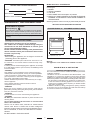
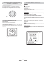
900mm Dual Fuel Upright Manual MODEL GGF90S - Stainless Steel Installation and Operation WHEN YOU CALL FOR SERVICE When you call for service or order parts for your unit, be sure to give: 1. MODEL 2. SERIAL NUMBER 3. COLOUR 4. PART NAME and/or description of problem 5. YOUR FULL NAME, ADDRESS, and HOME TELEPHONE NUMBER and BUSINESS TELEPHONE NUMBER IF APPROPRIATE. RECORD HERE FOR EASY REFERENCE Model Serial Number Colour Installation Date Dealer's Name and Address Servicing shall be carried out only by authorised personnel. GENERAL INFORMATION SECTION FOR THE QUALIFIED TECHNICIAN ENVIRONMENTAL WARNING Waste packaging Do not throw the packaging of your appliance into the dustbin, but pick out the different materials (for instance foil, paperboard, polystyrene) according to the local rules for rubbish elimination. 60 OV E R A L L D I M E N S I O N S This appliance must only be used for the purpose of domestic cooking. Getting to know your new cooker 895 600 h* 750 Thank you for choosing one of our products. Our cookers are of simple, rational design. They are constructed to the best standards to ensure good service and outstanding safety. Please read this manual carefully; it will provide all the advice needed to allow you to obtain the best results from the very first day. ATTENTION: - Before using the appliance, do not forget to remove the protecting parts of the appliance. h* = Adjustment 120 / 175 WARNING -Accessible parts will become hot when in use. To avoid burns and scalds children should be kept away. Warning: This appliance is not suitable to be installed on a base. - WARNING In order to prevent accidental tipping of the appliance, for example by a child climbing onto the open oven door, the stabilizing means must be installed. I N S TA L L AT I O N PROVISION FOR VENTILATION The room where the Cooker is installed should have permanent ventilation as follows: Ventilation must be in accordance with AS5601/2004 - Gas Installations. In general, the appliance should have adequate ventilation for complete combustion of gas, proper flueing and to maintain temperature of immediate surroundings within safe limits. Do not install in a bed-sitting room, a bathroom or shower room. If there is another fuel burning appliance in the same room, a higher level of ventilation will be required, you should consults " the safety requirements". In addition to the above, during prolonged use, opening a window in the same room is recommended. This will avoid the build up of excessive moisture and condensation. - WARNING This appliance is not intended for use by persons (including children) with reduced physical, sensory or mental capabilities, or lack of experience and knowledge, unless they have been given supervision or instruction concerning use of the appliance by a person responsible for their safety. Children should be supervised to ensure that they do not play with the appliance. Young children and infirm persons should not be left unsupervised in the vicinity. - WARNING Before you use the appliance for the first time, check that the plastic films protecting some parts (fascia panel, parts in stainless steel, etc.) have been removed. - WARNING: A steam cleaner is not to be used cleaning this appliances. - WARMING DO NOT place inflammable materials or plastic utensils in the warming drawer. DO NOT SPRAY AEROSOLS IN THE VICINITY OF THIS APPLIANCE WHILE IT IS IN OPERATION. Not for use in marine craft, caravans or mobile homes unless each burner is fitted with a flame safeguard. WHERE THIS APPLIANCE IS INSTALLED IN MARINE CRAFT OR IN CARAVANS, IT SHALL NOT BE USED AS A SPACE HEATER DO NOT MODIFY THIS APPLIANCE. 2 Note: The cooker is fitted with 4 legs for an eventual alignment in height with the furniture ( fig. 1 A ). POSITIONING Important: Fix the chain located next to the gas connection on both sides of the cooker to the wall to prevent the cooker from tilting. Both chains must be securely fixed. Make sure that the wall surface behind the Cooker is noncombustable (will not catch fire). Where a painted surface is adjacent, a fire retardent paint surface is recommended. Wallpaper, wood, or fabric should not be used behind or next to the cooker. Clearances to combustible materials OK "0" mm TO FIX THE COOKER TO THE REAR WALL WARNING - For safety reasons and to prevent tipping of the appliance, these stabilizing means must be installed. The cooker is equipped with 2 chains fixed on each side at the rear of the cooker near the top (see Fig. A). The chains are fitted with spring clips which must be clipped to the screw eyes provided with the cooker. Install the screw eyes as follows : 1. Drill four 6mm holes (position 1 - 2 - 3 - 4) in the wall as in Fig. A. 2. Insert part R into the holes then screw in the screw eyes part G see Fig. B. Note: If the part provided is not suitable for the wall material please use an appropriate device to ensure secure holding of the screw eyes to the wall. 3. Bring the cooker near the wall and clip the chains on the screw eyes as in Fig. C. IMPORTANT: If the cooker is moved for any reason (e.g. maintenance) resulting in the cooker being unclipped from the wall, the cooker must be re-clipped to the wall at the completion of the task. No part of any adjoining wall surface can be made of combustible materials. The protection of combustible materials required by Clause 5.12.1.1 of AS5601-2004 is the fixing of 5 mm thick ceramic tiles to the surface or attaching fire resistant material to the surface and covering with sheet metal with a minimum thickness of 0.4 mm. Clearances to non- combustible materials min "60" mm "0" mm "0" mm 55 mm 55 mm Position 2 chain Position 1 Position 3 non- combustible materials min "60" mm min. 650 mm non- combustible materials If the cooker is being fitted next to cupboards or adjoing wall surfaces, which are within 200mm from the edge of the hob burner and of a suitable non-combustible material as specified in AS5601, then ensure that a distance of at least 6cm is left between the edge of the cooker and the non-combustible material. This gap is to allow plenty of space for the heat produced by the cooker to escape on each side of the cooker. 76 mm "0" mm If the cooker is placed on a base, measures have to be taken to prevent it from slipping off the base. 550 mm min.10 mm min.100 mm Fig. 1 A min. 400 mm min. 650 mm Any adjoining wall surface (side or rear) situated within 200mm of any hob burner must be a suitable non-combustible material from the edge for a height of 150mm for the entire length of the cooker. Any combustible construction above the cooker must be at least 650mm above the maintop. Ensure that a power and gas supply are nearby. The Cooker should be located carefully so that the heat produced by it has plenty of space to escape. The diagram below shows an ideal configuration. NO Position 4 Fig. A Fig. C Fig. B wall wall G G 3 R Hole ELECTRICAL CONNECTION The appliance must be installed by a suitably qualified person in accordance with these instructions and with the requirements of the Australian Wiring Rules AS/NZS 3000. Fixed wired installations are to be provided with suitable isolation means in accordance with the said rules. Any plug socket installed for the purpose of connecting the appliance to supply must be readily accessible when the appliance is installed. Before making the connection, make sure that: 1) the safety circuit-breaker and the electrical system are able to withstand the load of the appliance (see nameplate). 2) the power supply system has an earth connection in good working order in accordance with the regulations in force; IMPORTANT The wires in the mains lead are coloured in accordance with the following code: GREEN & YELLOW.........................................................EARTH BLUE ...........................................................................NEUTRAL BROWN ...............................................................................LIVE Washer Screw Inlet Manifold Extension. Supplied with product. To be fitted by installer Electric power ..1,5 mm2 3 core cable (15 amp. Fuse required). Should conform to local authority requirements. Also refer to rangehood manufacturers recommendations. This appliance is supplied with a plug & cord, simply plug into a 3 pin household socket outlet witch is properly earthed. Regulator Fixed Pipe to Connection Point IT IS RECOMMENDED THAT A SERVICE TAP AND UNION BE FITTED ADJACENT TO THE APPLIANCE INLET TO FACILITATE FUTURE SERVICING. 5 burner models: set the burner pressure to 1kPa for Natural Gas and 2.75kPa for U-LPG with the wok burner operating a full rate. For commissioning of the appliance with the Bromic regulator for Natural Gas , the test point pressure should be 1.00kPa with all burners operating on HIGH. Apply a manometer to the test nipple and reset the regulator if necessary. Do not forget to replace the test nipple screw and to leave the instruction book with the user. This appliance from the factory suitable for NATURAL gas but, if necessary, can be adjusted for U-LPG by authorised person. For the adjustments to U-LPG please operate as specified in the paragraph GAS CONVERSION AND ADJUSTMENT (pag 4). The Gas Connection is male 1/2" BSP and is situated at the right or left, hand rear of the appliance, approximately 40mm from the side The appliance shall be installed by an authorized person in accordance with the manufacturers installation instructions, relevant local fitting regulations, municipal building regulations, the AS5601 code for gas burning appliances and equipment and other relevant statutory code band regulations. If you have some doubts, please contact the authorities for confirmation concerning the characteristics of the gas and electricity output. The appliance is generally preset for natural gas (so no other adjustment is necessary) ensure regulator is fitted for N.G. Ensure that all foreign matter has been cleared from the gas supply line and also purge all air from the gas system. Connect to regulator, tighten and check the installation to ensure no gas leaks occur. WARNING: THIS APPLIANCE MUST BE EARTHED. The flexible mains lead and plug must not be in contact with hot surfaces. GAS CONNECTION Gas Installation must be made in accordance with AS5601; also refer to rangehood manufacturers recommendations. Check gas pressure, note the correct setting from the data plate sealed inside the front appliance drawer . * Installing the Gas Cooker: (Flexible connections are NOT permitted with this appliance) · An inlet manifold extension pipe must be fitted to the appliance. Part supplied in the drawer of the appliance. · Ensure that the pipe is connected using the washer provided and that the bracket is screwed to the appliance as shown in the diagram below. · Fit the supplied pressure regulator. Ensure the arrow is pointing towards the appliance and that the pressure test point is accessible from under the appliance when the product is pushed back into the final position. Push the cooker back and install the stabilizing chains. Connect the appliance inlet manifold to the fixed consumer piping outlet using only fixed piping. This final connection is made when the product is pushed back into position by access under the cooker. VERY IMPORTANT FOR THE INSTALLER Do not attempt to turn or stress threaded elbow of the manifold: you risk damage to this part of the gas appliance which may void the manufacturers warranty. Before Leaving Check all connections for gas leaks. DO NOT use a naked flame for detecting leaks. Ignite all burners to ensure correct operation of gas valves, burners and ignition. Turn gas taps to low flame position and observe stability of the flame. When satisfied with the cooker, please instruct the user on the correct method of operation. In case the appliance fails to operate correctly after all checks have been carried out, refer to the authorised service provider in your area. 4 GAS CONVERSION AND ADJUSTMENT When used with natural gas all burners have been preset at our factory and further adjustment should not be necessary. Conversion kits to other gases are available from the place of purchase. Do not attempt to fit the conversion kit yourself. Conversion to U-LPG gas should only be carried out by an authorized technician. SPECIAL NOTE After installation or any servicing operation, always ensure that the appliance is gas sound and that the components are now operating correctly. Items removed during servicing should be replaced in the reverse order to their removal. GAS ADJUSTEMENTS - change the injectors - adjust the minimum flow When converting from Natural Gas to U-LPG ensure that the NG regulator is removed and replaced with the Test Point Assembly. A gas regulator suitable for a supply pressure of 2.75kPa should be part of the gas tank supply and should be adjusted with the wok burner operating at maximum. REPLACEMENT OF THE INJECTORS When required to operate on other gas replace the injectors in accordance with information referred to in chart below. Always isolate the cooker from the electricity supply, turn off the gas supply temporarily and proceed as follows. TAB. 1 Gas Type Natural Gas Gas Type U - LPG kPa 1.00 kPa kPa 2.75 kPa Jet mm Ø 0.90 1.20 1.50 1.63 1.85 NG Regulator Burners Auxiliary Semi-rapid Rapid Triple Crown Oven Power MJ/h 4.0 7.1 11.0 12.7 15.4 Jet mm Ø 0.53 0.73 0.95 1.00 1.00 Burners Auxiliary Semi-rapid Rapid Triple Crown Oven Power MJ/h 3.7 7.0 11.7 12.7 13.10 TO CHANGE THE WORK-TOP INJECTORS In order to change the work-top injectors, it is necessary to act as follows: remove the grids, remove burners and flame-spreaders (see fig.A), change the injector (see fig.B) and replace it with another one suitable for the new type of gas (see table 1). Reassemble everything in the opposite direction, paying attention to place the flame-spreader in the right way on the burner. A B MINIMUM FLOW ADJUSTMENT FOR HOB-TOP TAPS In order to adjust the minimum flame setting proceed as follows: switch the burner on, and set the knob at the minimum position . Remove the knob from the tap, place a small bladed screwdriver down the centre of the tap shaft (fig. 2A). Attention: on taps with a security valve, the minimum adjusting screw «Z» is on the body of the gas tap (fig. 2B). LP Test point adaptor Z Adjustments, conversions and gas installations must only be carried out by an authorised person. Fig. 2A Fig. 2B Unscrew the adjusting screw in order to increase the flow or screw it to decrease the flow. The correct adjustment is obtained when the flame has a length of about 3 or 4 mm. For U-LPG gas, the adjusting screw must be screwed in thigt. Make sure that the flame does not go out turning quickly from the max. flow to the minimum flow . Refit the knob again. 5 MINIMUM FLOW ADJUSTMENT FOR OVEN THERMOSTAT In order to adjust the minimum, act as follows: switch the burner on turning the knob to the maximum position. Remove the knob and unscrew of some turns the by-pass screw (fig. H). Assemble the knob and let the oven warm up for 15 minutes; after that turn the knob to the minimum position. After having removed the knob once again, making sure that the thermostat rod has not been moved, screw slightly the above mentioned by-pass screw, to obtain a flame of 3 or 4 mm of length. For U-LPG gas, the adjusting screw must be tight screwed. Make sure that the flame does not extinguish passing quickly from the maximum flow to the minimum flow, and closing and opening the oven door (the oven door must be closed softly). Attention: for taps with safety device, the minimum adjusting screw is on the outside of the thermostat rod (fig. H ). TO CHANGE THE OVEN INJECTORS To change the oven injector, it is necessary to act as follows: open the oven door, remove the lower side of the oven (see fig.C), unscrew screw C and disassemble the oven burner (see fig.D). Change the injector (see fig.E) and replace it with another one suitable for the new gas type (see table 1). Re-assemble everything in the opposite direction, paying attention to place the burner in the right way on its rear slot. Fig. H REGULATION OF AIR ADJUSTER (oven burner ) To do this, - Unscrews the screw (A ) in order to rotate the metal ring at the end of the burner (fig L ). In this way, entrace of the air increases or descreases, obtaining a correct flame. Be sure that the flame does not lift or light back or present a yellow colouration . FIG.C C A FIG.D Fig. L Air Adjuster NG - Australia = 8 mm fully open NG - New Zealand = fully open U-LPG = fully open (Once aeration has been adjusted for U-LPG , the aeration shutter must be locked in place using a rivet). FIG.E 6 Always use pans with a flat base diameter, which are well balanced and stable in use, a pan which overhangs the hotplate should not be used. Avoid using old, misshapen pans, or pans which are unstable when placed on a flat surface. Do not use split pans as they are inherently unstable. To save gas, always position pans centrally over the burners and adjust the flames so that they do not lick up the sides of the pan and only the base is heated. Always put lids on saucepans and boil only the amount of liquid you use. When the liquid has boiled adjust the setting to maintain a simmer. Do not light the burner until the pan is in position and turn off the burner before removing the pan. In hard water areas, descale kettles regularly. For safety, keep saucepan handles turned to a safe position so they are out of reach of small children and cannot be accidentally knocked. 2nd SECTION FOR THE USER WARNING: Children should be kept away while the oven or grill is in use since accessible parts become hot. To tunr the burner OFF, turn the control knob clockwise to the OFF setting (marked with a dot ) Automatic electric ignition To turn on a burner, press the knob corresponding to the selected burner and turn it anticlockwise to the maximum position. Keeping the knob pressed, the electric automatic ignition of the burner will be started up. In case there is not electric current, the burner can also be lighted using a match. - Do not use oven base panel as a shelf, make use of the oven shelves. - To avoid splattering and smoke, position collecting tray under the grill with some water in it. - Always turn pan handles to the side or to the back of the hob. If they are left out into the room they can easily be hit or reached by children, this knocking the pan off the hob. - Dont let children sit down or play with the oven door. Do not use the drop down door as a stool to reach above cabinets. - Once your cooking is over make sure to close the main gas supply. WARNING * This appliance is not intended for use by young children or infirm persons without supervision. * Young children should be supervised to ensure that they do not play with the appliance. - WARNING In order to prevent accidental tipping of the appliance, for example by a child climbing onto the open oven door, the stabilizing means must be installed. The small flame indicates the low position. Turn the knob to it after the contents of a pan have boiled. - 1 Minute Tour Be safe Please read the rest of the instruction book which contains important information to help you use the appliance safely and efficiently. Gas and Electricity on Make sure that the gas supply is turned on and that the appliance is plugged in and switched on. The ignitor needs electricity. In case there is no electric current, the burner can also be lighted using a match. The smaller burners are for smaller pans and simmering. Make sure flames are under the pans. Using a lid will help the contents boil more quickly. It is recommended that pans suitable to the size of the burner should be used as follows: BURNERS AUXILIARY SEMI-RAPID RAPIDE TRIPLE CROWN WARNING It is not recommended to press push button for ignition if all the burners are not located in the proper positions. The burner heads, burner skirts and pan supports are removable for better cleaning: Always ensure that the burner skirts and heads are replaced correctly so that the burners function safely and correctly. During the use of the appliance pay attention that water or any liquid does not enter into the appliance through the holes of the burners or around the rods of the valves or the push button electronic lighter. Water or juice will produce dangerous short-circuits and can seriously damage the working of the Hotplate. PANS fl min. fl max 80 mm 120 mm 200 mm 230 mm 160 mm 200 mm 230 mm 260 mm 7 USE OF THE GAS OVEN The first time the oven is used, it may give off acrid smells, caused by the first heating of isolating panels glue surrounding the oven (it is necessary to heat up the oven at the maximum temperature for about 30-40 minutes with closed door). It is something normal, and in case it will occur, wait for the smoke to stop before introducing the food into the oven. The oven is fitted with: a rod shelf for cooking food contained in oven dishes or placed directly on the rod shelf itself, a drip-tray for cooking sweets, biscuits, pizzas, etc., or for collecting juices and fats from food cooked directly on the rod shelf. warnings: do not cook foods on the bottom in the base of the oven. Burner with safety device (according to the models) For burners fitted with safety device, it it necessary to keep on pressing the concerned knob for about 10 seconds after the ignition (fig. 4A). In this way the safety valve will be started up. If for any reason the burner flame goes out, repeat the procedure as described above. GAS OVEN MANUAL IGNITION OF OVEN BURNER To ignite the oven burner, simply insert a match through the opening (fig. 4) and then turn the tap to the maximum setting as shown in figure 3. Fig. 4A Fig. 3 = CLOSED 6 7 0 17 0 25 8 5 = GRILL TAB. C 3 210 = GRILL Pos. 8 = MAXIMUM 2 250°C = MAXIMUM Indicative cooking table (TAB.C). Pos. 1 = MINIMUM 1 140 140°C = MINIMUM 4 = CLOSED FOOD TEMP. °C MEAT ROASTED PORK 185-210 ROASTED BEEF 250 ROASTED VEAL 220 ROASTED LAMB 220 ROASTED HARE 230 ROASTED RABBIT 235 ROASTED TURKEY 220 ROASTED GOOSE 235 ROASTED DUCK 225 ROASTED CHICKEN 235 ROAST-BEEF 200-225 FISH 200-225 Fig. 4 After making sure that the burner has lit properly, gently close the oven door. Automatic electric ignition (according to the models) The oven door must always be completely open, before the burner ignition To ignite the burner, press the knob and turn it anti-clockwise to the maximum position. Keep it pressed to start up the automatic ignition of the burner. In case there is no electric current, the burner can also be lighted using a match. WARNING: Do not operate the ignition for more than 15 seconds. If the burner fails to ignite, leave the oven door open for at least 1 minute before pressing the knob again. 8 FOOD TEMP. °C PASTRY FRUIT CAKE 220 MARGHERITA CAKE 190 BRIOCHES 175 SCONES 235 RING-SHAPED CAKE 190 PUFF-PASTE 200 GRAPES CAKE 200 STRUDEL 180 SAVOIA BISCUIT 290 APPLE FRITTER 200 PUDDING 200 TOAST 250 BREAD 230 USE OF THE ELECTRIC GRILL The electric grill can be operated turning the knob clockwise on position (fig. 5A) and setting the desired temperaure by means of the energy regulator (fig. 5B). The red warning light on the control panel will light up to inform you that the grill is on and the yellow light will stay lit until the temperature is reached, after it will lit intermittently. second level 480 mm m SURFACE BAKING GRILL (480x240) 0m 24 The grill pan should be located on the top oven shelf position and is provided with two detachable grill pan handles which are engaged over the front edge of the pan between the indentations provided. A wire grid is supplied. The grill pan handle should be removed from the grill pan during the grilling operation and only fitted for removal or insertion of the grill pan particularly when hot. Always preheat the grill on full for 3-5 minutes before inserting the food. 250 The user can change the shelves, depending on his personal whishes and on the different food. Geat the oven 5 minutes before introducing the food. 210 To remove the shelves from the oven, pull them forward you, tilt front end upward and pull them out. To replace, ct in the opposite manner as before. 0 14 170 Fig. 5A Bump 5 6 4 1 Pos. 1= 2= 3= 4= 5= 6= °C 50 100 125 150 175 200 Install shelves by locating them in the horizontal guide rails on the oven walls. The raised portion of the shelf is to be facing the rear wall of the oven. 2 3 Fig. 5B Always use the grill with the oven door closed. 9 USE OF THE FAN FUNCTION Some models are fitted with oven fan placed in the central part of the oven cavity. It can be operated turning the knob (fig. 6) on position . Use of the fan assisted gas oven The air which is heated by the gas burner is circulated by the fan which distributes the heat on the food. NOTE: this function must be used with the oven burner and the fan switch both on. This function must be used with the oven door closed. Use of the fan assisted electric grill The air which is heated by the gas burner is circulated by the fan which distributes the heat on the food. The fan assisted grill replaces perfectly the turnspit. You can obtain very good results also with large quantities of poultry, sausage, red meat. This function must be used with the oven thermostat in grill position, the energy regulator in position 4 (fig. 6A) and the fan switch on (fig. 6). This function must be used with the oven door closed. Defrosting with fan The air at ambient temperature is distributed inside the oven for defrosting food very quickly and without proteins adulterations. NOTE: this function must be used with the oven thermostat in position ( 0 ) OFF. Oven light Fan function Fig. 6 Pos. 4 °C 250 3 5 1 210 2 6 1 2 3 4 5 6 50 100 125 150 175 200 100 150 175 200 225 250 0 14 170 Fig. 6A 10 INSTRUCTIONS FOR USE OF CONTROL DEVICES (ACCORDING TO THE MODELS) ELECTRONIC TIMER FOR COOKER (Fig. 9) Functions On The display flashes. MINUTES COUNTERS (Fig. 8) Turn the knob clockwise to set the desired cooking time. The minutes minder can be adjusted from 1 to 60 minutes. A sound signal will inform you that the chosen time is up. Time setting Press the left button. Set the time with buttons + and -. This function remains activated 7 seconds after the last +/operation. 55 5 10 50 Timer setting This function is permanently activated and it will be immediately set with +/- buttons. During setting the units are 10 seconds. During count down the timer takes priority on the display. The units are seconds. The maximum time is 99 minutes. The relay contact (when available) is closed during the count down only. 15 45 20 40 35 30 25 Fig. 8 Reset timer Press + and - buttons together and release + button first. PCI "Campanil"TR 259 Analogic (Fig. 8A) Setting the clock Press the control knob and turn clockwise. Signal The signal after time out will stay 7 minutes if it has not been reset with the + button (one touch only). Alarm programme adjustement Turn the knob clockwise without pressing it in. At the end of the programmed time an alarm will sound. To cancel it, turn the knob to the bell. XI XII Signal frequency When the display shows the time of day, the signal frequency can be selected by pressing the - button. Three different frequencies are selectable. I X II IX III Fig. 9 VIII IV V VI VII Fig. 8A 1 Time of the day 2 Timing and insertion 3 Signal timng and insertion 11 Daily Regular wiping down directly after use prevents dirt from burning on. Clean the appliance with water and a detergent or all purpose cleaner. Avoid using too much water to prevent it entering the burner or ventilation openings. CLEANING Before cleaning the appliance, close the gas stopcock and unplug appliance or disconnect power at the main circuit breaker of the electrical system. Do not clean the appliance surfaces when still hot. Always clean off spillage as quickly as possible to prevent burning on which will make removal more difficult. Wash with a clean cloth soaked in hot soapy water, rinse and dry with a soft cloth. DO NOT USE ABRASIVES. CAUSTIC PASTES OR SPRAYS. COARSE CLEANING PADS OR POWDERS. DO NOT USE EXCESSIVE WATER WHEN CLEANING YOUR OVEN IN ORDER TO AVOID WATER PRESSING THROUGH CLEFTS INTO THE BACK OF CONTROLS PANEL OR OF THE UNIT. Interior: the oven shelf carriers can be removed for easier cleaning. To do this, remove all the shelves and spring off the side carriers (Fig. Q - R ) . Replace in a similar manner. Oven accessories (shelves, trays etc) should be washed in mild detergent solution and should not be treated with abrasives. The oven interior panels should be cleaned with mild detergent solution, mild cream cleaners or a moist soap pad. Install shelves by locating them in the horizontal guide rails on the oven walls. The raised portion of the shelf is to be facing the rear wall of the oven. NOTE: A steam cleaner is not to be used for cleaning this appliance . Pan supports and burners The burner heads can be removed for cleaning. NB Do not drop hot burner caps in cold water. Because of the rapid cooling they might get damaged. Lift off and soak for about 10 minutes in hot water with a little detergent. After having cleaned and washed them, dry them carefully. Make sure that no burner holes are clogged. Clean the burners once a week or more frequently if necessary. Make sure you have reassembled the burners correctly. Pan supports can be washed by hand or in a dishwasher. Remember to remove rubber feet (if fitted) prior to washing. Refit them afterwards. IMPORTANT Do not use excessive water when cleaning the oven and avoid water passing through the fan grill or ducts in the oven back . Avoid letting grease deposit collect around the upper heating element: it will cause smoking and may start a fire. Do not use harsh abrasive cleaners or sharp metal scrapers to clean the oven door glass since they can scratch the surface, which may result in shattering of the glass. Fig. Q burner cap locating pegs notch for electrode in burner head electrode Fig. R For a triple crown burner, make sure head C and covers A and B are properly placed on their seats as figure N and not offcentered as in figure P. B A A B C Fig. N B A Fig. P 12 Disassembly of the worktop must only be done by a qualified service technician DISASSEMBLE OF WORK-TOP In case it is necessary to repair or replace the inside components, act as follows: Remove the grids, remove burners and flame-spreaders (see fig. 13), unscrew the visible screws V placed on the work-top (see fig. 14). Disassemble the work-top by unscrewing the rear screws A (see fig. 15A or 15 B according to the models). In this way it is possible to lift the work-top and to reach the inside components. Removal of oven door In-depth cleaning of the oven becomes more convenient if the door is removed following the instructions below: 1 open the oven door completely. 2 flip the hinge hooks "A" outwards (see fig. 9B). 3 shut the oven door slowly until it reaches hooks "A", making sure these are locked into slots "B" of the oven door, as shown in fig. 9C. Remove the glass FIg. 9A (only for models where present). 4 Using both hands, push the oven door lightly inwards, to enable the door hinges "C" to come away from the slots "D" (see fig. 9D) and pull the door towards you until it is released from the oven. After cleaning it, reposition it correctly following the abovesteps in the reverse order and flipping hooks "A" inwardsbefore you shut the oven door (fig. 9E). V A A Fig. 14 Fig. 13 B A Fig. 9C Fig. 9B C A D Fig. 9D Fig. 9E Fig. 15 A CAUTION: Do not use rough or abrasive materials or sharp metal scrapers to clean the glass doors of the oven since they may scratch the surface and cause the glass to break. WARNINGS Before performing any repair or operation, switch the appliance off and close the gas tap. The manufacturer declines all responsibility for any damage to persons, animals or things caused by failure to observe the rules indicated above. In case it is necessary to repair or replace the inside components, act as follows: WARNINGS Isolate the cooker from the electricity supply before attempting to replace the oven lamp. The oven lamp used is of a special type withstanding high temperatures. To replace it, act as follows: disassemble the protecting glass (A) and replace the burnt lamp with one of the same type. Reassemble the protecting glass. A 13 A GREASING OF TAPS If a tap becomes hard to be turned, grease it using a specific grease withstanding high temperatures. Act as follows: open the work-top and disassemble also the control panel as described on the previous paragraph. Unscrew the two fixing screws from the burner body (see picture) and remove the cone. SOME SAFETY POINT Do not use the appliance as a space heater. If you smell gas Open a window. Do not use any electrical switches. Immediately extinguish naked flames. Isolate appliance from gas mains supplies via the isolation stopcock. Contact local gas authority or emergency services as appropriate. In the event of food fire. Isolate appliance from electric / gas mains supplies if safe to do so. Try to extinguish flames with the appropriate equipment (fire blanket or extinguishing foam). Do not use water on cooking fat / oil fires. If in difficulty call emergency services. Do not store or use flammable products or aerosol containers near the hotplate or burners. Never flambe under an extractor - even if the ventilator is switched off. The high flames can cause fire. TAPS REPLACEMENT Act as follows: open the work-top and disassemble also the control panel as described on the previous paragraph. Unscrew screw nut D of the gas tube supplying the burner. Unscrew screw V fixing the tap to the bridle and remove it (see picture). Note: Every time the tap is replaced, it is necessary to replace the seal gasket too check the connection seal by means of soapy water. D For your safety and that of your children Do not store items that are attractive to children above or near the appliance. Keep children well away from the appliance: do not forget that some parts of the appliance or of the pans become very hot and dangerous during use, and will take time to cool down. When cooking, do not use clothes that could catch fire and cause serious injury. Some Wok cooking pots are unstable. Check with the manufacturer before purchasing. Avoid using unstable and misshapen pans which may tilt easily and pans with a very small base diameter, e.g. milk pans, single egg poachers. The minimum pan diameter recommended is 125mm (5"). Smaller pans will be unstable. Very large pans may cause walls or knobs to overheat. Using pans which are too big may deform the control knobs or discolour the walls. This is not covered by the guarantee. Carefully place all pans centrally over the burners. Always position pan handles safely away from the front of the hotplate and out of danger, particularly from small children. Never leave a chip pan unattended. Pans and kettles with down turned base rims should not be used. Simmering aids such as asbestos or mesh mats are NOT recommended. They will reduce burner performance and could damage the pan supports. Commercially available foil spillage aids are unnecessary on this hotplate. 15 V 7 Clean the cone and its slot by means of a cloth soaked with solvent. Slightly grease the cone with the relevant grease, put it in its slot, and turn it some times. Remove the cone again, remove the excess grease making sure the gas entries are not obstructed by grease residue. Assemble everything carefully in the opposite direction check the connection seal by means of soapy water. 14 OVEN DOES NOT WORK AT ALL First, when the oven is equipped with timer, check appliance is not programmed to turn on later. If it is, turn to manual setting (i.e. hand symbol). If the button or scale on the timer remains in the automatic position after use, the power supply to the oven will be interrupted. Also, check your appliance is switched on at the mains. Next check for an unexpected power strike by switching on adjacent lights etc. Finally, check fuses and plug wiring. If all these prove satisfactory, call engineer. PROBLEM SOLVER Any of the following are considered to be abnormal operation and may require servicing: Yellow tipping of the hob burner flame. Sooting up of cooking utensils. Burners not igniting properly. Burners failing to remain alight. Burners extinguished by oven door. Gas valves, which are difficult to turn. Your Installer should be contacted if you have any problems with the installation. Before you call a service engineer please check if the problem is something you could fix yourself. The cause of the problem is often a simple one. LIGHT BULB DOESNT COME ON Check bulb for looseness or burned out bulb. Note: bulb replacement is not covered by your guarantee. SMOKE COMING FROM OVEN If oven is still relatively new, this problem is invariably due to protective oil on elements. Otherwise, the answer may be oil or fat which has become deposited on the elements during cooking. In either event, continued use should burn away the residues. On future occasions, try to shield food with foil or keep it further away from element, particularly when grilling. THINGS TO TRY BEFORE CALLING FOR AN ENGINEER Burner does not burn well Is the burner dirty or damp? Try cleaning and/or drying the burner. Appliance not suitable for your gas type? Check the identification plate on the hotplate base. Burner does not ignite Do the burners spark when you press the ignition button? If not is the power on? See Checking the power supply section further on. If the power supply is OK then there is probably something wrong with the ignition system. Are the electrode or burner slots blocked by debris? Is the burner dirty or damp? Try cleaning and/or drying the burner. Is the burner trim correctly located? Are the burner caps correctly located? Check that there is not a problem with your gas supply. You can do this by making sure that other gas appliances you may have are working. CLOCK/TIMER DOES NOT WORK Check to be sure range cord is plugged into outlet completely. Check for a blown fuse or tripped circuit breaker. Check for power outage. Check step by step operating Instructions on previous pages. If, after checking through this section, you cannot resolve your problem please call the number on the warranty page in this manual for service and spare parts. When ordering please quote the appliance name, the colour variant and serial number. This information can be found on the data plate sealed inside the front appliance drawer. Pan supports Aluminium pans may cause a metallic marking on the pan supports which does not affect the durability of the enamel and may be cleaned off with a metal cleaner such as Brasso. Checking the power supply First check if the main house fuse or circuit breaker has activated. If its OK, test the power socket with another appliance. If the other appliance works, then unplug the cooker and contact the service agent Power Failure In the event of a failure in the electrical supply the hotplate burners may be lit using a match. Maintenance schedule: To ensure the appliance continues to operate at peak performance, we recommend a routine service call every 2 years for the life of the appliance. Ventilation The use of a gas cooking appliance results in the production of heat and moisture in the room in which it is installed. Ensure that the kitchen is well ventilated: keep natural ventilation holes open or install a mechanical ventilation device, (mechanical extractor hood). Prolonged intensive use of the appliance may call for additional ventilation, for example opening a window, or more effective ventilation, for example increasing the level of mechanical ventilation where present. For more detail see the Installation Instructions. 15 538621 - 29 - 07 - 10