1
2001/2002 MODEL YEAR GENERAL
MOTORS CORPORATION
INFORMATION REGARDING
CONSUMER
INFORMATION
TRUCK-CAMPER
LOADING
PUBLISHED DECEMBER 2000
CHEVROLET MOTOR DIVISION
100 RENAISSANCE CENTER
DETROIT, MICHIGAN 48265-1000
GMC DIVISION
100 RENAISSANCE CENTER
DETROIT, MICHIGAN 48265-1000
Page 1
2001/2002 MODEL YEAR GENERAL MOTORS TRUCKS
CONSUMER INFORMATION TRUCK-CAMPER LOADING
Consumer Information Regulation 575.103 issued by the National Highway Traffic Safety Administration requires
manufacturers of trucks capable of accommodating slide-in camper bodies to provide information concerning proper load
and proper load distribution in truck-camper applications.
This Consumer Information booklet is designed to provide basic information relating to load capabilities of 2001/2002
Model Year General Motors truck models which are adaptable to slide-in camper applications. Information contained
herein is applicable to the truck buyer who already owns a 2001/2002 Model Year General Motors truck or to a
prospective truck purchaser.
The regulation also provides that proper truck-camper loading information is to be maintained in truck dealerships and be
made available to all prospects on request. This booklet relates to the 2001/2002 Model Year General Motors truck
models recommended for slide-in camper applications and is to be used as a consumer information brochure.
Product specifications or data contained herein may change periodically. When a revision of this booklet is supplied to
truck dealers, it is the dealers’ responsibility to make the revised information available to the public.
Chevrolet’s and GMC’s 1500/2500 Series (Silverado/Sierra) Full-Size Pickups feature new redesigned styling for the 1999
Model Year. Some aftermarket products may not fit in the bed of your new vehicle, such as:
• Products manufactured for 2000 Model Year and prior year Chevrolet C/K & GMC Sierra Full-Size Pickups (carryover
design)
• Products manufactured for R/V models built prior to the 1992 Model Year
In addition, for the 2001/2002 Model Year, Chevrolet and GMC will manufacture 1500HD/2500HD/3500 Series
(Silverado/Sierra) Full-Size Pickups that are the new design from the 1999 Model Year. Some aftermarket products may
not fit in the bed of the 2001/2002 Model Year Silverado/Sierra Pickup described above, such as:
• Products manufactured for carryover and previous Chevrolet C/K & GMC Sierra Full-Size Pickups
• Products manufactured for the 1987 Model Year and prior year Chevrolet C/K/Sierra Full-Size Pickups
• Products manufactured for R/V models built prior to 1992 Model Year
For the 2001/2002 Model Year S/T/Sonoma Pickups, some aftermarket products may not fit in the bed of the pickup, such as:
• Products manufactured for S-/T-Series Pickups built prior to 1994 Model Year
Please check the compatibility of any aftermarket product you intend to install on your 2001/2002 Model Year vehicle with
your aftermarket product manufacturer.
All illustrations and specifications contained in this publication are based on the latest product information available at the
time of publication. We reserve the right to discontinue or change at any time, without notice, any colors, optional
equipment, specification and/or body types.
Page 2
TRUCK-CAMPER LOADING
Consumer Information Regulation 575.103 requires manufacturers of trucks capable of accommodating slide-in campers
to specify the vehicles’ Cargo Weight Rating (CWR) and the longitudinal limits within which the center of gravity for the
Cargo Weight Rating should be located.
Cargo Weight Rating (CWR) – means the value specified by the vehicle manufacturer as the cargo-carrying capacity of
a vehicle in kilograms (pounds), exclusive of (minus) the weight of occupants, computed as 68 kilograms (150 pounds)
times the number of designated seating positions.
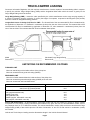
Longitudinal Center of Gravity (CG) Zone for CWR – The forward limit of the recommended CG Zone is determined by
the application of dimension “A” measured in centimeters (inches) from the rear of the truck bed. The rearward limit of the
recommended CG Zone is established by application of dimension “B”, also measured in centimeters (inches) from the
rear of the truck bed. The recommended CG Zone lies between these points.
Model _________________________________________
Calculated Cargo Weight Rating _______________________
Dimension A ____________________________________
Dimension B ________________________________________
LIMITATIONS ON RECOMMENDED CG ZONES
FORWARD LIMIT
Must not extend beyond the inside surface of the pickup box.
Must not exceed the front gross axle rating (GAWR).
REARWARD LIMIT
Must be no farther rearward than the inside surface of the pickup box.
Must not exceed the gross axle weight rating (GAWR) of the rear axle.
Must not exceed rear axle load limits below:
Series
S-10/Sonoma
Rear Axle Load Limits (% of GVWR)
2WD 2,086.6 kg (4,600 lbs) GVWR
2WD 2,222.6 kg (4,900 lbs) GVWR
63%
59%
Silverado/Sierra
1500 (regular/extended cab)
1500HD (crew cab)
2500 (extended cab)
2500HD (regular, extended & crew cab)
3500 (regular, extended & crew cab)
60%
70%
70%
66%
75%
Vehicle CG Identification – All General Motors Corporation trucks that may be suitable for carrying a slide-in camper
incorporate a Truck-Camper Loading information label located on the glove box floor for Silverado/Sierra models, and on
the passenger door for S-/T-10/Sonoma models. The vehicle identification number (VIN) and the as-manufactured Cargo
Weight Rating (CWR) of that vehicle plus the CG limits of dimension “A” and “B” for that vehicle in centimeters (inches)
are included.
Vehicle and Truck-Camper Loading are also discussed at length in the Vehicle Owner’s Manual.
Page 3
TRUCK-CAMPER LOADING
Loading Instructions – When the truck is used to carry a slide-in camper, the total cargo load of the truck consists of the
manufacturer’s camper weight figure, the weight of installed additional camper equipment not included in the
manufacturer’s camper weight figure, the weight of camper cargo and the weight of passengers in the camper. The total
cargo load should not exceed the truck’s Cargo Weight Rating (CWR) and the camper’s center of gravity should fall within
the truck’s recommended center of gravity zone when installed.
Any accessories or other equipment added to this vehicle, after final date of manufacture, must be weighed or have their
weight determined, and the weight deducted from the prescribed Cargo Weight Rating (CWR) of this vehicle. This may
decrease the permissible longitudinal zone of the center of gravity for this vehicle.
The longitudinal center of gravity zone has been determined for the full Cargo Weight Rating of this truck. If a slide-in
camper has a total weight less than the Cargo Weight Rating (CWR), the permissible longitudinal zone of the center of
gravity may be larger. However, individual axle loads should not exceed either of the gross axle weight ratings (GAWR).
Secure loose items to prevent weight shifts that could affect the balance of your vehicle. When the truck-camper is
loaded, drive to a scale and weigh on the front and on the rear wheels separately to determine the axle loads. Individual
axle loads should not exceed either of the gross axle weight ratings (GAWR). The total of the axle loads should not
exceed the gross vehicle weight rating (GVWR). These ratings are given on the vehicle certification label which is located
on the left side of the vehicle, normally on the door latch post or door edge next to the driver. If weight ratings are
exceeded, move or remove items to bring all weights below the ratings.
CAUTION:
The longitudinal center of gravity is only one of the many factors which may affect the overall performance of a
vehicle, including handling, steering and braking. The cargo load should be distributed on both sides of the centerline
as equally as possible. The recommended longitudinal limits for the camper’s center of gravity are based on the
assumption that the vehicle will be operated with reasonable prudence in light of all of the existing conditions. Failure
to do so could result in unsatisfactory vehicle performance and could make the vehicle unsafe to operate.
In this connection, refer to any recommendations by the slide-in camper manufacturer regarding installation and loading of
the camper.
Page 4
TRUCK-CAMPER LOADING
DEFINITION OF TERMS
For the purposes of calculating Truck-Camper Loading in this book, listed below are some common terms and
abbreviations:
Cargo Weight Rating (CWR) – means the value specified by the vehicle manufacturer as the cargo-carrying capacity of
a vehicle in kilograms (pounds), exclusive of (minus) the weight of occupants, computed as 68 kilograms (150 pounds)
times the number of designated seating positions.
Center of Gravity (CG) – point where the mass of a body is concentrated and if suspended at that point would balance
front and rear.
Curb Weight – weight of a vehicle without driver, passengers or cargo but including maximum capacity of fuel, oil, coolant
and other items of standard equipment.
Dimension A & B – front and rear limit of Center of Gravity (CG) zone.
Gross Vehicle Weight Rating (GVWR) – means the value specified by the manufacturer as the loaded weight of a single
vehicle.
Gross Axle Weight Rating (GAWR) – means the value specified by the vehicle manufacturer as the load-carrying
capacity of a single axle system measured at the tire-ground interfaces.
Model Weight – weight of the vehicle with all items of standard equipment, 68 kilograms (150 pounds) per passenger in
each designated seating position and maximum capacity of fuel, oil and coolant.
Payload Rating – is the maximum allowable load (including the weight of the driver and all occupants) that the vehicle
can carry based on all factory-installed equipment on the vehicle.
RPO – Regular Production Option.
Slide-in Camper – means a camper having a roof, floor, and sides, designed to be mounted on and removable from the
cargo area of a truck by the user.
Weight Distribution – the amount of a vehicle’s weight that rests on each axle.
Wheelbase (WB) – the distance from the centerline of the front axle to the centerline of the rear axle.
LIMITATIONS
The following General Motors truck models are not recommended for slide-in camper applications:
• Any pickup model with a Cargo Weight Rating (CWR) of less than 226.8 kg (500 lbs). A statement to this effect is
imprinted on the Truck-Camper Loading information label which states whether that vehicle is recommended for use
with a slide-in camper.
• S-10/Sonoma (2WD) Pickup with 1,905.1 kg (4,200 lbs) GVWR.
• T-10/Sonoma (4x4) Pickup.
• S-/T-10/Sonoma Pickup with 275.1 cm (108.3 in) WB.
• S-/T-10/Sonoma Regular, Extended, or Crew Cab Pickups.
• C/K Avalanche or Escalade EXT pickups.
Note: Silverado/Sierra 1500 Pickups should not be used for larger, cab-over type slide-in campers.
Page 5
TRUCK-CAMPER LOADING
S, C/K, REGULAR, EXTENDED AND CREW CAB PICKUPS
INSTRUCTIONS FOR PROSPECTIVE TRUCK PURCHASERS
VEHICLE SELECTION AND WEIGHT ANALYSIS
For S-10/Sonoma Models
You must order S 10803 – 299.5 cm (117.9 in) WB model with one of the following GVWR Ratings:
S 10803 (2WD)
S 10803 (2WD)
2,086.6 kg (4,600 lbs) GVWR
2,222.6 kg (4,900 lbs) GVWR
Option C5D
Option C5A
If you intend to use a slide-in camper on your S-10/Sonoma Pickup. Record the model on page 3. Record the model
GVWR, front GAWR, and rear GAWR on page 7. These ratings can be found in the GM Dealer World Website on the
Specifications pages, or in GM Autobook.
Silverado/Sierra Models
From the GM Dealer World Website or GM Autobook model selection pages, select the Silverado/Sierra Pickup you
desire. Record this information on page 3. Refer to the Specification section for the selected model. Select the GVWR
you require and note any minimum tire size and chassis equipment requirements for that GVWR. (To approximate the
GVWR you require, add your loaded camper weight to the vehicle curb weight plus the occupants’ weight at 68 kg (150
lbs) per designated seating position.) Record the GVWR and the Gross Axle Weight Rating (GAWR), front and rear
(from the Specifications section), on line 1 of the camper loading worksheet, page 7.
Record the front and rear curb weights of your selected vehicle on line 2, page 7.
Record the front and rear passenger weights on line 3, page 7.
List all factory-installed options you desire, including any options required by your selected GVWR, with their front and
rear weights on the Pickup Camper Loading Worksheet on page 7.
Total the front and rear weights of the vehicle model and options to arrive at the total front and rear weight of the
vehicle. Follow the directions on page 7, lines 5 through 5C to arrive at the adjusted total vehicle weight.
Subtract the adjusted total vehicle weight from the GVWR to arrive at the Cargo Weight Rating (CWR) of your truck.*
Record this information on page 3.
Proceed to page 13 and calculate the center of gravity location limits using front and rear GAWRs, Cargo Weight Rating
(CWR), and front and rear weight of truck as determined above. Record this information on page 3.
*
The addition of any dealer installed or other accessories will reduce the cargo-carrying capacity by the weight of the equipment installed.
Page 6
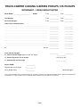
TRUCK-CAMPER LOADING S-SERIES PICKUPS, C/K PICKUPS
WORKSHEET – CARGO WEIGHT RATING
Model GVWR ________________________
GAWR
Front _____________
Rear ____________
Curb Weights:
Front _____________
Rear ____________
Passenger Weights:
Front _____________
Rear ____________
Other factory-installed options:
..............................................................................................................
_____________
____________
..............................................................................................................
_____________
____________
..............................................................................................................
_____________
____________
..............................................................................................................
_____________
____________
..............................................................................................................
_____________
____________
..............................................................................................................
_____________
____________
..............................................................................................................
_____________
____________
..............................................................................................................
_____________
____________
..............................................................................................................
_____________
____________
4a.
_____________
____________
_____________
____________
TOTALS
Front and Rear Weights:
5a. Vehicle sub-total weight (add front and rear weight)
______________
5b. Add 22.7 kg (50 lbs) for all models*
+22.7 kg (50 lbs)
5c. Adjusted total vehicle weight:
______________
Vehicle GVWR:
Adjusted total vehicle weight
Cargo Weight Rating
_____________
(- ___________ )
_____________
Record on Page 3.
If your vehicle is available, drive to a scale and weigh, with occupants, full fuel tank, and other factory-installed options to determine the adjusted total
vehicle weight. You will then be able to use your actual total vehicle weight and not have to add the 22.7 kg (50 lbs).
Page 7
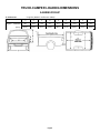
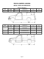
TRUCK-CAMPER LOADING DIMENSIONS
S-SERIES PICKUP
S-10/Sonoma
Long Box
Long Box (Model S-10/Sonoma 10803)
A
B
C
D
E
F
G
H
J
Centimeters
132.1
102.5
172.5
42.7
92.1
237.0
143.8
222.5
143.8
(Inches)
(52.0")
(40.4")
(67.9")
(16.8")
(36.3")
(93.3")
(56.6")
(87.6")
(56.6")
Page 8
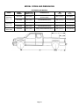
TRUCK-CAMPER LOADING DIMENSIONS
C/K SERIES PICKUP
FLEETSIDE/WIDESIDE
OPTION E63
Short Box
Long Box
Short Box (Models Silverado/Sierra 15703, 15743, 15753, 25743, 25753)
Long Box (Models Silverado/Sierra 15903, 15953, 25903, 25953, 35903, 35943, 35953)
A
B
C
D
E
F
G
H
J
K
L
Centimeters
157.2
127.3
198.9
49.6
107.3
212.0
162.1
199.8
157.2
–
202.5
(Inches)
(61.9")
(50.1")
(78.3")
(19.5")
(42.2")
(83.5")
(63.8")
(78.7")
(61.9")
–
(79.7")
Centimeters
157.4
127.3
198.9
49.6
107.3
260.0
162.0
247.8
157.4
244.1
202.5
(Inches)
(62.0")
(50.1")
(78.3")
(19.5")
(42.2")
(102.4")
(63.8")
(97.7")
(62.0")
(96.1")
(79.7")
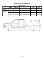
SPORTSIDE
Short Box (Model Silverado/Sierra 15703, 15753)
OPTION E62
Short Box
A
B
C
D
E
F
G
H
J
Centimeters
130.0
131.2
199.4
49.9
107.3
211.3
124.6
199.7
124.6
(Inches)
(51.1")
(51.7")
(78.5")
(19.6")
(42.2")
(83.2")
(49.1")
(78.6")
(49.1")
Page 9
TRUCK-CAMPER LOADING
MODEL CODES AND DIMENSIONS
REGULAR CAB MODELS
SERIES
MODEL
NUMBER
PICKUP BOX
LENGTH cm (ft)
PICKUP STYLE
WB
cm (in)
“C”*
cm (in)
S-10/Sonoma
S 10803
225.6 (7.4')
Fleetside/Wideside (E63)
299.5 (117.9")
108.5 (42.9")
SERIES
MODEL
NUMBER
PICKUP BOX
LENGTH cm (ft)
PICKUP STYLE
WB
cm (in)
“C”*
cm (in)
C/K 15703
197.6 (6.5')
Fleetside/Wideside (E63)
Sportside (E62)
302.3 (119.0")
98.8 (38.9")
C/K 15903
245.6 (8.0')
Fleetside/Wideside (E63)
337.8 (133.0")
111.3 (43.8")
Silverado/
Sierra 2500
C/K 25903
245.6 (8.0')
Fleetside/Wideside (E63)
337.8 (133.0")
111.3 (43.8")
Silverado/
Sierra 3500
C/K 35904
245.6 (8.0')
Dually Fleetside/Wideside (E63)
337.8 (133.0")
111.3 (43.8")
Silverado/
Sierra 1500
Page 10
MODEL CODES AND DIMENSIONS
EXTENDED CAB MODELS
SERIES
Silverado/
Sierra 1500
Silverado/
Sierra 2500
Silverado/
Sierra 3500
MODEL
NUMBER
PICKUP BOX
LENGTH cm (ft)
PICKUP STYLE
WB
cm (in)
“C”*
cm (in)
C/K 15753
197.6 (6.5')
Fleetside/Wideside (E63)
Sportside (E62)
364.5 (143.5")
98.8 (38.9")
C/K 15953
245.6 (8.0')
Fleetside/Wideside (E63)
400.0 (157.5")
111.3 (43.8")
C/K 25753
197.6 (6.5')
Fleetside/Wideside (E63)
364.5 (143.5")
98.8 (38.9")
C/K 25953
245.6 (8.0')
Fleetside/Wideside (E63)
400.0 (157.5")
111.3 (43.8")
C/K 35953
245.6 (8.0')
Dually Fleetside/Wideside (E63)
400.0 (157.5")
111.3 (43.8")
Page 11
MODEL CODES AND DIMENSIONS
CREW CAB MODELS
SERIES
MODEL
NUMBER
PICKUP BOX
LENGTH cm (ft)
PICKUP STYLE
WB
cm (in)
“C”*
cm (in)
Silverado/
Sierra 1500
C/K 15743
198.1 (6.5')
Fleetside/Wideside (E63)
388.6 (153.0")
98.8 (38.9")
C/K 25743
198.1 (6.5')
Fleetside/Wideside (E63)
388.6 (153.0")
98.8 (38.9")
C/K 25943
243.8 (8.0')
Fleetside/Wideside (E63)
424.2 (167.0")
111.3 (43.8")
C/K 35943
243.8 (8.0')
Dually Fleetside/Wideside (E63)
424.2 (167.0")
111.3 (43.8")
Silverado/
Sierra 2500
Silverado/
Sierra 2500
* Dimensions “C” is the distance from the centerline of the rear axle to the end of the pickup box floor.
Dimension A and B can be calculated by using formula on page 13.
Page 12
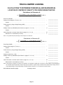
TRUCK-CAMPER LOADING
CALCULATIONS TO DETERMINE FORWARD (A) AND REARWARD (B)
LOCATION OF CENTER OF GRAVITY FOR CARGO WEIGHT RATING
Calculations for Dimension A
A=
- (1.05 x Front Weight* of Truck)
{Front GAWRCargo
}x WB +C
Weight Rating
Enter Front GAWR...........................................................................................................
Subtract Front Weight* of Truck x 1.05..............................................................................
__________________
-
__________________
Answer......................................................................................................................
__________________
Divide Answer by Cargo Weight Rating (CWR) .................................................................
÷ __________________
Answer......................................................................................................................
__________________
Multiply Answer by Wheelbase (See Charts on pages 10, 11 or 12) ...................................
x __________________
Answer......................................................................................................................
__________________
+C __________________
Dimension A in centimeters (in inches) ....................................................................... = __________________
Add C Dimension to Answer (See Charts on pages 10, 11 or 12) .......................................
Note: If “A” is greater than pickup box length, use box length for “A” dimension.
Calculations for Dimension B
B=
- (1.1 x Front Weight* of Truck)
{1- Front GAWR
}x WB + C
Cargo Weight Rating
Enter Rear GAWR...........................................................................................................
Subtract Rear Weight* of Truck x 1.1................................................................................
__________________
-
__________________
Answer......................................................................................................................
__________________
Divide Answer by Cargo Weight Rating (CWR)..................................................................
÷ __________________
Answer......................................................................................................................
__________________
- __________________
Multiply Answer by Wheelbase (See Charts on pages 10, 11 or 12) .................................... x __________________
Subtract Answer from 1.000 .............................................................................................
Answer......................................................................................................................
__________________
+C __________________
Dimension B in centimeters (in inches)........................................................................ = __________________
Add C Dimension to Answer (See Charts on pages 10, 11 or 12)........................................
Note: If “B” dimension is negative, use 0 (zero) for “B” dimension. If “B” dimension is greater than “A” dimension, camper usage is not recommended at
the Calculated Cargo Weight Rating. Camper usage may be possible for a lighter camper. Substitute known specific camper weight (less than
Cargo Weight Rating) for Cargo Weight Rating in calculations above to determine “A” to “B” range for that specific camper.
Record dimension A and B on page 3.
*From page 7 line 4a.
Page 13
CHEVROLET MOTOR DIVISION
100 RENAISSANCE CENTER
DETROIT, MICHIGAN 48265
PONTIAC • GMC DIVISION
100 RENAISSANCE CENTER P.O. BOX 431301
DETROIT, MICHIGAN 48243-7301
Page 14
PAGE
SPECIAL APPLICATIONS
15
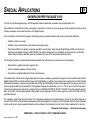
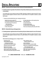
SNOWPLOW PREP PACKAGE (VYU)
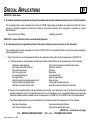
The chart on the following page shows GMTG approved models available with snowplow prep package-option VYU.
General Motors recommends that when a snowplow is mounted on a vehicle, only one passenger should accompany the driver. More
than one passenger may exceed Front Gross Axle Weight Ratings.
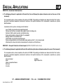
Prior to installing a front mounted snowplow, the following process should be followed and necessary information obtained.
•
Establish vehicle curb weight
•
Establish chassis manufacturer’s front and rear axle weight ratings
•
Chevrolet and GMC truck dealers can provide availability, specifications, Gross Vehicle Weight Ratings (GVWR), and Front and
Rear Gross Axle Weight Ratings (FGAWR/RGAWR). For vehicles already built, this information can be found on the certification
label installed on driver’s door/door frame or provided on the cover of the Incomplete Vehicle Document.
The following information should be obtained and provided by the manufacturers of snowplows and salt spreaders:
•
Specifications, weights and center of gravity data
•
Vehicle installation guidelines and instructions
•
Calculation of weight distribution for the front and rear axles
The loaded vehicle with driver, passenger, aftermarket accessories, snowplows, spreader, and cargo must not exceed the Gross Vehicle
Weight Rating (GVWR), and Front and Rear Gross Axle Weight Ratings. In addition, the completed curb weight vehicle, with all installed
aftermarket accessories, snowplow, and spreader, and with 400 lbs. distributed in the driver-passenger area of the vehicle, must have a
center of gravity location that is located within the trapezoid formed by the coordinates A, B, C, D, H1 & H2, plus it must be to the rear of
vertical line E and forward of vertical line F as defined in the ALLOWABLE CENTER OF GRAVITY CHARTS. If the center of gravity location
does not fall within the specified trapezoid, ballast weight may be required to shift the center of gravity location until it falls within the
specified trapezoid.
The snowplow manufacturer and the installer of the aftermarket equipment should determine the amount of rear ballast required to
ensure that the vehicle, with the attached snowplow and aftermarket equipment, complies with the Allowable Center of Gravity Trapezoid
and the resulting front and rear weight distribution ratio as defined in the Allowable Center of Gravity Charts published in this manual.
(Snowplow Prep Package — continued on next page)
SNOWPLOW — ONLY ON THE C/K, UTILITY AND CAB CHASSIS
Special Applications – 2001
PAGE
SPECIAL APPLICATIONS
16
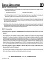
(Snowplow Prep Package — continued from previous page)
Ballast Compensating Weight
The use of rear ballast weight may be required to prevent exceeding the Gross Axle Weight Rating of the front axle. The use of rear ballast
weight may be required to ensure that the center of gravity location of the completed vehicle, with the attached snowplow and other
installed equipment, complies with the Allowable Center of Gravity Trapezoid and the resulting front and rear weight distribution ratio,
even though the actual front weight may be less than the Gross Axle Weight Rating of the front axle. In either case, the rear
ballast weight should be securely attached in the cargo box or behind the rear axle of the vehicle in a manner which prevents it from
moving during driving and stopping.
To help avoid personal injury, refer to Z-height setting procedure
before adjusting torsion bars. If torsion bars are adjusted for
aftermarket equipment, be sure to return them to specification
when the equipment is removed. Otherwise, a front shock
absorber may dislodge and damage a front brake line. This could
result in an accident when minimum stopping distances are
required.
SNOWPLOW — ONLY ON THE C/K, UTILITY AND CAB CHASSIS
Special Applications – 2001
PAGE
SPECIAL APPLICATIONS
17
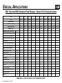
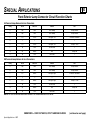
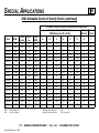
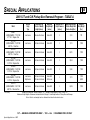
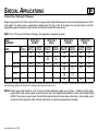
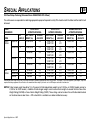
2001 Chevrolet/GMC Snowplow Prep Package – Option VYU, Pickup
Model
Cab
Wheelbase Inches
P.U. Box Length feet
GVWR lb. (option code)
GAWR lb. — Frt.
Engine Availability with VYU:
Vortec 8.1L Gasoline V8 Engine
Duramax 6.6L Diesel V8 Engine
Vortec 4800 V8 Gasoline
Vortec 6000 V8 Gasoline
Vortec 6000 V8 Gasoline
Base (B) Equipment Includes:
Battery 600 CCA (*)
Provisions for Rear Back-Up Lighting
Generator 105-Amps
LT 245/75R16E HWY/OOR Tires
LT 215/85R16D HWY/OOR Tires
Snowplow Prep Pkg. Includes:
Upgrade Front Torsion Bar
External Engine Oil Cooler LQ4 only
Generator 130-Amps
Provision for Roof Mntd. Emergency Light
Transmission Cooler (air to oil) Auto only
42mm Hole FOD with Rubber Grommet
Opt. Code
L18
LB7
LR4
LM7
LQ4
—
—
K68
—
—
VYU
F60
KC4
KG8
TRW
KNP
—
K15703
Regular
119
6.5
6100(C5M)
3925
K15903
Regular
133
8
6400(C7H)
3925
K25753
Extended
143.5
6.5
9200(6CW)
4800
K25743
Crew
143.5
6.5
9200(6CW)
4800
K25903
Regular
133
8
9200(6CW)
4800
K25943
Crew
157.5
8
9200(6CW)
4800
N/A
N/A
A
A
N/A
N/A
N/A
A
A
N/A
A
A
—
—
B
N/A
N/A
—
—
B
A
A
—
—
B
N/A
N/A
—
—
B
A
N/A
—
—
B
A
A
—
—
B
A
N/A
—
—
B
N/A
N/A
—
—
B
B
B
B
—
—
B
B
B
—
—
B
B
B
B
—
B
B
B
B
—
B
B
B
B
—
B
B
B
B
—
B
B
B
B
—
B
B
B
—
B
B
B
B
—
—
B
B
B
—
—
X
N/A
X
X
X
X
X
N/A
X
X
X
X
X
X
X
X
R
X
X
X
X
X
R
X
X
X
X
X
R
X
X
X
X
X
R
X
X
X
X
X
R
X
X
X
X
X
X
X
X
X
X
X
X
X
X
X
X
X
X
X
(*) Trucks with LB7 (Diesel Engine) come with dual 770 CCA batteries (TQ3) as base equipment
K25953
K35903
K35953
K35943
Extended
Regular
Extended
Crew
157.5
133.0
157.5
167.0
8
8
8
8
9200(6CW) 11400(C7W) 11400(C7W) 11400(C7W)
4800
4800
4800
4800
B – base vehicle / A – available / X – included in package / Y – included where applicable / N/A – not available on this model / R – required on this model
SNOWPLOW — ONLY ON THE C/K, UTILITY AND CAB CHASSIS
Special Applications – 2001
(continued on next page)
PAGE
SPECIAL APPLICATIONS
18
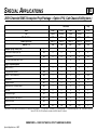
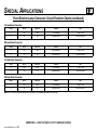
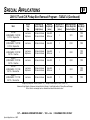
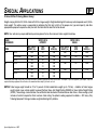
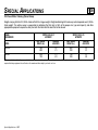
2001 Chevrolet/GMC Snowplow Prep Package – Option VYU, Pickup (continued)
Model
Cab
Wheelbase Inches
P.U. Box Length feet
GVWR lb. (option code)
GAWR lb. — Frt.
Snowplow Prep Pkg. Includes: (cont.)
Fwd. Lamp Harness with In-Line Connector
Mntg. Location for Snowplow Controls
High Air Flow Front Bumper Impact Strip
Dual Rear Wheels
LT 245/75R16E ALS/OOR TIRES (60 PSI)
LT 215/85R16E HWY/OOR TIRES (70 PSI)
Suggested Optional Equipment:
Locking Differential, Rear Axle
Battery 770 CCA (*)
Batteries – 770 CCA & 600 CCA (*)
Back-up Alarm
Engine Block Heater
Replacement Floor Covering HD Rubber
Tow Hooks
Rear Window Defogger
Sliding Rear Window not avail. with C49
Skid Plate “Off Road”
Trailer Hitch
K15703
Regular
119
6.5
6100(C5M)
3925
K15903
Regular
133
8
6400(C7H)
3925
K25753
Extended
143.5
6.5
9200(6CW)
4800
K25743
Crew
143.5
6.5
9200(6CW)
4800
K25903
Regular
133
8
9200(6CW)
4800
K25943
Crew
157.5
8
9200(6CW)
4800
VYU
—
—
VG3
—
—
—
X
X
X
N/A
—
—
X
X
X
N/A
—
—
X
B
X
N/A
R
—
X
B
X
N/A
R
—
X
B
X
N/A
R
—
X
B
X
N/A
R
—
X
B
X
N/A
R
—
X
B
X
B
—
R
X
B
X
B
—
B
X
B
X
B
—
B
G80
7Y9
8B0
8S3
K05
BG9
V76
C49
A28
NZZ
VR4
A
A
A
A
A
A
B
A
A
A
A
A
A
A
A
A
A
B
A
A
A
A
A
A
A
A
A
A
B
A
A
A
A
A
A
A
A
A
A
B
A
A
A
A
A
A
A
A
A
A
B
A
A
A
A
A
A
A
A
A
A
B
A
A
A
A
A
A
A
A
A
A
B
A
A
A
A
A
A
A
A
A
A
B
A
A
A
A
A
A
A
A
A
A
B
A
A
A
A
A
A
A
A
A
A
B
A
A
A
A
(*) Trucks with LB7 (Diesel Engine) come with dual 770 CCA batteries (TQ3) as base equipment
K25953
K35903
K35953
K35943
Extended
Regular
Extended
Crew
157.5
133.0
157.5
167.0
8
8
8
8
9200(6CW) 11400(C7W) 11400(C7W) 11400(C7W)
4800
4800
4800
4800
B – base vehicle / A – available / X – included in package / Y – included where applicable / N/A – not available on this model / R – required on this model
SNOWPLOW — ONLY ON THE C/K, UTILITY AND CAB CHASSIS
Special Applications – 2001
PAGE
SPECIAL APPLICATIONS
19
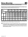
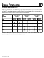
2001 Chevrolet/GMC Snowplow Prep Package – Option VYU, Cab Chassis/Utility
Model
Cab
Wheelbase Inches
GVWR lb. (option code)
GAWR lb. — Frt.
Engine Availability with VYU:
Vortec 8.1L Gasoline V8 Engine
Duramax 6.6L Diesel V8 Engine
Vortec 6000 V8 Gasoline
Base (B) Equipment Includes:
Battery 600 CCA (*)
Provisions for Rear Back-Up Lighting
Generator 105-Amps
LT 215/85R16D HWY/OOR Tires
Snowplow Prep Pkg. Includes:
Upgrade of front torsion bar
External Eng. Oil Cooler LQ4 only
Generator 130-Amps
Provision for Roof Mntd. Emergency Light
Transmission Cooler (air to oil) Auto only
42mm Hole FOD with Rubber Grommet
Fwd Lamp Harness with In-Line Connector
Mntg. Location for Snowplow Controls
K36003
Regular
137.0
12000 (C7L)
4800
Opt. Code
L18
LB7
LQ4
—
—
K68
—
VYU*
F60
KC4
KG8
TRW
KNP
—
—
—
Cab Chassis
K36053
K36403
Extended
Regular
161.5
161.5
12000 (C7L)
12000 (C7L)
4800
4800
K36453
Extended
185.5
12000 (C7L)
4800
Utility
K25906
—
130.0
8600 (C6P)
4500
A
A
B
A
N/A
B
A
N/A
B
N/A
N/A
B
A
A
B
B
B
B
B
B
B
B
—
B
B
B
—
B
B
B
—
B
N/A
N/A
—
Y
X
X
X
X
X
X
B
Y
X
X
X
X
X
X
B
Y
X
X
X
X
X
X
B
Y
X
X
X
X
X
X
B
X
X
B
X
N/A
—
—
—
(*) Trucks with LB7 (Diesel Engine) come with dual 600 CCA batteries as base equipment
B – base vehicle / A – available / X – included in package / Y – included where applicable / N/A – not available on this model
* Options CF5, WX9, 5G4, Z55, and Exp. Are excluded on the K25906 when VYU is ordered
SNOWPLOW — ONLY ON THE C/K, UTILITY AND CAB CHASSIS
Special Applications – 2001
(continued on next page)
PAGE
SPECIAL APPLICATIONS
20
2001 Chevrolet/GMC Snowplow Prep Package – Option VYU, Cab Chassis/Utility (cont.)
Model
Cab
Wheelbase Inches
GVWR lb. (option code)
GAWR lb. — Frt.
Snowplow Prep Pkg. Includes: (cont.)
High Air Flow Frt. Bump Impact Strip
Dual Rear Wheels
LT 215/85R16E HWY/OOR TIRES (70 PSI)
Suggested Optional Equipment:
Battery 770 CCA (*)
Locking Differential, Rear Axle
Batteries – 770 CCA & 600 CCA (*)
Back-up Alarm
Engine Block Heater
Replacement Floor Covering HD Rubber
Tow Hooks
Rear Window Defogger
Sliding Rear Window not avail. with C49
Skid Plate “Off Road”
Trailer Hitch
K36003
Regular
137.0
12000 (C7L)
4800
Cab Chassis
K36053
K36403
Extended
Regular
161.5
161.5
12000 (C7L)
12000 (C7L)
4800
4800
K36453
Extended
185.5
12000 (C7L)
4800
Utility
K25906
—
130.0
8600 (C6P)
4500
VYU*
VG3
RO5
—
B
B
R
B
B
B
B
B
B
B
B
B
B
N/A
—
7Y9
G80
8B0
8S3
K05
BG9
V76
C49
A28
NZZ
VR4
A
A
A
A
A
A
B
A
A
A
N/A
A
A
A
A
A
A
B
A
A
A
N/A
A
A
A
A
A
A
B
A
A
A
N/A
A
A
A
A
A
A
B
A
A
A
N/A
A
A
N/A
N/A
—
—
A
A
—
A
A
(*) Trucks with LB7 (Diesel Engine) come with dual 600 CCA batteries as base equipment
B – base vehicle / A – available / X – included in package / Y – included where applicable / N/A – not available on this model
* Options CF5, WX9, 5G4, Z55, and Exp. Are excluded on the K25906 when VYU is ordered
SNOWPLOW — ONLY ON THE C/K, UTILITY AND CAB CHASSIS
Special Applications – 2001
PAGE
SPECIAL APPLICATIONS
21
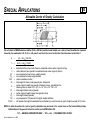
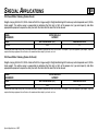
Allowable Center of Gravity Calculation
C.G. of vehicle in FMVSS unladen condition (Curb + 400 lbs.) must be inside shaded area – that is, it must be within the trapezoid
formed by the coordinates A, B, C, D, H1, & H2, plus it must be to the rear of vertical line E and forward of vertical line F.
d
=
h
=
d
h
Wrc
Wrb
W.B.
Wt
=
=
=
=
=
=
h1
=
Wc
h2
Wb
150
10,000
=
=
=
=
=
(Wrc + Wrb + 150) W.B.
Wt
(h1Wc + h2Wb + 10,000)
Wt
horizontal distance from front wheels to completed vehicle center of gravity (inches)
vertical distance from ground to completed vehicle center of gravity (inches)
rear component of bare chassis weight (pounds)
rear component of body weight (pounds)
vehicle wheelbase (inches)
total weight of chassis, body (pounds) plus 400 pounds
center of gravity height from ground of the bare chassis, selected from the
following value by model: C/K = 28”
total weight of bare chassis (pounds)
center of gravity height of body from ground (inches)
total weight of body (pounds)
rear component of 400 pounds (from lightly loaded definition)
400 pounds (from lightly loaded definition) multiplied by its vertical center of gravity height (assumed) of 25 inches
NOTE: An alternate method of center of gravity calculation may be found in the current issue of the General Motors Body
Builders Book in the general instruction section and in SVIE Bulletin #39.
SNOWPLOW — ONLY ON THE C/K, UTILITY AND CAB CHASSIS
Special Applications – 2001
PAGE
SPECIAL APPLICATIONS
22
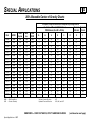
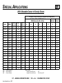
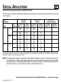
2001 Allowable Center of Gravity Charts
Incomplete, Pickup Box Removal, or Snowplow Prep Package Vehicles
Coordinates of Allowable C/G Variation at
Forward Rearward
FMVSS Unladen (Curb Wt. + 400 lbs.)
C/G Limit C/G Limit
Model
GVWR
C25906
K25906
C15903
C15753
C15953
K15903
K15753
K15953
C15743
K15743
C25903
C25903
C25753
C25743
C25953
C25943
K25753
K25903
8600
8600
6400
6200
6400
6400
6400
6400
8600
8600
8600
9200
9200
9200
9200
9200
8600
9200
SRW
DRW
C/G
= Single Rear Wheel
= Dual Rear Wheel
= Center of Gravity
Brake
System
JH6
JH6
JC5
JC5
JC5
JC5
JC5
JC5
JH6
JH6
JH6
JH6
JH6
JH6
JH6
JH6
JH6
JH6
Wheel
base
130.0
130.0
133.0
143.5
157.5
133.0
143.5
157.5
153.0
153.0
133.0
133.0
143.5
153.0
157.5
167.0
143.5
133.0
SRW
DRW
SRW
SRW
SRW
SRW
SRW
SRW
SRW
SRW
SRW
SRW
SRW
SRW
SRW
SRW
SRW
SRW
SRW
SRW
H1
H2
A
B
C
D
E
F
12
12
12
12
12
12
12
12
12
12
12
12
12
12
12
12
12
12
48
48
48
48
48
48
48
48
48
48
48
48
48
48
48
48
48
48
36
36
34
37
42
34
37
42
51
51
36
45
48
51
52
55
39
45
63
63
59
64
68
59
64
68
77
77
59
71
74
77
78
80
64
71
70
70
70
76
79
70
76
79
61
61
70
54
58
61
63
66
76
54
97
97
95
102
105
95
102
105
88
88
93
81
84
88
89
93
100
81
43
43
44
48
52
44
48
52
51
51
44
45
48
51
52
55
47
45
97
97
95
102
105
95
102
105
88
88
93
81
84
88
89
93
100
81
Brake Systems:
Vacuum Powered Boosters
Hydraulic Powered Boosters
JC5
JH5, JH6, and JH7
SNOWPLOW — ONLY ON THE C/K, UTILITY AND CAB CHASSIS
Special Applications – 2001
(continued on next page)
PAGE
SPECIAL APPLICATIONS
23
2001 Allowable Center of Gravity Charts (continued)
Incomplete, Pickup Box Removal, or Snowplow Prep Package Vehicles
Coordinates of Allowable C/G Variation at
Forward Rearward
FMVSS Unladen (Curb Wt. + 400 lbs.)
C/G Limit C/G Limit
Model
GVWR
K25753
K25743
K25953
K25943
C35903
C35953
C35943
K35903
K35953
K35943
C36003
C36053
C36403
C36453
K36003
K36053
K36403
K36453
9200
9200
9200
9200
11,400
11,400
11,400
11,400
11,400
11,400
11,400
11,400
11,400
11,400
12,000
12,000
12,000
12,000
SRW
DRW
C/G
= Single Rear Wheel
= Dual Rear Wheel
= Center of Gravity
Brake
System
JH6
JH6
JH6
JH6
JH7
JH7
JH7
JH7
JH7
JH7
JH7
JH7
JH7
JH7
JH7
JH7
JH7
JH7
Wheel
base
143.5
153.0
157.5
167.0
133.0
157.5
167.0
133.0
157.5
167.0
137.0
161.5
161.5
185.5
137.0
161.5
161.5
185.5
SRW
DRW
SRW
SRW
SRW
SRW
DRW
DRW
DRW
DRW
DRW
DRW
DRW
DRW
DRW
DRW
DRW
DRW
DRW
DRW
H1
H2
A
B
C
D
E
F
12
12
12
12
12
12
12
12
12
12
12
12
12
12
12
12
12
12
48
48
48
48
48
48
48
48
48
48
48
48
48
48
48
48
48
48
48
51
52
55
41
48
50
41
48
50
43
49
49
55
43
49
49
55
74
77
78
80
59
65
68
59
65
68
60
67
67
73
60
67
67
73
58
61
63
66
99
116
123
99
116
123
102
119
119
136
102
119
119
136
84
88
89
93
109
128
135
109
128
135
112
131
131
148
112
131
131
148
48
51
52
55
41
48
50
41
48
50
43
49
49
55
43
49
49
55
84
88
89
93
109
128
148
109
128
148
112
131
131
148
112
131
131
148
Brake Systems:
Vacuum Powered Boosters
Hydraulic Powered Boosters
JC5
JH5, JH6, and JH7
SNOWPLOW — ONLY ON THE C/K, UTILITY AND CAB CHASSIS
Special Applications – 2001
PAGE
SPECIAL APPLICATIONS
24
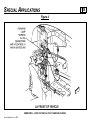
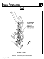
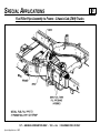
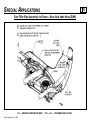
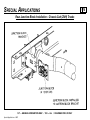
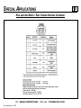
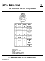
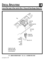
Snowplow Prep Package (VYU) Electrical Provisions
Emergency Roof-Mounted Lamp Switch This provision includes a dash-mounted switch (see Figure 1), a relay, and wiring which is
routed up along the Left Hand B pillar that terminates at the roof as coiled blunt cut wires (see Figure 2). There are two blunt cut 12-gauge
(3.0 mm2) wires, one is Brown (roof-mounted lamp power), it is controlled by the dash-mounted switch through the relay, the other is
Black (ground). The Brown power wire is protected by the 30-Amp SEO 2 fuse which is located in the Underhood Electrical Center.
130-Amp Generator The AD244 130-Amp generator will be equipped on all VYU pickup trucks except those having the Vortec 4300 V6
(L35) engine. The AD244 generator is an upgrade from the AD230 105-Amp generator which comes as standard equipment.
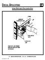
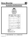
Accessory Harness Grommet Trucks will come equipped with a predrilled 42mm pass-through hole located on the dash panel on the
left hand side of the vehicle. The hole will be sealed with a grommet (see Figure 3) which can be used by the upfitter for pass-through
wiring. To use the grommet (part# 15336702), the upfitter slices off the tape tab end (in engine compartment) of the grommet and then
spreads it open to pass wiring through.
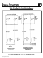
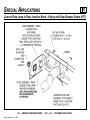
Forward Lamp Harness In-Line Connector The forward lamp wiring harness will have a set of mating eight cavity connectors on both
the left and right hand side of the vehicle (see Figures 4 & 5). The upfitter will be able to disconnect the in-line connectors which will allow
interfacing with the forward lamp circuits (Front Parklamp, Turn Signal and DRL). The headlamp circuits must be accessed from the
headlamp connectors. Circuit function charts of these connectors are on page 10. Connector face diagrams of the connectors are on
pages 11 and 12. A parts list of these connectors is provided on page 13.
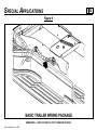
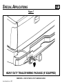
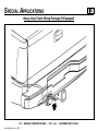
Backup Lamp Power Feed Although this feature is standard on the All New C/K pickup trucks, it should be pointed out that a backup
lamp power feed is provided at the rear of the vehicle through the trailer wiring harness. This circuit is protected by the 10-Amp TRLR
B/U fuse which is located in the Underhood Electrical Center. On vehicles with Light Duty Trailer Wiring (see Figure 6) which comes
standard, this circuit can be accessed through the Light Green trailer wire. This wire is blunt cut and located at the rear of the vehicle
along with other trailer tow circuits. On vehicles with Heavy Duty Trailer Wiring option (see Figure 7), this circuit is located in pin A of the
trailer in-line connector at the rear of the vehicle.
SNOWPLOW — ONLY ON THE C/K, UTILITY AND CAB CHASSIS
Special Applications – 2001
PAGE
SPECIAL APPLICATIONS
Figure 1
SNOWPLOW — ONLY ON THE C/K, UTILITY AND CAB CHASSIS
Special Applications – 2001
25
PAGE
SPECIAL APPLICATIONS
Figure 2
SNOWPLOW — ONLY ON THE C/K, UTILITY AND CAB CHASSIS
Special Applications – 2001
26
PAGE
SPECIAL APPLICATIONS
Figure 3
SNOWPLOW — ONLY ON THE C/K, UTILITY AND CAB CHASSIS
Special Applications – 2001
27
PAGE
SPECIAL APPLICATIONS
Figure 4
SNOWPLOW — ONLY ON THE C/K, UTILITY AND CAB CHASSIS
Special Applications – 2001
28
PAGE
SPECIAL APPLICATIONS
Figure 5
SNOWPLOW — ONLY ON THE C/K, UTILITY AND CAB CHASSIS
Special Applications – 2001
29
PAGE
SPECIAL APPLICATIONS
30
Front Exterior Lamp Connector Circuit Function Charts
LH Forward Lamp Harness In-Line Connectors
Cavity
Circuit
Wire Color
A
2309
BRN
B
2309
BRN
C
2114
LT BLU
D
—
—
E
2114
LT BLU
F
150
BLK
G
545
DK BLU
H
150
BLK
Function
Front Parklamp
Front Parklamp
Turn Signal – Left
—
Turn Signal – Left
Pk/Turn to Gnd
DRL
DRL to Gnd
Fuse
10-Amp FR PARK
10-Amp FR PARK
In-line w/LF Side Marker
—
10-Amp LT TURN
—
10-Amp DRL
—
RH Forward Lamp Harness In-Line Connectors
Cavity
Circuit
Wire Color
Function
A
2309
BRN
Front Parklamp
B
2309
BRN
Front Parklamp
C
2115
DK BLU
Turn Signal – Right
D
––
––
––
E
2115
DK BLU
Turn Signal – Right
F
150
BLK
Pk/Turn to Gnd
G
545
DK BLU
DRL
H
150
BLK
DRL to Gnd
NOTE: All fuses referenced above are located in the Underhood Electrical Center.
Fuse
10-Amp FR PARK
10-Amp FR PARK
In-line w/RT Side Marker
––
10-Amp RT TURN
––
10-Amp DRL
––
SNOWPLOW — ONLY ON THE C/K, UTILITY AND CAB CHASSIS
Special Applications – 2001
(continued on next page)
PAGE
SPECIAL APPLICATIONS
Front Exterior Lamp Connector Circuit Function Charts (continued)
LH Low Beam Connector
Cavity
Circuit
A
1340
B
525
Wire Color
ORN
YEL
Function
Left Headlamps
Low Beam Switch
Fuse
15-Amp LT HDLP
Switched to Ground
RH Low Beam Connector
Cavity
Circuit
A
1240
B
525
Wire Color
ORN
YEL
Function
Right Headlamps
Low Beam Switch
Fuse
15-Amp RT HDLP
Switched to Ground
LH High Beam Connector
Cavity
Circuit
A
1340
B
524
Wire Color
ORN
PPL
Function
Left Headlamps
High Beam Switch
Fuse
15-Amp LT HDLP
Switched to Ground
RH High Beam Connector
Cavity
Circuit
Wire Color
Function
A
1240
ORN
Right Headlamps
B
524
PPL
High Beam Switch
NOTE: All fuses referenced above are located in the Underhood Electrical Center.
Fuse
15-Amp RT HDLP
Switched to Ground
SNOWPLOW — ONLY ON THE C/K, UTILITY AND CAB CHASSIS
Special Applications – 2001
31
Forward Lamp Harness In-Line Connectors
SNOWPLOW — ONLY ON THE C/K, UTILITY AND CAB CHASSIS
Special Applications – 2001
PAGE
SPECIAL APPLICATIONS
32
Headlamp Connectors
SNOWPLOW — ONLY ON THE C/K, UTILITY AND CAB CHASSIS
Special Applications – 2001
PAGE
SPECIAL APPLICATIONS
33
PAGE
SPECIAL APPLICATIONS
34
Front Exterior Lamp Electrical Connector Part Numbers
Part #
Connector
12047938
FORWARD LAMP IN-LINE HARNESS CONNECTOR (F)
12047933
FORWARD LAMP IN-LINE HARNESS CONNECTOR (M)
12059181
LOW BEAM CONNECTOR (F) (ON VEHICLE)
12084166
LOW BEAM CONNECTOR (M)
12059183
HIGH BEAM CONNECTOR (F) (ON VEHICLE)
12084167
HIGH BEAM CONNECTOR (M)
NOTE: Terminals and secondary locks may have to be ordered separately. Further details regarding the connectors can be obtained from
the Delphi Products Handbooks or by calling 1-800-PACKARD (1-800-722-5273).
SNOWPLOW — ONLY ON THE C/K, UTILITY AND CAB CHASSIS
Special Applications – 2001
PAGE
SPECIAL APPLICATIONS
Figure 6
SNOWPLOW — ONLY ON THE C/K, UTILITY AND CAB CHASSIS
Special Applications – 2001
35
PAGE
SPECIAL APPLICATIONS
Figure 7
SNOWPLOW — ONLY ON THE C/K, UTILITY AND CAB CHASSIS
Special Applications – 2001
36
PAGE
SPECIAL APPLICATIONS
37
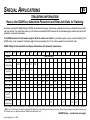
PICKUP BOX REMOVAL PROGRAM
Alterations to Complete Vehicles
Persons who alter complete (certified) Pickup Trucks by removal of the Pickup box should be aware that this type of activity would
impose upon them the corresponding responsibility for ensuring that the units as sold are in compliance with all applicable safety and/or
emissions (including noise and RFI) requirements. Specific questions concerning compliance or certification to these requirements should
be directed to the vehicle alterer’s legal counsel or the National Highway Traffic Safety Administration, the Environmental Protection
Agency, the California Air Resources Board, or in Canada, the Ministry of Transport or the Canadian Department of Commerce.
The Environmental Protection Agency has provided an explanation of the policy they will follow regarding the modification by the
secondary manufacturers of complete Light Duty Trucks prior to sale and delivery to the ultimate purchaser. This explanation is
contained in a letter from C. N. Freed of the EPA to M.M. McBride of the Recreation Vehicle Industry Association, dated July 13, 1979. A
portion of this letter states:
“...Secondary manufacturers are not manufacturers under the act when the following conditions are met:
1. The vehicles produced by a secondary manufacturer conform in all material respects to the design specification in the original
manufacturer’s application for certification (hereafter ‘application’); and
2. The weight of the vehicle produced by a secondary manufacturer, including the weight of fuel at nominal tank capacity, is no
more than 500 lbs. above the maximum vehicle weight.”
No frontal area restrictions will apply to secondary manufacturers who comply with the conditions above. However, every vehicle sold to
an ultimate purchaser must be covered by emission warranty mandated by section 270(a) of the Act. Secondary manufacturers who do
not meet the above conditions will be considered manufacturers under the Act and will be required to ensure that the vehicles they
produce are covered by a certificate of conformity.
The Maximum vehicle weight for a given vehicle is determined by:
A) Subtracting 300 lbs. from the highest loaded vehicle weight (see 40 CFR 86.079-2 for loaded vehicle weight definition and the
table at 40 CFR 86.129-80) associated with the test weight listed in the application for the vehicle, and
B) Adding the weight of all options that are offered by the original manufacturer for the applicable truck line that were not included
in the curb weight reported in the application.
(Alterations – continued on next page)
S/T — GENERAL INFORMATION ONLY / C/K — ALL / DRAWINGS FOR C/K ONLY
Special Applications – 2001
PAGE
SPECIAL APPLICATIONS
38
(Alterations – continued from previous page)
In the case of mutually exclusive options, only the weight of the heavier option is to be used when computing the maximum vehicle weight.
Those who wish to remove the Pickup box from a Pickup Truck for the purpose of installing special equipment or another type of body
should be further advised that a Pickup may require modification in one of the following areas. Before a decision is made to alter a C/K or
S Pickup Model, please be advised of the following considerations:
Vehicle:
Analyze the vehicle specifications for product content. The option content of a particular vehicle will determine which if any of
the four areas of modification might not be applicable to the vehicle alterations contemplated.
Service Parts:
The service parts and related service part number as outlined in the four areas of modification may be ordered through your
local Chevrolet/GMC Dealer. Contact your Dealer’s Service Parts Representative for availability and price.
Areas of Modification:
1. Fuel filler neck assembly, housing, and ground strap.
2. Rear axle vent hose.
3. Tail lamp, tail lamp wiring harness and license plate bracket assembly.
4. Spare tire mounting.
5. Body pressure relief valve (see UI Bulletin #44).
S/T — GENERAL INFORMATION ONLY / C/K — ALL / DRAWINGS FOR C/K ONLY
Special Applications – 2001
PAGE
SPECIAL APPLICATIONS
39
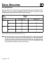
Federal Motor Vehicle Safety Standards
FMVSS 101 – Controls and Displays
A The following statement is applicable to Chassis Cab, Cutaway Van, Suburban, Van, Pickup and Utility with a GVWR of
10,000 lbs. or less (unless otherwise noted on the cover of this document).
This incomplete vehicle, when completed, will conform to FMVSS 101 providing no alterations are made which affect the size,
location, identification or illumination of the controls and displays identified below or the location, travel and type of seat. If the seat
is installed by the final stage manufacturer, the visibility and operation of the controls and displays listed below must meet the
requirements of paragraph S5 of the standard:
Vehicle and system controls and displays including:
Hazard warning signal control and tell-tale
High beam control and indicator
Steering wheel
Service brake
Accelerator
Horn control
Clutch
Ignition control
Gear position display
Headlamp control
Turn signal, control and display
Brake failure warning display
Illumination intensity control
Fuel level display
Windshield wiper control
Windshield washer control
Oil pressure display
Electrical charge display
Manual choke control
Tail lamps/control
Engine coolant temperature display
Rear window defrosting and defogging controls
Manual transmission shift lever, except transfer case
Heating system controls (including fan)
Air conditioning system controls (including fan)
Engine start control
Engine stop control
Hand throttle control
Clearance lamp control
Side marker lamp control
Identification lamp control
Windshield defrosting and defogging controls
Speedometer display
* Odometer (must be metric)
* Trip recorder (must be metric)
* Hub odometer (must be metric)
Automatic vehicle speed control
Seat belt tell-tale
Anti-lock brake failure warning display
Air bag tell-tale (if so equipped)
* For Canada MVSS only, when Canadian option is specified.
S/T — GENERAL INFORMATION ONLY / C/K — ALL / DRAWINGS FOR C/K ONLY
Special Applications – 2001
PAGE
SPECIAL APPLICATIONS
40
FMVSS 102 – Transmission Shift Lever Sequence, Starter Interlock and Transmission Braking Effect
A The following statement is applicable to Chassis Cab, Van, Pickup, Utility and Subruban (unless otherwise noted on the cover
of this document).
This incomplete vehicle, when completed, will conform to FMVSS 102 providing no alterations are made which affect the function,
physical or mechanical properties, environment, location or vital spatial clearances of the components, assemblies or systems
identified below:
1. Transmission control and identification system, including but not limited to:
Automatic transmission assembly (A/T)
A/T control from steering column to transmission linkage
A/T control from floor shift mechanism to
transmission linkage
A/T steering column assembly
A/T floor shift mechanism
A/T neutral safety back-up switch assembly and wire
Vehicle wiring harness
A/T position indicator dial
A/T position indicator pointer
A/T position indicator actuating linkage
Transmission shift position pattern (knob, plate or label)
FMVSS 103 – Windshield Defrosting and Defogging Systems
A The following statement is applicable to Chassis Cab and Cutaway Van (unless otherwise noted on the cover of this document).
This incomplete vehicle, when completed, will conform to FMVSS 103 providing no alterations are made which affect the function,
physical or mechanical properties, environment, location or vital spatial clearances of the components, assemblies or systems
identified below:
Windshield defrosting and defogging systems, including but limited to:
Windshield assembly
Heater and defroster assembly
(including motor and blower)
Heater and water hoses/hose assemblies
Heater blower motor resistor assembly
Defroster air duct assembly
Defroster air hoses (distributor to nozzle)
Defroster outlet to heater assembly adaptor
Chassis and instrument panel wiring harness assembly
Heater and defroster control
(electrical, mechanical, vacuum)
Vacuum control hoses
Defroster air distributor assembly (manifold)
Defroster air to windshield outlet assembly (nozzle)
(it affects high blower speed)
Engine water outlet thermostat assembly
Heater and air conditioning wiring harness
Engine wiring harness
S/T — GENERAL INFORMATION ONLY / C/K — ALL / DRAWINGS FOR C/K ONLY
Special Applications – 2001
PAGE
SPECIAL APPLICATIONS
41
FMVSS 104 – Windshield Wiping and Washing Systems
A The following statement is applicable to Chassis Cab, Cutaway Van, Pickup, Utility, Van and Suburban (unless otherwise
noted on the cover of this document).
This incomplete vehicle, when completed, will conform to FMVSS 104 providing no alterations are made which affect the function,
physical or mechanical properties, environment, location or vital spatial clearances of the components, assemblies or systems identified below:
Windshield wiping and washing systems, including but limited to:
Windshield assembly
Windshield wiper arm assembly
Windshield wiper blade assembly
Windshield wiper linkage assembly
Windshield wiper/washer control
Windshield wiper/washer motor/pump assembly
Windshield module attachments
Windshield washer fluid reservoir
Washer reservoir cap
Water reservoir filler assembly
Windshield washing system hoses
Windshield washer nozzle
Vehicle wiring harness
FMVSS 105 – Hydraulic Service Brake, Emergency and Parking Brake Services
Allowable center of gravity variation (C/K, G Van, M/L Van).
These charts detail the envelope of allowable center of gravity variation for completed vehicles. This is significant for the lightly loaded
portion of FMVSS 105, which is defined as curb plus 400 pounds distributed in the driver-passenger area of the vehicle.
The lightly loaded center of gravity of complete vehicles needs to be restricted so it will meet FMVSS 105 stopping distances. The laden
center of gravity does not need to be specified as it is controlled within the FMVSS 105 test procedure by specific instructions as to how
ballast is to be placed (while height is not controlled, it is assumed that for test purposes it would be reasonable).
S/T — GENERAL INFORMATION ONLY / C/K — ALL / DRAWINGS FOR C/K ONLY
Special Applications – 2001
PAGE
SPECIAL APPLICATIONS
42
Allowable Center of Gravity Calculation
C.G. of vehicle in FMVSS unladen condition (Curb + 400 lbs.) must be inside shaded area – that is, it must be within the trapezoid
formed by the coordinates A, B, C, D, H1, & H2, plus it must be to the rear of vertical line E and forward of vertical line F.
d
=
h
=
d
h
Wrc
Wrb
W.B.
Wt
=
=
=
=
=
=
h1
=
Wc
h2
Wb
150
10,000
=
=
=
=
=
(Wrc + Wrb + 150) W.B.
Wt
(h1Wc + h2Wb + 10,000)
Wt
horizontal distance from front wheels to completed vehicle center of gravity (inches)
vertical distance from ground to completed vehicle center of gravity (inches)
rear component of bare chassis weight (pounds)
rear component of body weight (pounds)
vehicle wheelbase (inches)
total weight of chassis, body (pounds) plus 400 pounds
center of gravity height from ground of the bare chassis, selected from the
following value by model: C/K = 28”, G = 32”, M/L = 28”, P30 = 24”
total weight of bare chassis (pounds)
center of gravity height of body from ground (inches)
total weight of body (pounds)
rear component of 400 pounds (from lightly loaded definition)
400 pounds (from lightly loaded definition) multiplied by its vertical center of gravity height (assumed) of 25 inches
NOTE: An alternate method of center of gravity calculation may be found in the current issue of the General Motors Body
Builders Book in the general instruction section and in SVIE Bulletin #39.
S/T — GENERAL INFORMATION ONLY / C/K — ALL / DRAWINGS FOR C/K ONLY
Special Applications – 2001
PAGE
SPECIAL APPLICATIONS
43
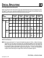
2001 Allowable Center of Gravity Charts
Incomplete, Pickup Box Removal, or Snowplow Prep Package Vehicles
Coordinates of Allowable C/G Variation at
Forward Rearward
FMVSS Unladen (Curb Wt. + 400 lbs.)
C/G Limit C/G Limit
Model
GVWR
C25906
K25906
S10803
C15903
C15753
C15953
K15903
K15753
K15953
C15743
K15743
C25903
C25903
C25753
C25743
C25953
C25943
K25753
K25903
8600
8600
4900
6400
6200
6400
6400
6400
6400
8600
8600
8600
9200
9200
9200
9200
9200
8600
9200
SRW
DRW
C/G
Brake
System
JH6
JH6
JM3
JC5
JC5
JC5
JC5
JC5
JC5
JH6
JH6
JH6
JH6
JH6
JH6
JH6
JH6
JH6
JH6
= Single Rear Wheel
= Dual Rear Wheel
= Center of Gravity
Wheel
base
130.0
130.0
N/A
133.0
143.5
157.5
133.0
143.5
157.5
153.0
153.0
133.0
133.0
143.5
153.0
157.5
167.0
143.5
133.0
SRW
DRW
SRW
SRW
N/A
SRW
SRW
SRW
SRW
SRW
SRW
SRW
SRW
SRW
SRW
SRW
SRW
SRW
SRW
SRW
SRW
H1
H2
A
B
C
D
E
F
12
12
13.4
12
12
12
12
12
12
12
12
12
12
12
12
12
12
12
12
48
48
36.6
48
48
48
48
48
48
48
48
48
48
48
48
48
48
48
48
36
36
37
34
37
42
34
37
42
51
51
36
45
48
51
52
55
39
45
63
63
45.8
59
64
68
59
64
68
77
77
59
71
74
77
78
80
64
71
70
70
88
70
76
79
70
76
79
61
61
70
54
58
61
63
66
76
54
97
97
95
95
102
105
95
102
105
88
88
93
81
84
88
89
93
100
81
43
43
N/A
44
48
52
44
48
52
51
51
44
45
48
51
52
55
47
45
97
97
N/A
95
102
105
95
102
105
88
88
93
81
84
88
89
93
100
81
Brake Systems:
Vacuum Powered Boosters
Hydraulic Powered Boosters
JC5
JH5, JH6, and JH7
S/T — GENERAL INFORMATION ONLY / C/K — ALL / DRAWINGS FOR C/K ONLY
Special Applications – 2001
PAGE
SPECIAL APPLICATIONS
44
2001 Allowable Center of Gravity Charts (continued)
Incomplete, Pickup Box Removal, or Snowplow Prep Package Vehicles
Coordinates of Allowable C/G Variation at
Forward Rearward
FMVSS Unladen (Curb Wt. + 400 lbs.)
C/G Limit C/G Limit
Model
GVWR
K25753
K25743
K25953
K25943
C35903
C35953
C35943
K35903
K35953
K35943
C36003
C36053
C36403
C36453
K36003
K36053
K36403
K36453
9200
9200
9200
9200
11,400
11,400
11,400
11,400
11,400
11,400
11,400
11,400
11,400
11,400
12,000
12,000
12,000
12,000
SRW
DRW
C/G
Brake
System
JH6
JH6
JH6
JH6
JH7
JH7
JH7
JH7
JH7
JH7
JH7
JH7
JH7
JH7
JH7
JH7
JH7
JH7
= Single Rear Wheel
= Dual Rear Wheel
= Center of Gravity
Wheel
base
143.5
153.0
157.5
167.0
133.0
157.5
167.0
133.0
157.5
167.0
137.0
161.5
161.5
185.5
137.0
161.5
161.5
185.5
SRW
DRW
SRW
SRW
SRW
SRW
DRW
DRW
DRW
DRW
DRW
DRW
DRW
DRW
DRW
DRW
DRW
DRW
DRW
DRW
H1
H2
A
B
C
D
E
F
12
12
12
12
12
12
12
12
12
12
12
12
12
12
12
12
12
12
48
48
48
48
48
48
48
48
48
48
48
48
48
48
48
48
48
48
48
51
52
55
41
48
50
41
48
50
43
49
49
55
43
49
49
55
74
77
78
80
59
65
68
59
65
68
60
67
67
73
60
67
67
73
58
61
63
66
99
116
123
99
116
123
102
119
119
136
102
119
119
136
84
88
89
93
109
128
135
109
128
135
112
131
131
148
112
131
131
148
48
51
52
55
41
48
50
41
48
50
43
49
49
55
43
49
49
55
84
88
89
93
109
128
148
109
128
148
112
131
131
148
112
131
131
148
Brake Systems:
Vacuum Powered Boosters
Hydraulic Powered Boosters
JC5
JH5, JH6, and JH7
S/T — GENERAL INFORMATION ONLY / C/K — ALL / DRAWINGS FOR C/K ONLY
Special Applications – 2001
PAGE
SPECIAL APPLICATIONS
45
FMVSS 106 – Brake Hoses
A The following statement is applicable to all types of incomplete vehicles (unless otherwise noted on the cover of this document).
This incomplete vehicle, when completed, will conform to FMVSS 106 providing no alterations are made which affect the function,
physical or mechanical properties, environment, location or vital spatial clearances of the components, assemblies or systems
identified below:
Hoses and hose end fittings
Labeling requirements
FMVSS 108 – Lamps, Reflective Devices and Associated Equipment
A The following statement is applicable to Chassis Cab (unless otherwise noted on the cover of this document).
This incomplete vehicle, when completed, will conform to FMVSS 108 if it is completed with a body over 80 inches wide providing the
following conditions are met:
1. Each of these devices must be properly installed on the completed vehicle and meet all the requirements of FMVSS 108:
a. The following devices when provided, located and/or wired by General Motors meet the requirements of this standard:
Headlamps and/or foglamps
Front side marker reflex reflectors
Front side marker lamps
Front turn signal lamps
Turn signal operating unit
Turn signal flasher
Vehicle hazard warning signal operating unit
Vehicle hazard warning signal flasher
Mud flaps w/reflectors (Tractor only)
Front cab roof clearance and identification lamps
Rear reflex reflectors
Tail lamps
Stop lamps
License plate lamp
Rear turn signal lamps
Back-up lamps
Center high-mounted stop lamp
Rear cab conspicuity reflectors (Tractor only)
b. No part of the completed vehicle shall be installed so as to prevent any of the devices listed in (a) above from meeting their
required photometric output at the specified test points. If such interference exists, the applicable devices may have to be
relocated or additional devices added to meet the requirements of FMVSS 108. Any FMVSS 108 part shall not be painted.
c. The following additional devices must be installed on the van body and meet all the requirements of this standard:
Rear side marker lamps
Front and rear clearance lamps
Rear side marker reflex reflectors
Front and rear identification lamps
(FMVSS 108 — continued on next page)
S/T — GENERAL INFORMATION ONLY / C/K — ALL / DRAWINGS FOR C/K ONLY
Special Applications – 2001
PAGE
SPECIAL APPLICATIONS
46
(FMVSS 108 — continued from previous page)
d. The following additional devices must be installed on the van body and meet all the requirements of this standard if the overall
vehicle length is 30 feet or greater:
Intermediate side marker lamps
Intermediate side reflex reflectors
e. C/K 300(03) and Medium Duty C6, C7, F7 Chassis Cabs with Roof Marker Lamp – Delete, Option 9H5 will comply with
Standard 108 provided clearance and identification marker lamps are installed on the completed vehicle.
2. No alterations (other than any relocation of items in 1(a) which may be necessary to conform to the standard) should be made
which affect the location, mounting surfaces, function, environment or visibility clearance of the above listed devices which have
been installed on this incomplete vehicle.
# Body Builders or Dealers, after removing wooden shipping bumper, must relocate rear tail, stop and turn lights by switching the left
hand and right hand brackets and lamp assembly so that the lights are mounted outboard of the shipping position. Two additional
installation bolts are included in the Incomplete Vehicle Document Envelope.
FMVSS 111 – Rearview Mirrors
B The following statement is applicable to a 1500/2500/3500 Series Chassis Cab (unless otherwise noted on the cover of this
document).
This incomplete vehicle, when completed, will conform to FMVSS 111 providing there is conformity to the following appropriate
requirements: (1) the driver’s seat location is not altered and a body, of not more than 80 inches in overall width, is installed
symmetrically about the vehicle centerline; (2) when outside rearview mirror option DF2, DG5, 8B2, 8G9, 9F7 or 9F8 is ordered and the
driver’s seat location is not altered and a body, of not more than 96 inches in overall width, is installed symmetrically about the vehicle
centerline; (3) when the seat is installed by the final stage manufacturer (w/8E2) in a different location than a production vehicle, the
vehicle will conform to the requirements of paragraph S6 or S7 of FMVSS 111 when outside rearview mirror option DF2, DG5, 8B2,
8G9, 9F7 or 9F8 is ordered and a body, of not more than 96 inches overall width, is installed symmetrically about the vehicle centerline.
E The following statement is applicable to M/L05/06 Van, Suburban, G05, 06 Vans, ST Pickup and Blazer/Yukon (unless
otherwise noted on the cover of this document).
This vehicle will conform to FMVSS 111 providing no alterations or substitutions are made to the outside or inside mirrors furnished
with the vehicle, the driver’s seat location is not altered and the body width is not increased.
S/T — GENERAL INFORMATION ONLY / C/K — ALL / DRAWINGS FOR C/K ONLY
Special Applications – 2001
PAGE
SPECIAL APPLICATIONS
47
FMVSS 112 – Headlamp Concealment Devices
A The following statement is applicable to all four basic types of incomplete vehicles (unless otherwise noted on the cover of
this document).
Conformity with FMVSS 112 is not substantially affected by the design of this incomplete vehicle and General Motors makes no
representation as to the conformity with this standard.
FMVSS 113 – Hood Latch System
A The following statement is applicable to Chassis Cab, Van, Cutaway Van, Utility and Suburban (unless otherwise noted on the
cover of this document).
This incomplete vehicle, when completed, will conform to FMVSS 113 providing no alterations are made which affect the function,
physical or mechanical properties, environment, location or vital spatial clearances of the components, assemblies or systems
identified below:
Hood latch systems, which may include but are not limited to:
Hood latch (catch) assembly
Hood latch support assembly
Hood latch pilot
Hood latch striker plate (hook)
FMVSS 114 – Theft Protection (GVWR of 10,000 Pounds or Less)
A The following statement is applicable to Chassis Cab, Bare Chassis, Van and Cutaway Van (unless otherwise noted on the
cover of this document).
This incomplete vehicle, when completed, will conform to FMVSS 114 providing no alterations are made which affect the function,
physical or mechanical properties, environment, location or vital spatial clearances of the components, assemblies or systems
identified below:
Steering column lock assembly
S/T — GENERAL INFORMATION ONLY / C/K — ALL / DRAWINGS FOR C/K ONLY
Special Applications – 2001
PAGE
SPECIAL APPLICATIONS
48
U.S. CFR 49, PART 565/CMVSS 115 – Vehicle Identification Number
A The following statement is applicable to all incomplete vehicles (unless otherwise noted on the cover of this document).
This incomplete vehicle, when completed, will conform to CMVSS 115 and U.S. CFR 49, part 567, providing no alterations are made
to the Vehicle Identification Number or to the environment, location, vital spatial clearances or visibility of the VIN Plate.
FMVSS 116 – Motor Vehicle Brake Fluids
A The following statement is applicable to all three basic types of incomplete vehicles (unless otherwise noted on the cover of
this document).
This incomplete vehicle, when equipped with approved hydraulic brake fluid will conform to FMVSS 116 providing no alterations are
made which affect the physical or chemical properties of the brake fluid.
FMVSS 120 – Tire Selection and Rims for Vehicles Other than Passenger Cars
A The following statement is applicable to all three basic types of incomplete vehicles (unless otherwise noted on the cover of
this document).
This incomplete vehicle, when completed, will conform to FMVSS 120 providing no alterations are made which affect the function,
physical or mechanical properties or the attachment of the wheels and tires.
The tire and wheel information shown on the Incomplete Vehicle Document Label must be transferred to the final stage manufacturer’s
Certification label or Tire Information Label providing no equipment changes are made.
S/T — GENERAL INFORMATION ONLY / C/K — ALL / DRAWINGS FOR C/K ONLY
Special Applications – 2001
PAGE
SPECIAL APPLICATIONS
49
FMVSS 124 – Accelerator Control Systems
A The following statement is applicable to Chassis Cab, Van and Cutaway Van (unless otherwise noted on the cover of this
document).
This incomplete vehicle, when completed, will conform to FMVSS 124 providing no alterations are made which affect the function,
physical or mechanical properties, environment, location or vital spatial clearances of the components, assemblies or systems
identified below:
Accelerator control systems, including but not limited to:
Lever, throttle or accelerator and supporting bracket
Cable or rod, throttle or accelerator and support bracket including seals
Electronic throttle control assembly and related wiring
Cruise control module, wiring and cable (if so equipped)
Spring(s)-throttle or accelerator return
Pedal-throttle or accelerator and attachments
Floor covering material must not be installed under pedal nor within 1 inch of side of pedal
Attachment pin, hole or ball stud to carburetor/port fuel injection unit throttle lever
FMVSS 201 – Occupant Protection in Interior Impacts (GVWR of 10,000 Pounds or Less)
A The following statement is applicable to Chassis Cab and Cutaway Van (unless otherwise noted on the cover of this document).
This incomplete vehicle, when completed, will conform to FMVSS 201 providing no alterations are made which affect the function,
physical or mechanical properties, environment, location or vital spatial clearances of the components, assemblies or systems
identified below:
Instrument panel
Seats
Interior compartment doors
Sunvisors
Arm rests
Headliner
Upper interior trim
S/T — GENERAL INFORMATION ONLY / C/K — ALL / DRAWINGS FOR C/K ONLY
Special Applications – 2001
PAGE
SPECIAL APPLICATIONS
50
FMVSS 202 – Head Restraints (GVWR of 10,000 Pounds or Less)
A The following statement is applicable to Chassis Cab, Cutaway Van, Van, Suburban, Pickup and Blazer/Yukon (unless
otherwise noted on the cover of this document).
This incomplete vehicle, when completed, will conform to FMVSS 202 providing no alterations or substitutions are made to the seat
assemblies.
FMVSS 203 – Impact Protection for the Driver from the Steering Control System (GVWR of 10,000 Pounds or Less)
A The following statement is applicable to Chassis Cab and Cutaway Van (unless otherwise noted on the cover of this document).
This incomplete vehicle, when completed, will conform to FMVSS 203 providing no alterations are made which affect the function,
physical or mechanical properties, elements, location or vital spatial clearances of the components, assemblies or systems identified
below:
Instrument Panel
Driver seat assembly
Steering column assembly, including steering wheel
FMVSS 204 – Steering Control Rearward Displacement (GVWR of 10,000 Pounds or Less)
A The following statement is applicable to Chassis Cab, Van, Suburban and Utility (unless otherwise noted on the cover of this
document).
This incomplete vehicle, when completed, will conform to FMVSS 204 providing no alterations are made to the cab and front end
sheet metal and structural components, roof, hood, hood mechanism, doors, fenders, pillars, fender reinforcement, cowl, bumpers
and bumper mounting system, frame/frame reinforcement, front suspension and front crossmember or steering control system or
other components that would affect the steering control system displacement in a 30 m.p.h. fixed barrier impact.
FMVSS 205 – Glazing Materials
A The following statement is applicable to Chassis Cab, Van, Cutaway Van, Pickup and Utility (unless otherwise noted on the
cover of this document).
This incomplete vehicle, when completed, will conform to FMVSS 205 providing no alterations are made which affect the physical or
chemical properties of the glazing material or the monogram or the visibility of the monogram.
S/T — GENERAL INFORMATION ONLY / C/K — ALL / DRAWINGS FOR C/K ONLY
Special Applications – 2001
PAGE
SPECIAL APPLICATIONS
51
FMVSS 206 – Door Locks and Door Retention Components (Not Applicable to Bus)
A The following statement is applicable to Cutaway Van, Van and Chassis Cab (unless otherwise noted on the cover of this
document).
This incomplete vehicle, when completed, will conform to FMVSS 206 providing no alterations are made which affect the function,
physical or mechanical properties, environment, location or vital spatial clearances of the components, assemblies or systems
identified below:
Door and pillar systems, including but not limited to:
Door lock
Inside lock control linkage
Door latch
Door wedges
Door latch striker plate
Door hinge
Exterior door handles
FMVSS 207 – Seating Systems
A The following statement is applicable to Chassis Cab and Cutaway Van (unless otherwise noted on the cover of this document).
This incomplete vehicle, when completed, will conform to FMVSS 207 providing no alterations are made which affect the function,
physical or mechanical properties, environment, location and vital spatial clearances of the components, assemblies or systems
provided and identified below:
Seating systems, including but not limited to:
Seat assembly
Folding seat or seat back latch assembly
Seat or seat back latch striker
Seat riser
Seat adjuster assembly
Seat or seat back latch assembly
Seat or seat back latch release control
Seat anchorages brackets, reinforcements, attachment hardware, etc.
If the intermediate or final stage manufacturer installs any additional seats, they will also have to meet the requirements of this standard.
S/T — GENERAL INFORMATION ONLY / C/K — ALL / DRAWINGS FOR C/K ONLY
Special Applications – 2001
PAGE
SPECIAL APPLICATIONS
52
FMVSS 208 – Occupant Crash Protection
A The following statement is applicable to the vehicles having an unloaded vehicle weight of more than 5500 pounds or a GVWR
greater than 8500 pounds.
This incomplete vehicle, when completed, will conform to FMVSS 208 providing no alterations are made to the number, location or
configuration of the designated seats/seating positions or to the number, placement, installation or model number of the seat belt
assemblies of this incomplete vehicle.
B The following statement is applicable to vehicles having an unloaded vehicle weight of 5500 pounds or less and a GVWR of
8500 pounds or less but without AQ8, VK5, YF7, 8E2, and to G31706 Vans with seating arrangement RPO ZX2.
This incomplete vehicle, when completed, will conform to FMVSS 208 providing it is completed in accordance with the following
specific conditions by the final stage manufacturer:
1. The front seat belts provided by General Motors will conform to the requirements of FMVSS 208, providing no alterations are
made to:
a. the number, location or configuration of the designated seating positions; and
b. the number, placement, installation or model number of the seat belt assemblies provided; and
c. the instrument panel or its mounting, the steering column/shaft or its mounting, the knee bolster or its mounting, the steering
wheel, horn pad, driver air bag module or its mounting and covering, passenger air bag module or its mounting or covering
(if so equipped), air bag crash sensors, Sensor Diagnostic Module (SDM) in C/K, M/L and G Vans, and all air bag system
wiring. Do not relocate or move the SDM.
Do not obstruct the path of air bag deployment. (See restricted area reference in appendix.)
Do not mount any components that produce more than a 20 Gauss magnetic field as measured at the SDM. Speakers/
magnets must be located at least 5 inches from the SDM.
You must disconnect the SDM before doing any welding on the vehicle, otherwise do not disconnect the SDM.
(FMVSS 208 — continued on next page)
S/T — GENERAL INFORMATION ONLY / C/K — ALL / DRAWINGS FOR C/K ONLY
Special Applications – 2001
PAGE
SPECIAL APPLICATIONS
53
(FMVSS 208 — continued from previous page)
If the sunshade is removed or altered, a new Inflatable Restraints System Caution label must be installed per the sketch
found in Part III of this document. A label has been shipped loose. In order to be in compliance with FMVSS 208 no other
label shall be installed on the same side of the sunvisor as the Inflatable Restraint Caution (Air Bag ) label. Instrument panel
temporary warning label must not be removed.
NOTE: All air bag components have yellow connectors.
CAUTION: To help avoid Personal Injury Due to unwanted air bag inflation, observe the following precautions!
Do not weld, solder, braze, hammer, machine, drill, heat, electrical splice, add onto, remove, relocate, test, paint, loosen or in
any way alter air bag components or wiring or fuses. Carpet may be put over the SDM if an appropriate moisture barrier (such
as a rubber matted backing) is supplied.
When performing any operation around air bag components or wiring including but not limited to any operations around the
instrument panel, electrical wiring and fuse block, steering column/wheel, and the engine compartment you must disable the
air bag system prior to the operation. If the vehicle is equipped with an SDM, you must disable the air bag system prior to
upfitting. Note: Striking or dropping a powered SDM may cause air bag deployment. The air bag system must be enabled after
operation completion. This must be verified before shipping the vehicle. Instructions for disabling and enabling the air bag
system can be found in the GM service manual for the specific product line.
d. the vehicle frame, front bumper system, front sheet metal or other front structure, roof structure, doors, floor pan, driveline or
contents of the engine compartment by any subsequent manufacturer which would result in any difference from the modified
vehicle’s deceleration if the modified vehicle were to be subjected to barrier impact tests conducted per FMVSS 208.
2. The rear seat belts provided by General Motors will conform to FMVSS 208 providing no alterations are made to the number,
location or configuration of the designated seats/seating positions or to the number, placement, installation or model number of
the seat belt assemblies of this incomplete vehicle.
S/T — GENERAL INFORMATION ONLY / C/K — ALL / DRAWINGS FOR C/K ONLY
Special Applications – 2001
PAGE
SPECIAL APPLICATIONS
54
FMVSS 209 – Seat Belt Assemblies
A The following statement is applicable to Chassis Cab, G or M/L05 Vans (unless otherwise noted on the cover of this
document).
This incomplete vehicle, when completed, will conform to FMVSS 209 providing no alterations or substitutions are made to the seat
belt assemblies, attachment hardware, Owner’s Manual Instructions or seats provided. For vehicles having GVWR of 8500 pounds or
less, the vehicle model number as shown on the label on the cover of this document must be included on the final stage manufacturer’s
certification label.
FMVSS 210 – Seat Belt Assembly Anchorages
A The following statement is applicable to Chassis Cab, G05 or M/L05 Vans (unless otherwise noted on the cover of this
document).
This incomplete vehicle, when completed, will conform to FMVSS 210 providing no additional occupant seats or seat belt assembly
anchorages are added and no alterations are made which affect the function, physical or mechanical properties, environment,
location or vital spatial clearances of the components, assemblies or systems identified below:
Seat belt systems, including but not limited to:
Seat assemblies
Floor pan assembly
Seat belt routing
Seat belt assemblies
Seat position/adjustment capability
Seat belt anchorage brackets/reinforcements
Child restraining Anchorage
S/T — GENERAL INFORMATION ONLY / C/K — ALL / DRAWINGS FOR C/K ONLY
Special Applications – 2001
PAGE
SPECIAL APPLICATIONS
55
FMVSS 212 – Windshield Mounting (GVWR of 10,000 Pounds or Less)
A This Chassis Cab or Van, when completed, will conform to FMVSS 212 if:
1. No alterations are made to the cab and front end structural components including roof, hood and hood mechanism, doors,
fenders, pillars, fender reinforcement, cowl, bumpers and bumper mounting system, windshield and windshield mounting system
and frame/frame reinforcement.
2. The maximum weight of the body and/or equipment installed must be such that the completed vehicle’s unloaded vehicle weight
does not exceed the values specified in Table “A”, as applicable.
3. The center of gravity for the respective body type of the installed body and accessories does not exceed the maximum center of
gravity height specified in Table “A”.
4. The height above the frame of the body or accessories does not exceed the maximum body height specified in Table “A”.
5. The clearance between the rear most part of the cab and the front of the body is not less than the minimum cab to body clearance
specified in Table “A”.
6. The minimum vertical clearance between the cab roof and any portion of the installed body or accessories that extends over the
cab roof must not be less than eight inches.
7. The maximum body weight does not exceed the value specified in Table “A”.
8. During a 30 m.p.h. frontal barrier impact test, no component installed by any subsequent manufacturer shall move forward from its
permanently mounted position.
S/T — GENERAL INFORMATION ONLY / C/K — ALL / DRAWINGS FOR C/K ONLY
Special Applications – 2001
PAGE
SPECIAL APPLICATIONS
56
FMVSS 214 – Side Impact Protection (GVWR of 10,000 Pounds or Less – Static) (GVWR of 6,000 Pounds or Less – Dynamic)
A The following statement is applicable to Chassis Cab, Van, Suburban, Pickup and Utility (unless otherwise noted on the cover
of this document).
This incomplete vehicle, when completed, will conform to FMVSS 214 providing no alterations are made to the cab, roof, floor, side
pillars, fuel system, chassis, structural components and door assemblies.
FMVSS 216 – Roof Crush Resistance (GVWR of 6,000 Pounds or Less)
A The following statement is applicable to M/L Vans, Pickups and Utility with a GVWR of 6000 pounds or less (unless otherwise
noted on the cover of this document).
This incomplete vehicle conforms to FMVSS 216 providing no alterations are made to the cab, roof, side pillar, structural components
and door assemblies.
FMVSS 219 – Windshield Zone Intrusion (GVWR of 10,000 Pounds or Less)
A The following statement is applicable to Chassis Cab (unless otherwise noted on the cover of this document).
This incomplete vehicle, when completed, will conform to FMVSS 219 providing: no alterations are made to the cab and front end
structural components, the hood and hood mounts; the vehicle does not exceed the Chassis Cab unloaded vehicle weight specified
in Table “A”; and during a 30 m.p.h. frontal barrier impact test: (1) no component installed by any manufacturer shall prevent the hood
from folding upward along the lateral centerline; and (2) no component installed by any manufacturer shall penetrate the windshield or
protected zone.
Not applicable to walk-in vans, motor homes, tow trucks, ambulance, and other emergency/rescue/medical vehicles to those equipped
for wheelchairs.
S/T — GENERAL INFORMATION ONLY / C/K — ALL / DRAWINGS FOR C/K ONLY
Special Applications – 2001
PAGE
SPECIAL APPLICATIONS
57
FMVSS 301 – Fuel System Integrity MPV’S, Trucks and Buses (GVWR of 10,000 Pounds or Less)
A The following statement is applicable to Chassis Cab and Van (unless otherwise noted on the cover of this document).
This incomplete vehicle, when completed, will conform to FMVSS 301 providing it is completed in accordance with the following
specific conditions by the final stage manufacturer:
1. The following items when installed by General Motors will conform providing no alterations are made which affect the function,
physical or mechanical properties, environment, location or vital spatial clearances of the components, assemblies or systems
identified below:
Fuel feed pipes – front, rear and intermediate
Fuel return pipes – front and rear
Fuel feed and return hose – front rear and intermediate
Fuel tank assembly
Fuel vapor lines and cannister
Fuel tank meter assembly
Fuel tank shields/cage
Fuel tank filler neck plate
Fuel tank cap assembly
Fuel tank filler neck screws
Fuel tank filler neck hose
Fuel tank filler neck vent hose
Fuel tank filler neck vent hose clamp/strap
Fuel tank filler neck hose clamp/clamp assembly
Fuel tank filler neck assembly upper
Fuel filter
Fuel hose shield
2. This incomplete vehicle, when completed, will conform to FMVSS 301 Fuel System Integrity if:
a. No alterations are made to the fuel system and attaching or protective structure.
b. The unloaded cab chassis vehicle weight of the completed vehicle does not exceed the weight listed in Table “A” as applicable.
c. Any subsequent manufacturer completes the fuel filler neck installation according to the instructions available in the current
year’s Body Builders’ Book.
d. During all barrier impact tests:
i. No component installed by any subsequent manufacturer impinges or causes distortion to the fuel system with
sufficient energy to puncture or separate the fuel system.
ii. No vehicle modification by any subsequent manufacturer results in any portion of the vehicle impinging upon or causing
distortion to the fuel system with sufficient energy to puncture or separate the fuel system. Care should be taken that the
structural integrity of the vehicle is restored following any modification of the structure.
S/T — GENERAL INFORMATION ONLY / C/K — ALL / DRAWINGS FOR C/K ONLY
Special Applications – 2001
PAGE
SPECIAL APPLICATIONS
58
2001 S/T and C/K Pickup Box Removal Program – TABLE A
Model
S10803*
4,900 LB GVWR / 117.9” WB
47.1” CA / Regular Cab
CC15743
8,600 LB GVWR / 153.0” WB
42.0” CA / Crew Cab
CK15743
8,600 LB GVWR / 153.0” WB
42.0” CA / Crew Cab
CC15903
6,400 LB GVWR / 133.0” WB
55.9” CA / Regular Cab
CK15903
6,400 LB GVWR / 133.0” WB
55.9” CA / Regular Cab
CC25903
8,600 LB GVWR / 133.0” WB
55.9” CA / Regular Cab
CK25753
8,600 LB GVWR / 143.5” WB
42.0” CA / Extended Cab
* U.S. Only
General
Body
Type
Maximum Body
Center of Gravity
Height (inches)
Maximum
Body Height
(inches)
Minimum Cab to
Body Clearance
(inches)
Maximum Unloaded
Vehicle Weight with
Service Body (lbs)
Maximum
Body Weight
(lbs)
Low Service
9.6 above the frame
Under 22.0
3
3,725
710
Low Service
14.0 above the frame
Under 62.0
3
7,272
1,700
Low Service
14.0 above the frame
Under 62.0
3
6,976
1,700
Low Service
14.0 above the frame
Under 62.0
3
5,034
1,100
Low Service
14.0 above the frame
Under 62.0
3
5,246
1,100
Low Service
High Service
14.0 above the frame
20.3 above the frame
Under 62.0
62.0 & over
3
7,272
1,700
2,600
Low Service
14.0 above the frame
Under 62.0
3
6,689
1,700
Weight of pickup box: 360 lbs. (260 lbs. ST) / Weight of rear bumper: 53 lbs. (35 lbs. ST)
Maximum Body Weight = Maximum Unloaded Vehicle Weight – Curb Weight without Pickup Box and Bumper
Note: Vehicle curb weight can be obtained from label inside driver’s door.
S/T — GENERAL INFORMATION ONLY / C/K — ALL / DRAWINGS FOR C/K ONLY
Special Applications – 2001
PAGE
SPECIAL APPLICATIONS
59
2001 S/T and C/K Pickup Box Removal Program – TABLE A (Continued)
Model
CC25903
9,200 LB GVWR / 133.0” WB
55.9” CA / Regular Cab
CK25903
9,200 LB GVWR / 133.0” WB
55.9” CA / Regular Cab
CC25943
9,200 LB GVWR / 167.0” WB
55.9” CA / Crew Cab
CK25943
9,200 LB GVWR / 167.0” WB
55.9” CA / Crew Cab
CC25953
9,200 LB GVWR / 157.5” WB
55.9” CA / Extended Cab
CK25953
9,200 LB GVWR / 157.5” WB
55.9” CA / Extended Cab
General
Body
Type
Maximum Body
Center of Gravity
Height (inches)
Maximum
Body Height
(inches)
Minimum Cab to
Body Clearance
(inches)
Maximum Unloaded
Vehicle Weight with
Service Body (lbs)
Maximum
Body Weight
(lbs)
Low Service
High Service
14.0 above the frame
20.3 above the frame
Under 62.0
62.0 & over
3
7,272
1,700
2,600
Low Service
14.0 above the frame
Under 62.0
3
6,730
1,700
Low Service
High Service
14.0 above the frame
20.3 above the frame
Under 62.0
62.0 & over
3
8,520
1,700
2,600
Low Service
14.0 above the frame
Under 62.0
3
8,520
1,700
Low Service
High Service
14.0 above the frame
20.3 above the frame
Under 62.0
62.0 & over
3
8,254
1,700
2,600
Low Service
14.0 above the frame
Under 62.0
3
7,750
1,700
Weight of pickup box: 360 lbs. (260 lbs. ST) / Weight of rear bumper: 53 lbs. (35 lbs. ST)
Maximum Body Weight = Maximum Unloaded Vehicle Weight – Curb Weight without Pickup Box and Bumper
Note: Vehicle curb weight can be obtained from label inside driver’s door.
S/T — GENERAL INFORMATION ONLY / C/K — ALL / DRAWINGS FOR C/K ONLY
Special Applications – 2001
PAGE
SPECIAL APPLICATIONS
60
FMVSS 302 – Flammability of Interior Materials
A The following statement is applicable to Chassis Cab, Van, Suburban, Pickup and Utility (unless otherwise noted on the cover
of this document).
This incomplete vehicle, when completed, will conform to FMVSS 302 providing no alterations or substitutions are made which affect
any materials, parts or components identified below and installed on the vehicle by General Motors:
Seat cushions
Sunvisors
Seat backs
Curtains
Seat belts
Shades
Headlining
Wheel housing covers
Arm rests
Head restraints
Floor covering
Engine compartment covers
Console
Instrument panel
Compartment shelves
All trim panels including door, front, rear and side panels
Any other interior materials, including padding and crash deployed elements that are designed to
absorb energy on contact by occupants in the event of a crash
Canada Motor Vehicle Safety Standards
CMVSS
NO.
TITLE
CHASSIS
CAB
CUTAWAY
VAN
1101
1102
1103
1104
1105
1106
108
Emission device......................................................................................................
Crankcase emission ...............................................................................................
Exhaust emission ...................................................................................................
Opacity (Diesel engine only) ...................................................................................
Evaporate emissions (Vehicles 6,000 lbs. GVW or less).........................................
Noise ......................................................................................................................
Lighting equipment (Daytime running lamps) .........................................................
A
A
A
A
A
A
A
A
A
A
A
A
A
A
—
A
CANADA RADIO INTERFERENCE REGULATION
Radio Noise ............................................................................................................
A
S/T — GENERAL INFORMATION ONLY / C/K — ALL / DRAWINGS FOR C/K ONLY
Special Applications – 2001
PAGE
SPECIAL APPLICATIONS
61
STATEMENTS REGARDING CANADA MOTOR VEHICLE SAFETY STANDARDS
C The following statement is applicable to all three basic types of incomplete vehicles (unless otherwise noted on the cover of
this document).
This incomplete vehicle, when completed, will conform to the above standards except CMVSS 1106 providing no alterations
are made which affect the function, physical or mechanical properties, environment, locations or vital spatial clearances of the
components identified below:
*
*
*
*
*
*
*
Engine assembly
Carburetor/T.B.I. and choke controls
Ignition system
A.I.R. system
Exhaust emission control system
P.C.V. system
Intake system
Exhaust system
Catalytic converter
*
*
*
*
*
*
Fuel system
Evaporative emission control system
Transmission assembly
Axle
Tires
Fan and drive
Diesel fuel injection controls
Turbocharger and associated controls
Noise shields/insulation
Conformity with CMVSS 1106 is not determined solely by the design of this incomplete vehicle. Providing no alterations are made to
the noise attenuation components identified thus * in the above list, the capability exists to certify the vehicle with the chassis
components provided by General Motors.
CMVSS 108 – Lighting Equipment (Daytime Running Lamps)
A The following statement is applicable to all three basic types of incomplete vehicles (unless otherwise noted on the cover of
this document).
This incomplete vehicle, when completed, will conform to the Daytime Running Lamps requirements of CMVSS 108, providing no
alterations are made to the ignition switch, system wiring or forward, park or turn lamps.
S/T — GENERAL INFORMATION ONLY / C/K — ALL / DRAWINGS FOR C/K ONLY
Special Applications – 2001
PAGE
SPECIAL APPLICATIONS
62
Radio Noise Interference
A The following statement is applicable to all three basic types of incomplete vehicles (unless otherwise noted on the cover of
this document).
This incomplete vehicle, when completed, will conform to the above regulations providing no alterations or substitutions are made
which affect any parts of components identified below:
VCM/PCM
Ignition wires & plugs
Spark plug wires
Ignition coil(s)
U.S. EPA and California Exhaust and Evaporative Emission Requirements
and NHTSA Fuel Economy Regulations
Incomplete vehicles come in three major classifications: (1) Light Duty trucks (Light and Medium Duty in California) are certified by the
primary manufacturer and the vehicle is labeled as being in compliance with emission and fuel economy requirements. (2) Heavy Duty
Vehicles are required to have an engine certified by the engine manufacturer and the engine is labeled as being in compliance with
emission requirements. (3) Light Duty Vehicles certified and labeled by the final stage manufacturer as being in compliance with emission
and fuel economy requirements.
In addition, all gasoline powered Federal/California Light Duty, Medium Duty and Heavy Duty Vehicles are required to have an approved
fuel evaporative emission control system. Vehicles certified to Heavy Duty emission standards also require special evaporative emission
labeling. In order to assure that Environmental Protection Agency (EPA), National Highway Traffic Safety Administration (NHTSA), and
California Emission Certification and/or Fuel Economy regulations are met, this vehicle must be completed in strict accordance with all
instructions contained in this manual, especially the following instructions which relate to:
*
A
Vehicle Curb Weight, Frontal Area* and Gross Vehicle Weight
B
Emission Related Components
C
Specifications for Fill Pipes and Opening of Motor Vehicle Fuel Tanks
D
Labels
Frontal area is measured utilizing procedures described in Mobile Source Air Pollution Control Advisory Circular No. 73 available from the U.S. Environmental
Protection Agency.
S/T — GENERAL INFORMATION ONLY / C/K — ALL / DRAWINGS FOR C/K ONLY
Special Applications – 2001
PAGE
SPECIAL APPLICATIONS
63
A VEHICLE CURB WEIGHT AND FRONTAL AREA
(APPLICABLE ONLY TO VEHICLES OF 8,500 POUNDS GVWR OR LESS)
1. Heavy Duty Vehicles (8,500 pounds GVWR or less) – To enable compliance with Heavy Duty emission regulations, completed
vehicles equipped with powertrains indicated must exceed curb weights or frontal areas shown below:
G31303
6.5L V8 Diesel
(L65)
All
6,000
45.0 sq. ft.
The permissible unloaded curb weight and frontal area of this vehicle is specified on the Important Engine Information
Label which is permanently affixed in the engine compartment of the vehicle conveys this information to the final stage
manufacturer. To insure compliance with EPA requirements, the final stage manufacturer is responsible for insuring that the permissible unloaded curb weight and frontal area requirement is adhered to in the finished vehicle.
Note: Vehicles certified to Heavy Duty emission regulations and having a GVWR greater than 8,500 pounds have no specific
completed vehicle curb weight or frontal area limitations dictated by emission certification requirements.
B EMISSION RELATED COMPONENTS
1. All vehicles.
Further compliance of this vehicle with EPA and/or California Emission Certification requirements will be maintained providing no
alterations (except where noted) are made to the components identified below:
Engine assembly
Ignition system
Exhaust emission control system
Crankcase emission control system
** Evaporative emission control system
Air inlet system
Exhaust system
Catalytic converter
TBI unit
Electronic closed loop TBI system
*
*
*
*
EGR system
Fuel system
Transmission assembly
Axle ratio
Tires
Diesel fuel injection controls
Turbocharger and associated controls
Electronic closed loop carburetor system
Engine electronics (vcm/pcm)
Exhaust oxygen sensors
Applicable only to Light Duty Trucks.
S/T — GENERAL INFORMATION ONLY / C/K — ALL / DRAWINGS FOR C/K ONLY
Special Applications – 2001
**
PAGE
SPECIAL APPLICATIONS
64
All Federal/California gasoline powered heavy duty vehicles will have an evaporative emission control system that is certified for a fuel tank capacity not to
exceed the amount shown on the Vehicle Evaporative Emission Control Information Label located on the air cleaner (P30), the radiator support bracket (C6, C7,
P12) and on the fan shroud (C/K 2500, 3500, G Van). Persons wishing to add fuel tank capacity above the amount shown must contact California Air Resources
Board and/or submit a written statement to the EPA Administrator that the Hydrocarbon Storage System has been upgraded according to the requirements of
40 CFR 86.088-35 (g) (2).
In addition, compliance with applicable fuel evaporative emission regulations will be maintained if no alterations are made to the
fuel filler neck(s) and any subsequent manufacturer completes the fuel filler neck installation(s) and fuel level sender installation(s)
where applicable according to the instructions which are furnished in the loose parts box and also available in the current year’s
Body Builders’ Book.
Compliance with applicable fuel evaporative emission regulations will be maintained if no alterations are made to change material
or increase the size or length, of the following nonmetallic fuel and evaporative emission hoses.
Fuel feed hoses front and rear
Fuel return hoses front and rear
Fuel tank filler hoses to filler neck
Fuel tank vent hoses to filler neck
Fuel vapor lines at cannister
Fuel vapor lines from engine to chassis pipes
Fuel vapor lines from fuel tank sender to chassis pipes
2. The following is applicable to models C6H042, C7H042 and C7H064 with gasoline engines and option NJ2-Temporary Fuel Tank
which will be converted fur use with alternative fuels.
Compliance with applicable exhaust and evaporative emission requirements is the responsibility of the final stage
manufacturer. General Motors makes no representation as to the conformity with applicable exhaust and evaporative emission
requirements.
C SPECIFICATIONS FOR FILL PIPES AND OPENINGS OF MOTOR VEHICLE FUEL TANKS (APPLICABLE ONLY TO CALIFORNIA
GASOLINE POWERED VEHICLES)
This incomplete vehicle, when completed, will conform to Title 13, California Administrative Code Chapter 3 Air Resources Board
Subchapter 7, “Specifications for Fill Pipes and Openings of Motor Vehicle Fuel Tanks,” if no alterations are made to the fuel filler
neck(s) and any subsequent manufacturer completes the fuel filler neck installation(s) according to the instructions which are
furnished in the loose parts box and also available in the current year’s Body Builders’ Book.
S/T — GENERAL INFORMATION ONLY / C/K — ALL / DRAWINGS FOR C/K ONLY
Special Applications – 2001
PAGE
SPECIAL APPLICATIONS
65
Pickup Box Removal Fuel Fill System Modifications for Gasoline Vehicles
Certain guidelines must be adhered to in modifying the fuel fill and vent system to ensure that the completed product meets the
manufacturer’s requirements.
1 . The fuel fill and vent system must be installed such that there is adequate clearance between the fuel fill vent system and the
tires under all operating conditions. Body attachment brackets must also be located such that there is adequate clearance to
all fuel system components, such as the fuel lines and the fuel level sending unit, under all operating conditions.
2. The fuel fill/vent pipe system available from the dealer includes a number of additional hose retaining beads. The pipe can be
trimmed at the hose retaining beads to adjust for the various chassis lengths and body widths. The pipes must be trimmed only
at locations where a hose retaining bead is present. A hose retaining bead must be present at each pipe to hose interface in a
modified fuel fill and vent system. Pipe ends must be free of burrs which may be detrimental to satisfactory assembly and/or
function.
3. A minimum of 8.0 inches of fill hose must be maintained between the filler neck and the fuel tank as measured in an outboard
direction from the tank surface (at the fill hose nipple) to the outlet end of the filler neck.
4. Both the fill and the vent hoses must be routed (and supported, if needed) such that there are no sags or kinks. Excess hose
length may be removed as required provided hose does not kink. As viewed from the filler neck, pipes and hoses must have a
downward slope toward the tank. There should be a minimum of 4º of downward slope in the fill and vent pipes at any location.
5. The fuel fill and vent system should be restrained in the upfit vehicle. This is necessary to avoid chaffing, fretting, rubbing, etc.
which may cause wear to the pipes or hoses.
6. Fuel fill hose clamps are to be tightened to 22 lb.-in. torque.
7. Fuel vent hose clamps are to be tightened to 16 lb.-in. torque.
8. Route the rear axle vent hose using the clips on the frame and the bracket on the fuel filler neck assembly.
The parts required to replace the existing fuel fill system (ZW9 for the C/K Pickup) are:
–
Pipe Assembly – Fuel Tank Filler
Part Number: 15008136
–
Pipe Tank Filler Cap
Part Number: 15001538
S/T — GENERAL INFORMATION ONLY / C/K — ALL / DRAWINGS FOR C/K ONLY
Special Applications – 2001
Fuel Tank Filler Neck (Gas)
S/T — GENERAL INFORMATION ONLY / C/K — ALL / DRAWINGS FOR C/K ONLY
Special Applications – 2001
PAGE
SPECIAL APPLICATIONS
66
Fuel Filler Pipe Assembly to Frame – Chassis Cab (ZW9) Trucks
S/T — GENERAL INFORMATION ONLY / C/K — ALL / DRAWINGS FOR C/K ONLY
Special Applications – 2001
PAGE
SPECIAL APPLICATIONS
67
Fuel Filler Pipe Assembly to Frame – Pickups Without (ZW9)
S/T — GENERAL INFORMATION ONLY / C/K — ALL / DRAWINGS FOR C/K ONLY
Special Applications – 2001
PAGE
SPECIAL APPLICATIONS
68
Fuel Filler Pipe Assembly to Frame – Rear Axle Vent Hose (ZW9)
S/T — GENERAL INFORMATION ONLY / C/K — ALL / DRAWINGS FOR C/K ONLY
Special Applications – 2001
PAGE
SPECIAL APPLICATIONS
69
Fuel Filler Pipe Assembly to Frame – Rear Axle Vent Hose (ZW9)
S/T — GENERAL INFORMATION ONLY / C/K — ALL / DRAWINGS FOR C/K ONLY
Special Applications – 2001
PAGE
SPECIAL APPLICATIONS
70
PAGE
SPECIAL APPLICATIONS
71
Pickup Box Removal Tail Lamp Wiring Modifications
REAR JUNCTION BLOCK
The tail lamp wiring on the All New C/K is routed to a junction block located at the rear of the vehicle. This junction block interfaces with
the rear chassis harness and breaks out the license lamp, left turn lamp and right turn lamp connections (see page 73 for connector face
view). A schematic diagram of the Rear Junction Block and tail lamp circuits is shown on page 74. On trucks without the Pickup Box
Delete (ZW9) option, this junction block is attached to the underside of the box and therefore must be relocated when removing the box.
On trucks with ZW9, this junction block is attached to the left frame rail (see pages 75 & 76).
The parts required to relocate the Rear Junction Block to left frame are as follows:
–
Junction Block
Part Number: 12191376
–
Junction Block Bracket
Part Number: 15034931
–
Bolt/Screw (two required)
Part Number: 11516885
REAR TAIL LAMPS AND LICENSE PLATE LAMP
Trucks originally ordered with the ZW9 option will come equipped with separated function (stop, turn, park, backup) tail lamps which are
mounted vertically and attached to the frame rails. These lamps were designed such that they will also comply with the requirements of
FMVSS 108 if re-mounted horizontally (and to the FMVSS guidelines) by the upfitter. The license plate lamp assembly will be attached to
the left frame rail as shown on page 77. Pages 77 to 81 provide the assembly sequence for the tail lamps and license plate lamp
assemblies for trucks built with the ZW9 option.
The parts required to install the rear tail lamps and license plate lamp assembly are as follows:
–
Tail Lamp Assembly – LH
Part Number:15029717
–
Tail lamp Assembly – RH
Part Number:15029718
–
Rear License Plate Lamp Assembly
Part Number:15154884
–
Stud/plate Assembly (two required)
Part Number:15008506
–
Nut (four required)
Part Number:11516796
(Continued on next page)
S/T — GENERAL INFORMATION ONLY / C/K — ALL / DRAWINGS FOR C/K ONLY
Special Applications – 2001
PAGE
SPECIAL APPLICATIONS
72
(Continued from previous page)
COMBINATION LAMPS ON ALL NEW C/K CHASSIS
The All New C/K tail lamp wiring was designed for separated function Stop and Turn lamps, therefore, the tail lamp feeds from the rear
junction block cannot be used directly for combination stop/turn lamps. Feeds for combined stop/turn lamps are, however, available off
of the trailer tow harness. Trailer wiring is incorporated on all of the All New C/K trucks in one of two forms, Light Duty trailer wiring or
Heavy Duty Trailer Wiring. On trucks with Light Duty trailer wiring, the trailer harness is tied back to rear crossmember (see Basic Trailer
Wiring Package on page 82). On trucks with Heavy Duty trailer wiring the trailer harness is run to the universal trailer connector at the rear
of the vehicle (see Heavy Duty Trailer Wiring Package on page 83).
The Left Stop/Turn Lamp feed can be accessed from the yellow wire (circuit 1618). The Right Stop/Turn Lamp feed can be accessed from
the dark green wire (circuit 1619). A schematic diagram of the above mentioned trailer feed circuits is provided on page 84. If using these
feeds, the upfitter must consider whether the truck will be used for trailer towing. If so, the upfitter must ensure that the loads of the truck
stop/turn lamps combined with the trailer stop/turn lamps do not exceed the capacity of the circuits. Load guidelines for this, as well as
splicing guidelines, can be found in the Upfitter Integration Electrical Guideline Manual.
REAR CHASSIS WIRING HARNESS AND REAR LAMP CONNECTOR FACES
A connector face diagram of the Rear Chassis Harness Connector is shown on page 85. As was mentioned above, under the Rear
Junction Block heading, the Rear Chassis Harness interfaces with the Rear Junction Block where the rear lamp circuits are broke out. If
the upfitter prefers to interface directly with this connector, thus eliminating the Rear Junction Block, an in-line mating connector is
available and can be obtained by ordering part number 15326788. Connector faces for the Tail Lamp Connectors and Rear License Plate
Lamp Connector are also provided and are shown on pages 86 through 88. Please note that these connectors can either be purchased
from a local GM dealer or through Packard by calling 1-800-PACKARD (722-5273).
S/T — GENERAL INFORMATION ONLY / C/K — ALL / DRAWINGS FOR C/K ONLY
Special Applications – 2001
Rear Junction Block as Viewed from Rear of Vehicle with ZW9
S/T — GENERAL INFORMATION ONLY / C/K — ALL / DRAWINGS FOR C/K ONLY
Special Applications – 2001
PAGE
SPECIAL APPLICATIONS
73
Rear Junction Block Electrical Diagram
S/T — GENERAL INFORMATION ONLY / C/K — ALL / DRAWINGS FOR C/K ONLY
Special Applications – 2001
PAGE
SPECIAL APPLICATIONS
74
Rear Junction Block Bracket to Frame – Chassis Cab (ZW9) Trucks
S/T — GENERAL INFORMATION ONLY / C/K — ALL / DRAWINGS FOR C/K ONLY
Special Applications – 2001
PAGE
SPECIAL APPLICATIONS
75
Rear Junction Block Installation – Chassis Cab (ZW9) Trucks
S/T — GENERAL INFORMATION ONLY / C/K — ALL / DRAWINGS FOR C/K ONLY
Special Applications – 2001
PAGE
SPECIAL APPLICATIONS
76
Left Hand Tail Lamp to Frame – Chassis Cab (ZW9) Trucks
S/T — GENERAL INFORMATION ONLY / C/K — ALL / DRAWINGS FOR C/K ONLY
Special Applications – 2001
PAGE
SPECIAL APPLICATIONS
77
Left Hand Tail Lamp to Junction Block – Chassis Cab (ZW9) Trucks
S/T — GENERAL INFORMATION ONLY / C/K — ALL / DRAWINGS FOR C/K ONLY
Special Applications – 2001
PAGE
SPECIAL APPLICATIONS
78
License Plate Lamp to Rear Junction Block
S/T — GENERAL INFORMATION ONLY / C/K — ALL / DRAWINGS FOR C/K ONLY
Special Applications – 2001
PAGE
SPECIAL APPLICATIONS
79
Right Hand Tail Lamp to Frame – Chassis Cab (ZW9) Trucks
S/T — GENERAL INFORMATION ONLY / C/K — ALL / DRAWINGS FOR C/K ONLY
Special Applications – 2001
PAGE
SPECIAL APPLICATIONS
80
Right Tail Lamp Harness to Junction Block – Chassis Cab (ZW9) Trucks
S/T — GENERAL INFORMATION ONLY / C/K — ALL / DRAWINGS FOR C/K ONLY
Special Applications – 2001
PAGE
SPECIAL APPLICATIONS
81
Basic Trailer Wiring Package
S/T — GENERAL INFORMATION ONLY / C/K — ALL / DRAWINGS FOR C/K ONLY
Special Applications – 2001
PAGE
SPECIAL APPLICATIONS
82
Heavy Duty Trailer Wiring Package (If Equipped)
S/T — GENERAL INFORMATION ONLY / C/K — ALL / DRAWINGS FOR C/K ONLY
Special Applications – 2001
PAGE
SPECIAL APPLICATIONS
83
Trailer Wiring Stop/Turn Circuit Electrical Diagram
S/T — GENERAL INFORMATION ONLY / C/K — ALL / DRAWINGS FOR C/K ONLY
Special Applications – 2001
PAGE
SPECIAL APPLICATIONS
84
Rear Junction Block – Rear Chassis Harness Connector
S/T — GENERAL INFORMATION ONLY / C/K — ALL / DRAWINGS FOR C/K ONLY
Special Applications – 2001
PAGE
SPECIAL APPLICATIONS
85
Rear Junction Block – Left Hand Tail Lamp Connector
S/T — GENERAL INFORMATION ONLY / C/K — ALL / DRAWINGS FOR C/K ONLY
Special Applications – 2001
PAGE
SPECIAL APPLICATIONS
86
Rear Junction Block – Right Hand Tail Lamp Connector
S/T — GENERAL INFORMATION ONLY / C/K — ALL / DRAWINGS FOR C/K ONLY
Special Applications – 2001
PAGE
SPECIAL APPLICATIONS
87
Rear Junction Block – License Plate Lamp Connector
S/T — GENERAL INFORMATION ONLY / C/K — ALL / DRAWINGS FOR C/K ONLY
Special Applications – 2001
PAGE
SPECIAL APPLICATIONS
88
PAGE
SPECIAL APPLICATIONS
89
Rear Bumper Removal Wiring Modifications
Trucks ordered with the Rear Bumper Delete (VF7) option will come equipped with the Rear License Plate Lamp Assembly which is
fastened to the left frame rail as shown on page 90. The License Plate Connector is mated with the Rear Junction Block as shown on
page 91.
The parts required to attach the Rear License Plate Lamp Assembly to the left frame rail are as follows:
–
Rear License Plate Lamp Assembly
Part Number:15154884
–
Stud/plate Assembly (one required)
Part Number:15008506
–
Nut (two required)
Part Number:11516796
S/T — GENERAL INFORMATION ONLY / C/K — ALL / DRAWINGS FOR C/K ONLY
Special Applications – 2001
PAGE
SPECIAL APPLICATIONS
90
License Plate Lamp to Rear Junction Block – Pickup with Rear Bumper Delete (VF7)
S/T — GENERAL INFORMATION ONLY / C/K — ALL / DRAWINGS FOR C/K ONLY
Special Applications – 2001
PAGE
SPECIAL APPLICATIONS
91
License Plate Lamp to Rear Junction Block – Pickup with Rear Bumper Delete (VF7)
S/T — GENERAL INFORMATION ONLY / C/K — ALL / DRAWINGS FOR C/K ONLY
Special Applications – 2001
IMPORTANT:
There was not a GM approved Pickup Box Removal Program for the
S 10803 Chevy or GMC Pickup in 1999 or 2000.
S/T — GENERAL INFORMATION ONLY / C/K — ALL / DRAWINGS FOR C/K ONLY
Special Applications – 2001
PAGE
SPECIAL APPLICATIONS
92
PAGE
SPECIAL APPLICATIONS
93
TRAILERING INFORMATION
How to Use GCWRs to Determine Powertrain and Rear Axle Ratio for Trailering
Use Gross Combination Weight Ratings (GCWRs) to determine the engine, transmission, and rear axle ratio you will require to tow a trailer
with your vehicle. The chart below shows you the maximum allowable GCWR based on all the available engines and rear axle ratios with
automatic or manual transmissions.
The GCWR Includes the total loaded weight of both the vehicle and trailer. Any available engine may be used for trailering if the
GCWR shown is not exceeded. The trailer weight can be increased by 25% if the vehicle speed will not exceed 25 mph.
GCWR Rating for Rear Axle Ratio and Engine Combination with Automatic Transmission
GCWR (lbs.)
6500
ENGINE
Vortec 2200 L41 4.10
Vortec 4300 V6
(except Silverado/Sierra)
Vortec 4300 V6
(Silverado/Sierra)
Vortec 4800 V8
Vortec 5000 V8
Vortec 5300 V8
Vortec 5700 V8
Vortec 6000 V8
Vortec 8100 V8
(except Chevy
Express/Savana)
Vortec 8100 V8
(Chevy Express/Savana)
8500
9000
3.08
3.08
9500
10,000 10,500 11,000 12,000 13,000 13,500 14,000 14,500 15,000 16,000 17,000 19,000 20,000 22,000
REAR AXLE RATIO
3.42
3.732
3.42
3.73
4.10
3.42
3.73
4.10
3.73
3.42
3.42
3.73
3.42
4.10
4.563
4.10
3.73
3.42
4.10
3.73
3.73
4.10
4.63
5.13
4.10
4.563
3.734
4.104
1 S-10 Pickup with the Xtreme Package is not engineered or equipped for towing. 2 GCWR reduced by 500 lbs. for all S-10/Sonoma Pickup models. Reduced by
1,000 lbs. for S-10/Sonoma Pickup 4x4 models with ZR2 Wide-Stance Sport/Highrider Performance Package. 3 Chevy Express/Savana Commercial Cutaway and
RV Cutaway Vans only. 4 Silverado/Sierra 2500HD and 3500 models only.
(GCWR Rating — continued on next page)
Special Applications – 2001
PAGE
SPECIAL APPLICATIONS
94
GCWR Rating for Rear Axle Ratio and Engine Combination with Automatic Transmission — (continued from previous page)
GCWR (lbs.)
ENGINE
6500
8500
9000
9500
6.5L TurboDiesel V8
Duramax
Diesel 6600 V8
10,000 10,500 11,000 12,000 13,000 13,500 14,000 14,500 15,000 16,000 17,000 19,000 20,000 22,000
REAR AXLE RATIO
3.73
4.563
4.10
4.63
5.13
3.73
1 S-10 Pickup with the Xtreme Package is not engineered or equipped for towing. 2 GCWR reduced by 500 lbs. for all S-10/Sonoma Pickup models. Reduced by
1,000 lbs. for S-10/Sonoma Pickup 4x4 models with ZR2 Wide-Stance Sport/Highrider Performance Package. 3 Chevy Express/Savana Commercial Cutaway and
RV Cutaway Vans only. 4 Silverado/Sierra 2500HD and 3500 models only.
GCWR Rating for Rear Axle Ratio and Engine Combination with Manual Transmission
GCWR (lbs.)
ENGINE
Vortec 2200 L41
Vortec 4300 V6 (except Silverado/Sierra)
Vortec 4300 V6 (Silverado/Sierra)
Vortec 4800 V8
Vortec 6000 V8
Vortec 8100 V8
5,000
5,500
3.73
4.10
7,500
8,000
3.08
3.42
3.08
8,500
9,000
REAR AXLE RATIO
6.5L Turbo-Diesel V8
Duramax Diesel 6600 V8
1 S-10 Pickup with the Xtreme Package is not engineered or equipped for towing.
Special Applications – 2001
3.73
3.42
3.73
3.42
10,000
11,000
3.73
4.10
14,000
16,000
3.73
4.10
17,000
22,000
4.10
4.63
5.13
3.73
PAGE
SPECIAL APPLICATIONS
95
M/L Van Trailering (Astro/Safari)
Weight-carrying hitch limit: 2,000-lb. trailer with 200-lb. tongue weight. Weight-distributing hitch and sway control required over 2,000-lb.
trailer weight. The vehicle owner is responsible for obtaining the hitch ball, a hitch of the proper size, type and capacity, and other
appropriate equipment required to safely tow both the trailer and the load that will be towed.
ENGINE
TRANSMISSION
MODEL
Passenger Van
RWD
AWD
Cargo Van
RWD
AWD
VORTEC 4300 V6
AUTOMATIC
MAX. TRAILER WEIGHT1 (lbs.)
5000
5500
4700
5200
5400
5900
5100
5600
REQUIRED AXLE RATIO
3.42
3.73
3.42
3.73
3.42
3.73
3.42
3.73
1 Maximum trailer weight ratings are calculated assuming a standard equipped base vehicle plus driver. The weight of optional equipment, passengers, cargo and
required trailering equipment also will reduce the maximum trailer weight your truck can tow.
NOTES: Trailer tongue weight should be 10 to 15 percent of total loaded trailer weight (up to 750 lbs.). • Addition of trailer tongue weight
cannot cause vehicle weights to exceed the Rear Gross Axle Weight Rating (RGAWR) or Gross Vehicle Weight Rating (GVWR).
These ratings can be found on the certification label located on the driver door or door frame. • Base cooling system for each
powertrain includes all content required to attain maximum trailer rating. • Z82 Heavy-Duty Trailering Equipment Package
includes weight distributing hitch platform and eight-wire trailer wiring harness.
Special Applications – 2001
PAGE
SPECIAL APPLICATIONS
96
G Van Trailering (Express/Savana Passenger Van)
Weight-carrying hitch limit: 4,000-lb. trailer with 400-lb. tongue weight. Weight-distributing hitch and sway control required over 4,000-lb.
trailer weight. The vehicle owner is responsible for obtaining the hitch ball, a hitch of the proper size, type and capacity, and other
appropriate equipment required to safely tow both the trailer and the load that will be towed.
ENGINE
TRANSMISSION
MODEL
Passenger
Van
Regular
Wheelbase
BOX
LENGTH (ft.)
G1500
G2500
G3500
Extended
Wheelbase
G2500
G3500
VORTEC 4300 V6
AUTOMATIC
MAX. TRAILER REQUIRED
WEIGHT1 (lbs.) AXLE RATIO
4200
3.42
4700
3.73
VORTEC 5000 V8
AUTOMATIC
MAX. TRAILER REQUIRED
WEIGHT1 (lbs.) AXLE RATIO
5100
3.42
VORTEC 5700 V8
AUTOMATIC
MAX. TRAILER REQUIRED
WEIGHT1 (lbs.) AXLE RATIO
5600
3.42
6600
3.73
6000
3.73
7500
4.10
5900
3.73
7400
4.10
5800
7300
5600
7100
3.73
4.10
3.73
4.10
VORTEC 8100 V8
AUTOMATIC
MAX. TRAILER REQUIRED
WEIGHT1 (lbs.) AXLE RATIO
7100
8600
10,000
3.42
3.73
4.10
6800
8300
10,000
3.42
3.73
4.10
6.5L TURBO-DIESEL V8
AUTOMATIC
MAX. TRAILER REQUIRED
WEIGHT1 (lbs.) AXLE RATIO
8100
8100
8000
8000
3.73
4.10
3.73
4.10
7800
7800
3.73
4.10
1 Maximum trailer weight ratings are calculated assuming a standard equipped base vehicle plus driver. The weight of optional equipment, passengers, cargo and
required trailering equipment also will reduce the maximum trailer weight your truck can tow. 2 C6P is an optional Heavy-Duty Chassis Equipment Package with an
8,600-lb. Gross Vehicle Weight Rating.
NOTES: Trailer tongue weight should be 10 to 15 percent of total loaded trailer weight (up to 1,000 lbs.). • Addition of trailer tongue
weight cannot cause vehicle weights to exceed the Rear Gross Axle Weight Rating (RGAWR) or Gross Vehicle Weight Rating
(GVWR). These ratings can be found on the certification label located on the driver door or door frame. • Base cooling system
for each powertrain includes all content required to attain maximum trailer rating. • Z82 Heavy-Duty Trailering Equipment
Package includes weight distributing hitch platform and eight-wire trailer wiring harness. • Conversion and Cutaway models are
incomplete vehicle and trailer ratings are not assigned. Refer to GCWR chart for combination weight limit.
(G Van Trailering — continued on next page)
Special Applications – 2001
PAGE
SPECIAL APPLICATIONS
97
G Van Trailering (Express/Savana Cargo Van)
Weight-carrying hitch limit: 4,000-lb. trailer with 400-lb. tongue weight. Weight-distributing hitch and sway control required over 4,000-lb.
trailer weight. The vehicle owner is responsible for obtaining the hitch ball, a hitch of the proper size, type and capacity, and other
appropriate equipment required to safely tow both the trailer and the load that will be towed.
ENGINE
TRANSMISSION
MODEL
Cargo
Van
Regular
Wheelbase
BOX
LENGTH (ft.)
G1500
G2500
G2500
w/C6P2
G3500
Extended
Wheelbase
G2500
G2500
w/C6P2
G3500
VORTEC 4300 V6
AUTOMATIC
MAX. TRAILER REQUIRED
WEIGHT1 (lbs.) AXLE RATIO
4600
3.42
5100
3.73
4500
3.42
5200
4.10
4300
5000
3.42
4.10
VORTEC 5000 V8
AUTOMATIC
MAX. TRAILER REQUIRED
WEIGHT1 (lbs.) AXLE RATIO
5600
3.42
5400
5200
3.42
3.42
VORTEC 5700 V8
AUTOMATIC
MAX. TRAILER REQUIRED
WEIGHT1 (lbs.) AXLE RATIO
6100
3.42
5900
6600
8100
6400
7900
3.42
3.73
4.10
3.73
4.10
5700
6400
7900
6300
7800
3.42
3.73
4.10
3.73
4.10
VORTEC 8100 V8
AUTOMATIC
MAX. TRAILER REQUIRED
WEIGHT1 (lbs.) AXLE RATIO
7600
9100
10,000
7500
9000
10,000
3.42
3.73
4.10
3.42
3.73
4.10
6.5L TURBO-DIESEL V8
AUTOMATIC
MAX. TRAILER REQUIRED
WEIGHT1 (lbs.) AXLE RATIO
8700
8700
8600
8600
3.73
4.10
3.73
4.10
8500
8500
8400
8400
3.73
4.10
3.73
4.10
1 Maximum trailer weight ratings are calculated assuming a standard equipped base vehicle plus driver. The weight of optional equipment, passengers, cargo and
required trailering equipment also will reduce the maximum trailer weight your truck can tow. 2 C6P is an optional Heavy-Duty Chassis Equipment Package with an
8,600-lb. Gross Vehicle Weight Rating.
NOTES: Trailer tongue weight should be 10 to 15 percent of total loaded trailer weight (up to 1,000 lbs.). • Addition of trailer tongue
weight cannot cause vehicle weights to exceed the Rear Gross Axle Weight Rating (RGAWR) or Gross Vehicle Weight Rating
(GVWR). These ratings can be found on the certification label located on the driver door or door frame. • Base cooling system
for each powertrain includes all content required to attain maximum trailer rating. • Z82 Heavy-Duty Trailering Equipment
Package includes weight distributing hitch platform and eight-wire trailer wiring harness. • Conversion and Cutaway models are
incomplete vehicle and trailer ratings are not assigned. Refer to GCWR chart for combination weight limit.
Special Applications – 2001
PAGE
SPECIAL APPLICATIONS
98
S-Series Pickup Trailering (S-10/Sonoma)
Weight-carrying hitch limit: 3,500-lb. trailer with 350-lb. tongue weight. Weight-distributing hitch and sway control required over 3,500-lb.
trailer weight. The vehicle owner is responsible for obtaining the hitch ball, a hitch of the proper size, type and capacity, and other
appropriate equipment required to safely tow both the trailer and the load that will be towed.
NOTE: The S-10 Pickup with the Xtreme Package is not engineered or equipped for towing.
ENGINE
TRANSMISSION
BOX
LENGTH (ft.)
6
7 1/2
MODEL
2WD
Regular Cab
4x4
Extended Cab 6
Extended Cab 6
Crew Cab
4x4 ZR2
4 1/2
Extended Cab 6
VORTEC 2200 L4
AUTOMATIC
MAX. TRAILER
REQUIRED
WEIGHT1 (lbs.)
AXLE RATIO
3200
4.10
3100
4.10
3000
4.10
VORTEC 2200 L4
MANUAL
MAX. TRAILER
REQUIRED
WEIGHT1 (lbs.)
AXLE RATIO
1800
3.73
1700
3.73
2200
4.10
2100
4.10
VORTEC 4300 V6
AUTOMATIC
MAX. TRAILER
REQUIRED
WEIGHT1 (lbs.)
AXLE RATIO
6000
3.42
5900
3.42
5800
5500
5500
5200
5200
4900
3.42
3.42
3.73
3.42
3.73
3.73
VORTEC 4300 V6
MANUAL
MAX. TRAILER
REQUIRED
WEIGHT1 (lbs.)
AXLE RATIO
4000
3.08
3900
3.08
3800
4000
3.08
3.42
4400
3.73
1 Maximum trailer weight ratings are calculated assuming a standard equipped base vehicle plus driver. The weight of optional equipment, passengers, cargo and
required trailering equipment also will reduce the maximum trailer weight your truck can tow.
NOTES: Trailer tongue weight should be 10 to 15 percent of total loaded trailer weight (up to 750 lbs.). • Addition of trailer tongue
weight cannot cause vehicle weights to exceed the Rear Gross Axle Weight Rating (RGAWR) or Gross Vehicle Weight Rating
(GVWR). These ratings can be found on the certification label located on the driver door or door frame. • Base cooling system
includes all content required to attain maximum trailer rating. No optional cooling equipment available.
Special Applications – 2001
PAGE
SPECIAL APPLICATIONS
99
S-Series Utilities Trailering (Blazer/Jimmy)
Weight-carrying hitch limit: 3,500-lb. trailer with 350-lb. tongue weight. Weight-distributing hitch and sway control required over 3,500-lb.
trailer weight. The vehicle owner is responsible for obtaining the hitch ball, a hitch of the proper size, type and capacity, and other
appropriate equipment required to safely tow both the trailer and the load that will be towed.
NOTE: Your vehicle may require additional special equipment to tow the maximum trailer weights listed here.
ENGINE
TRANSMISSION
MODEL
2WD
4x4
2-Door
2-Door Xtreme
4-Door
2-Door
2-Door ZR2
4-Door
MAX. TRAILER
WEIGHT1 (lbs.)
5700
5000
5500
5400
5400
4800
5200
5200
VORTEC 4300 V6
AUTOMATIC
AXLE
RATIO
3.42
3.42
3.42
3.42
3.73
3.73
3.42
3.73
MAX.
GCWR (lbs.)
9500
9500
9500
9500
9500
9000
9500
9500
MAX. TRAILER
WEIGHT1 (lbs.)
4200
4000
VORTEC 4300 V6
MANUAL
AXLE
RATIO
3.42
3.42
MAX.
GCWR (lbs.)
8000
8000
3900
3.42
8000
4300
3.73
8500
1 Maximum trailer weight ratings are calculated assuming a standard equipped base vehicle plus driver. The weight of optional equipment, passengers, cargo and
required trailering equipment also will reduce the maximum trailer weight your truck can tow.
NOTES: Trailer tongue weight should be 10 to 15 percent of total loaded trailer weight (up to 750 lbs.). • Addition of trailer tongue
weight cannot cause vehicle weights to exceed the Rear Gross Axle Weight Rating (RGAWR) or Gross Vehicle Weight Rating
(GVWR). These ratings can be found on the certification label located on the driver door or door frame. • Base cooling system
includes all content required to attain maximum trailer rating. No optional cooling equipment available. • Z82 Heavy-Duty
Trailering Equipment Package includes weight-distributing hitch platform.
Special Applications – 2001
PAGE
SPECIAL APPLICATIONS
100
C/K New Pickup Trailering (Silverado/Sierra 1500/2500 Ball Hitch)
Weight-carrying hitch limit: 5,000-lb. trailer with 600-lb. tongue weight. Weight-distributing hitch and sway control required over 5,000-lb.
trailer weight. The vehicle owner is responsible for obtaining the hitch ball, a hitch of the proper size, type and capacity, and other
appropriate equipment required to safely tow both the trailer and the load that will be towed.
ENGINE
TRANSMISSION
MODEL
1500
2WD2
Regular
Cab
BOX
LENGTH (ft.)
6 1/2
8
Extended
Cab
6 1/2
8
1500
4x42
Regular
Cab
6 1/2
8
VORTEC 4300 V6 VORTEC 4300 V6 VORTEC 4800 V8 VORTEC 4800 V8 VORTEC 5300 V8 VORTEC 6000 V8
AUTOMATIC
MANUAL
AUTOMATIC
MANUAL
AUTOMATIC
AUTO & MANUAL
MAX. TRAILER REQUIRED MAX. TRAILER REQUIRED MAX. TRAILER REQUIRED MAX. TRAILER REQUIRED MAX. TRAILER REQUIRED MAX. TRAILER REQUIRED
WEIGHT1 (lbs.) AXLE RATIO WEIGHT1 (lbs.) AXLE RATIO WEIGHT1 (lbs.) AXLE RATIO WEIGHT1 (lbs.) AXLE RATIO WEIGHT1 (lbs.) AXLE RATIO WEIGHT1 (lbs.) AXLE RATIO
4700
3.08
3700
3.08
6600
3.42
4600
3.42
7600
3.42
5200
3.42
4200
3.42
7600
3.73
5600
3.73
8600
3.73
4600
3.08
3600
3.08
6500
3.42
4500
3.42
7500
3.42
5100
3.42
4100
3.42
7500
3.73
5500
3.73
8500
3.73
4900
3.42
3900
3.42
6300
3.42
4300
3.42
7300
3.42
5900
3.73
7300
3.73
5300
3.73
8300
3.73
6100
3.42
4100
3.42
7100
3.42
7100
3.73
5100
3.73
8100
3.73
4900
3.42
3900
3.42
7300
3.73
5300
3.73
8300
3.73
5400
3.73
4400
3.73
8300
4.10
6300
4.10
9300
4.10
4800
3.42
3800
3.42
7200
3.73
5200
3.73
8200
3.73
5300
3.73
4300
3.73
8200
4.10
6200
4.10
9200
4.10
1 Maximum trailer weight ratings are calculated assuming a standard equipped base vehicle plus driver. The weight of optional equipment, passengers, cargo and
required trailering equipment also will reduce the maximum trailer weight your truck can tow. 2 Silverado/Sierra 1500 models are limited to 5,000-lb. trailer rating
unless equipped with Z85 Increased Capacity or ZX3 Manual Select Damping or Z71 Off-Road Suspension Package.
NOTES: Trailer tongue weight should be 10 to 15 percent of total loaded trailer weight (up to 1,000 lbs. on 1500 models and up to 1,500
lbs. on 2500 models). • Addition of trailer tongue weight cannot cause vehicle weights to exceed the Rear Gross Axle Weight
Rating (RGAWR) or Gross Vehicle Weight Rating (GVWR). These ratings can be found on the certification label located on the
driver door or door frame. • Z82 Heavy-Duty Trailering Equipment Package includes trailer hitch platform, trailer electrical
connector and trailer brake control harness.
(C/K New Pickup Trailering (Silverado/Sierra 1500/2500 Ball Hitch) — continued on next page)
Special Applications – 2001
PAGE
SPECIAL APPLICATIONS
101
C/K New Pickup Trailering (Silverado/Sierra 1500/2500 Ball Hitch) — (continued from previous page)
Weight-carrying hitch limit: 5,000-lb. trailer with 600-lb. tongue weight. Weight-distributing hitch and sway control required over 5,000-lb.
trailer weight. The vehicle owner is responsible for obtaining the hitch ball, a hitch of the proper size, type and capacity, and other
appropriate equipment required to safely tow both the trailer and the load that will be towed.
ENGINE
TRANSMISSION
MODEL
1500
4x42
Extended
Cab
BOX
LENGTH (ft.)
6 1/2
8
2500
2WD
2500
4x4
Regular
Cab
Extended
Cab
8
6 1/2
VORTEC 4300 V6 VORTEC 4300 V6 VORTEC 4800 V8 VORTEC 4800 V8 VORTEC 5300 V8 VORTEC 6000 V8
AUTOMATIC
MANUAL
AUTOMATIC
MANUAL
AUTOMATIC
AUTO & MANUAL
MAX. TRAILER REQUIRED MAX. TRAILER REQUIRED MAX. TRAILER REQUIRED MAX. TRAILER REQUIRED MAX. TRAILER REQUIRED MAX. TRAILER REQUIRED
WEIGHT1 (lbs.) AXLE RATIO WEIGHT1 (lbs.) AXLE RATIO WEIGHT1 (lbs.) AXLE RATIO WEIGHT1 (lbs.) AXLE RATIO WEIGHT1 (lbs.) AXLE RATIO WEIGHT1 (lbs.) AXLE RATIO
7000
3.73
5000
3.73
8000
3.73
8000
4.10
6000
4.10
9000
4.10
6800
3.73
4800
3.73
7800
3.73
7800
4.10
5800
4.10
8800
4.10
8800
3.73
10,800
4.10
8300
3.73
10,300
4.10
1 Maximum trailer weight ratings are calculated assuming a standard equipped base vehicle plus driver. The weight of optional equipment, passengers, cargo and
required trailering equipment also will reduce the maximum trailer weight your truck can tow. 2 Silverado/Sierra 1500 models are limited to 5,000-lb. trailer rating
unless equipped with Z85 Increased Capacity or ZX3 Manual Select Damping or Z71 Off-Road Suspension Package.
NOTES: Trailer tongue weight should be 10 to 15 percent of total loaded trailer weight (up to 1,000 lbs. on 1500 models and up to 1,500
lbs. on 2500 models). • Addition of trailer tongue weight cannot cause vehicle weights to exceed the Rear Gross Axle Weight
Rating (RGAWR) or Gross Vehicle Weight Rating (GVWR). These ratings can be found on the certification label located on the
driver door or door frame. • Z82 Heavy-Duty Trailering Equipment Package includes trailer hitch platform, trailer electrical
connector and trailer brake control harness.
Special Applications – 2001
PAGE
SPECIAL APPLICATIONS
102
C/K New Pickup Trailering (Silverado/Sierra 2500HD/3500 Ball Hitch)
Weight-carrying hitch limit: 7,500-lb. trailer with 1,000-lb. tongue weight. Weight-distributing hitch and sway control required over 7,500-lb.
trailer weight. The vehicle owner is responsible for obtaining the hitch ball, a hitch of the proper size, type and capacity, and other appropriate
equipment required to safely tow both the trailer and the load that will be towed.
ENGINE
TRANSMISSION
MODEL
2500HD
2WD/4x4
Regular Cab
BOX
LENGTH (ft.)
8
Extended Cab 6 1/2
10,400/10,200
4.10
8
10,200/9900
4.10
6 1/2
10,200/9900
4.10
8
10,000/9700
4.10
Regular Cab 8
Extended Cab 8
Crew Cab
8
10,100/9800
9800/9400
9500/9200
4.10
4.10
4.10
Crew Cab
3500
2WD/4x4
VORTEC 6000 V8
AUTOMATIC AND MANUAL
MAX. TRAILER
REQUIRED
1
WEIGHT (lbs.)
AXLE RATIO
10,500/10,300
4.10
VORTEC 8100 V8
AUTOMATIC AND MANUAL
MAX. TRAILER
REQUIRED
1
WEIGHT (lbs.)
AXLE RATIO
12,000
3.732
12,000
4.10
12,000
3.732
12,000
4.10
12,000
3.732
12,000
4.10
12,000
3.732
12,000
4.10
12,000
3.732
12,000
4.10
12,000
4.10
12,000
4.10
12,000
4.10
DURAMAX DIESEL 6600 V8
AUTOMATIC AND MANUAL
MAX. TRAILER
REQUIRED
1
WEIGHT (lbs.)
AXLE RATIO
12,000
3.73
12,000
3.73
12,000
3.73
12,000
3.73
12,000
3.73
12,000
12,000
12,000
3.73
3.73
3.73
1 Maximum trailer weight ratings are calculated assuming a standard equipped base vehicle plus driver. The weight of optional equipment, passengers, cargo and
required trailering equipment also will reduce the maximum trailer weight your truck can tow. 2 Requires automatic transmission.
NOTES: Trailer tongue weight should be 10 to 15 percent of total loaded trailer weight (up to 1,500 lbs.). • Addition of trailer tongue
weight cannot cause vehicle weights to exceed the Rear Gross Axle Weight Rating (RGAWR) or Gross Vehicle Weight Rating
(GVWR). These ratings can be found on the certification label located on the driver door or door frame. • Z82 Heavy-Duty
Trailering Equipment Package includes trailer hitch platform, trailer electrical connector and trailer brake control harness.
Special Applications – 2001
PAGE
SPECIAL APPLICATIONS
103
C/K New Pickup Trailering (Silverado/Sierra 1500/2500 Fifth-Wheel)
The vehicle owner is responsible for obtaining the appropriate equipment required to safely fifth-wheel tow both the trailer and the load
that will be towed.
ENGINE
TRANSMISSION
MODEL
1500 2WD2
Regular Cab
BOX
LENGTH (ft.)
6 1/2
8
Extended Cab 6 1/2
8
1500 4x42
Regular Cab
6 1/2
8
VORTEC 4800 V8
AUTOMATIC
MAX. TRAILER
REQUIRED
WEIGHT1 (lbs.)
AXLE RATIO
6600
3.42
7600
3.73
6500
3.42
7500
3.73
6300
3.42
7300
3.73
6100
3.42
7100
3.73
7300
3.73
8300
4.10
7200
3.73
8200
4.10
VORTEC 5300 V8
AUTOMATIC
MAX. TRAILER
REQUIRED
WEIGHT1 (lbs.)
AXLE RATIO
7600
3.42
8600
3.73
7500
3.42
8500
3.73
7300
3.42
8300
3.73
7100
3.42
8100
3.73
8300
3.73
9300
4.10
8200
3.73
9200
4.10
VORTEC 6000 V8
AUTOMATIC AND MANUAL
MAX. TRAILER
REQUIRED
WEIGHT1 (lbs.)
AXLE RATIO
1 Maximum trailer weight ratings are calculated assuming a standard equipped base vehicle plus driver. The weight of optional equipment, passengers, cargo and
required trailering equipment also will reduce the maximum trailer weight your truck can tow. 2 Silverado/Sierra 1500 models require Z85 Increased Capacity or ZX3
Manual Select Damping or Z71 Off-Road Suspension Package.
NOTES: Trailer kingpin weight should be 15 to 25 percent of total loaded trailer weight (up to 1,500 lbs. on 1500 models and up to 2,500
lbs. on 2500 models). • Addition of trailer kingpin weight cannot cause vehicle weights to exceed the Rear Gross Axle Weight
Rating (RGAWR) or Gross Vehicle Weight Rating (GVWR). These ratings can be found on the certification label located on the
driver door or door frame. • Fifth-wheel hitch is available as a dealer-installed accessory.
(C/K New Pickup Trailering (Silverado/Sierra 1500/2500 Fifth-Wheel) — continued on next page)
Special Applications – 2001
PAGE
SPECIAL APPLICATIONS
104
C/K New Pickup Trailering (Silverado/Sierra 1500/2500 Fifth-Wheel) — (continued from previous page)
The vehicle owner is responsible for obtaining the appropriate equipment required to safely fifth-wheel tow both the trailer and the load
that will be towed.
ENGINE
TRANSMISSION
MODEL
1500 4x42
BOX
LENGTH (ft.)
Extended Cab 6 1/2
8
2500 2WD
Regular Cab
8
2500 4x4
Extended Cab 6 1/2
VORTEC 4800 V8
AUTOMATIC
MAX. TRAILER
REQUIRED
WEIGHT1 (lbs.)
AXLE RATIO
7000
3.73
8000
4.10
6800
3.73
7800
4.10
VORTEC 5300 V8
AUTOMATIC
MAX. TRAILER
REQUIRED
WEIGHT1 (lbs.)
AXLE RATIO
8000
3.73
9000
4.10
7800
3.73
8800
4.10
VORTEC 6000 V8
AUTOMATIC AND MANUAL
MAX. TRAILER
REQUIRED
WEIGHT1 (lbs.)
AXLE RATIO
8800
10,800
8300
10,300
3.73
4.10
3.73
4.10
1 Maximum trailer weight ratings are calculated assuming a standard equipped base vehicle plus driver. The weight of optional equipment, passengers, cargo and
required trailering equipment also will reduce the maximum trailer weight your truck can tow. 2 Silverado/Sierra 1500 models require Z85 Increased Capacity or ZX3
Manual Select Damping or Z71 Off-Road Suspension Package.
NOTES: Trailer kingpin weight should be 15 to 25 percent of total loaded trailer weight (up to 1,500 lbs. on 1500 models and up to 2,500
lbs. on 2500 models). • Addition of trailer kingpin weight cannot cause vehicle weights to exceed the Rear Gross Axle Weight
Rating (RGAWR) or Gross Vehicle Weight Rating (GVWR). These ratings can be found on the certification label located on the
driver door or door frame. • Fifth-wheel hitch is available as a dealer-installed accessory.
Special Applications – 2001
PAGE
SPECIAL APPLICATIONS
105
C/K New Pickup Trailering (Silverado/Sierra 2500HD/3500 Fifth-Wheel)
The vehicle owner is responsible for obtaining appropriate equipment required to safely fifth-wheel tow both the trailer and the load that will
be towed.
ENGINE
TRANSMISSION
MODEL
2500HD
2WD/4x4
Regular Cab
BOX
LENGTH (ft.)
8
Extended Cab 6 1/2
10,400/10,200
4.10
8
10,200/9900
4.10
6 1/2
10,200/9900
4.10
8
10,000/9700
4.10
Regular Cab 8
Extended Cab 8
Crew Cab
8
10,100/9800
9800/9400
9500/9200
4.10
4.10
4.10
Crew Cab
3500
2WD/4x4
VORTEC 6000 V8
AUTOMATIC AND MANUAL
MAX. TRAILER
REQUIRED
WEIGHT1 (lbs.)
AXLE RATIO
10,500/10,300
4.10
VORTEC 8100 V8
AUTOMATIC AND MANUAL
MAX. TRAILER
REQUIRED
WEIGHT1 (lbs.)
AXLE RATIO
13,900/13,700
3.732
15,900/15,700
4.10
13,800/13,500
3.732
15,800/15,500
4.10
13,600/13,300
3.732
15,600/15,300
4.10
13,500/13,100
3.732
15,500/15,100
4.10
13,400/13,100
3.732
15,400/15,100
4.10
15,700/15,500
4.10
15,400/15,100
4.10
15,200/14,900
4.10
DURAMAX DIESEL 6600 V8
AUTOMATIC AND MANUAL
MAX. TRAILER
REQUIRED
WEIGHT1 (lbs.)
AXLE RATIO
15,800/15,500
3.73
15,700/15,300
3.73
15,400/15,100
3.73
15,400/15,100
3.73
15,200/14,900
3.73
15,600/15,300
15,200/14,900
15,000/14,700
3.73
3.73
3.73
1 Maximum trailer weight ratings are calculated assuming a standard equipped base vehicle plus driver. The weight of optional equipment, passengers, cargo and
required trailering equipment also will reduce the maximum trailer weight your truck can tow. 2 Requires automatic transmission.
NOTES: Trailer kingpin weight should be 15 to 25 percent of total loaded trailer weight (up to 2,500 lbs. on 2500HD models and up to
3,500 lbs. on 3500 models). • Addition of trailer kingpin weight cannot cause vehicle weights to exceed the Rear Gross Axle
Weight Rating (RGAWR) or Gross Vehicle Weight Rating (GVWR). These ratings can be found on the certification label located
on the driver door or door frame. • Fifth-wheel hitch is available as a dealer-installed accessory.
Special Applications – 2001
PAGE
SPECIAL APPLICATIONS
106
C/K New Utilities Trailering (Tahoe/Yukon)
Weight-carrying hitch limit: 5,000-lb. trailer with 600-lb. tongue weight. Weight-distributing hitch and sway control required over 5,000-lb.
trailer weight. The vehicle owner is responsible for obtaining the hitch ball, a hitch of the proper size, type and capacity, and other
appropriate equipment required to safely tow both the trailer and the load that will be towed.
ENGINE
TRANSMISSION
MODEL
1500 2WD
1500 4x4
VORTEC 4800 4.8L V8
AUTOMATIC
MAX. TRAILER
REQUIRED
WEIGHT1 (lbs.)
AXLE RATIO
5900
3.42
6900
3.73
6700
3.73
7700
4.10
VORTEC 5300 5.3L V8
AUTOMATIC
MAX. TRAILER
REQUIRED
WEIGHT1 (lbs.)
AXLE RATIO
6900
3.42
7900
3.73
7700
3.73
8700
4.10
1 Maximum trailer weight ratings are calculated assuming a standard equipped base vehicle plus driver. The weight of optional equipment, passengers, cargo and
required trailering equipment also will reduce the maximum trailer weight your truck can tow.
Special Applications – 2001
PAGE
SPECIAL APPLICATIONS
107
C/K New Utilities Trailering (Suburban/Yukon XL)
Weight-carrying hitch limit: 5,000-lb. trailer with 600-lb. tongue weight. Weight-distributing hitch and sway control required over 5,000-lb.
trailer weight. The vehicle owner is responsible for obtaining the hitch ball, a hitch of the proper size, type and capacity, and other
appropriate equipment required to safely tow both the trailer and the load that will be towed.
ENGINE
TRANSMISSION
MODEL
1500 2WD
1500 4x4
2500 2WD
2500 4x4
VORTEC 5300 5.3L V8
AUTOMATIC
MAX. TRAILER
REQUIRED
1
WEIGHT (lbs.)
AXLE RATIO
7800
3.73
8800
4.10
7600
3.73
8600
4.10
VORTEC 6000 6.0L V8
AUTOMATIC
MAX. TRAILER
REQUIRED
1
WEIGHT (lbs.)
AXLE RATIO
8300
10,300
8000
10,000
3.73
4.10
3.73
4.10
VORTEC 8100 8.1L V8
AUTOMATIC
MAX. TRAILER
REQUIRED
1
WEIGHT (lbs.)
AXLE RATIO
10,900
12,000
10,500
12,000
3.73
4.10
3.73
4.10
1 Maximum trailer weight ratings are calculated assuming a standard equipped base vehicle plus driver. The weight of optional equipment, passengers, cargo and
required trailering equipment also will reduce the maximum trailer weight your truck can tow.
Special Applications – 2001
PAGE
SPECIAL APPLICATIONS
108
C/K New Utilities Trailering (Yukon Denali)
Weight-carrying hitch limit: 5,000-lb. trailer with 600-lb. tongue weight. Weight-distributing hitch and sway control required over 5,000-lb.
trailer weight. The vehicle owner is responsible for obtaining the hitch ball, a hitch of the proper size, type and capacity, and other
appropriate equipment required to safely tow both the trailer and the load that will be towed.
ENGINE
TRANSMISSION
MODEL
1500 AWD
VORTEC 6000 6.0L V8
AUTOMATIC
MAX. TRAILER WEIGHT1 (lbs.)
8500
REQUIRED AXLE RATIO
3.73
1 Maximum trailer weight ratings are calculated assuming a standard equipped base vehicle plus driver. The weight of optional equipment, passengers, cargo and
required trailering equipment also will reduce the maximum trailer weight your truck can tow.
C/K New Utilities Trailering (Yukon XL Denali)
Weight-carrying hitch limit: 5,000-lb. trailer with 600-lb. tongue weight. Weight-distributing hitch and sway control required over 5,000-lb.
trailer weight. The vehicle owner is responsible for obtaining the hitch ball, a hitch of the proper size, type and capacity, and other
appropriate equipment required to safely tow both the trailer and the load that will be towed.
ENGINE
TRANSMISSION
MODEL
1500 AWD
VORTEC 6000 6.0L V8
AUTOMATIC
MAX. TRAILER WEIGHT1 (lbs.)
8400
REQUIRED AXLE RATIO
3.73
1 Maximum trailer weight ratings are calculated assuming a standard equipped base vehicle plus driver. The weight of optional equipment, passengers, cargo and
required trailering equipment also will reduce the maximum trailer weight your truck can tow.
Special Applications – 2001
PAGE
SPECIAL APPLICATIONS
TRAILERING ELECTRICAL INFORMATION
Model
S/T Pickup
S/T Utility
M/L Van
C/K Truck (Current)
G Van
Trailer Harness Release
Standard
N/A
6-Wire
6-Wire
8-Wire
N/A
Optional
N/A
8-Wire (UY7, part of Z82)
8-Wire (UY7, part of Z82)
N/A
8-Wire (UY7, part of Z82)
Trailer Harness Wire Colors
Wire Color
Blue
Red/Orange
Light Green
Brown
Yellow
Dark Green
Thick White
Thin White
Special Applications – 2001
Wire Usage
Electric trailer brakes or auxiliary wiring
Battery charging
Backup lamps
Tail lamps and running lamps
Left, stop and turn signal
Right, stop and turn signal
Ground
Independent stop lamp (CHMSL)
109
Model
Junction Block Location
(Battery Feed)
PAGE
SPECIAL APPLICATIONS
Vehicle to Trailer Electrical System Setup
Brake Pedal Switch
Forward Trailer Harness
Interior Ground Location
Splice Location
Location
110
Rear Trailer Harness
Location
C/K
Underhood electrical center
Truck
stud, left rear corner behind
(Current) washer bottle.
Under dash at brake pedal
switch (white wire).
No interior ground. Use
engine block or negative
battery terminal.
Engine compartment, near
Pickups: in front of license
brake booster. Orange &
plate area of rear bumper
blue wires strapped together. (except battery charge, trailer
brake and independent stop
wires taped back at left
frame rail). Utilities: inside
left lower quarter panel. Cut
straps and route harness
over frame rail.
G Van
Underhood electrical center
stud, left rear corner behind
washer bottle.
Under dash at brake pedal
switch (white wire).
No interior ground. Use
engine block or negative
battery terminal.
Engine compartment, near
brake booster. Red & blue
wires strapped together.
Inside vehicle, right rear
corner, in jack compartment
(above jack).
M/L
Van
Front of dash, left side under Under dash at brake pedal
steering column (covered).
switch (white wire).
Under left side trim panel.
Use self-tapping screw &
ring terminal to plenum
side panel.
Passenger compartment,
under dash. Orange & blue
wires strapped together.
Inside vehicle, right rear
corner, in jack compartment
(behind jack).
S/T
Truck
Underhood electrical center
stud near left front fender
(covered).
No interior ground. Use
engine block or negative
battery terminal.
Engine compartment, near
underhood electrical center.
Red & blue wires strapped
together. N/A for pickups.
Inside left frame rail.
Under dash at brake pedal
switch (white wire).
General Information
To provide battery charging to the trailer, place ring terminal on red (or orange) wire over one of the junction block studs. When installing
an electrical connector to the vehicle’s trailer wiring harness, follow the color codes shown in the chart above.
Special Applications – 2001