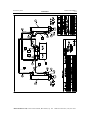
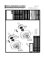
1
RAFNA INDUSTRIES LIMITED
19300 Clark -Graham, Baie d’Urfe, Quebec
Tel: (514) 457 -4373 or 1-888-525 -3660
Fax: (514) 457-3567
MODEL R-250 HD
"CUSHION-RIDE" RAILGEAR
OPERATING, SERVICE AND
PARTS MANUAL
"ROTATING FRONT - ROTATING REAR”
READ THIS MANUAL BEFORE OPERATING
RAILGEAR EQUIPPED VEHICLE
Railgear Model:
CR-250HD-055
Application Models: 2001 GMC 2500HD (All Models *25***HD)
Issued July 2001
Bulletin MO25RRG
Issued July 2001
Bulletin MO25RRG
Note:
The appendix of this manual includes the latest changes to the installation and operation
of the railgear not included in the “body” of this manual.
Please refer to the appendix prior to installing and operating the railgear.
The information in the appendix supersedes whatever is mentioned in the “body” of this
manual.
Rafna Industries Ltd, 19300 Clark-Graham, Baie d’Urfe, Qc Tel: 1-888-525-3660 Fax: (514) 457-3567
Issued July 2001
Bulletin MO25RRG
TABLE OF CONTENTS
General Information
Safety Information
Description
Warranty
Serial Numbers
Specifications
Section 1
1-2
1-3
1-4
1-8
1-9
Operation
Inspections Before Operation
Placing Vehicle On The Track
Travelling On Rail
Braking On Rail
Removing Vehicle From The Track
Section 2
2-2
2-3
2-7
2-7
2-8
Service
Railgear Alignment
Rail Wheel Bearing Adjustment
Rail Wheel Load Adjustment
Routine Railgear Service
Hydraulic System Relief Valve Setting
Electrical System Troubleshooting
Section 3
3-2
3-7
3-9
3-12
3-17
3-18
Parts
Section 4
4-2
4-3
4-4
4-5
4-6
4-7
4-8
4-9
4-10
4-11
4-12
4-13
4-14
4-15
Rotating Front Railgear Assembly
Rotating Front Railgear Lock Up Assembly
Rotating Rear Railgear Assembly
Rotating Rear Railgear Lock Up Assembly
Rail Wheel Assembly
Rail Sweep Assembly
Steering Wheel Lock Assembly
Front Railgear Bumper Assembly
Truck Wheel Modification Assembly
Front Railgear Mounting Assembly
Rear Railgear Mounting Assembly
Railgear Hydraulic Assembly
Railgear Electrical Assembly
Railgear Pump Assembly
Appendix
Section 5
Rafna Industries Ltd, 19300 Clark-Graham, Baie d’Urfe, Qc Tel: 1-888-525-3660 Fax: (514) 457-3567
Issued July 2001
GENERAL INFORMATION
Bulletin MO25RRG
1-1
S ECTION 1: GENERAL INFORMATION
SAFETY INFORMATION
1-2
DESCRIPTION
1-3
WARRANTY
1-4
SERIAL NUMBERS
1-8
SPECIFICATIONS
1-9
Rafna Industries Ltd, 19300 Clark-Graham, Baie d’Urfe, Qc Tel: 1-888-525-3660 Fax: (514) 457-3567
Issued July 2001
GENERAL INFORMATION
1.0
Bulletin MO25RRG
1-2
SAFETY INFORMATION
WARNING:
§
Read this manual completely before attempting operation of the railgear
equipped vehicle.
§
Before any maintenance or adjustments are performed under the vehicle or
railgear, ensure the vehicle engine is turned off and the parking brake is set.
§
Ensure that positions and functions of all railgear controls are known before
attempting operation.
§
Ensure all body parts and loose clothing are clear of any moving parts of the
equipment.
§
If misalignment of the railgear equipment is indicated, promptly perform the
alignment procedure.
§
Do not operate the railgear equipped vehicle at speeds in excess of 70 km/h
(45 MPH) on rail. Rail travel speed should always be in conformance with
rail company regulations and should be reduce during incleme nt weather,
passing through road crossings, switches, frogs, bridges and curves of more
than 2 degrees. Curves of greater than 20 degrees should be negotiated with
extreme caution. Operation of this vehicle at unsafe speeds could result in
derailment.
§
Ensure that the railgear mechanical lock-ups on both the front and rear units
are engaged positively before initiating highway or rail travel.
§
The railgear equipped vehicle has an increased turning radius. Exercise
caution when operating as sharp corners may be difficult to negotiate.
§
The following safety precautions should be taken before vehicle is operated:
ü
ü
ü
ü
Visually inspect the railgear prior to use for damaged or worn parts
Check for loose wheels and fasteners
Check for leaking hydraulic lines and cylinders
Check for proper lubrication
Failure to heed to any of the above mentioned warnings could result in severe
bodily injury and equipment damage.
Rafna Industries Ltd, 19300 Clark-Graham, Baie d’Urfe, Qc Tel: 1-888-525-3660 Fax: (514) 457-3567
Issued July 2001
GENERAL INFORMATION
2.0
Bulletin MO25RRG
1-3
DESCRIPTION
This manual covers the operation, parts and service of the Rafna Industries rotating front
and rotating rear R-250 HD railgear units as applicable to multiple vehicles. If necessary,
any difference in operation, parts or service for specific vehicle and/or railgear models is
clearly detailed by separate instructions for each. Otherwise, the operation, parts and
service instructions are the same for all models. Please refer to the appendix for the latest
additions that have not been included in this manual.
The Rafna Industries R-250 HD railgear is a hydraulically operated road-to-rail
conve rsion system applicable to vehicles of up to 12,500 lbs G.V.W.R. The front and
rear railgear units are frame mounted systems which are hydraulically raised and
lowered. The hydraulic power is supplied by a 12VDC electrical / hydraulic pump.
During highway and rail travel, the front and rear railgear units are mechanically locked
in position. A steering wheel lock system keeps the vehicle’s front wheels straight during
rail travel. The railgear’s spring suspension system ensures constant wheel to rail contact
and a comfortable ride. On-rail propulsion is provided by the vehicle’s rear tires’ contact
with the rail. On-rail braking is accomplished through the vehicle’s original braking
system.
This manual uses the orientation convention for the vehicle as shown in figure 1-1.
Rafna Industries Ltd, 19300 Clark-Graham, Baie d’Urfe, Qc Tel: 1-888-525-3660 Fax: (514) 457-3567
Issued July 2001
GENERAL INFORMATION
3.0
Bulletin MO25RRG
1-4
WARRANTY
RAFNA INDUSTRIES LTD.,
LIMITED WARRANTY
Rafna Industries’ warranty covers a period of TWELVE (12) months after the date of the rail
gear’s entry into service. The warranty asserts that each new rail gear sold will be free from
defects in material and workmanship under normal use and service. Rafna’s obligation under this
warranty is limited to repairing or replacing at its factory, or other locations as designated by the
company. Any defective part or parts must be returned within 30 days of the date of failure or
notice of defect for factory inspection or as designated by Rafna Industries Ltd.
Equipment or parts not manufactured by Rafna Industries, but which are furnished in connection
with Rafna products are covered directly and solely by the warranty of the original equipment
manufacturer supplying them.
The obligation of Rafna Industries under this warranty is limited to the replacement of parts that
appear to be defective after review and inspection by our firm or designated representative. This
warranty does not oblige Rafna Industries to bear the customer’s cost of labor or transportation
charges concerning the return of defective parts. However, if found to be defective the outbound
direct ground freight on the part will be prepaid to locations within continental United States and
Canada by Rafna Industries Ltd. The warranty does not cover responsibility for customer’s claims
arising from abuse, misuse, neglect, or alteration of the rail gear. All claims are subject to
inspection of said parts by our firm.
This warranty is in lieu of other warranties, expressed or implied, including any implied
warranties of merchantability or fitness for a particular purpose and any liability for special or
consequential damages.
PRODUCT IMPROVEMENT LIABILITY DISCLAIMER
Rafna Industries Ltd., reserves the right to make any changes in or improvements on its products
without incurring any liability or obligation whatever and without being required to make any
corresponding changes or improvements in products previously manufactured or sold.
IMPORTANT NOTICE
This warranty will be considered void if Rafna Industries’ Installation instructions or Service and
Maintenance schedule is not followed according to the detailed instructions contained in both our
Installation Manual and our Operation and Service Manual.
Rafna Industries Ltd, 19300 Clark-Graham, Baie d’Urfe, Qc Tel: 1-888-525-3660 Fax: (514) 457-3567
Issued July 2001
GENERAL INFORMATION
Bulletin MO25RRG
1-5
WARRANTY POLICIES AND PROCEDURES FOR
INSTALLERS AND CUSTOMERS
Installers & Customer Warranty:
To prevent unnecessary delays or misunderstandings in handlin g Installers or Customers
warranty claims, it is required that all warranty requests be authorized prior to any
repairs, modifications or adjustments being started.
Warranty information and authorization can be obtained from Rafna Industries Vice
President – Engineering or Customer Service Manager who can be contacted at: 1-888525-3660.
Rafna’s warranty will not apply if the Railgear or any of its components have been
modified or replaced without the written consent of the company.
Additional Billing, Installers & Customers:
If, during installation, it is found that incorrect parts have been shipped. Rafna will cover
all costs involved in replacing these parts and return of incorrectly shipped parts.
All warranty claims concerning short / incorrect shipment of parts or accessories must be
made within 30 days of delivery.
In order to maintain control over extra or additional billing due to incorrect shipments,
only the Vice President – Engineering or Customer Service Manager can issue a Purchase
Order authorizing replacement parts, shipping or work to be performed by an outside
source.
Warranty Claim information and requirements:
Rafna Industries will require the following information at time of claim as well as the a
properly filled out “Warranty Claim Form” form reference war #1/03.00
Information Required:
1) Customer Purchase Order number.
2) Rafna railgear serial number.
3) Vehicle unit number.
4) Vehicle VIN number.
5) Purchaser of Rafna railgear.
6) Date of purchase.
7) Name of end user.
8) Company requesting warranty claim.
9) Ship to Address.
10) Bill to Address.
Rafna Industries Ltd, 19300 Clark-Graham, Baie d’Urfe, Qc Tel: 1-888-525-3660 Fax: (514) 457-3567
Issued July 2001
GENERAL INFORMATION
Bulletin MO25RRG
1-6
On approval of warranty claim, the Installer or Customer will issue a Purchase Order to
Rafna Industries Ltd. to cover the defective parts and out bound freight for part values
exceeding $50.00 US and $75.00 CDN. Rafna will in turn ship all required parts pre-paid
ground direct to the Installer or Customer. On receipt of claimed warranty parts, Rafna
or their sub supplier will inspect defective parts and if deemed warranty, a credit will be
issued to the Installer or Customer. If claimed warranty parts are not received within 30
days, a credit will not be issued.
Labor Warranty and /or additional labor charges:
Labor or additional labor charges such as travel are not covered by either the Rafna
Warranty or any of Rafna’s sub-suppliers.
Faulty Railgear Installations:
If a warranty claim arises due to incorrect installation by an installer who has not
followed the written instructions as out lined in our manual or as trained by either
Rafna Customer Service or Sales Department, warranty claims will not be honored.
Parts Warranty:
Rafna manufactured parts will be warranted and replaced if found to be defective due to
poor materials or workmanship for up to one year from date of the railgear’s entry into
service. Parts not manufactured by Rafna Industries Ltd., will be covered by the Original
Equipment Manufactures warranty. Based on the OEM’s investigation of the warranty
claim against their manufactured component their decision will stand.
Rafna Industries Ltd, 19300 Clark-Graham, Baie d’Urfe, Qc Tel: 1-888-525-3660 Fax: (514) 457-3567
Issued July 2001
Bulletin MO25RRG
1-7
GENERAL INFORMATION
WARRANTY CLAIM FORM
This form must be completed prior to starting any warranty work
Warranty # War01-XXXX
Customer
Date
Tel/Fax
Railgear S/N
Vehicle No.
Vehicle VIN
End User
Date of Purchase
P.O. Number
Ref #
Inv. Address
Ship to Address
Inv. Address
Ship to Address
Inv. Address
Ship to Address
Inv. Address
Ship to Address
Shipping instructions:
Standard
Ground
Special
Air
Shipper:
PART No.
QUANTITY
Standard
5 day +
Way Bill #
Select
3 day
Expedition
2-3 day
Express
2 day
DESCRIPTION
PROBLEM DESCRIPTION
Required Documentation from the Customer
Description of Rafna Parts (Ordered or Used)
Invoice #
(For issuing Credit)
Total Claimed $
RAFNA INDUSTRIES approved by:
US/CAD
DATE:
CUSTOMER’S REPRESENTATIVE: _________________________________ DATE: _______________
For Internal Use only:
Engineering
Manufacturing
5825
Shipping
5826
Outside Supplier
5821
5820
Service
5822
Installation
5824
5823
Rafna Industries Ltd, 19300 Clark-Graham, Baie d’Urfe, Qc Tel: 1-888-525-3660 Fax: (514) 457-3567
Issued July 2001
GENERAL INFORMATION
4.0
Bulletin MO25RRG
1-8
SERIAL NUMBERS
Following receipt of this manual, the serial numbers, model numbers and date of
manufacture for both the front and rear railgear units should be recorded below for future
reference. This information is located on the identification plates (figure 1-2) mounted
on the railgear main frames.
Front Railgear Unit:
Serial Number:
__________________
Model Number:
__________________
Date of Manufacture: __________________
Rear Railgear Unit:
Serial Number:
__________________
Model Number:
__________________
Date of Manufacture: __________________
Rafna Industries Ltd, 19300 Clark-Graham, Baie d’Urfe, Qc Tel: 1-888-525-3660 Fax: (514) 457-3567
Issued July 2001
Bulletin MO25RRG
1-9
GENERAL INFORMATION
5.0
SPECIFICATIONS
Item
Installed Weight…...……………………………………...
Maximum Vehicle Load Rating………………………….
Track Gauge……………………………………………...
Wheel Diameter…………………………………………..
Metric
281 Kg
5680 Kg
1435 mm
245 mm
SAE
630 lbs
12,500 lbs
56 ½ in
10 in
Rafna Industries Ltd, 19300 Clark-Graham, Baie d’Urfe, Qc Tel: 1-888-525-3660 Fax: (514) 457-3567
Issued July 2001
OPERATION
Bulletin MO25RRG
2-1
S ECTION 2: OPERATION
INSPECTIONS BEFORE OPERATION
2-2
P LACING VEHICLE ON THE TRACK
2-3
T RAVELLING ON RAIL
2-7
BRAKING ON RAIL
2-7
REMOVING VEHICLE FROM THE TRACK
2-8
Rafna Industries Ltd, 19300 Clark-Graham, Baie d’Urfe, Qc Tel: 1-888-525-3660 Fax: (514) 457-3567
Issued July 2001
OPERATION
1.0
Bulletin MO25RRG
2-2
INSPECTIONS BEFORE OPERATION
Prior to each use of the railgear equipment, the following items should be inspected:
ü
ü
ü
ü
Check for damaged or worn parts
Check for loose wheels and/or fasteners
Check for leaking or damaged hydraulic lines, fittings, and cylinders
Check for proper lubrication at specified intervals
Also, the operator should ensure that the vehicle is in good operating condition by
following the vehicle manufacturer’s operating guide.
WARNING:
Following the first eight (8) hours of rail travel, an initial wheel bearing
inspection and verification of sufficient wheel bearing grease should be
performed. During this time period, the wheel bearings will have seated
themselves and may require adjustment of end-play. If the end -play is not in
accordance with specifications of 0.005”, bearing failure could occur and
would not be covered under the Rafna Industries Warranty. Refer to the
Service section of this manual for wheel bearing adjustment procedures.
Following the first 1000 km (625 Miles) of highway and rail travel, the
vehicle offset rim and wheel spacer retaining nuts should be re -torqued.
Refer to the Service section of this manual for re-torquing procedures.
On newly applied railgear equipment, ensure that the railgear and guide
wheel alignment procedure is performed before operation of the equipment.
Note that excessively worn guide wheels, vehicle pulling to one side while on
the rail, and vibrations through the vehicle while on the rail are indicators of
misaligned railgear or guide wheels. If any of these situations are
encountered, proceed to perform the alignment procedure as described in the
Service section of this manual as soon as possible to avoid damage to the
equipment and vehicle.
Rafna Industries Ltd, 19300 Clark-Graham, Baie d’Urfe, Qc Tel: 1-888-525-3660 Fax: (514) 457-3567
Issued July 2001
OPERATION
2.0
Bulletin MO25RRG
2-3
PLACING VEHICLE ON THE TRACK
WARNING:
§
Operating instruction provided below only address the Rafna Industries
railgear equipment. Applicable railway company procedures and policies
must be adhered to.
§
At level rail crossings, ensure that no other vehicles are approaching and
flag the crossing to ensure safety.
§
Understand equipment operation before operating equipment.
1. At a suitable location, drive the vehicle past the rail crossing and reverse onto and
parallel to the rails while aligning the rear railgear unit guide wheels directly over the
rails. At this point the front railgear unit guide wheels should be somewhat aligned
over the rails.
2. Place the vehicle automatic transmission in “PARK” (manual transmission in
“NEUTRAL”) and apply the parking brake. Energize the Railgear Pump by turning
on the respective dash switch. The dash switch light should come on at this point but
the railgear pump should not run yet. The railgear pump is an intermittent duty pump
which will only run while activating the front or rear push button controls.
3. Note that in order to align the front railgear guide wheels directly over the rails, the
rear railgear must be deployed first, then the vehicle is reversed until the front is
aligned.
4. The direction of hydraulic flow to the front and rear railgear is selected by pushing
the respective control box “Raise” or “Lower” push buttons. This energizes the front
or rear hydraulic solenoid valve and starts the pump motor.
5. Lower the rear railgear unit: (refer to figure 2-1)
a) Raise the railgear out of the mechanical locking system by selecting “Raise” on
the rear control (1).
b) Disengage the mechanical locking pin (2) by pulling the locking cable handle (3).
c) While holding the locking cable handle in this position, lower the railgear by
selecting “Lower” on the rear control.
d) Release the locking cable handle once the railgear has rotated below the highway
locked position.
e) Note that while the railgear is taking some of the vehicle’s load, the railgear
suspension (4) should be observed compressing. With the vehicle unloaded, the
nuts above the springs should be about 1” above the spring plate once the railgear
is fully deployed. If this is not the case, check for adequate lubrication. If the
inner tubes are not free to move, the spring suspension will not work correctly.
Rafna Industries Ltd, 19300 Clark-Graham, Baie d’Urfe, Qc Tel: 1-888-525-3660 Fax: (514) 457-3567
Issued July 2001
OPERATION
Bulletin MO25RRG
2-4
f) Continue lowering the railgear until the hydraulic cylinder (5) is fully extended
and the mechanical locking pin clicks into the rail locked position. In this
position, the railgear should be about vertical.
g) Release the rear control.
h) Ensure that the rear railgear is securely locked in position and correctly contacts
the rails before proceeding.
6. Lower the front railgear unit: (refer to figure 2-2)
a) With the rear railgear unit correctly deployed onto the rails, reverse the vehicle
until the front railgear guide wheels are directly over the rails.
b) Place the vehicle’s automatic transmission in “PARK” (manual transmission in
“NEUTRAL”), apply the parking brake, and re -energize the Railgear Pump if
required by turning on the respective dash switch.
c) Raise the railgear out of the mechanical locking system by selecting “Raise” on
the front control (1).
d) Release the mechanical locking pin (2) from the highway locked position by
moving the locking handle (3) towards the left side of the vehicle. Hold the
locking handle in this position.
e) Lower the railgear by selecting “Lower” on the front control.
f) Release the locking handle once the railgear has rotated below the highway
locked position.
g) Note that while the railgear is taking some of the vehicle’s load, the railgear
suspension (4) should be observed compressing. With the vehicle unloaded, the
nuts above the springs should be about 1” above the spring plate once the railgear
Rafna Industries Ltd, 19300 Clark-Graham, Baie d’Urfe, Qc Tel: 1-888-525-3660 Fax: (514) 457-3567
Issued July 2001
OPERATION
Bulletin MO25RRG
2-5
is fully deployed. If this is not the case, check for adequate lubrication. If the
inner tubes are not free to move, the spring suspension will not work correctly.
h) The railgear moves down into position on the rails until the hydraulic cylinder (5)
is fully extended and the mechanical locking pin clicks the into rail locked
position. In this position, the railgear should be about vertical.
i) Release the front control.
j) Ensure that the railgear is securely locked in position and correctly contacts the
rails before proceeding.
7. De-energize the Railgear Pump by turning off the respective dash switch.
8. Engage the steering wheel lock system: (refer to figure 2-3)
a) Turn the steering wheel (1) until the front tires point straight ahead.
b) Pass the steering lock (2) over the horn cover and into the steering column lock
retainer (3).
c) Ensure the steering lock secures the steering wheel and does not interfere with the
driver’s air bag cover.
Rafna Industries Ltd, 19300 Clark-Graham, Baie d’Urfe, Qc Tel: 1-888-525-3660 Fax: (514) 457-3567
Issued July 2001
OPERATION
Bulletin MO25RRG
2-6
Rafna Industries Ltd, 19300 Clark-Graham, Baie d’Urfe, Qc Tel: 1-888-525-3660 Fax: (514) 457-3567
Issued July 2001
OPERATION
3.0
Bulletin MO25RRG
2-7
TRAVELLING ON RAIL
Before proceeding to travel on the rail, ensure that the railgear pump has been de energized, that the railgear cylinders are fully extended, that the front and rear
mechanical locks are securely engaged, and that the steering wheel lock has been
installed with the front wheels pointing straight ahead.
WARNING:
§
Do not operate the vehicle in excess of 70 km/hr (45 MPH) on the track.
Railroad rules governing on rail travel must be observed at all times.
§
Do not operate vehicle on track if the ve hicle load exceeds the maximum
load rating of the railgear.
§
Do not operate the vehicle on track if the steering wheel lock is not
engaged.
§
Do not operate the vehicle on track if the Railgear Pump is energized.
§
Do not operate the vehicle on track if the front or rear mechanical locks
are not securely engaged
The vehicle may now be driven as if on the highway at a reduced speed. The steering
wheel should not be touched; it should be allowed to float in the steering wheel lock.
Note also that braking dis tance is increased while on the track.
4.0
BRAKING ON RAIL
This railgear equipment allows the vehicles tire contact with the rail to provide the
braking action, identically as if on the highway. However, it is important to apply the
brakes gradually in order to avoid locking up the vehicle tires. Note also that stopping
distance while on the track is greater than when on the highway and braking ability can
be adversely effected during inclement weather.
Rafna Industries Ltd, 19300 Clark-Graham, Baie d’Urfe, Qc Tel: 1-888-525-3660 Fax: (514) 457-3567
Issued July 2001
OPERATION
5.0
Bulletin MO25RRG
2-8
REMOVING VEHICLE FROM THE TRACK
WARNING:
§
Operating instruction provided below only address the Rafna Industries
railgear equipment. Applicable railway company procedures and policies
must be adhered to.
§
At level rail crossings, ensure that no other vehicles are approaching and
flag the crossing to ensure safety.
§
Understand equipment operation before operating equipment.
1. Approach a level crossing or other suitable location, and prepare to remove the
vehicle from the track by placing the automatic transmission in “PARK” (manual
transmission in “NEUTRAL”) and applying the parking brake.
2. Energize the Railgear Pump by turning on the respective dash switch. The dash
switch light should come on at this point but the railgear pump should not run yet.
The railgear pump is an intermittent duty pump which will only run while activating
the front or rear push button controls.
3. Note that the vehicle is removed from the track by first raising the front railgear and
then raising the rear railgear. Finally the steering wheel lock is removed.
4. The direction of hydraulic flow to the front and rear railgear is selected by pushing
the respective control box “Raise” or “Lower” push button. This energizes the front
or rear hydraulic solenoid valve and starts the pump motor.
5. Raise the front railgear unit: (refer to figure 2-2)
a) Disengage the mechanical locking pin (2) by moving and holding the locking
handle (3) to the left side of the vehicle. It may be necessary to lower the railgear
slightly in order to release the pressure on the locking pin.
b) Raise the railgear unit by selecting “Raise” on the front control (1).
c) Release the locking handle once the railgear has rotated past the rail locked
position.
d) Continue raising the railgear unit until the mechanical locking pin clicks into the
highway locked position (the hydraulic cylinder will be retracted).
e) Release the hydraulic pressure in the cylinder by selecting “Lower” on the front
control. The railgear should rest on the locking pin.
f) Ensure the mechanical locking pin is correctly engaged before proceeding.
Rafna Industries Ltd, 19300 Clark-Graham, Baie d’Urfe, Qc Tel: 1-888-525-3660 Fax: (514) 457-3567
Issued July 2001
OPERATION
Bulletin MO25RRG
2-9
6. Raise the rear railgear unit: (refer to figure 2-1)
a) Disengage the mechanical locking pin (2) by moving and holding the locking
cable handle (3) to the left side of the vehicle. It may be necessary to lower the
railgear slightly in order to release the pressure on the locking pin.
b) Raise the railgear unit by selecting “Raise” on the rear control (1).
c) Release the locking cable handle once the railgear has rotated past the rail locked
position.
d) Continue raising the railgear unit until the mechanical locking pin clicks into the
highway locked position (the hydraulic cylinder will be completely retracted).
e) Release the hydraulic pressure in the cylinder by selecting “Lower” on the rear
control. The railgear should rest on the locking pin.
f) Ensure the mechanical locking pin is correctly engaged before proceeding.
7. De-energize the Railgear Pump by turning off the respective dash switch.
8. Disengage the steering wheel lock: (refer to figure 2-3)
a) Pull the steering lock (2) out of the lock retainer (3).
b) Store the steering lock in a secure spot.
WARNING:
§
Before proceeding with highway travel, ensure both the front and rear
railgear units are securely seated in their respective mechanical locking
systems.
§
Ensure that the railgear pump has been de -energized.
9. Carefully drive the vehicle off the track and onto the highway.
Rafna Industries Ltd, 19300 Clark-Graham, Baie d’Urfe, Qc Tel: 1-888-525-3660 Fax: (514) 457-3567
Issued July 2001
SERVICE
Bulletin MO25RRG
3-1
SECTION 3: SERVICE
RAILGEAR ALIGNMENT
3-2
RAIL WHEEL BEARING ADJUSTMENT
3-7
RAIL WHEEL LOAD ADJUSTMENT
3-9
ROUTINE RAILGEAR SERVICE
3-12
HYDRAULIC SYSTEM RELIEF VALVE SETTING
3-17
ELECTRICAL SYSTEM T ROUBLESHOOTING
3-18
Rafna Industries Ltd, 19300 Clark-Graham, Baie d’Urfe, Qc Tel: 1-888-525-3660 Fax: (514) 457-3567
Issued July 2001
SERVICE
1.0
Bulletin MO25RRG
3-2
RAILGEAR ALIGNMENT
This railgear equipment must be correctly aligned in order to perform properly and avoid
excessive wear on the equipment. All four rail wheels may be independently aligned
while lateral adjustment of the front and rear railgear is accomplished through adjusting
the railgear on the mounting plates. A parallel line system and the following procedure
should be used to perform the railgear alignment. Rafna Industries can also supply a
special alignment tool kit (Order 2 x R-066AD and 2 x R-066AP) with which separate
instructions are supplied.
WARNING:
§
The vehicle tires should have been aligned following installation of the
railgear and prior to performing the railgear alignment.
§
This procedure should be done with the vehicle parked on straight level
track with the front tires pointing straight ahead in order to achieve
correct alignment.
§
Before any maintenance or adjustments are performed under the vehicle
or railgear, ensure the engine is turned off and the parking brake is set.
1. Ensure the vehicle tires have been aligned following the installation of the railgear
and prior to performing the railgear alignment.
2. Lower the front and rear railgear units to the rail position on a straight level section of
track.
3. Ensure the vehicle front tires are pointing straight ahead and engage the steering lock.
4. Set up a parallel string line system about 6 inches above the head of the rail as
follows: (refer to figure 3-1)
a) Fabricate two metal alignment bars with ½” diameter posts on each end about 7”
tall and about 9’ apart. Create a circumferencial groove in each post about 1”
from the top to hold the string lines. Ensure that the two alignment bars are
fabricated identical to within 1/32” tolerance. The location of the posts on the
alignment bars will ensure that dimensions A and B are equal.
b) Fasten the alignment bars to the head of the rail about 2’ ahead of and behind the
vehicle. Ensure that the alignment bars are perpendicular to the rail and can be
slid side to side for adjustment. The location of the alignment bar posts will
ensure that dimensions C and D are equal.
c) Run a string line from the front alignment bar post to the rear alignment bar post
on each side of the vehicle using the grooves cut in the posts.
d) Ensure that dimensions A and B are equal, and dimensions C and D are equal.
Rafna Industries Ltd, 19300 Clark-Graham, Baie d’Urfe, Qc Tel: 1-888-525-3660 Fax: (514) 457-3567
Issued July 2001
SERVICE
Bulletin MO25RRG
3-3
5. Proceed to adjust the side to side location of the alignment bars until the distance
between each vehicle front rim and each string line is equal (dimensions E and F
equal) and the distance between each vehicle rear rim and each string line is equal
(dimensions G and H equal). Note that dimensions E and F may not equal
dimensions G and H.
6. Railgear wheel alignment:(refer to figure 3-1 and 3-2)
a) Secure an 18” long straightedge to the backside of each railgear wheel flange.
b) Measure the distance between the front-most and rear-most points of each
straightedge and the parallel lines (dimensions I, J, K, and L in the front and M,
N, O, and P in the rear).
c) With a tolerance of 1/16”, dimensions I and J should be equal, dimensions K and
L should be equal, dimensions M and N should be equal, and dimensions O and P
should be equal. If this is not the case, proceed to adjust the rail wheel alignment.
Otherwise, proceed to step 7.
d) Loosen the four bolts and nuts (1) securing each railgear wheel spindle housing
(2) to the railgear axles (3) such that the wheels are free to rotate on the horizontal
plane yet snug enough to stay in place.
e) Adjust each wheel to the centered position (dimension I & J equal, K & L equal,
M & N equal, and O & P equal). Note that dimensions I & J may not equal K &
L and M & N may not equal O & P at this point.
f) Re-torque the rail wheel fasteners to specifications.
g) Remove the straightedges.
Rafna Industries Ltd, 19300 Clark-Graham, Baie d’Urfe, Qc Tel: 1-888-525-3660 Fax: (514) 457-3567
Issued July 2001
SERVICE
Bulletin MO25RRG
3-4
WARNING:
§
When adjusting the lateral alignment of the front and rear railgear, do
not use any force against the suspension guide tube assemblies that may
cause damage which would restrict the suspension movement of the
railgear.
7. Front railgear lateral alignment: (refer to figure 3-1 and 3-3)
a) Secure a straightedge to the backside of each front rail wheel flange.
b) Measure distance from the front-most and rear-most points of the two
straightedges to the parallel lines (dimensions I, J, K, and L).
c) If these measurements are within 1/8” tolerance, proceed to step 8. Otherwise
continue to step 7 d).
d) Raise the railgear off the track and loosen the four bolts (1) that secure the
railgear unit (2) to the front mounting plates (3).
e) Move the railgea r unit laterally until dimensions I, J, K, and L are equal to within
1/8” tolerance.
f) Re-torque the four mounting bolts to specifications.
g) Remove the two straightedges and lower the railgear to rail position.
Rafna Industries Ltd, 19300 Clark-Graham, Baie d’Urfe, Qc Tel: 1-888-525-3660 Fax: (514) 457-3567
Issued July 2001
SERVICE
Bulletin MO25RRG
3-5
8. Rear railgear lateral alignment: (refer to figure 3-1 and 3-4)
a) Secure a straightedge to the back side of each rear rail wheel flange.
b) Measure distance from the front-most and rear-most points of the two
straightedges to the parallel lines (dimensions M,N,O,P).
c) If these measurements are within 1/8” tolerance, proceed to step 9. Otherwise
continue to step 8. d).
d) Raise the railgear off the track and loosen the four bolts (1) that secure the
railgear unit (2) to the rear mounting plates (3).
e) Move the railgear unit laterally until dimensions M,N,O,P are equal to within 1/8”
tolerance.
f) Re-torque the four mounting bolts to specifications.
g) Remove the two straightedges and lower the railgear to the rail position.
9. Remove the parallel line system
10. Remove the vehicle from the rails.
Rafna Industries Ltd, 19300 Clark-Graham, Baie d’Urfe, Qc Tel: 1-888-525-3660 Fax: (514) 457-3567
Issued July 2001
SERVICE
Bulletin MO25RRG
3-6
Rafna Industries Ltd, 19300 Clark-Graham, Baie d’Urfe, Qc Tel: 1-888-525-3660 Fax: (514) 457-3567
Issued July 2001
SERVICE
2.0
Bulletin MO25RRG
3-7
RAIL WHEEL BEARING ADJUSTMENT
The front and rear railgear wheel bearings will need to be adjusted if the wheel end-play
exceeds 0.005”. Recommended end-play range is from 0.003” to 0.004”. If the bearings
are not adjusted, bearing failure could occur and this would not be covered under the
Rafna Industries Warranty.
If the end-play is not in conformance with this specification, adjust the wheel bearings as
follows: (refer to figure 3-5)
WARNING:
§
Before any maintenance or adjustments are performed unde r the vehicle
or railgear, ensure the engine is turned off and the parking brake is set.
1. Perform this procedure with the railgear in the highway position and with the railgear
wheels free to turn.
2. Access the wheel bearings: Remove the wheel hub cap (1) and gasket (2) by
unbolting the three hub cap retaining bolts (3).
3. Adjust the wheel bearing:
a)
b)
c)
d)
e)
Remove spindle nut cotter pin (4).
While rotating the wheel forward, torque the wheel spindle nut (5) to 20 ft-lbs.
Loosen the spindle nut slightly until it is “just loose”.
Re-torque the spindle nut to 6 ft-lbs.
Install a new cotter pin through the spindle nut and spindle. If the cotter pin holes
do not line up, tighten the spindle nut until the holes align. Do not tighten more
than ½ flat of the nut.
f) Ensure there is sufficient grease in the wheel bearing cavity.
g) Re-install the gasket and hub cap. Torque the hub cap retaining bolts to
specifications.
If a torque wrench is not available, the following procedure may be substituted for steps
3. b) through 3. d) above:
a) Tighten the spindle nut until the wheel cannot be turned by hand.
b) Loosen the spindle nut until the wheel can be turned by hand and the cotter pin
can be installed.
c) Re-adjust when torque wrench is available.
Rafna Industries Ltd, 19300 Clark-Graham, Baie d’Urfe, Qc Tel: 1-888-525-3660 Fax: (514) 457-3567
Issued July 2001
SERVICE
Bulletin MO25RRG
3-8
Rafna Industries Ltd, 19300 Clark-Graham, Baie d’Urfe, Qc Tel: 1-888-525-3660 Fax: (514) 457-3567
Issued July 2001
SERVICE
3.0
Bulletin MO25RRG
3-9
RAIL WHEEL LOAD ADJUSTMENT
The percentage of the vehicle load carried by the railgear wheels must be properly
adjusted to ensure sufficient traction and guidance and to avoid overloading of the
railgear equipment. The load on the rail wheels is an indicator of the amount of load
carried by the railgear and is adjusted as described below with a hydraulic bottle jack.
This adjustment is done at installation and only requires re-adjustment if the railgear is
moved or vehicle equipment is changed. The load need not be adjusted with every minor
load change in the vehicle.
WARNING:
§
Before any maintenance or adjustments are performed under the vehicle
or railgear, ensure the engine is turned off and the parking brake is set.
§
The vehicle should not be carrying any load during this procedure.
§
Ensure an inspection of the railgear units has been carried out before any
track testing is performed.
1. Place the vehicle on a level section of rail with the railgear deployed to the rail
position.
2. Ensure that the vehicle tires are not in contact with any obstructions except the rails
and that they are inflated to the correct air pressure.
3. Check each rail wheel load as follows: (refer to figure 3-6)
a) Place the jack (1) on a solid railway tie (2) beneath the rail wheel spindle housing
(3) and jack the rail wheel off the rail.
b) Insert a piece of paper (4) between the rail and the rail wheel and lower the jack
until the rail wheel squeezes the paper so that it cannot be pulled out.
c) Slowly jack up the rail wheel while pulling on the paper. Whe n the paper can be
pulled out, stop jacking.
d) Record the weight reading on the jack and compare to the minimum required load
in Table 3-1.
Table 3-1: Minimum Required Rail Wheel Load
Front Rail Wheel Load:
700 – 800 lbs
Rear Rail Wheel Load:
450 – 500 lbs
(Note: Different size jacks will show different hydraulic pressure readings while
lifting identical weights. This manual therefore specifies railwheel load in terms of
weight not pressure.)
Rafna Industries Ltd, 19300 Clark-Graham, Baie d’Urfe, Qc Tel: 1-888-525-3660 Fax: (514) 457-3567
Issued July 2001
SERVICE
Bulletin MO25RRG
3-10
4. If the load on the rail wheels are not within the specifications listed in Table 3-1,
adjust as follows: (refer to figure 3-7)
a) Raise the railgear until the rail wheels are unloaded.
b) Loosen the jam nuts (1) under each lower spring plate (2) and the upper lock nuts
(3) above each upper spring plate.
c) Adjust the lower spring plates and upper lock nuts up to increase the load or down
to decrease the load on the rail wheels. Each side should be moved the same
amount.
d) The acceptable range of adjustment on the lower spring plates is 1½” – 3” from
bottom of lower spring plate to the top of axle. If the correct loads cannot be
obtained within this range, adjust the height of the railgear in the mounting plate
holes.
e) Lower the railgear and recheck each rail wheel load. Re-adjust if necessary.
f) Tighten the jam nuts against the lower spring plates.
g) Raise the railgear and tighten the upper lock nuts until the rubber springs just start
to compress. Do not pre-compress the rubber springs.
h) Lower the railgear to the rail position. The upper lock nut should be about ¾” –
1” above the upper spring plate.
i) Raise the railgear to the highway position.
Rafna Industries Ltd, 19300 Clark-Graham, Baie d’Urfe, Qc Tel: 1-888-525-3660 Fax: (514) 457-3567
Issued July 2001
SERVICE
Bulletin MO25RRG
3-11
WARNING:
§
The rail wheels must be a minimum of 7 ½” above the ground when in
the highway position. If this minimum distance cannot be met with the
correct rail wheel loads and the holes available in the mounting plates,
contact Rafna Industries.
Rafna Industries Ltd, 19300 Clark-Graham, Baie d’Urfe, Qc Tel: 1-888-525-3660 Fax: (514) 457-3567
Issued July 2001
SERVICE
4.0
Bulletin MO25RRG
3-12
ROUTINE RAILGEAR SERVICE
The front and rear railgear must be serviced to ensure proper operation and avoid damage
to the equipment. Refer to table 3-2 for the Recommended Se rvice Schedule.
Grease fittings are provided at all lubrication points on the Rafna Industries railgear and
are located in figures 3-8 and 3-9. The recommended lubricant for this equipment is
ESSO LONAX EP2 GREASE or equivalent (operating range –30°C to 135°C) for all
lubrication points. In cold weather areas and/or winter seasons, use low temperature
grease such as SHELL DARINA XL 102.
Torque truck rim lug nuts to 125 – 165 ft-lbs as per sequence shown in figure 3-10.
Should any loose nuts and bolts be encountered on the railgear during the inspections or
during maintenance of the railgear units, first refer to figures 3-11 & 3-12 for nonstandard bolt torques and then to table 3-3 for standard bolt torques.
WARNING:
§
If the vehicle should derail, a thorough inspection of the complete railgear
assemblies for damaged parts should be carried out before the units are
put back into service.
Rafna Industries Ltd, 19300 Clark-Graham, Baie d’Urfe, Qc Tel: 1-888-525-3660 Fax: (514) 457-3567
Issued July 2001
Bulletin MO25RRG
3-13
SERVICE
Monthly
Every 3
Months
Every 6
Months
1
Visually inspect the railgear prior to use for
damaged or worn parts.
ü
ü
ü
ü
ü
2
Check for loose rail wheels and fasteners.
ü
ü
ü
ü
ü
3
Ensure the rail gear locking mechanism is
functioning properly in both the road and
rail positions.
ü
ü
ü
ü
ü
4
Check and adjust truck tire pressure as per
vehicle specifications.
ü
ü
ü
ü
ü
5
Ensure the vehicle is in good operating
condition based on the vehicle operating
and maintenance instructions.
ü
ü
ü
ü
ü
6
Check and adjust rail wheel end play
(0.005” max.).
ü
ü
7
Inspect railgear wheel flanges for wear.
Use the “Rafna Wheel Flange Indicator” for
measurement.
ü
ü
ü
ü
8
Inspect all hydraulic fittings and hoses for
leaks or wear.
ü
ü
ü
ü
9
Inspect rail sweeps for close proximity to
rail head.
ü
ü
ü
ü
10
Torque truck rim lock nuts.
ü
ü
ü
ü
11
Grease hydraulic cylinder pivot points.
ü
ü
ü
12
Grease inner tube lower pivot points.
ü
ü
ü
13
Grease inner tubes.
ü
ü
ü
14
Grease locking mechanism.
ü
ü
ü
15
Check fluid level in hydraulic reservoir.
Top off with appropriate filtered fluid.
ü
ü
ü
16
Grease rail wheel bearings (3 months or
3,000 rail kms (1,900 rail miles), whichever
is less).
ü
ü
17
Inspect and repack rail wheel bearings.
ü
18
Perform rail wheel load check and railgear
alignment procedures.
ü
Daily
Weekly
Service Required
Initial 8hr
of Use
Table 3-2: Recommended Service Schedule
ü
ü
Rafna Industries Ltd, 19300 Clark-Graham, Baie d’Urfe, Qc Tel: 1-888-525-3660 Fax: (514) 457-3567
Issued July 2001
SERVICE
Bulletin MO25RRG
3-14
Rafna Industries Ltd, 19300 Clark-Graham, Baie d’Urfe, Qc Tel: 1-888-525-3660 Fax: (514) 457-3567
Issued July 2001
SERVICE
Bulletin MO25RRG
3-15
Rafna Industries Ltd, 19300 Clark-Graham, Baie d’Urfe, Qc Tel: 1-888-525-3660 Fax: (514) 457-3567
Issued July 2001
SERVICE
Bulletin MO25RRG
3-16
Table 3-3: Standard Bolt Torque Values
Bolt Detail
Bolt Torque Value (ft -lbs)
¾” UNC Gr. 8 Fasteners
175
5/8” UNC Gr. 8 Fasteners
150
½” UNC Gr. 8 Fasteners
100
3/8” UNC Gr. 8 Fasteners
40
¼” UNC Gr. 8 Fasteners
12
Rafna Industries Ltd, 19300 Clark-Graham, Baie d’Urfe, Qc Tel: 1-888-525-3660 Fax: (514) 457-3567
Issued July 2001
SERVICE
5.0
Bulletin MO25RRG
3-17
HYDRAULIC SYSTEM RELIEF VALVE SETTING
This system is equipped with one relief valve located on the railgear hydraulic pump.
The relief valve will require adjustme nt at installation and if ever there appears to be
inadequate hydraulic pressure to operate the railgear. Refer to figure 3-13 throughout the
following adjustment procedure.
1. Locate the hydraulic hose (1) that supplies the rod end of the front railgear hydraulic
cylinder (2) from the hydraulic pump pressure port (3) and disconnect it at the pump.
2. Install a test gauge (4) (up to 3000 PSI) between the disconnected hydraulic hose and
the pump pressure port. The pressure gauge will indicate the relief valve (5) setting
when the pump is loaded.
3. Raise the front railgear completely. Select the “Raise” position on the front control
so that the hydraulic cylinder creates a load on the pump by trying to dead-head. The
hydraulic pump should start and the pressure reading on the test gauge should climb
to 1800 PSI.
4. If the pressure is not correct, release the front control and adjust the external relief
valve on the pump accordingly.
5. Once the correct pressure on the pump relief valve is obtained, release the pressure in
the system and remove the test gauge. Re-connect all hydraulic lines.
Rafna Industries Ltd, 19300 Clark-Graham, Baie d’Urfe, Qc Tel: 1-888-525-3660 Fax: (514) 457-3567
Issued July 2001
SERVICE
6.0
Bulletin MO25RRG
3-18
ELECTRICAL SYSTEM TROUBLESHOOTING
The following basic tests can be performed to check the integrity of the railgear electrical
system. Refer to the electrical schematic in figure 3-14.
Should the hydraulic pump fail to operate, all wiring should be checked for shorts, the
fuse should be checked and the following tests should be performed.
1. Pump motor coil shift test and voltage test (use a Volt-Meter in Volts-DC mode):
a) Disconnect the wire from the coil “motor” terminal to the hydraulic pump motor.
b) Ensure the coil “batt” terminal is connected to the positive terminal of the battery
and the coil base is properly grounded. There should be 12V between the coil
“batt” terminal and the coil base and 0V between the coil “motor” terminal and
the coil base.
c) Connect one end of a short “shunt” wire to the coil switching terminal and touch
the other end to the coil “batt” terminal. The coil should shift in the housing
producing a distinctive “click”.
d) With the “shunt” wire connected as in step c), the voltage between the coil
“motor” terminal and the coil base should be 12V.
e) If the coil does not “click” and/or the voltage in step d) is not 12V then the coil is
inoperative and must be replaced.
2. Pump motor coil resistance test (use Ohm-Meter):
a) Disconnect all wiring to the coil.
b) Connect an Ohm-Meter to the coil switching terminal and to the coil base. The
resistance should be about 20 Ohms.
c) Connect an Ohm-Meter to the coil “motor” terminal and to the coil switching
terminal. The resistance should be infinite (open). No resistance with this
connection will indicate a shorted coil.
d) Connect an Ohm-Meter to the coil “batt” terminal and to the coil switching
terminal. The resistance should be infinite (open). No resistance with this
connection will indicate a shorted coil.
e) If the coil resistances are not within specifications, the coil must be replaced.
3. Pump motor test:
a) Disconnect the pump motor wire from the coil.
b) Ensure the pump base is properly grounded by running a ground strap from the
motor base to the negative battery terminal.
c) Connect one end of a large “shunt” wire to the pump motor positive terminal and
touch the other end to the battery positive terminal.
d) The pump motor should run upon touching the “shunt” wire.
e) If the pump does not run, the pump motor is defective.
Rafna Industries Ltd, 19300 Clark-Graham, Baie d’Urfe, Qc Tel: 1-888-525-3660 Fax: (514) 457-3567
Issued July 2001
SERVICE
Bulletin MO25RRG
3-19
Should the pump motor start running immediately following turning on the respective
dash switch, all wiring should be checked for shorts and the following should be
performed.
1. Check the front and rear control switches for sticking or shorting out.
2. Disconnect the wire from the coil switching terminal. If the pump continues to run,
then the coil is defective.
Rafna Industries Ltd, 19300 Clark-Graham, Baie d’Urfe, Qc Tel: 1-888-525-3660 Fax: (514) 457-3567
Issued July 2001
PARTS
Bulletin MO25RRG
4-1
SECTION 4: P ARTS
ROTATING FRONT RAILGEAR ASSEMBLY
4-2
ROTATING FRONT RAILGEAR LOCK UP ASSEMBLY
4-3
ROTATING R EAR RAILGEAR ASSEMBLY
4-4
ROTATING R EAR RAILGEAR LOCK UP ASSEMBLY
4-5
RAIL WHEEL ASSEMBLY
4-6
RAIL SWEEP ASSEMBLY
4-7
STEERING WHEEL LOCK ASSEMBLY
4-8
FRONT RAILGEAR BUMPER ASSEMBLY
4-9
TRUCK WHEEL MODIFICATION ASSEMBLY
4-10
FRONT RAILGEAR MOUNTING ASSEMBLY
4-11
REAR RAILGEAR MOUNTING ASSEMBLY
4-12
RAILGEAR H YDRAULIC ASSEMBLY
4-13
RAILGEAR E LECTRICAL ASSEMBLY
4-14
RAILGEAR PUMP ASSEMBLY
4-15
Rafna Industries Ltd, 19300 Clark-Graham, Baie d’Urfe, Qc Tel: 1-888-525-3660 Fax: (514) 457-3567
Issued July 2001
APPENDIX
Bulletin MO25RRG
5-1
S ECTION 5: APPENDIX
Rafna Industries Ltd, 19300 Clark-Graham, Baie d’Urfe, Qc Tel: 1-888-525-3660 Fax: (514) 457-3567
Issued July 2001
APPENDIX
Bulletin MO25RRG
5-2
Rafna Industries Ltd, 19300 Clark-Graham, Baie d’Urfe, Qc Tel: 1-888-525-3660 Fax: (514) 457-3567
Issued July 2001
APPENDIX
Bulletin MO25RRG
5-3
Rafna Industries Ltd, 19300 Clark-Graham, Baie d’Urfe, Qc Tel: 1-888-525-3660 Fax: (514) 457-3567
Issued July 2001
APPENDIX
Bulletin MO25RRG
5-4
Rafna Industries Ltd, 19300 Clark-Graham, Baie d’Urfe, Qc Tel: 1-888-525-3660 Fax: (514) 457-3567
Issued July 2001
APPENDIX
Bulletin MO25RRG
5-5
Rafna Industries Ltd, 19300 Clark-Graham, Baie d’Urfe, Qc Tel: 1-888-525-3660 Fax: (514) 457-3567
Issued July 2001
APPENDIX
Bulletin MO25RRG
5-6
Rafna Industries Ltd, 19300 Clark-Graham, Baie d’Urfe, Qc Tel: 1-888-525-3660 Fax: (514) 457-3567
Issued July 2001
APPENDIX
Bulletin MO25RRG
5-7
Rafna Industries Ltd, 19300 Clark-Graham, Baie d’Urfe, Qc Tel: 1-888-525-3660 Fax: (514) 457-3567
Issued July 2001
APPENDIX
Bulletin MO25RRG
5-8
Rafna Industries Ltd, 19300 Clark-Graham, Baie d’Urfe, Qc Tel: 1-888-525-3660 Fax: (514) 457-3567
Issued July 2001
APPENDIX
Bulletin MO25RRG
5-9
Rafna Industries Ltd, 19300 Clark-Graham, Baie d’Urfe, Qc Tel: 1-888-525-3660 Fax: (514) 457-3567
Issued July 2001
APPENDIX
Bulletin MO25RRG
5-10
Rafna Industries Ltd, 19300 Clark-Graham, Baie d’Urfe, Qc Tel: 1-888-525-3660 Fax: (514) 457-3567
Issued July 2001
Bulletin MO25RRG
5-11
FRONT WHEEL
REAR WHEEL
APPENDIX
Rafna Industries Ltd, 19300 Clark-Graham, Baie d’Urfe, Qc Tel: 1-888-525-3660 Fax: (514) 457-3567
Issued July 2001
APPENDIX
Bulletin MO25RRG
5-12
Rafna Industries Ltd, 19300 Clark-Graham, Baie d’Urfe, Qc Tel: 1-888-525-3660 Fax: (514) 457-3567
Issued July 2001
APPENDIX
Bulletin MO25RRG
5-13
Rafna Industries Ltd, 19300 Clark-Graham, Baie d’Urfe, Qc Tel: 1-888-525-3660 Fax: (514) 457-3567
Issued July 2001
APPENDIX
Bulletin MO25RRG
5-14
Rafna Industries Ltd, 19300 Clark-Graham, Baie d’Urfe, Qc Tel: 1-888-525-3660 Fax: (514) 457-3567
Issued July 2001
APPENDIX
Bulletin MO25RRG
5-15
Rafna Industries Ltd, 19300 Clark-Graham, Baie d’Urfe, Qc Tel: 1-888-525-3660 Fax: (514) 457-3567
Issued July 2001
APPENDIX
Bulletin MO25RRG
5-16
Rafna Industries Ltd, 19300 Clark-Graham, Baie d’Urfe, Qc Tel: 1-888-525-3660 Fax: (514) 457-3567
Rafna Industries Limited
A Global Railway Industries Company
Form MA -01
M ANUAL ADDENDUM
MA #:
MO25RRG-0-MA02 Rev. 1
Date:
May 22, 2003
AFFECTED MANUAL / R AILGEAR
Railgear Model:
R-250 (GMC Vehicles)
Manual #:
MO25RRG
Affected Page(s):
Section 4 – Parts (page 4-9)
Addendum Information:
This addendum upda tes the Operation, Parts and Service Manual to include parts drawings for
OTR and GKN road wheels fitted to the vehicle.
Replace the part drawing in the manual with attached parts drawings.
FRONT WHEELS
PART NO.
R-002
R-2402
R-2699
S-001015A
R-1234
R-1234
ITEM
1
2
3
4
5
6
5
32
5
2
2
5
QTY
ORIGINAL GMC TAPER LUG NUT (NOT SUPPLIED)
5
6
1
19.5" TIRE (NOT SUPPLIED)
WHEEL NUT TORQUE 140 FT-LBS. DECAL
FRONT TURNING STOP BLOCK
WHEEL SPACER
19.5" X 6" WHEEL
DESCRIPTION
RAFNA P/N S-001015A
4
2
-OTR WHEELS ARE STAMPED
WITH "OTR" ON THE FRONT FACE
-IDENTICAL FASTENERS ARE
NOT SHOWN FOR CLARITY
REAR WHEELS
CHANGE
MODEL
REVISION
YR
MAKE
VEHICLE APPLICATION
DATE
MODEL
SCALE: 1:1
DWG #: MO25RRG-9
SHEET: 1 OF 1
APPR:
DATE:
ROAD WHEEL AND TIRE
ASSEMBLY - OTR WHEELS
APR
DIM: INCHES
DRAWN: PGS
P/N:
MAT'L:
REFERENCE:
DESCRIPTION:
19300 CLARK-GRAHAM
BAIE D'URFE, QUEBEC
(514) 457-4373
RAFNA INDUSTRIES LTD.
REV
MAKE
A Global Railway Industries Company
WHEEL LUG NUT TORQUE
140 FT. LB DRY
5
6
1
3
YR
WEIGHT (LBS):
MANUFACTURING NOTES:
Rafna Industries Limited
Page 2 of 4
MO25RRG-0-MA02 Rev. 1
R-2823
R-2426
R-078
R-085
R-092
S-001015A
2
3
4
5
6
7
-
R-075
1
8
PART NO.
ITEM
5
5
16
16
32
2
4
5
QTY
WHEEL NUT TORQUE 140 FT-LBS. DECAL
8
4
1
19.5" TIRE (NOT SUPPLIED)
REAR WHEEL STUD
FRONT WHEEL STUD
90° TAPER LUG NUT
FRONT TURNING STOP BLOCK
WHEEL SPACER
19.5" X 6" WHEEL
DESCRIPTION
RAFNA P/N S-001015A
7
FRONT WHEELS
2
3
5
-GKN WHEELS ARE STAMPED
WITH "GKN" ON THE FRONT FACE
-IDENTICAL FASTENERS ARE
NOT SHOWN FOR CLARITY
REAR WHEELS
ITEM 6 DETAIL
(SCALE 3:1)
2
6
MAKE
CHANGE
MODEL
REVISION
YR
MAKE
VEHICLE APPLICATION
DATE
MODEL
SCALE: 1:1
DWG #: MO25RRG-9A
SHEET: 1 OF 1
APPR:
DATE:
ROAD WHEEL AND TIRE
ASSEMBLY - GKN WHEELS
APR
DIM: INCHES
DRAWN: PGS
P/N:
MAT'L:
REFERENCE:
DESCRIPTION:
19300 CLARK-GRAHAM
BAIE D'URFE, QUEBEC
(514) 457-4373
RAFNA INDUSTRIES LTD.
REV
YR
WEIGHT (LBS):
A Global Railway Industries Company
WHEEL LUG NUT TORQUE
140 FT. LB DRY
8
4
1
ITEM 5 DETAIL
(SCALE 3:1)
MANUFACTURING NOTES:
Rafna Industries Limited
Page 3 of 4
MO25RRG-0-MA02 Rev. 1
PART NO.
R-075
R-2823
R-2426
R-078
R-085
R-092
R-2823A
S-001015A
-
1
2
3
4
5
6
7
8
9
8
19.5" X 6" WHEEL
FRONT WHEEL SPACER (1/2" OFFSET)
FRONT TURNING STOP BLOCK
90° TAPER LUG NUT
FRONT WHEEL STUD
REAR WHEEL STUD
REAR WHEEL SPACER (3/4" OFFSET)
WHEEL NUT TORQUE 140 FT-LBS. DECAL
19.5" TIRE (NOT SUPPLIED)
PART DESCRIPTION
PARTS LIST
RAFNA P/N S-001015A
WHEEL LUG NUT TORQUE
140 FT. LB DRY
FRONT WHEELS
2
3
5
9
4
1
5
2
2
32
16
16
2
5
5
QTY/ASSEMBLY
7
6
-GKN WHEELS ARE STAMPED
WITH "GKN" ON THE FRONT FACE
-IDENTICAL FASTENERS ARE
NOT SHOWN FOR CLARITY
REAR WHEELS
ITEM 6 DETAIL
(SCALE 3:1)
GMC
03
CHANGE
K25906
C25906
MODEL
REVISION
YR
MAKE
VEHICLE APPLICATION
DATE
MODEL
DATE: MAY 18, 2003
APPR:
SCALE:
DWG: MO25RRG-9B
DRAWN: EDo
DIM: INCHES
SHEET: 1 OF 1
2003 GMC SUBURBAN
TRUCK WHEEL
MODIFICATION ASSEMBLY
APR
P/N:
MAT'L:
REFERENCE:
DESCRIPTION:
19300 CLARK-GRAHAM
BAIE D'URFE, QUEBEC
(514) 457-4373
RAFNA INDUSTRIES LTD.
REV
GMC
MAKE
03
YR
WEIGHT (LBS):
A Global Railway Industries Company
ITEM
9
4
1
ITEM 5 DETAIL
(SCALE 3:1)
MANUFACTURING NOTES:
Rafna Industries Limited
Page 4 of 4
MO25RRG-0-MA02 Rev. 1
Rafna Industries Limited
A Global Railway Industries Company
Page 1 of 3
MO25RRG-0-MA03
M ANUAL ADDENDUM
MA #: MO25RRG-0-MA03 Rev. 1
Date: May 14, 2003
Affected Manual / Railgear
Railgear Model: R-250
Manual #: MO25RRG Rev. 0
Affected Page(s): Additional Operating Procedure and Parts Drawing
Addendum Information:
This addendum updates the Operation, Parts and Service Manual to include the operation of, and
the parts drawing of the ‘Hook and Loop’ style steering wheel lock. The enabling and disabling
procedures need to be added to the manual, along with a parts drawing. This steering wheel lock
is an option, and does not replace the existing steering wheel lock.
Also attached to this addendum is a new parts drawing for the ‘Hook and Loop’ steering wheel
lock. Refer to the attached parts drawing for parts and quantities requir ed for installation.
The following procedures should be added to the ‘Operation Section’ of the Operating, Parts and
Service Manual:
2.0
PLACING THE VEHICLE ON THE TRACK:
8a. Engage the steering wheel lock system:
For vehicles fitted with the ‘Hook and Loop’ steering wheel lock system (refer to figure 2-4):
a) Turn the steering wheel (Item 1) until the front tires point straight ahead.
b) Position the ‘hook’ portion (Item 2) of the ‘Hook and Loop’ steering wheel lock onto the
‘loop’ strips (Item 3) affixed to the steering wheel and steering wheel column cover
(Item 4). The hooks should mate with the loops. Press firmly into place.
Rafna Industries Limited
Page 2 of 3
A Global Railway Industries Company
MO25RRG-0-MA03
Figure 2-4: Steering Wheel Lock Operation - ‘Hook and Loop’
2
3
1
4
5.0
REMOVING THE VEHICLE FROM THE TRACK:
8a. Disengage the steering wheel lock system:
For vehicles fitted with the ‘Hook and Loop’ steering wheel lock system (refer to figure 2-4):
a) Firmly grasp one side of the ‘hook’ portion (Item 1) of the ‘Hook and Loop’ steering
wheel lock, and peel the strip over itself to remove.
b) Store the ‘hook’ strip on the ‘hook strip holder’ located in the cab.
Note: Take care when removing the ‘hook’ strip. Due to certain plasticizers in
the steering wheel and steering wheel column, along with the vehicle’s
operating environment, the adhesive on the ‘loop’ strips may give way and
be removed. If the ‘loop’ strip is removed, replace it at the earliest
convenience.
4
5
3
2
1
ITEM
S-001050
S-001050B
S-001050A
S-001050C
S-001050G
S-001040
-
PART NO.
STEERING WHEEL LOCK DECAL
STEERING WHEEL AND COLUMN
PART DESCRIPTION
1
-
1
1
2
QTY/ASSEMBLY
4
RAFNA
MO25RRG
NUMERO DE DESSIN/DRAWING NUMBER
PGS
0
REV.
DESSIGNE PAR/DRAWN BY
7A
PAGE
'HOOK AND LOOP'
STEERING WHEEL LOCK
ASSEMBLY
NO. DE DESS. DE CLIENT/CUST. DWG NO.
TITRE/TITLE
A Global Railway Industries Company
19300 Clark Graham, Baie d'Urfé, Québec Canada H9X 3R8
RAFNA INDUSTRIES LIMITED
RAILGEAR
A Global Railway Industries Company
PARTS LIST
5
3
1
2
Rafna Industries Limited
Page 3 of 3
MO25RRG-0-MA03
Rafna Industries Limited
A Global Railway Industries Company
Page 1 of 2
MO25RRG-0-MA04
M ANUAL ADDENDUM
MA #: MO25RRG-0-MA04
Date: May 18, 2003
Affected Manual / Railgear
Railgear Model: R-250
Manual #: MO25RRG Rev. 0
Affected Page(s): Additional Operating Procedure and Parts Drawing
Addendum Information:
This addendum updates the Operation, Parts and Service Manual to include the parts drawing of
the GKN road wheels for 2003 GMC Suburban trucks.
Please add the following drawing to the Operating, Service and Parts manual, and refer to this
drawing for quantities required for installation and part numbers when ordering spare parts.
PART NO.
R-075
R-2823
R-2426
R-078
R-085
R-092
R-2823A
S-001015A
-
1
2
3
4
5
6
7
8
9
8
19.5" X 6" WHEEL
FRONT WHEEL SPACER (1/2" OFFSET)
FRONT TURNING STOP BLOCK
90° TAPER LUG NUT
FRONT WHEEL STUD
REAR WHEEL STUD
REAR WHEEL SPACER (3/4" OFFSET)
WHEEL NUT TORQUE 140 FT-LBS. DECAL
19.5" TIRE (NOT SUPPLIED)
PART DESCRIPTION
PARTS LIST
RAFNA P/N S-001015A
WHEEL LUG NUT TORQUE
140 FT. LB DRY
FRONT WHEELS
2
3
5
9
4
1
5
2
2
32
16
16
2
5
5
QTY/ASSEMBLY
7
6
-GKN WHEELS ARE STAMPED
WITH "GKN" ON THE FRONT FACE
-IDENTICAL FASTENERS ARE
NOT SHOWN FOR CLARITY
REAR WHEELS
ITEM 6 DETAIL
(SCALE 3:1)
GMC
03
CHANGE
K25906
C25906
MODEL
REVISION
YR
MAKE
VEHICLE APPLICATION
DATE
MODEL
DATE: MAY 18, 2003
APPR:
SCALE:
DWG: MO25RRG-9A
DRAWN: EDo
DIM: INCHES
SHEET: 1 OF 1
2003 GMC SUBURBAN
TRUCK WHEEL
MODIFICATION ASSEMBLY
P/N:
MAT'L:
REFERENCE:
DESCRIPTION:
19300 CLARK-GRAHAM
BAIE D'URFE, QUEBEC
(514) 457-4373
RAFNA INDUSTRIES LTD.
REV
GMC
MAKE
03
YR
WEIGHT (LBS):
APR
A Global Railway Industries Company
ITEM
9
4
1
ITEM 5 DETAIL
(SCALE 3:1)
MANUFACTURING NOTES:
Rafna Industries Limited
Page 2 of 2
MO25RRG-0-MA04
Rafna Industries Limited
A Global Railway Industries Company
Form MA-0
ADDENDUM TO OPERATING, PARTS
& SERVICE MANUAL
MA #:
Date:
MO25XX -0-MA03
November 9, 2001
Affected Manual / Railgear
Railgear Model:
Manual #:
Affected Page(s):
R-250HD VF/RF/RR
Addendum Information:
The Rafna Rubber covered wheel replaces the Rafna steel wheels. Both the steel
wheels and the rubber covered wheels can be used interchangeably on the railgear with
minor work and an alignment.
Adjust wheel pressures in accordance with the following instructions:
Note: Railwheel weights in excess of 700 lbs. will dramatically
shorten the life of the rubber tread, and will cause
premature failure.
Railwheel weights
derailment.
less
than
500
lbs.
may
cause
A
B
Rafna Industries Limited
A Global Railway Industries Company
Weight on railwheel
(Lbs.)
A
(inch)
500
2 7/8
550
2 13/16
600
2 3/4
650
2 11/16
700
2 5/8
A. With the railgear in “on-road” position, adjust the upper locknut so the overall spring
height is 3 9/16”. This will allow the railgear to have maximum spring travel.
B. When “on-rail” loosen the jam nut and adjust the spring height so it does not exceed
700lbs. (2 5/8”). Ideally with the truck unloaded, set the weight to 500 lbs. this will
allow for increased railwheel loads as the truck is loaded with gear, or as the truck’s
spring age.
Do not exceed the recommended 700 lb. Load.
C. Ensure the distance (B) between the underside of the spring plate and the top of the
lower axle is between 2 1/4” and 3”. If this distance cannot be attained, the railgear
will have to be repositioned.
D. Retighten the jam nut.
E. When going back “on-road” ensure the spring is only slightly compressed (i.e., the
original nominal height of 3 9/16” is not exceeded). If the spring is loose (the original
nominal height is greater than 3 9/16”) tighten the upper locknut.
F. Recheck and repeat for other wheels.
G. This procedure MUST be repeated whenever the load is changed in the vehicle.
MAINTENANCE:
1. A grease fitting is provided on the back of the wheel. Time interval for greasing
should be in accordance with the “Operating, Maintenance and Parts Manual”.
When greasing the bearing remove the dust/grease cap to prevent damage to the
grease seal.
2. Adjust bearing endplay in accordance with the “Operating, Maintenance and Parts
Manual”.
3. To replace the rubber sleeve:
A. Unbolt the wheel from the hub (item 17), then unbolt the flange from the wheel
(item 14).
B. With a suitable press, press off the sleeve.
C. Press on a new sleeve.
D. Ensure the sleeve is flush with the “flange” edge of the wheel.
4. Reinstall flange with new hardware (item 14, 15), tighten to 40 ft-lbs.
5. Reinstall wheel to hub, tightening bolts (item 17) to 100 ft-lbs.
6. Verify bolt torque every 625 rail miles (1000 kms).
Rafna Industries Limited
A Global Railway Industries Company
RAFNA INDUSTRIES LIMITED
Rafna Industries Limited
A Global Railway Industries Company
RAFNA INDUSTRIES LIMITED