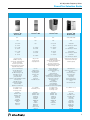
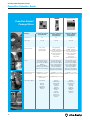
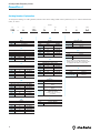
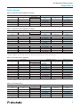
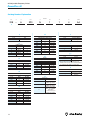
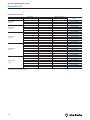
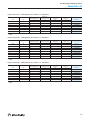
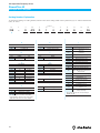
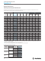
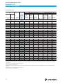
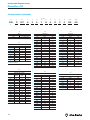
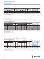
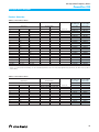
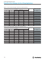
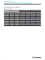
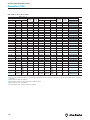
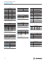
1
For more information on Allen-Bradley drives, please visit our website at: http://www.ab.com/drives PowerFlex® AC Drives Catalog CompactLogix, ControlLogix, DriveExplorer, DriveTools, DriveTools 2000, DriveLogix, FlexLogix, Logix, PowerFlex, ArmorStart, Pocket DriveExplorer, DriveTools SP, DeviceLogix, ArmorPoint, RSLogix 5000, SoftLogix5800, SCANport, SynchLink, FORCE Technology, Zero Stacking, TorqProv, DriveExecutive, DriveObserver, DriveTools32, DriveManager32, DriveMonitor32, DrivePanel32, DriveBlockEditor32, DriveTrending32, DriveManager, DriveMonitor, DrivePanel, DriveBlockEditor,1336 Force, 1336 IMPACT, SMC Dialog Plus, 160 SSC, SMP-3, DriveTrending, DPI, DSI, etc. are trademarks of Rockwell Automation. Trademarks not belonging to Rockwell Automation are property of their respective companies. www.rockwellautomation.com Corporate Headquarters Rockwell Automation, 777 East Wisconsin Avenue, Suite 1400, Milwaukee, WI, 53202-5302 USA, Tel: (1) 414.212.5200, Fax: (1) 414.212.5201 Headquarters for Allen-Bradley Products, Rockwell Software Products and Global Manufacturing Solutions Americas: Rockwell Automation, 1201 South Second Street, Milwaukee, WI 53204-2496 USA, Tel: (1) 414.382.2000, Fax: (1) 414.382.4444 Europe/Middle East/Africa: Rockwell Automation SA/NV, Vorstlaan/Boulevard du Souverain 36, 1170 Brussels, Belgium, Tel: (32) 2 663 0600, Fax: (32) 2 663 0640 Asia Pacific: Rockwell Automation, 27/F Citicorp Centre, 18 Whitfield Road, Causeway Bay, Hong Kong, Tel: (852) 2887 4788, Fax: (852) 2508 1846 Headquarters for Dodge and Reliance Electric Products Americas: Rockwell Automation, 6040 Ponders Court, Greenville, SC 29615-4617 USA, Tel: (1) 864.297.4800, Fax: (1) 864.281.2433 Europe/Middle East/Africa: Rockwell Automation, Brühlstraße 22, D-74834 Elztal-Dallau, Germany, Tel: (49) 6261 9410, Fax: (49) 6261 17741 Asia Pacific: Rockwell Automation, 55 Newton Road, #11-01/02 Revenue House, Singapore 307987, Tel: (65) 6356-9077, Fax: (65) 6356-9011 U.S. Allen-Bradley Drives Technical Support Tel: (1) 262.512.8176, Fax: (1) 262.512.2222, Email: [email protected], Online: www.ab.com/support/abdrives Publication D115-CA001B-EN-P – May 2005 Supersedes D115-CA001A-EN-P – May 2004 Copyright © 2005 Rockwell Automation. All rights reserved. Printed in USA PowerFlex® Family of AC Drives Catalog AC Adjustable Frequency Drives Table of Contents PowerFlex Selection Guide page 4 PowerFlex 4 AC Drives page 7 PowerFlex 40 AC Drives page 13 PowerFlex 40 AC Packaged Drives page 21 ArmorStart page 27 PowerFlex 400 AC Drives page 31 PowerFlex 400 AC Packaged Drives page 39 PowerFlex 70 AC Drives page 45 PowerFlex 70 AC Packaged Drives page 63 PowerFlex 700 AC Drives page 75 PowerFlex 700 AC Packaged Drives page 91 PowerFlex 70/700 Fan and Pump Packages page 103 PowerFlex 700H AC Drives page 115 PowerFlex 700S AC Drives page 123 PowerFlex 7000 Medium Voltage Drives page 147 Drive Software page 149 Technical Services and Support page 153 Important Safety and Product Information page 155 1 AC Adjustable Frequency Drives PowerFlex Family of Drives Powerful Performance. Flexible Control. For motor control applications from low to medium voltage, and from simple to complex, the Powerflex family of drives from 0.2 kW (0.25 Hp) to 6340 kW (8500 Hp) offers world-class motor control solutions. Motor Control Performance Because you have a wide range of control needs, PowerFlex offers a variety of motor control technologies, from Volts/Hertz Control for the simplest applications, to Vector Control with patented FORCE™ Technology, which provides excellent low speed/zero speed performance for both induction and permanent magnet motors. Compact, Space Saving Design The PowerFlex family offers a compact, Zero-Stacking™ design, allowing side by side mounting to optimize panel space. With a variety of enclosure and package options, PowerFlex drives are able to meet your specific application requirements. Advanced Communications Capabilities To help you gain the most from your automation investment, PowerFlex drives utilize an open network architecture to integrate your manufacturing process from shop floor to top floor. PowerFlex drives provide common features and services for DeviceNet™, ControlNet™ and EtherNet™/IP networks, as well as supporting PROFIBUS™, InterBus™, Universal Remote I/O and RS485 DF1. Common Operator Interface and Programming Featuring an advanced, common operator interface, PowerFlex drives reduce training and simplify operation. With a consistent programming structure, common PC tools (for programming, monitoring and troubleshooting), consistent parameter names and descriptions, PowerFlex drives reduce set-up time and costs. Choice, Value and Support And because the PowerFlex family is from Rockwell Automation, you can be sure these world-class solutions come backed by worldleading service and support, maximizing your automation investment now and in the future. 2 AC Adjustable Frequency Drives PowerFlex Family of Drives 3 AC Adjustable Frequency Drives PowerFlex Selection Guide PowerFlex Selection Guide PowerFlex AC Drives Comparison Chart Attributes PowerFlex® 4 PowerFlex® 400 For Fans and Pumps PowerFlex® 70 Enhanced Control Catalog Reference 22A … 22B … 22C … 20A … Ratings 100-120V 0.2 - 1.1 kW 0.25 - 1.5 HP 0.4 - 1.1 kW 0.5 - 1.5 HP N/A N/A Ratings 200-240V 0.2 - 3.7 kW 0.25 - 5 HP 0.4 - 7.5 kW 0.5 - 10 HP 2.2 - 37 kW 3.0 - 50 HP 0.37 - 18.5 kW 0.5 - 25 HP Ratings 400-480V 0.4 - 3.7 kW 0.5 - 5 HP 0.4 - 11 kW 0.5 - 15 HP 2.2 - 110 kW 3.0 - 150 HP 0.37 - 37 kW 0.5 - 50 HP Ratings 500-600V N/A 0.75 - 11 kW 1 - 15 HP N/A 0.37 - 37 kW 0.5 - 50 HP Ratings 690V N/A N/A N/A N/A Volts per Hertz Slip Compensation Volts per Hertz Sensorless Vector Slip Compensation Volts per Hertz Slip Compensation Vector Control (VC) w/FORCE™ Technology Sensorless VC, Slip Compensation Encoder Speed Control Encoderless Speed Control Torque Regulation, Volts per Hertz Drive Overload (OL) Protection Ramp Regulation Flying Start Drive OL Protection Ramp Regulation Standard PID Control Flying Start StepLogic™ Drive OL Protection Ramp Regulation Standard PID Control Flying Start Hand/Off/Auto Sleep-Wake Purge Input Damper Input User Sets, Multi-Language Adv. Drive OL Protection Adv. Bus Regulation Adv. PID Control (Spd or Trq) Droop Analog Trim/Invert Adv. Flying Start Motor OL Protection DriveGuard™ Safe-Off Flux Braking Ambient Temperature Limit for Enclosure Types IP 20/Open = 50°C IP 30/NEMA 1 = 40°C Flange = 50°C IP 20/Open = 50°C IP 30/NEMA 1 = 40°C Flange = 50°C IP 30/NEMA 1 = 45°C NEMA 1/IP 20/Open = 50°C Flange = 50°C NEMA 4X/12, IP 66 = 40°C Communications Options Integral RS485 Integral RS485 Integral RS485 ® w/ Modbus RTU and Metasys N2, Optional: *DeviceNet™ *EtherNet/IP™ *PROFIBUS DP™ Bluetooth® Optional: DeviceNet EtherNet/IP PROFIBUS DP Bluetooth DeviceNet ControlNet™ - Coax ControlNet - Fiber EtherNet/IP Remote I/O RS485 DF1 PROFIBUS DP Interbus™ LonWorks® Modbus RTU Metasys N2 Siemens P1 FLN Bluetooth Control Performance Features * Optional network for use only with External DSI Communications Kit 4 PowerFlex® 40 Optional: DeviceNet EtherNet/IP PROFIBUS DP Bluetooth AC Adjustable Frequency Drives PowerFlex Selection Guide PowerFlex® 700 Vector Control PowerFlex® 700H PowerFlex® 700S PowerFlex® 7000 Medium Voltage 20B … 20C … 20D … 7000A, 7000B, 7000C N/A N/A N/A N/A 0.37 - 55 kW 0.5 - 100 HP N/A 0.75 - 55 kW 1 - 100 HP 2400V 60Hz 150 - 1500 kW, 200 - 2000 HP 0.37 - 132 kW 0.5 - 200 HP 132 - 560 kW 200 - 900 HP 0.75 - 800 kW 1 - 1250 HP 3300V 50Hz 187 - 2050 kW, 250 - 2750 HP 0.75 - 110 kW 1 - 150 HP 110 - 560 kW 150 - 800 HP 50 - 800 kW 1 - 1100 HP 4160V 50/60Hz 260 - 3730 kW, 350 - 5000 HP 45 - 132 kW 160 - 800 kW 75 - 1200 kW 6600V 50Hz 400 - 6340 kW, 500 - 8500 HP Vector Control (VC) w/FORCE™ Technology Sensorless VC, Slip Compensation Encoder Speed Control Encoderless Speed Control Torque Regulation, Volts per Hertz Adjustable Voltage Control Volts per Hertz Sensorless Vector Slip Compensation Vector Control (VC) w/FORCE Technology Sensorless VC, Slip Compensation Encoder Speed Control Encoderless Speed Control Torque Regulation, Volts per Hertz Permanent Magnet Control Digital Sensorless Direct Vector Full Vector Control with Tach Feedback (optional) User Sets, Multi-Language Adv. Drive OL Protection Adv. Bus Regulation Adv. PID Control (Spd or Trq) Flux Braking, Fast Stop Scale Blocks, Droop Analog Trim/Invert TorqProve™, Position Indexing/Speed Profiler Adv. Flying Start Motor OL Protection Common Bus Capability Parameter Linking Open Motor Lead Detection User Sets Multi-Language Drive OL Protection Bus Regulation PI Control Speed Droop Analog Trim Flying Start Motor OL Protection IP 20 / Open = 50°C IP 21/NEMA 1 = 40°C IP 54 Flange = 40°C IP 21 / NEMA 1 Normal Duty = 40°C IP 20 / Open = 50°C IP 21/NEMA 1 = 40°C IP 54 Flange = 40°C IP 21/NEMA 1 = 40° C DeviceNet ControlNet - Coax ControlNet - Fiber EtherNet/IP Remote I/O RS485 DF1 PROFIBUS DP Interbus Modbus RTU Bluetooth DeviceNet ControlNet - Coax ControlNet - Fiber EtherNet/IP Remote I/O RS485 DF1 PROFIBUS DP Interbus LonWorks Modbus RTU Metasys N2 Siemens P1 FLN Bluetooth DeviceNet ControlNet - Coax ControlNet - Fiber EtherNet/IP Remote I/O RS485 DF1 PROFIBUS DP Interbus Modbus RTU Bluetooth Internal - DPI DeviceNet ControlNet - Coax ControlNet - Fiber EtherNet/IP Remote I/O RS485 DF1 RS485 HVAC Modbus RTU Modbus Plus PROFIBUS DP RS232 DFI Bluetooth Adv. Drive OL Protection Adv. Bus Regulation Adv. PI Control (Spd or Trq) Droop Analog Trim/Invert Feedback Loss Switchover Stegmann Interface, Heidenhain Interface Resolver Interface, Stahltronic and Temposonics SSI Interface Integral Position Loop SynchLink™ DriveLogix™ Option Inertia Adaptation User Function Blocks Motor Overload Common Bus Capability 6.5KV SGCT Power Semiconductor with Integrated Gate Drive Patented PowerCage™ Converter Modules Set-up Wizard Auto Tuning Remote "Dial-In" Access Field Programmable Gate Arrays Drive Identity Module 5 AC Adjustable Frequency Drives PowerFlex Selection Guide PowerFlex Standard Packaged Drives PowerFlex® 40 Standard Packaged Drive PowerFlex® 70 Enhanced Control Standard Packaged Drive PowerFlex® 700 Vector Control Standard Packaged Drive 23B 21A 21B 0.5-15 HP 0.5-50 HP 0.5-200 HP Volts per Hertz Sensorless Vector Slip Compensation Vector Control (VC) w/FORCE™ Technology Sensorless VC, Slip Compensation Encoder Speed Control Encoderless Speed Control Torque Regulation Volts per Hertz Vector Control (VC) w/FORCE™ Technology Sensorless VC, Slip Compensation Encoder Speed Control Encoderless Speed Control Torque Regulation Volts per Hertz Adjustable Voltage Control Features All Standard Drive Features Power Disconnect Options Control and Interface Options I/O Options Quick Disconnect Options Program Specific Documentation Additional Custom Capabilities All Standard Drive Features Power Disconnect Options Control and Interface Options Bypass and Bypass Options Power Conditioning Options Motor Interface Options Order Specific Documentation Additional Custom Capabilities All Standard Drive Features Power Disconnect Options Control and Interface Options Bypass and Bypass Options Power Conditioning Options Motor Interface Options Order Specific Documentation Additional Custom Capabilities Ambient Temperature Limit for Enclosure Types IP 20/NEMA 1 = 0° to 40°C IP 20/NEMA 1 = 0° to 40°C IP 66/NEMA 4/12 = 0° to 40°C IP 65/NEMA 4/12 (indoor) = 0° to 40°C IP 54/NEMA 12 Fan & Filter = 0° to 40°C (NEMA 4 indoor/outdoor) Attributes Catalog Reference Ratings 480V Control Performance Communications Options IP 66/NEMA 4X = 0° to 40°C (indoor/outdoor) IP 65/NEMA 4 (outdoor) = 0° to 40°C Integral RS485 DeviceNet ControlNet-Coax ControlNet-Fiber EtherNet/IP Remote I/O RS485 DF1 PROFIBUS DP Interbus LonWorks Modbus RTU Metasys N2 Siemens P1 FLN Bluetooth Optional: DeviceNet EtherNet/IP PROFIBUS DP Bluetooth 6 DeviceNet ControlNet-Coax ControlNet-Fiber EtherNet/IP Remote I/O RS485 DF1 PROFIBUS DP Interbus Modbus RTU Bluetooth AC Adjustable Frequency Drives PowerFlex 4 PowerFlex 4 AC Drive Drive Description Contents Standard Product Description this page Conformity to Standards this page Catalog Number Explanation page 8 Product Selection page 9 User Installed Options page 10 PowerFlex® 4 drives are designed to worldwide standards and ratings, allowing out-of-the-box performance around the globe. Drives are available in two frame sizes that cover ratings from 0.2 to 3.7 kW (0.25 to 5 Hp), 100 to 120 volts, 200 to 240 volts and 380 to 480 volts. Drives feature integral RS485 communications and are compatible with PC tools such as DriveExplorer™ and DriveTools™ SP which assist with programming, monitoring, and troubleshooting PowerFlex drives. Conformity to Standards PowerFlex 4 drives conform to the following: Conformity to: Standard Product UL Listed ! IEC (Designed to Meet) ! CE Approved ! C-Tick ! 7 AC Adjustable Frequency Drives PowerFlex 4 Catalog Number Explanation To interpret the meaning of a catalog number, match the values of the catalog number code in positions a, b, c, etc. with the tables labeled a, b, c, etc. below. Position 1-3 4 5 6-8 9 10 11 12 13-14 22A – A 1P5 N 1 1 4 AA b c d e f g h a a c4 f Drive Rating Emission Class Code Type 22A PowerFlex 4 200-240V Three-Phase Input b Voltage Rating Code Voltage Ph. V 120V ac 1 A 240V ac 1 B 240V ac 3 D 480V ac 3 Code Rating Code Amps kW (Hp) 0 Not Filtered 1P5 1.5 0.2 (0.25) 1 Filtered 2P3 2.3 0.4 (0.5) 4P5 4.5 0.75 (1.0) 8P0 8.0 1.5 (2.0) 012 12.0 2.2 (3.0) 017 17.5 3.7 (5.0) c5 380-480V Three-Phase Input Rating 100-120V Single-Phase Input Code Amps kW (Hp) 1P5 1.5 0.2 (0.25) 2P3 2.3 0.4 (0.5) 4P5 4.5 0.75 (1.0) 6P0 6.0 1.1 (1.5) Amps kW (Hp) 1P4 1.4 0.2 (0.25) 2P1 2.1 0.4 (0.5) 3P6 3.6 0.75 (1.0) 6P8 6.8 1.5 (2.0) 9P6 9.6 2.2 (3.0) 0.4 (0.5) 2.3 0.75 (1.0) h 4P0 4.0 1.5 (2.0) Optional 6P0 6.0 2.2 (3.0) 8P7 8.7 3.7 (5.0) Code Enclosure N Panel Mount - IP 20 (NEMA Type Open) F Flange Mount - IP 20 (NEMA Type Open) H Replacement Plate Drive - IP 20 (NEMA Type Open) - Contact factory for ordering information. Rating 8 kW (Hp) 1P5 1.5 0.2 (0.25) 2P3 2.3 0.4 (0.5) 4P5 4.5 0.75 (1.0) 8P0 8.0 1.5 (2.0) indicates drive version. All PowerFlex 4 drives are equipped with RS485 communication. 2P3 e Amps Standard kW (Hp) HIM Code 4 1.4 c3 200-240V Single-Phase Input No Brake IGBT Amps c2 Code Version 3 1P4 d 200-240V Single-Phase Input - No Brake Code Code Enclosure Rating ✶ ✶ This position of the Catalog Number now Rating c1 g Version Code Interface Module 1 Fixed Keypad Code Purpose AA through ZZ Reserved for custom firmware AC Adjustable Frequency Drives PowerFlex 4 Product Selection 120V ac, Single-Phase Drives (50/60 Hz, No Filter) Drive Ratings IP20/NEMA Type Open IP20 Flange Mount✶ Output Current kW 0.2 Hp 0.25 A Cat. No. Frame Size Cat. No. 1.5 22A-V1P5N104 A 22A-V1P5F104 0.4 0.5 2.3 22A-V2P3N104 A 22A-V2P3F104 0.75 1.0 4.5 22A-V4P5N104 B 22A-V4P5F104 1.1 1.5 6.0 22A-V6P0N104 B 22A-V6P0F104 ✶ Meets IP40/54/65 (NEMA 1/12/4/4X) when installed in an enclosure of like rating. 240V ac, Single-Phase Drives (50/60 Hz, No Brake) Drive Ratings IP20/NEMA Type Open IP20 Flange Mount✶ Output Current kW Hp A Cat. No. Frame Size Cat. No. With Integral "S Type" EMC Filter" 0.2 0.25 1.4 22A-A1P4N113 A – 0.4 0.5 2.1 22A-A2P1N113 A – 0.75 1.0 3.6 22A-A3P6N113 A – 1.5 2.0 6.8 22A-A6P8N113 B – 2.2 3.0 9.6 22A-A9P6N113 B – No Filter 0.2 0.25 1.4 22A-A1P4N103 A – 0.4 0.5 2.1 22A-A2P1N103 A – 0.75 1.0 3.6 22A-A3P6N103 A – 1.5 2.0 6.8 22A-A6P8N103 B – 2.2 3.0 9.6 22A-A9P6N103 B – ✶ Meets IP40/54/65 (NEMA 1/12/4/4X) when installed in an enclosure of like rating. " This filter is suitable for use with a cable length of up to 10 meters for Class A and 1 meter for Class B environments. 240V ac, Three-Phase Drives (50/60 Hz) Drive Ratings IP20/NEMA Type Open IP20 Flange Mount✶ Output Current kW Hp A Cat. No. Frame Size Cat. No. With Integral "S Type" EMC Filter" 0.2 0.25 1.5 22A-A1P5N114 A – 0.4 0.5 2.3 22A-A2P3N114 A – 0.75 1.0 4.5 22A-A4P5N114 A – 1.5 2.0 8.0 22A-A8P0N114 B – No Filter 0.2 0.25 1.5 22A-A1P5N104 A 22A-A1P5F104 0.4 0.5 2.3 22A-A2P3N104 A 22A-A2P3F104 0.75 1.0 4.5 22A-A4P5N104 A 22A-A4P5F104 1.5 2.0 8.0 22A-A8P0N104 B 22A-A8P0F104 ✶ Meets IP40/54/65 (NEMA 1/12/4/4X) when installed in an enclosure of like rating. " This filter is suitable for use with a cable length of up to 10 meters for Class A and 1 meter for Class B environments. 480V ac, Three-Phase Drives Drive Ratings IP20/NEMA Type Open IP20 Flange Mount✶ Output Current kW Hp A Cat. No. Frame Size Cat. No. 0.4 0.5 1.4 22A-D1P4N104 A 22A-D1P4F104 0.75 1.0 2.3 22A-D2P3N104 A 22A-D2P3F104 1.5 2.0 4.0 22A-D4P0N104 A 22A-D4P0F104 2.2 3.0 6.0 22A-D6P0N104 B 22A-D6P0F104 3.7 5.0 8.7 22A-D8P7N104 B 22A-D8P7F104 ✶ Meets IP40/54/65 (NEMA 1/12/4/4X) when installed in an enclosure of like rating. 9 AC Adjustable Frequency Drives PowerFlex 4 User Installed Options IP30/NEMA 1/UL Type 1 Conversion Kit Description Field installed kit. Converts drive to IP30/NEMA 1/UL Type 1 enclosure. Includes conduit box with mounting screws and plastic top panel. Communication Option Kits Drive Frame Description Cat. No. A 22-JBAA B 22-JBAB Human Interface Module Option Kits and Accessories Description Cat. No. LCD Display, Remote Panel Mount, Digital Speed Control, CopyCat capable, IP66 (NEMA Type 4X/12) indoor use only, 22-HIM-C2S✶ Includes 2.0 meter cable. LCD Display, Remote Panel Mount, Digital Speed Control, CopyCat capable, IP66 (NEMA Type 4X/12) indoor use only, Includes 2.9 meter cable. 22-HIM-C2 LCD Display, Remote Handheld, Digital Speed Control, Full Numeric Keypad, CopyCat capable, IP30 (NEMA Type 1), Includes 1.0 meter cable, Panel Mount with optional Bezel Kit. 22-HIM-A3 Remote Handheld, Wireless Interface Module with Bluetooth technology, IP30 (NEMA Type 1), Panel Mount with optional Bezel Kit. 22-WIM-N1 Cat. No. Serial Converter Module (RS485 to RS232) Description: Provides serial communication via DF1 protocol for use with DriveExplorer and DriveExecutive software. Includes: DSI to RS232 serial converter, 1203-SFC serial cable, 22-RJ45CBL-C20 cable, and DriveExplorer Lite CD. 22-SCM-232 Serial Cable Description: 2.0 meter serial cable with a locking low profile connector to connect to the serial converter and a 9-pin sub-miniature D female connector to connect a computer. 1203-SFC Null Cable Converter Description: For use when connecting the serial converter to DriveExplorer on a handheld PC. 1203-SNM DSI Cable Description: 2.0 meter RJ45 to RJ45 cable, male to male connectors. 22-RJ45CBLC20 Splitter Cable Description: RJ45 one to two port splitter cable. AK-U0-RJ45SC1 Terminating Resistors Description:120 Ohm resistor embedded in an RJ45 connector (2 pieces). AK-U0-RJ45TR1 Terminal Block Description: RJ45 two position terminal block (5 pieces) with two 120 Ohm terminating resistors (loose). AK-U0-RJ45TB2P Remote Panel Mount, Wireless Interface Module with Bluetooth technology, IP66 (NEMA Type 4X/12) indoor use only. 22-WIM-N4S Bezel Kit. Panel Mount for LCD Display, Remote Handheld unit, IP30 (NEMA Type 1). Includes a 22-RJ45CBL-C20 cable. 22-HIM-B1 External DSI Communications Kit Description: External mounting kit for 22-COMM-D, -E, and -P. 22-XCOMMDC-BASE 22-HIM-H10 External Comms Power Supply Description: Optional 100…240V ac Power Supply for External DSI Communications Kit 20-XCOMMAC-PS1 DSI HIM Cable (DSI HIM to RJ45 cable) 1.0 Meter (3.3 Feet) 2.9 Meter (9.51 Feet) 22-HIM-H30 ✶ The 22-HIM-C2S is smaller than the 22-HIM-C2 and cannot be used as a direct replacement. EtherNet/IP™ Communication Adapter 22-COMM-E‡ PROFIBUS™ DP Communication Adapter 22-COMM-P‡ Compact I/O Module (3 Channel) Spare Parts Description Cat. No. Fan Replacement Kit - Frame A SK-U1-FAN1-A1 Fan Replacement Kit - Frame B, 1 Fan SK-U1-FAN1-B1 Fan Replacement Kit - Frame B, 2 Fans SK-U1-FAN2-B1 Frame A Cover with Power Terminal Guard SK-U1-ACVR1-A1 Frame B Cover with Power Terminal Guard SK-U1-ACVR1-B1 1769-SM2 " If NEMA 1/IP30 is required, must also order 22-JBCB (Frame B drives) or 22-JBCC (Frame C drives). ‡ PowerFlex 4 drives require External DSI Communication Kits. Communication Adapters cannot be drive mounted. PC Programming Software Description Frame A Cover - Black without Logo SK-U1-CVR2-A1 DriveTools™ SP Software Frame B Cover - Black without Logo SK-U1-CVR2-B1 DriveExplorer™ Software Pocket DriveExplorer™ Software 10 22-COMM-D‡ DeviceNet Communication Adapter See A-B publication 9303-PL002… for ordering/pricing information. AC Adjustable Frequency Drives PowerFlex 4 Input Line Reactors - 240V, 50/60 Hz, Three-Phase, 3% Impedance kW 0.2 Fundamental Amps Maximum Continuous Amps Inductance A A mh Hp 0.25 2.0 3.0 Watts Loss W 12 Cat. No.✶ 7.5 1321-3R2-A 0.4 0.5 4.0 6.0 12 21 1321-3R4-B 0.75 1.0 8.0 12 3.0 29 1321-3R8-B 1.5 2.0 8.0 12 1.5 19.5 1321-3R8-A 2.2 3.0 12 18 1.25 26 1321-3R12-A 3.7 5.0 18 27 0.8 36 1321-3R18-A ✶ Catalog numbers listed are for 3% impedance open style units. NEMA Type 1 and 5% impedance reactor types are also available. Refer to publication 1321- TD001…. Input Line Reactors - 480V, 50/60 Hz, Three-Phase, 3% Impedance kW Fundamental Amps Maximum Continuous Amps Inductance A A mh Hp 0.4 0.5 2.0 3.0 20 Watts Loss W Cat. No.✶ 11.3 1321-3R2-B 1321-3R4-C 0.75 1.0 4.0 6.0 9.0 20 1.5 2.0 4.0 6.0 6.5 20 1321-3R4-B 2.2 3.0 8.0 12 5.0 25.3 1321-3R8-C 3.7 5.0 8.0 12 3.0 29 1321-3R8-B ✶ Catalog numbers listed are for 3% impedance open style units. NEMA Type 1 and 5% impedance reactor types are also available. Refer to publication 1321- TD001…. EMC Filters Drive Ratings 240V 50/60 Hz 1-Phase 240V 50/60 Hz 1-Phase NO BRAKE 240V 50/60 Hz 3-Phase 480V 50/60 Hz 3-Phase L Type Filter Cat. No. ‡ 0.25 – 22-RF010-AL 0.4 0.5 – 22-RF010-AL 0.75 1.0 – 22-RF018-BL kW 0.2 120V 50/60 Hz 1-Phase S Type Filter Cat. No. ✶ Input Voltage Hp 1.1 1.5 – 22-RF025-CL § 0.2 0.25 " 22-RF010-AL 0.4 0.5 " 22-RF010-AL 0.75 1.0 " 22-RF010-AL 1.5 2.0 " 22-RF018-BL 0.2 0.25 " 22-RF010-AL 0.4 0.5 " 22-RF010-AL 0.75 1.0 " 22-RF010-AL 1.5 2.0 " 22-RF018-BL 2.2 3.0 " 22-RF025-CL § 0.2 0.25 22-RF9P5-AS 22-RF9P5-AL 0.4 0.5 22-RF9P5-AS 22-RF9P5-AL 0.75 1.0 22-RF9P5-AS 22-RF9P5-AL 1.5 2.0 22-RF9P5-AS 22-RF9P5-AL 2.2 3.0 22-RF021-BS 22-RF021-BL 3.7 5.0 22-RF021-BS 22-RF021-BL 0.4 0.5 22-RF5P7-AS 22-RF5P7-AL 0.75 1.0 22-RF5P7-AS 22-RF5P7-AL 1.5 2.0 22-RF5P7-AS 22-RF5P7-AL 2.2 3.0 22-RF012-BS 22-RF012-BL 3.7 5.0 22-RF012-BS 22-RF012-BL ✶ This filter is suitable for use with a cable length of up to 10 meters for Class A and 1 meter for Class B environments. " Drives are available in these ratings with internal “S Type” filters. ‡ This filter is suitable for use with a cable length of up to 100 meters for Class A and 5 meters for Class B environments. § The piggyback mounting option cannot be used with Frame B PowerFlex 4 drives and Frame C EMC Line Filters. 11 AC Adjustable Frequency Drives PowerFlex 4 Dynamic Brake Resistors Drive Ratings Input Voltage 0.2 120V 50/60 Hz 1-Phase 240V 50/60 Hz 1-Phase 240V 50/60 Hz 3-Phase 480V 50/60 Hz 3-Phase Ω Hp 0.25 Cat. No.✶ 48 AK-R2-091P500 0.4 0.5 48 AK-R2-091P500 0.75 1.0 48 AK-R2-091P500 0.2 0.25 48 AK-R2-091P500 0.4 0.5 48 AK-R2-091P500 0.75 1.0 48 AK-R2-091P500 1.5 2.0 48 AK-R2-091P500 0.2 0.25 48 AK-R2-091P500 0.4 0.5 48 AK-R2-091P500 0.75 1.0 48 AK-R2-091P500 1.5 2.0 48 AK-R2-091P500 2.2 3.0 32 AK-R2-047P500 3.7 5.0 19 AK-R2-047P500 0.4 0.5 97 AK-R2-360P500 0.75 1.0 97 AK-R2-360P500 1.5 2.0 97 AK-R2-360P500 2.2 3.0 97 AK-R2-120P1K2 3.7 5.0 77 AK-R2-120P1K2 ✶ Resistors listed in this table are rated 5% duty cycle. 12 Minimum Resistance kW AC Adjustable Frequency Drives PowerFlex 40 PowerFlex 40 AC Drive Drive Description Contents Standard Product Packaged Product Conformity to Standards this page page 24 Description this page page 21 Catalog Number Explanation page 14 page 22 Product Selection page 15 page 23 User Installed Options page 17 Factory Installed Options page 23 PowerFlex® 40 drives are designed to worldwide standards and ratings, allowing out-of-the-box performance around the globe. Drives are available in two frame sizes that cover ratings from 0.4 to 11 kW (0.5 to 15 Hp), 100 to 120 volts, 200 to 240 volts, 380 to 480 volts and 460 to 600 volts. Drives feature integral RS485 communications and are compatible with PC tools such as DriveExplorer™ and DriveTools™ SP which assist with programming, monitoring, and troubleshooting PowerFlex drives. Conformity to Standards PowerFlex 40 drives conform to the following: Conformity to: Standard Product UL Listed 9 IEC (Designed to Meet) 9 CE Approved 9 C-Tick 9 13 AC Adjustable Frequency Drives PowerFlex 40 Catalog Number Explanation Position 1-3 4 5 6-8 9 10 11 12 13-14 22B – A 2P3 N 1 1 4 AA b c d e f g h a a c4 e Drive Rating HIM Code Type 22B PowerFlex 40 380-480V Three-Phase Input b Voltage Rating Code Voltage Ph. V 120V ac 1 A 240V ac 1 B 240V ac 3 D 480V ac 3 E 600V ac 3 Code Amps kW (Hp) 1P4 1.4 0.4 (0.5) 2P3 2.3 0.75 (1.0) 4P0 4.0 1.5 (2.0) 6P0 6.0 2.2 (3.0) 010 10.5 4.0 (5.0) 012 12 5.5 (7.5) 017 17 7.5 (10) 024 24 11 (15) c5 460-600V Three-Phase Input Rating 100-120V Single-Phase Input Code Amps kW (Hp) 2P3 2.3 0.4 (0.5) 5P0 5.0 0.75 (1.0) 6P0 6.0 1.1 (1.5) c2 14 0.4 (0.5) 5.0 0.75 (1.0) 8P0 8.0 1.5 (2.0) 012 12 2.2 (3.0) 017 17.5 3.7 (5.0) 024 24 5.5 (7.5) 033 33 7.5 (10) Standard 2.2 (3.0) 4.0 (5.0) h 9P9 9.9 5.5 (7.5) Optional 012 12 7.5 (10) 019 19 11 (15) Code Enclosure N Panel Mount - IP 20 (NEMA Type Open) F Flange Mount - IP 20 (NEMA Type Open) H Replacement Plate Drive - IP 20 (NEMA Type Open) - Contact factory for ordering information. c3 5P0 4 6.6 0.75 (1.0) kW (Hp) No Brake IGBT 4.2 5.0 2.3 Version 3 6P6 5P0 Amps Code 4P2 d 2P3 ✶ 1.5 (2.0) Enclosure Code g 0.75 (1.0) 0.4 (0.5) 200-240V Three-Phase Input Filtered 3.0 kW (Hp) Rating 1 1.7 2.3 2.2 (3.0) Not Filtered 3P0 Amps 1.5 (2.0) Rating 0 1P7 2P3 12 Code kW (Hp) 200-240V Single-Phase Input 8.0 f Emission Class Amps Code 012 Fixed Keypad Code Rating 8P0 Interface Module 1 Version Rating c1 Code ✶ This position of the Catalog Number now indicates drive version. All PowerFlex 40 drives are equipped with RS485 communication. Code Purpose AA through ZZ Reserved for custom firmware AC Adjustable Frequency Drives PowerFlex 40 Product Selection 120V ac, Single-Phase Drives (50/60 Hz, No Filter) Drive Ratings IP20/NEMA Type Open IP20 Flange Mount✶ Output Current kW Hp A Cat. No. Frame Size Cat. No. 0.4 0.5 2.3 22B-V2P3N104 B 22B-V2P3F104 0.75 1.0 5.0 22B-V5P0N104 B 22B-V5P0F104 1.1 1.5 6.0 22B-V6P0N104 B 22B-V6P0F104 ✶ Meets IP40/54/65 (NEMA 1/12/4/4X) when installed in an enclosure of like rating. 240V ac, Single-Phase Drives (50/60 Hz) Drive Ratings IP20/NEMA Type Open IP20 Flange Mount✶ Output Current kW Hp A Cat. No. Frame Size Cat. No. With Integral “S Type” EMC Filter7 0.4 0.5 2.3 22B-A2P3N114 B – 0.75 1.0 5.0 22B-A5P0N114 B – 1.5 2.0 8.0 22B-A8P0N114 B – 2.2 3.0 12 22B-A012N114 C – No Filter 0.4 0.5 2.3 22B-A2P3N104 B 22B-A2P3F104 0.75 1.0 5.0 22B-A5P0N104 B 22B-A5P0F104 1.5 2.0 8.0 22B-A8P0N104 B 22B-A8P0F104 2.2 3.0 12 22B-A012N104 C 22B-A012F104 ✶ Meets IP40/54/65 (NEMA 1/12/4/4X) when installed in an enclosure of like rating. 7 This filter is suitable for use with a cable length of up to 10 meters for Class A and 1 meter for Class B environments. 240V ac, Three-Phase Drives (50/60 Hz, No Filter) Drive Ratings IP20/NEMA Type Open IP20 Flange Mount✶ Output Current kW Hp A Cat. No. Frame Size Cat. No. 0.4 0.5 2.3 22B-B2P3N104 B 22B-B2P3F104 0.75 1.0 5.0 22B-B5P0N104 B 22B-B5P0F104 1.5 2.0 8.0 22B-B8P0N104 B 22B-B8P0F104 2.2 3.0 12 22B-B012N104 B 22B-B012F104 3.7 5.0 17.5 22B-B017N104 B 22B-B017F104 5.5 7.5 24 22B-B024N104 C 22B-B024F104 7.5 10 33 22B-B033N104 C 22B-B033F104 ✶ Meets IP40/54/65 (NEMA 1/12/4/4X) when installed in an enclosure of like rating. 15 AC Adjustable Frequency Drives PowerFlex 40 480V ac, Three-Phase Drives (50/60 Hz, No Filter) Drive Ratings IP20/NEMA Type Open IP20 Flange Mount✶ Output Current kW Hp A Cat. No. Frame Size Cat. No. 0.4 0.5 1.4 22B-D1P4N104 B 22B-D1P4F104 0.75 1.0 2.3 22B-D2P3N104 B 22B-D2P3F104 1.5 2.0 4.0 22B-D4P0N104 B 22B-D4P0F104 2.2 3.0 6.0 22B-D6P0N104 B 22B-D6P0F104 4.0 5.0 10.5 22B-D010N104 B 22B-D010F104 5.5 7.5 12 22B-D012N104 C 22B-D012F104 7.5 10 17 22B-D017N104 C 22B-D017F104 11 15 24 22B-D024N104 C 22B-D024F104‡ ✶ Meets IP40/54/65 (NEMA 1/12/4/4X) when installed in an enclosure of like rating. ‡ Requires use of external DC Bus inductor or AC Line Reactor. 600V ac, Three-Phase Drives (50/60 Hz, No Filter) Drive Ratings IP20/NEMA Type Open IP20 Flange Mount✶ Output Current kW Hp A Cat. No. Frame Size Cat. No. 0.75 1.0 1.7 22B-E1P7N104 B 22B-E1P7F104 1.5 2.0 3.0 22B-E3P0N104 B 22B-E3P0F104 2.2 3.0 4.2 22B-E4P2N104 B 22B-E4P2F104 4.0 5.0 6.6 22B-E6P6N104 B 22B-E6P6F104 5.5 7.5 9.9 22B-E9P9N104 C 22B-E9P9F104 7.5 10 12 22B-E012N104 C 22B-E012F104 11 15 19 22B-E019N104 C 22B-E019F104 ✶ Meets IP40/54/65 (NEMA 1/12/4/4X) when installed in an enclosure of like rating. 16 AC Adjustable Frequency Drives PowerFlex 40 User Installed Options IP30/NEMA 1/UL Type 1 Conversion Kit Description Drive Frame Field installed kit. Converts drive to B IP30/NEMA 1/UL Type 1 enclosure. Includes conduit box with mounting C screws and plastic top panel. Field installed kit. Converts drive to IP30/NEMA 1/UL Type 1 enclosure. Includes communication option conduit box with mounting screws and plastic top panel. Communication Option Kits Cat. No. 22-JBAB 22-JBAC B 22-JBCB C 22-JBCC Human Interface Module Option Kits and Accessories Description Cat. No. Description Cat. No. Serial Converter Module (RS485 to RS232) Description: Provides serial communication via DF1 protocol for use with DriveExplorer and DriveExecutive software. Includes: DSI to RS232 serial converter, 1203-SFC serial cable, 22-RJ45CBL-C20 cable, and DriveExplorer Lite CD. 22-SCM-232 Serial Cable Description: 2.0 meter serial cable with a locking low profile connector to connect to the serial converter and a 9-pin sub-miniature D female connector to connect a computer. 1203-SFC Null Cable Converter Description: For use when connecting the serial converter to DriveExplorer on a handheld PC. 1203-SNM DSI Cable Description: 2.0 meter RJ45 to RJ45 cable, male to male connectors. 22-RJ45CBLC20 LCD Display, Remote Panel Mount, Digital Speed Control, CopyCat capable, IP66 (NEMA Type 4X/12) indoor use only. Includes 2.0 meter cable. 22-HIM-C2S✶ LCD Display, Remote Panel Mount, Digital Speed Control, CopyCat capable, IP66 (NEMA Type 4X/12) indoor use only. Includes 2.9 meter cable. 22-HIM-C2 Splitter Cable Description: RJ45 one to two port splitter cable. AK-U0-RJ45SC1 LCD Display, Remote Handheld, Digital Speed Control, Full Numeric Keypad, CopyCat capable, IP30 (NEMA Type 1). Includes 1.0 meter cable, Panel Mount with optional Bezel Kit. 22-HIM-A3 Terminating Resistors Description:120 Ohm resistor embedded in an RJ45 connector (2 pieces). AK-U0-RJ45TR1 Remote Handheld, Wireless Interface Module with Bluetooth technology, IP30 (NEMA Type 1), Panel Mount with optional Bezel Kit. AK-U0-RJ45TB2P 22-WIM-N1 Terminal Block Description: RJ45 two position terminal block (5 pieces) with two 120 Ohm terminating resistors (loose). DeviceNet Communication Adapter Note: Requires a Communication Adapter Cover when used with Frame B and C PowerFlex 40 drives (Ordered Separately). 22-COMM-D 22-HIM-B1 EtherNet/IP™ Communication Adapter Note: Requires a Communication Adapter Cover when used with Frame B and C PowerFlex 40 drives (Ordered Separately). 22-COMM-E 22-HIM-H10 PROFIBUS™ DP Communication Adapter Note: Requires a Communication Adapter Cover when used with Frame B and C PowerFlex 40 drives (Ordered Separately). 22-COMM-P External DSI Communications Kit Description: External mounting kit for 22-COMM-D, -E, and -P. 22-XCOMMDC-BASE External Comms Power Supply Description: Optional 100…240V ac Power Supply for External DSI Communications Kit 20-XCOMMAC-PS1 Remote Panel Mount, Wireless Interface Module with Bluetooth technology, IP66 (NEMA Type 4X/12) indoor use only. Bezel Kit. Panel Mount for LCD Display, Remote Handheld unit, IP30 (NEMA Type 1). Includes a 22RJ45CBL-C20 cable. DSI HIM Cable (DSI HIM to RJ45 cable) 1.0 Meter (3.3 Feet) 2.9 Meter (9.51 Feet) 22-WIM-N4S 22-HIM-H30 ✶ The 22-HIM-C2S is smaller than the 22-HIM-C2 and cannot be used as a direct replacement. Spare Parts Description Cat. No. Fan Replacement Kit - Frame B, 1 Fan SK-U1-FAN1-B1 Compact I/O Module (3 Channel) Fan Replacement Kit - Frame B, 2 Fans SK-U1-FAN2-B1 Fan Replacement Kit - Frame C, 1 Fan SK-U1-FAN1-C1 Communication Adapter Cover Description: Houses the Communication Adapter for Frame B and C drives. Note: This cover adds 25 mm (0.98 in.) to the overall depth of the drive. Fan Replacement Kit - Frame C, 1 Fan, 15 Hp SK-U1-FAN1-C2 1769-SM2 Frame B Cover with Power Terminal Guard SK-U1-BCVR1-B1 Frame C Cover with Power Terminal Guard SK-U1-BCVR1-C1 Frame B Drive 22B-CCB7 SK-U1-CVR2-B1 Frame C Drive 22B-CCC7 7 If NEMA 1/IP30 is required, must also order 22-JBCB (Frame B drives) or 22-JBCC (Frame C drives). Frame B Cover - Black without Logo Frame C Cover - Black without Logo SK-U1-CVR2-C1 Frame B Cover for Comm Option - Black without Logo SK-U1-CVR2-BC Frame C Cover for Comm Option - Black without Logo SK-U1-CVR2-CC PC Programming Software Description DriveTools™ SP Software DriveExplorer™ Software See A-B publication 9303-PL002… for ordering/pricing information. Pocket DriveExplorer™ Software 17 AC Adjustable Frequency Drives PowerFlex 40 Dynamic Brake Resistors Drive Ratings Input Voltage 120V 50/60 Hz 1-Phase 240V 50/60 Hz 1-Phase 240V 50/60 Hz 3-Phase 480V 50/60 Hz 3-Phase 600V 50/60 Hz 3-Phase Ω Hp Cat. No.✶ 0.4 0.5 48 AK-R2-091P500 0.75 1.0 48 AK-R2-091P500 1.1 1.5 48 AK-R2-091P500 0.4 0.5 48 AK-R2-091P500 0.75 1.0 48 AK-R2-091P500 1.5 2.0 48 AK-R2-091P500 2.2 3.0 32 AK-R2-047P500 0.4 0.5 48 AK-R2-091P500 0.75 1.0 48 AK-R2-091P500 1.5 2.0 48 AK-R2-091P500 2.2 3.0 32 AK-R2-047P500 3.7 5.0 19 AK-R2-047P500 5.5 7.5 13 AK-R2-030P1K2 7.5 10 10 AK-R2-030P1K2 0.4 0.5 97 AK-R2-360P500 0.75 1.0 97 AK-R2-360P500 1.5 2.0 97 AK-R2-360P500 2.2 3.0 97 AK-R2-120P1K2 4.0 5.0 77 AK-R2-120P1K2 5.5 7.5 55 AK-R2-120P1K2 7.5 10 39 AK-R2-120P1K2 11 15 24 AK-R2-120P1K2 7 AK-R2-360P500 0.75 1.0 120 1.5 2.0 120 AK-R2-360P500 2.2 3.0 82 AK-R2-120P1K2 4.0 5.0 82 AK-R2-120P1K2 5.5 7.5 51 AK-R2-120P1K2 7.5 10 51 AK-R2-120P1K2 11 15 51 AK-R2-120P1K2 7 ✶ Resistors listed in this table are rated 5% duty cycle. 7 Requires two resistors wired in parallel. 18 Minimum Resistance kW AC Adjustable Frequency Drives PowerFlex 40 Input Line Reactors - 240V, 50/60 Hz, Three-Phase, 3% Impedance kW Fundamental Amps Maximum Continuous Amps Inductance A A mh Hp Watts Loss W Cat. No.✶ 0.4 0.5 4.0 6.0 12 21 1321-3R4-B 0.75 1.0 8.0 12 3.0 29 1321-3R4-B 1.5 2.0 8.0 12 1.5 19.5 1321-3R8-B 2.2 3.0 12 18 1.25 26 1321-3R12-A 3.7 5.0 18 27 0.8 36 1321-3R18-A 5.5 7.5 25 37.5 0.5 48 1321-3R25-A 7.5 10 35 52.5 0.4 49 1321-3R35-A ✶ Catalog numbers listed are for 3% impedance open style units. NEMA Type 1 and 5% impedance reactor types are also available. Refer to publication 1321- TD001…. Input Line Reactors - 480V, 50/60 Hz, Three-Phase, 3% Impedance kW Fundamental Amps Maximum Continuous Amps Inductance A A mh Hp Watts Loss W Cat. No.✶ 0.4 0.5 2.0 3.0 20 11.3 1321-3R2-B 1321-3R4-C 0.75 1.0 4.0 6.0 9.0 20 1.5 2.0 4.0 6.0 6.5 20 1321-3R4-B 2.2 3.0 8.0 12 5.0 25.3 1321-3R8-C 4.0 5.0 12 18 2.5 31 1321-3R8-B 5.5 7.5 12 18 2.5 31 1321-3R12-B 7.5 10 18 27 1.5 43 1321-3R18-B 11 15 25 37.5 1.2 52 1321-3R25-B ✶ Catalog numbers listed are for 3% impedance open style units. NEMA Type 1 and 5% impedance reactor types are also available. Refer to publication 1321- TD001…. Input Line Reactors - 600V, 50/60 Hz, Three-Phase, 3% Impedance kW 0.75 Fundamental Amps Maximum Continuous Amps Inductance A A mh Hp 1.0 2.0 3.0 20 Watts Loss W Cat. No.✶ 11.3 1321-3R2-B 1321-3R4-C 1.5 2.0 4.0 6.0 6.5 20 2.2 3.0 4.0 6.0 6.5 20 1321-3R4-B 4.0 5.0 8.0 12 5.0 25.3 1321-3R8-C 5.5 7.5 12 18 2.5 31 1321-3R12-B 7.5 10 12 18 2.5 31 1321-3R12-B 11 15 18 27 1.5 43 1321-3R18-B ✶ Catalog numbers listed are for 3% impedance open style units. NEMA Type 1 and 5% impedance reactor types are also available. Refer to publication 1321- TD001…. 19 AC Adjustable Frequency Drives PowerFlex 40 EMC Filters Drive Ratings Input Voltage 120V 50/60 Hz 1-Phase 240V 50/60 Hz 1-Phase 240V 50/60 Hz 3-Phase 480V 50/60 Hz 3-Phase 600V 50/60 Hz 3-Phase S Type Filter kW Hp Cat. No.§ 0.4 0.5 – 22-RF018-BL 0.75 1.0 – 22-RF018-BL 1.1 1.5 – 22-RF018-BL 0.4 0.5 7 22-RF018-BL 0.75 1.0 7 22-RF018-BL 1.5 2.0 7 22-RF018-BL 2.2 3.0 7 22-RF025-CL 0.4 0.5 22-RF021-BS ‡ 22-RF021-BL 0.75 1.0 22-RF021-BS ‡ 22-RF021-BL 1.5 2.0 22-RF021-BS ‡ 22-RF021-BL 2.2 3.0 22-RF021-BS ‡ 22-RF021-BL 3.7 5.0 22-RF021-BS ‡ 22-RF021-BL 5.5 7.5 22-RF034-CS 22-RF034-CL 7.5 10 22-RF034-CS 22-RF034-CL 0.4 0.5 22-RF012-BS 22-RF012-BL 0.75 1.0 22-RF012-BS 22-RF012-BL 1.5 2.0 22-RF012-BS 22-RF012-BL 2.2 3.0 22-RF012-BS 22-RF012-BL 4.0 5.0 22-RF012-BS 22-RF012-BL 5.5 7.5 22-RF018-CS 22-RF018-CL 7.5 10 22-RF018-CS 22-RF018-CL 11 15 22-RF026-CS 22-RF026-CL 0.75 1.0 – 22-RF8P0-BL 1.5 2.0 – 22-RF8P0-BL 2.2 3.0 – 22-RF8P0-BL 4.0 5.0 – 22-RF8P0-BL 5.5 7.5 – 22-RF015-CL 7.5 10 – 22-RF015-CL 11 15 – 22-RF024-CL ✶ This filter is suitable for use with a cable length of up to 10 meters for Class A and 1 meter for Class B environments. 7 Drives are available in these ratings with internal “S Type” filters. ‡ Filter must be Series B or later. § This filter is suitable for use with a cable length of up to 100 meters for Class A and 5 meters for Class B environments. 20 L Type Filter Cat. No.✶ AC Adjustable Frequency Drives PowerFlex 40 Packaged Drives Programs Overview The PowerFlex 40 Packaged Drives Program allows users to create drive packages based on their specific needs. This program enhances stand-alone drive functionality through additional control, power and packaging options which are ideal for OEM and end users with special installation needs. The program has two levels: Standard Packaged Drives The Standard Packaged Drives Program allows users to create drive packages based on their specific needs. A complete drive package may be specified by assembling a single catalog number string that includes a base drive and all required options. Packaging is available for 480V requirements in NEMA Type 4/12 (IP66) and NEMA Type 4X (IP66). The program consists of a fully defined catalog string identified within this price sheet. Focused on higher volume, repeat business, the standard designs provide consistent manufacturing and minimizes customer resources by reducing engineering, manufacturing and installation time. Product can be ordered through the order entry system. Engineered Drives The Engineered Drives Program offers users the ability to create drive packages beyond the Standard Packaged Drives offering. Product can be ordered by entering a custom quote request for additional options not listed. A custom quote will require a Passport quote using "SP-SDB-CUSTOM" as the line item part number and entering a description of the base catalog string and custom options in the Competitive Summary. For questions or help with a custom quote please contact the Engineered Drives Group at 262-512-8415. PowerFlex 40 Packaged Drives Programs How to Order y Step 1 Select the basic PowerFlex 40 Drive Catalog Number based on application requirements (nominal HP). y Step 2 Specify Options – The following pages list and describe the available options. The listing is divided into simple categories to assist in quickly locating specific needs. Some options are horsepower and/or voltage specific, or will have special rules associated with them – Read all Footnotes. Example An application requires a variable speed control for an existing 3 HP, 480V ac conveyor motor. Both drive and motor will be located in a wash down environment. Drive mounted keypad is required for programming, RS485 for communication, a system disconnect providing branch circuit protection, and Hand/Off/Auto. Description Cat. No. / Code Position Bulletin Number 23B 1-3 Voltage Rating D 5 Drive Rating 6P0 6-8 Enclosure D 9 Interface Module 1 10 Emission Class 0 11 Version 4 12 Special Options Base List NN 13-14 Fused Disconnect Switch -P6 Hand/Off/Auto -S1 23B-D6P0D104NN-P6-S1 21 AC Adjustable Frequency Drives PowerFlex 40 Packaged Drives Programs Catalog Number Explanation To interpret the meaning of a catalog number, match the values of the catalog number code in positions a, b, c, etc. with the tables labeled a, b, c, etc. below. Position 1-3 4 5 6-8 9 10 11 12 13 14 15 16+ 23B – D 4P0 D 1 0 4 N N – P6 b c d e f g h i a j a e j Drive HIM Options Code Type Code Interface Module 23B PowerFlex 40 1 Fixed Keypad on Drive b f Voltage Rating Emission Class Code Description -E22 DeviceNet Quick Disconnect (Bottom) -E23 DeviceNet Quick Disconnect (Left Side) -J10✶ ZAC Master (Left Feed) Code Voltage Ph. Code Rating -J11✶ ZAC Master (Right Feed) D 480V ac 3 0 Not Filtered -J12✶ ZAC Infeed (Left Feed) -J13✶ ZAC Infeed (Right Feed) c Amp Rating g -J14✶ Intermediate (Left Feed) Version -J15✶ Intermediate (Right Feed) Code Version -P3 Motor Circuit Protector kW (Hp) 4 RS485 (Standard) -P6 Disconnect Switch (Fused) -R3 DeviceNet I/O (4 In/2 Out) w/Spring Return HOA and Power Disconnect Aux. Contact -R4 DeviceNet Point I/O w/IB4 (4 Inputs) -R5 -R3 plus 4 I/O Quick Disconnect -S1 Hand/Off/Auto S.S. (Start/Stop/Speed Ref.) -S4 Auto/Manual S.S. (Speed Ref.) 480V 60Hz Input Code Amps 1P4 1.4 0.4 (0.5) D DeviceNet 2P3 2.3 0.75 (1.0) E EtherNet/IP 4P0 4.0 1.5 (2.0) P PROFIBUS DP 6P0 6.0 2.2 (3.0) 010 10.5 4.0 (5.0) 012 12 5.5 (7.5) 017 17 7.5 (10) 024 24 11 (15) d Enclosure Code Enclosure C NEMA Type 4X (IP66)✶ D NEMA Type 4/12 (IP66)✶ ✶ The design of the PowerFlex 40 Standard Packaged Drive supports indoor and outdoor applications that are not in direct sunlight. 22 h Code Rating N Reserved i Code Rating N Reserved -S7 Start and Stop P.B. -S8 Forward/Reverse S.S. -S20 Local Control with Off/Run FWD and a Local/Remote S.S. -S21 Local/Off/Remote with 1 N.O. Interposing Relay ✶ This option changes the enclosure rating to NEMA 1 (IP 20). AC Adjustable Frequency Drives PowerFlex 40 Product Selection 480V ac Base Drive Single Motor Drive Ratings NEMA 4/12 (IP66) NEMA 4X (IP66) Output Current (40°C) kW Hp Frame Size Cat. No. Cat. No. 0.4 0.5 1.4 A B 23B-D1P4D104NN 23B-D1P4C104NN 0.75 1.0 2.3 B 23B-D2P3D104NN 23B-D2P3C104NN 1.5 2.0 4.0 B 23B-D4P0D104NN 23B-D4P0C104NN 2.2 3.0 6.0 B 23B-D6P0D104NN 23B-D6P0C104NN 4.0 5.0 10.5 B 23B-D010D104NN 23B-D010C104NN 5.5 7.5 12 C 23B-D012D104NN 23B-D012C104NN 7.5 10 17 C 23B-D017D104NN 23B-D017C104NN 11 15 24 C 23B-D024D104NN 23B-D024C104NN Factory Installed Options I/O Options Version (Communication) Catalog Code (Position 12) Description Description Option Code RS485 (Standard) 4 D DeviceNet I/O (4 In/2 Out) w/Spring Return HOA and Power Disconnect Aux. Contact -R3 DeviceNet EtherNet/IP E DeviceNet Point I/O w/IB4 (4 Inputs) -R4 PROFIBUS DP P -R3 plus 4 I/O Quick Disconnect -R5 Enclosure Options Power Disconnect Means Description Option Code✶ Motor Circuit Protector -P3 Fused Disconnect -P6 Description Option Code DeviceNet Quick Disconnect (Bottom) -E22 DeviceNet Quick Disconnect (Side) -E23 ✶ If option -P3 or -P6 is not selected, branch circuit protection must be supplied by user. Operator Devices - Door Mounted Description P.B. = Pushbutton, S.S. = Selector Switch, P.L. = Pilot Light Option Code H/O/A S.S. (Start/Stop/Spd. Ref.) -S1 Auto/Manual S.S. (Speed Ref.) -S4 Start and Stop P.B. -S7 Forward Reverse -S8 Local Control with Off/Run/Forward and a Local Remote S.S. -S20 Local/Off/Remote with N.O. Interposing Relay -S21 23 AC Adjustable Frequency Drives PowerFlex 40 Packaged Drives Programs Codes and Standards Code/Standard UL, c-UL (CSA) UL508C C CSA C 22.2 No. 14 This program provides UL listed from the factory as standard. CE (European Conformance Standard) LV Directive 73/23/EEC LV: EN 50178 EN 60204 EMC Directive 89/336/EEC EMC: EN 61800-3 This program meets CE directives noted.✶ C-Tick EN 61800-3 This program meets C-Tick directives noted.✶ ✶ Refer to the PowerFlex 40 User Manual, publication 22B-UM001. Option Selection Reference Guide Option Must Be Used With… Cannot Be Used With… Voltage Only one can be selected. Current Rating Only one can be selected. Enclosure Type Only one can be selected. Interface Module Only one can be selected. Emission Class Only one can be selected. Version -E22 -E23 Only one can be selected; 4, D, E, or P -D (Position 12) -D (Position 12) -P3 4, E, P (Position 12), E23 4, E, P (Position 12), E22 P6 -P6 P3 -R3 D (Position 12) 4, E, P (Position 12), R4, R5, S1, S4, S7, S8, S20, S21 -R4 D (Position 12) 4, E, P (Position 12), R3, R5 -R5 D (Position 12) -S1 -S4 -S7 -S8 -S20 -S21 24 C (Position 9), 4, E, P (Position 12), R3, R4, S1, S4, S7, S8, S20, S21 R3, R3, R3, R3, Any comm module (Position 12) R5, R5, R5, R5, S4, S7, S20, S21 S1, S20, S21 S1, S20, S21 S20, S21 R3, R5, S1, S4, S7, S8, S21 R3, R5, S1, S4, S7, S8, S20 AC Adjustable Frequency Drives PowerFlex 40 Packaged Drives Programs Dimensions Frame B 405.9 (15.98) 9.4 (0.37) 393.2 (15.48) 355.6 (14.00) 336.6 (13.25) 287.5 (11.32) 177.8 (7.00) 69.3 (2.73) 355.1 (13.98) 342.4 (13.48) 304.8 (12.00) 285.8 (11.25) ON O F F 6.35 (0.25) Optional mounting bracket orientation. 25 AC Adjustable Frequency Drives PowerFlex 40 Packaged Drives Programs Frame C 16.0 (0.63) 457.2 (18.00) 364.2 (14.34) 425.2 (16.74) 177.8 (7.00) 146.1 (5.75) 460.8 (18.14) 427.2 (16.82) 406.4 (16.00) ON O F F Detail 19.1 (0.75) 9.7 (0.38) 19.1 (0.75) 26 12.7 (0.50) Bulletin 284 ArmorStart™ Distributed Motor Controllers ! On Machine Starting Solution ! Variable Frequency AC Drive using PowerFlex™ Technology ! Horsepower Range 0.5…5 Hp (0.4…3.3 kW) ! Robust IP67/Nema Type 4 enclosure rating ! Modular Plug and Play Design ! Quick Disconnect connections for I/O, communications and motor ! 4 Inputs and 2 Outputs (Expandable with ArmorPoint™) ! LED Status Indication ! DeviceNet™ Communications ! DeviceLogix™ Component Technology ! Connectivity to ArmorPoint™ Distributed I/O Products ! ControlNet and EtherNet Communication via ArmorPoint ! Factory Installed Options: − Hand/Off/Auto (HOA) Keypad − Source Brake Contactor Configuration − Shielded Motor Cable − EMI Filter − Safety Monitor − Dynamic Brake Connector − 0…10V Analog Input − Output Contactor Table of Contents Mode of Operation Volts per Hertz (Sensorless Vector Performance) This method provides excellent speed regulation and high levels of torque across the entire speed range of the drive, and improved speed regulation even as loading increases. Basic control yields the most cost effective performance when sensorless vector control is not required. Torque (Per-Unit) Bulletin 284 ArmorStart™ Distributed motor Controller The Bulletin 284 ArmorStart Distributed Motor Controller offers short circuit protection per UL508C and IEC 60947-1. The ArmorStart is rated for local-disconnect service by incorporating the Bulletin 140 Motor Protector as the local-disconnect, eliminating the need for additional components. The ArmorStart Distributed Motor Controllers are rated for group motor installations. 3.0 2.5 2.0 1.5 1.0 0.5 0.0 0 10 20 30 40 50 60 70 80 90 100 Frequency (Hz) ArmorStart with Sensorless Vector Performance — 3 Hp, High Speed this page 27 Description this page Description of Features page 28 Catalog Number Explanation page 29 Product Selection page 29 Product Line Overview page 30 Conformity to Standards ! cULus (File No. E207834) ! UL 508C ! EN/IEC 60947-1, EN 50178, EN 61800-3 ! CE Marked per Low Voltage Directive 73/23/EEC and EMC Directive 89/336/EEC Description The Bulletin 284 ArmorStart Distributed Motor Controller is an integrated, pre-engineered, combination starter for variable frequency AC drive applications. The ArmorStart offers a robust IP 67/Nema Type 4 enclosure design, which is suitable for water wash down environments. The modular “plug and play” design offers simplicity in wiring the installation. The quick disconnects for the I/O, communication, and motor connection reduce the wiring time and eliminate wiring errors. The ArmorStart offers, as standard, 4 inputs and 2 outputs to be used with sensors and actuators for monitoring the application process. The ArmorStart’s LED status indication and built-in diagnostics capabilities allows ease of maintenance and troubleshooting. The optional Hand/Off/Auto (HOA) keypad allows for local start/stop control at the ArmorStart Distributed Motor Controller. Additional Features ! 4 Preset Speeds ! Flying Start ! Auto Restart Sensorless Vector Control (SVC) Sensorless vector control provides exceptional speed regulation and very high levels of torque across the entire speed range of the drive. Torque (Per-Unit) Conformity to Standards 3.0 2.5 2.0 1.5 1.0 0.5 0.0 0 10 20 30 40 50 60 Frequency (Hz) 70 80 90 100 ArmorStart with Sensorless Vector Control — 3 Hp, High Speed Additional Features ! 8 Preset Speeds ! Skip Frequency ! Flying Start ! Auto Restart ! Process Control Loop (PID) ! Step Logic Functionality ! Timer/Counter Functions 27 Bulletin 284 ArmorStart™ Distributed Motor Controllers Description of Features Overload Protection The Bulletin 284 ArmorStart Distributed Motor Controller incorporates, as standard, electronic motor overload protection. This overload protection is accomplished electronically with an I2t algorithm. The ArmorStart’s overload protection is programmable via the communication network providing the user with flexibility. The overload trip class allows for class 10 overload protection. Ambient insensitivity is inherent in the electronic design of the overload. LED Status Indication The LED Status Indication provides 4 status LEDs and a Reset button. The LEDs provide status indication for the following: ! POWER LED The LED is illuminated solid green when control power is present and with the proper polarity ! RUN LED This LED is illuminated solid green when the motor is running ! NETWORK LED This bicolor (red/green) LEDs indicates the status of the communication link ! FAULT LED Indicates Controller Fault (trip) condition ! The “Reset Button” as a local trip reset. Inputs The inputs are single keyed (2 inputs per connector), which are sourced from DeviceNet power (24V DC), with LED status indication. Outputs The outputs are dual key connectors. Which are sourced from the control voltage power, which can be either, 24V DC, 120V AC or 240V AC with LED status indication. Motor Cable With every Bulletin 284 ArmorStart Distributed Motor Controller, a 3meter unshielded 4-conductor cordset is provided with each unit as standard. If the optional EMI filter is selected, a 3-meter shielded 4conductor cordset is provided with each unit as standard. Fault Diagnostics Fault diagnostics capabilities built into the Bulletin 284 ArmorStart Distributed Motor Controller help you pinpoint a problem for easy troubleshooting and quick re-starting. ! Short Circuit ! Overload ! Phase Short ! Ground Fault ! Stall ! Control Power Loss ! Input Short Circuit ! Overcurrent ! Overtemperature ! DeviceNet Power Loss ! Internal Communication Fault ! DC Bus Fault ! EEPROM Fault ! Hardware Fault ! Restart Retries ! Miscellaneous Fault Network and Expandable I/O Capabilities The Bulletin 284D ArmorStart Distributed Motor Controller delivers enhanced control to access parameter settings and provides fault diagnostics, and remote start/stop control. DeviceNet is the communication protocol, provided with the ArmorStart including DeviceLogix. The Bulletin 284A ArmorStart Distributed Motor Controller allows connectivity to the ArmorPoint backplane. The ArmorPoint I/O system can communicate using DeviceNet, ControlNet and EtherNet communication protocols. In addition to the different network protocols, the ArmorPoint Distributed I/O products allow the I/O capability to be expanded beyond the standard two outputs. The two outputs that are 28 provided as standard which are a dual key connector, are sourced from the control voltage power of 24V DC, 120V AC, or 240V AC. LED status indication is also provided, as standard with ArmorPoint. When using the ArmorPoint, a maximum of two ArmorPoint Distributed Motor Controllers can be connected to the ArmorPoint Distributed I/O product. Factory Installed Options HOA Selector Keypad with Jog Function The HOA Selector Keypad with Jog Function allows for local start/stop control with capabilities to JOG and to Forward/Reverse motor direction. EMI Filter The EMI Filter option is required if the Bulletin 284 ArmorStart Distributed Motor requires to be CE compliant. If the EMI Filter is selected, a 3 meter shielded 4 conductor cordset is provided as standard. This option is only available with sensorless vector control. Dynamic Brake Connector A 3 meter, 3 pin cable for connection to a dynamic brake module is provided as standard when this option is selected. See Accessories for available dynamic brake modules. Output Contactor An internal contactor will be sourced from control voltage to isolate the load side of the Bulletin 284 ArmorStart Distributed Motor Controller. When control power is applied the output contactor is closed and when control power is removed the output contact opens. There is no switching element such as a relay in the system. If control power is lost then the output contactor will open since its coil power is lost. A sequenced stop involving the output contact cannot be performed. Source Brake Contactor An internal contactor will be used to switch the electromechanical brake on/off. This contactor’s coil will be driven by the auxiliary relay output of the ArmorStart Distributed Motor Controller. A 3 meter, 3 pin cable for connection to an electromechanical brake is provided as standard when option is selected. Shielded Motor Cable A 3 meter shielded 4 conductor cordset is provided instead of the 3 meter unshielded 4 conductor cordset. If the EMI Filter is selected, a 3 meter shielded 4 conductor cordset is provided as standard. Safety Monitor The Safety Monitor Option allows for independent monitoring of the output status of the device. The function is implemented using a normally closed contact which complies with IEC 60947-5-1 for mechanically linked contacts. Two terminal blocks are provided as the inputs which maybe used with an external safety circuit. The external safety circuit monitors the status of the contactor. 0…10V Analog Input The Bulletin 284 Distributed Motor Controller with Sensorless Vector Control provides a 0…10V analog input. The 0…10V Analog Input, 15 A, factory-installed option provides a 0…10V external frequency command from the 0…10V or +/-10V analog input or remote potentiometer. A 5-pin micro receptacle is provided for connectivity for customer connection. A shielded 5-conductor cordset or patch cord is recommended. Bulletin 284 ArmorStart™ Distributed Motor Controllers Catalog Number Explanation Option 284 a D – F H b d c D2P3 – D – 10 – CR – e f g h 1 Option – 2 i – 3 j k a e1 g Bulletin Number Output Current Short Circuit Protection (Motor Circuit Protector) 284 200…240V Combination Starter b Communications D DeviceNet™ A ArmorPoint™ Code Description 10 10 A Rated Device B2P3 2.3 A, 0.4 kW, 0.5 Hp 25 25 A Rated Device B4P5 4.5 A, 0.75 kW, 1.0 Hp B7P6 7.6 A, 1.5 kW, 2.0 Hp e2 h Line/Motor Connections (Conduit/Round) CR blank 3 meter unshielded single ended cordset male 90° CR N 3 meter shielded single ended cordset male 90° CR W✶ No cable Output Current c 380…480V Enclosure Type F Type 4 (IP67) d Torque Performance Mode Code Description H Volts per Hertz (Sensorless Vector Performance) V Option Sensorless Vector Control and Volts per Hertz ✶ See Accessories for extended motor and source brake cable lengths. Code Description D1P4 1.4 A, 0.4 kW, 0.5 Hp D2P3 2.3 A, 0.75 kW, 1.0 Hp i D4P0 4.0 A, 1.5 kW, 2.0 Hp Option 1 D6P0 6.0 A, 2.2 kW, 3.0 Hp Code Description D7P6 7.6 A, 3.3 kW, 5.0 Hp 3 Hand-Off-Auto Selector Keypad with Jog Function f j Control Voltage Code Description Z 24V dc D 120V ac B 240V ac Option 2 DB blank DB Brake Connector SB blank Source Brake Contactor SB W✶ No cable k " The output contactor is included with the Safety Monitor option. Option 3 Code Description OC Output Contactor SM " Safety Monitor Product Selection Only a sample of products are listed in the tables below. Refer to the Catalog Number Explanation for complete product availability. Cat. No. Input Voltage 200...240V, 50/60 Hz 3-Phase 380...480V, 50/60 Hz 3-Phase 3-Phase kW Rating 3-Phase Hp Rating Output Current 24V DC Control Voltage 120V AC Control Voltage 240V AC Control Voltage 0.4 0.5 2.3 A 284D-FHB2P3Z-10-CR 284D-FHB2P3D-10-CR 284D-FHB2P3B-10-CR 0.75 1.0 4.5 A 284D-FHB4P5Z-10-CR 284D-FHB4P5D-10-CR 284D-FHB4P5B-10-CR 1.5 2.0 7.6 A 284D-FHB7P6Z-25-CR 284D-FHB7P6D-25-CR 284D-FHB7P6B-25-CR 0.4 0.5 1.4 A 284D-FHD1P4Z-10-CR 284D-FHD1P4D-10-CR 284D-FHD1P4B-10-CR 0.75 1.0 2.3 A 284D-FHD2P3Z-10-CR 284D-FHD2P3D-10-CR 284D-FHD2P3B-10-CR 1.5 2.0 4.0 A 284D-FHD4P0Z-10-CR 284D-FHD4P0D-10-CR 284D-FHD4P0B-10-CR 2.2 3.0 6.0 A 284D-FHD6P0Z-25-CR 284D-FHD6P0D-25-CR 284D-FHD6P0B-25-CR 3.3 5.0 7.6 A 284D-FHD7P6Z-25-CR 284D-FHD7P6D-25-CR 284D-FHD7P6B-25-CR Cat. No. Input Voltage 3-Phase kW Rating 200…240V, 0.4 0.75 50/60 Hz 3-Phase 1.5 0.4 380…480V, 0.75 1.5 50/60 Hz 3-Phase 2.2 3.3 3-Phase Hp Rating Output Current 24V DC Control Voltage 120V AC Control Voltage 240V AC Control Voltage 0.5 2.3 A 284A-FHB2P3Z-10-CR 284A-FHB2P3D-10-CR 284A-FHB2P3B-10-CR 1.0 5.0 A 284A-FHB4P5Z-10-CR 284A-FHB4P5D-10-CR 284A-FHB4P5B-10-CR 2.0 7.6 A 284A-FHB7P6Z-25-CR 284A-FHB7P6D-25-CR 284A-FHB7P6B-25-CR 0.5 1.4 A 284A-FHD1P4Z-10-CR 284A-FHD1P4D-10-CR 284A-FHD1P4B-10-CR 1.0 2.3 A 284A-FHD2P3Z-10-CR 284A-FHD2P3D-10-CR 284A-FHD2P3B-10-CR 2.0 4.0 A 284A-FHD4P0Z-10-CR 284A-FHD4P0D-10-CR 284A-FHD4P0B-10-CR 3.0 6.0 A 284A-FHD6P0Z-25-CR 284A-FHD6P0D-25-CR 284A-FHD6P0B-25-CR 5.0 7.6 A 284A-FHD7P6Z-25-CR 284A-FHD7P6D-25-CR 284A-FHD7P6B-25-CR 29 Bulletin 280/281/283/284 ArmorStart™ Distributed Motor Controllers Product Line Overview Bulletin 280D/281D Bulletin 280A/281A Bulletin 283D Bulletin 283A Bulletin 284D Bulletin 284A Horsepower Range: 0.5…10 Hp (0.37…7.5 kW) # # — — — — 0.5…10 Hp (0.37…5.5 kW) — — # # — — 0.5…5 Hp (0.4…3.3 kW) — — — — # # Full Voltage and Reversing # # — — — — Current Limit, Soft Start including Soft Stop — — # # — — Sensorless Vector Performance — — — — # # Sensorless Vector Control — — — — # # Environmental Rating: IP67/NEMA Type 4 # # # # # # Control Voltage Ratings: 24V DC, 120V AC, and 240V AC # # # # # # Starting Method: Operational Voltage Ratings: 200…460V AC # # # # — — 200…240V AC — — — — # # 380…480V AC — — — — # # Rated for Group Motor Installations # # # # # # Network Communications with DeviceNet including DeviceLogix # # # # # # 4 Inputs and 2 Outputs # — # — # — 2 Outputs — # — # — # Network Communications via ArmorPoint Distributed I/O Products (DeviceNet, EtherNet, ControlNet) — # — # — # I/O Expansion with ArmorPoint Distributed I/O Products # # # # # # LED Status Indication # # # # # # Quick Disconnects (I/O, Communication and Motor Connections) # # # # # # Extended Length Motor and Brake Cables # # # # # # HOA Keypad # # # # # # Safety Monitor # # # # # # Source Brake Contactor — — # # # # Dynamic Brake Connector — — — — # # Output Contactor — — — — # # # I/O Capability: Factory Installed Options: EMI Filter — — — — # Shielded Motor Cable — — — — # # 0…10V Analog Input — — — — # # Product details are not listed in this catalog, refer to the Product Selection Guide, publication 280-SG001. 30 AC Adjustable Frequency Drives PowerFlex 400 PowerFlex 400 AC Drive Family Drive Description Contents Standard Product Conformity to Standards this page Packaged Product this page Description this page page 39 Catalog Number Explanation page 32 page 40 Product Selection page 33 page 41 User Installed Options page 34 The PowerFlex 400 conforms to the following: Conformity to: Standard Product ! IEC (Designed to Meet) ! cUL Listed for Canada ! CE Approved ! C-Tick ! UL508C Plenum Rating ! Drives feature integral RS485 communications and support Drive Serial Interface (DSI), Modbus RTU and Metasys N2 Protocols. PowerFlex 400 drives are also compatible with PC tools such as DriveExplorer™ and DriveTools™ SP which assist with programming, monitoring and troubleshooting PowerFlex drives. An integral 2 line, 16 character LCD operator keypad provides text for metering, programming and troubleshooting. LED indicators provide system configuration status. Conformity to Standards UL Listed The PowerFlex 400® offers a wide range of features for integration into fan and pump applications. Drives are available in four frame sizes that cover ratings from 2.2 to 37.5 kW (3 to 50 Hp) @ 200240V AC and 2.2 to 110 kW (3 to 150 Hp) @ 380-480V AC. Packaged Product ! ! 31 AC Adjustable Frequency Drives PowerFlex 400 Catalog Number Explanation To interpret the meaning of a catalog number, match the values of the catalog number code in positions a, b, c, etc. with the tables labeled a, b, c, etc. below. 1-3 4 5 6-8 9 10 11 12 22C – D 038 A 1 0 3 b c d e f g a a c1 d Drive Rating Enclosure 200…240V Input Code Type 22C PowerFlex 400 b Voltage Rating Code Voltage Ph. B 240V ac 3 D 480V ac 3 Code Amps kW (Hp) Frame 012 12 2.2 (3.0) C 017 17.5 3.7 (5.0) C 024 24 5.5 (7.5) C 033 33 7.5 (10) C 049 49 11 (15) D 065 65 15 (20) D 075 75 18.5 (25) D 090 90 22 (30) D 120 120 30 (40) E 145 145 37 (50) E Code Enclosure N Panel Mount - IP20/UL Open-Type ✶ A Panel Mount IP30/NEMA 1/UL Type 1" F Flange Mount IP20/UL Open Type ‡ ✶ Frame C drives only available with IP20/UL Open-Type enclosure. Field installed conversion kit available to achieve IP30/NEMA 1/UL Type 1 rating. " Frame D, E and F drives only available with IP30/NEMA 1/UL Type 1 enclosure. ‡ Frame C drives only. c2 32 Rating e 380…480V Input HIM Code Amps kW (Hp) Frame Code Interface Module 6P0 6.0 2.2 (3.0) C 1 Fixed Keypad 010 10.5 4.0 (5.0) C 012 12 5.5 (7.5) C 017 17 7.5 (10) C 022 22 11 (15) C 030 30 15 (20) C 038 38 18.5 (25) D 045 45.5 22 (30) D 060 60 30 (40) D g 072 72 37 (50) E Version 088 88 45 (60) E Code Version 105 105 55 (75) E 3 RS485 142 142 75 (100) E 170 170 90 (125) F 208 208 110 (150) F f Emission Class Code Rating 0 Not Filtered AC Adjustable Frequency Drives PowerFlex 400 Product Selection 200...240V ac, Three-Phase Drives Drive Ratings Panel Mount Flange Mount Output Current ✶ Cat. No. Cat. No. 2.2 3.0 12 C IP20/UL Open Type " 22C-B012N103 22C-B012F103 3.7 5.0 17.5 C IP20/UL Open Type " 22C-B017N103 22C-B017F103 5.5 7.5 24 C IP20/UL Open Type " 22C-B024N103 22C-B024F103 7.5 10 33 C IP20/UL Open Type " 22C-B033N103 22C-B033F103 11 15 49 D IP30/NEMA 1/UL Type 1 22C-B049A103 – 15 20 65 D IP30/NEMA 1/UL Type 1 22C-B065A103 – 18.5 25 75 D IP30/NEMA 1/UL Type 1 22C-B075A103 – 22 30 90 D IP30/NEMA 1/UL Type 1 22C-B090A103 – 30 40 120 E IP30/NEMA 1/UL Type 1 22C-B120A103 – 37 50 145 E IP30/NEMA 1/UL Type 1 22C-B145A103 – kW A Hp Frame Size Rating ✶ Drive terminals are sized according to UL. Depending on operating ambient and wire used, some local or national codes may require a larger wire size than what the power terminals can accept. Multiple conductors, 90°C wire, and/or lugs may be required. Refer to the PowerFlex 400 User Manual for details on terminal block wire ranges. " IP30/NEMA 1/UL Type 1 can be achieved for panel mount drives with top cover and optional conduit box kit installed. Field installed conversion kit specified under User Installed Options. 380...480V ac, Three-Phase Drives Drive Ratings Panel Mount Flange Mount Output Current ✶ Cat. No. Cat. No. 2.2 3.0 6.0 C IP20/UL Open Type " 22C-D6P0N103 22C-D6P0F103 4.0 5.0 10.5 C IP20/UL Open Type " 22C-D010N103 22C-D010F103 5.5 7.5 12 C IP20/UL Open Type " 22C-D012N103 22C-D012F103 7.5 10 17 C IP20/UL Open Type " 22C-D017N103 22C-D017F103 11 15 22 C IP20/UL Open Type " 22C-D022N103 22C-D022F103 ‡ 15 20 30 C IP20/UL Open Type " 22C-D030N103 22C-D030F103 ‡ 18.5 25 38 D IP30/NEMA 1/UL Type 1 22C-D038A103 – 22 30 45.5 D IP30/NEMA 1/UL Type 1 22C-D045A103 – 30 40 60 D IP30/NEMA 1/UL Type 1 22C-D060A103 – 37 50 72 E IP30/NEMA 1/UL Type 1 22C-D072A103 – 45 60 88 E IP30/NEMA 1/UL Type 1 22C-D088A103 – 55 75 105 E IP30/NEMA 1/UL Type 1 22C-D105A103 – 75 100 142 E IP30/NEMA 1/UL Type 1 22C-D142A103 – 90 125 170 F IP30/NEMA 1/UL Type 1 22C-D170A103 – 110 150 208 F IP30/NEMA 1/UL Type 1 22C-D208A103 – kW A Hp Frame Size Rating ✶ Drive terminals are sized according to UL. Depending on operating ambient and wire used, some local or national codes may require a larger wire size than what the power terminals can accept. Multiple conductors, 90°C wire, and/or lugs may be required. Refer to the PowerFlex 400 User Manual for details on terminal block wire ranges. " IP30/NEMA 1/UL Type 1 can be achieved for panel mount drives with top cover and optional conduit box kit installed. Field installed conversion kit specified under User Installed Options. ‡ 11 and 15 kW (15 and 20 Hp) Frame C flange mount drives require external DC series bus inductor. 33 AC Adjustable Frequency Drives PowerFlex 400 User Installed Options Communication Option Kits Description IP30/NEMA 1/UL Type 1 Conversion Kit Description Drive Frame IP30/NEMA 1/UL Type 1 Kit Description: Field installed kit. Converts drive to IP30/NEMA 1/UL Type 1 enclosure. C Includes conduit box with mounting screws and plastic top panel. IP30/NEMA 1/UL Type 1 Kit with Communication Option Description: Field installed kit. Converts drive C to IP30/NEMA 1/UL Type 1 enclosure. Includes communication option conduit box with mounting screws and plastic top panel. Cat. No. 22-JBAC 22-JBCC Human Interface Module Option Kits and Accessories Description Remote Human Interface Module (HIM) – Panel Mount Description: LCD Display, Remote Panel Mount, Digital Speed Control, CopyCat capable, IP66 (NEMA Type 4X/12) indoor use only, Includes 2.0 meter cable. Note: Remote HIM display and keypad are different than PowerFlex 400 integral keypad. See the PowerFlex 400 User Manual for details. Cat. No. 22-HIM-C2S✶ Remote Human Interface Module (HIM) – Handheld Description: LCD Display, Remote Handheld, Digital Speed Control, Full Numeric Keypad, CopyCat capable, IP30 (NEMA Type 1), Includes 1.0 meter cable, Panel Mount with optional Bezel Kit. Note: Remote HIM display and keypad are different than PowerFlex 400 integral keypad. See the PowerFlex 400 User Manual for details. 22-HIM-A3 Remote Handheld, Wireless Interface Module with Bluetooth technology, IP30 (NEMA Type 1), Panel Mount with optional Bezel Kit. 22-WIM-N1 Remote Panel Mount, Wireless Interface Module with Bluetooth technology, IP66 (NEMA Type 4X/12) indoor use only. Bezel Kit Description: Panel Mount for LCD Display, Remote Handheld unit, IP30 (NEMA Type 1). DSI HIM Cable Description: DSI HIM to RJ45 cable. 1.0 Meter (3.3 Feet) 2.9 Meter (9.51 Feet) 22-WIM-N4S 22-HIM-B1 22-HIM-H10 22-HIM-H30 ✶ The 22-HIM-C2S is smaller than the 22-HIM-C2 and cannot be used as a direct replacement. Spare Parts Description Cat. No. PowerFlex 400 Fan Replacement Kit Description: (1) Fan, 3…10 HP @ 200…240V ac and 3…10 HP @ 380…480V ac SK-U1-FAN1C1 PowerFlex 400 Fan Replacement Kit Description: (1) Fan, 15…20 HP @ 380…480V ac SK-U1-FAN1C2 Cat. No. Serial Converter Module (RS485 to RS232) Description: Provides serial communication via DF1 protocol for use with DriveExplorer and DriveExecutive software. Includes: DSI to RS232 serial converter, 1203-SFC serial cable, 22-RJ45CBL-C20 cable, and DriveExplorer Lite CD. 22-SCM-232 Serial Cable Description: 2.0 meter serial cable with a locking low profile connector to connect to the serial converter and a 9-pin sub-miniature D female connector to connect a computer. 1203-SFC Null Cable Converter Description: For use when connecting the serial converter to DriveExplorer on a handheld PC. 1203-SNM DSI Cable Description: 2.0 meter RJ45 to RJ45 cable, male to male connectors. 22-RJ45CBLC20 Splitter Cable Description: RJ45 one to two port splitter cable. AK-U0-RJ45SC1 Terminating Resistors Description: 120 Ohm resistor embedded in an RJ45 connector (2 pieces). AK-U0-RJ45TR1 Terminal Block Description: RJ45 two position terminal block (5 pieces) with two 120 Ohm terminating resistors (loose). AK-U0-RJ45TB2P DeviceNet Communication Adapter Note: Requires a Communication Adapter Cover when used with Frame C PowerFlex 400 drives (Ordered Separately). 22-COMM-D EtherNet/IP™ Communication Adapter Note: Requires a Communication Adapter Cover when used with Frame C PowerFlex 400 drives (Ordered Separately). 22-COMM-E PROFIBUS™ DP Communication Adapter Note: Requires a Communication Adapter Cover when used with Frame C PowerFlex 400 drives (Ordered Separately). 22-COMM-P External DSI Communications Kit Description: External mounting kit for 22-COMM-D, -E, and -P. 22-XCOMMDC-BASE External Comms Power Supply Description: Optional 100…240V ac Power Supply for External DSI Communications Kit 20-XCOMMAC-PS1 Compact I/O Module (3 Channel) 1769-SM2 Communication Adapter Cover Description: Houses the Communication Adapter for Frame C drives. Note: This cover adds 25 mm (0.98 in.) to the overall depth of the drive and is only required for Frame C PowerFlex 400 drives. Serial Flash Firmware Kit Description: Use a PC to update drive firmware. 22C-CCC " AK-U9-FLSH1 " If NEMA 1/IP30 is required, must also order 22-JBCC (Frame C drives only). PC Programming Software Other Options Description Description Auxiliary Relay Board Description: Field installed kit. Expands drive output capabilities. 34 Cat. No. DriveTools™ SP Software DriveExplorer™ Software AK-U9-RLB1 Pocket DriveExplorer™ Software See A-B publication 9303-PL002… for ordering/pricing information. AC Adjustable Frequency Drives PowerFlex 400 Isolation Transformers (Loose) 208V ac, Three-Phase, 60 Hz Secondary PowerFlex 400 Drive Ratings IP32 (NEMA Type 3R) Isolation Transformer 208V Primary kW Hp Amps kVA Cat. No. 2.2 3.0 12 5.0 1321-3TW005-XX 4.0 5.0 17.5 7.5 1321-3TW007-XX 5.5 7.5 24 11 1321-3TW011-XX 7.5 10 33 14 1321-3TW014-XX 11 15 49 20 1321-3TW020-XX 15 20 65 27 1321-3TW027-XX 18.5 25 75 34 1321-3TW034-XX 230V ac, Three-Phase, 60 Hz Secondary PowerFlex 400 Drive Ratings kW Hp IP32 (NEMA Type 3R) Isolation Transformer Amps kVA 230V Primary 460V Primary Cat. No. Cat. No. 575V Primary Cat. No. 2.2 3.0 12 5.0 1321-3TW005-AA 1321-3TW005-BA 1321-3TW005-CA 3.7 5.0 17.5 7.5 1321-3TW007-AA 1321-3TW007-BA 1321-3TW007-CA 5.5 7.5 24 11 1321-3TW011-AA 1321-3TW011-BA 1321-3TW011-CA 7.5 10 33 14 1321-3TW014-AA 1321-3TW014-BA 1321-3TW014-CA 11 15 49 20 1321-3TW020-AA 1321-3TW020-BA 1321-3TW020-CA 15 20 65 27 1321-3TW027-AA 1321-3TW027-BA 1321-3TW027-CA 18.5 25 75 34 1321-3TW034-AA 1321-3TW034-BA 1321-3TW034-CA 22 30 90 40 1321-3TW040-AA 1321-3TW040-BA 1321-3TW040-CA 30 40 120 51 1321-3TW051-AA 1321-3TW051-BA 1321-3TW051-CA 37 50 145 63 1321-3TH063-AA 1321-3TH063-BA – 460V ac, Three-Phase, 60 Hz Secondary PowerFlex 400 Drive Ratings kW Hp IP32 (NEMA Type 3R) Isolation Transformer Amps kVA 230V Primary 460V Primary Cat. No. Cat. No. 575V Primary Cat. No. 2.2 3.0 6.0 5.0 1321-3TW005-AB 1321-3TW005-BB 1321-3TW005-CB 4.0 5.0 10.5 7.5 1321-3TW007-AB 1321-3TW007-BB 1321-3TW007-CB 5.5 7.5 12 11 1321-3TW011-AB 1321-3TW011-BB 1321-3TW011-CB 7.5 10 17 14 1321-3TW014-AB 1321-3TW014-BB 1321-3TW014-CB 11 15 22 20 1321-3TW020-AB 1321-3TW020-BB 1321-3TW020-CB 15 20 30 27 1321-3TW027-AB 1321-3TW027-BB 1321-3TW027-CB 18.5 25 38 34 1321-3TW034-AB 1321-3TW034-BB 1321-3TW034-CB 22 30 45.5 40 1321-3TW040-AB 1321-3TW040-BB 1321-3TW040-CB 30 40 60 51 1321-3TW051-AB 1321-3TW051-BB 1321-3TW051-CB 37 50 72 63 1321-3TH063-AB 1321-3TH063-BB – 45 60 88 75 1321-3TH075-AB 1321-3TH075-BB – 55 75 105 93 1321-3TH093-AB 1321-3TH093-BB – 75 100 142 118 1321-3TH118-AB 1321-3TH118-BB – 90 125 170 145 1321-3TH145-AB 1321-3TH145-BB – 110 150 208 175 1321-3TH175-AB 1321-3TH175-BB – 35 AC Adjustable Frequency Drives PowerFlex 400 Input and Output Line Reactors (Loose) 208V, 60 Hz, Three-Phase PowerFlex 400 Ratings kW Hp Amps IP00 (Open Style) IP11 (NEMA Type 1) Cat. No. Cat. No. 3% Impedance 2.2 3.0 12 1321-3R12-A 1321-3RA12-A 3.7 5.0 17.5 1321-3R18-A 1321-3RA18-A 5.5 7.5 24 1321-3R25-A 1321-3RA25-A 7.5 10 33 1321-3R35-A 1321-3RA35-A 11 15 49 1321-3R45-A 1321-3RA45-A 15 20 65 1321-3R55-A 1321-3RA55-A 18.5 25 75 1321-3R80-A 1321-3RA80-A 22 30 90 1321-3R80-A 1321-3RA80-A 30 40 120 1321-3R100-A 1321-3RA100-A 37 50 145 1321-3R130-A 1321-3RA130-A 5% Impedance 2.2 3.0 12 1321-3R12-B 1321-3RA12-B 3.7 5.0 17.5 1321-3R18-B 1321-3RA18-B 5.5 7.5 24 1321-3R25-B 1321-3RA25-B 7.5 10 33 1321-3R35-B 1321-3RA35-B 11 15 49 1321-3R45-B 1321-3RA45-B 15 20 65 1321-3R55-B 1321-3RA55-B 18.5 25 75 1321-3R80-B 1321-3RA80-B 22 30 90 1321-3R80-B 1321-3RA80-B 30 40 120 1321-3R100-B 1321-3RA100-B 37 50 145 1321-3R130-B 1321-3RA130-B IP00 (Open Style) IP11 (NEMA Type 1) Cat. No. Cat. No. 240V, 60 Hz, Three-Phase PowerFlex 400 Ratings kW Hp Amps 3% Impedance 2.2 3.0 12 1321-3R12-A 1321-3RA12-A 3.7 5.0 17.5 1321-3R18-A 1321-3RA18-A 5.5 7.5 24 1321-3R25-A 1321-3RA25-A 7.5 10 33 1321-3R35-A 1321-3RA35-A 11 15 49 1321-3R45-A 1321-3RA45-A 15 20 65 1321-3R55-A 1321-3RA55-A 18.5 25 75 1321-3R80-A 1321-3RA80-A 22 30 90 1321-3R80-A 1321-3RA80-A 30 40 120 1321-3R100-A 1321-3RA100-A 37 50 145 1321-3R130-A 1321-3RA130-A 5% Impedance 2.2 3.0 12 1321-3R12-B 1321-3RA12-B 3.7 5.0 17.5 1321-3R18-B 1321-3RA18-B 5.5 7.5 24 1321-3R25-B 1321-3RA25-B 7.5 10 33 1321-3R35-B 1321-3RA35-B 11 15 49 1321-3R45-B 1321-3RA45-B 15 20 65 1321-3R55-B 1321-3RA55-B 18.5 25 75 1321-3R80-B 1321-3RA80-B 22 30 90 1321-3R80-B 1321-3RA80-B 30 40 120 1321-3R100-B 1321-3RA100-B 37 50 145 1321-3R130-B 1321-3RA130-B 36 AC Adjustable Frequency Drives PowerFlex 400 480V, 60 Hz, Three-Phase PowerFlex 400 Ratings kW Hp IP00 (Open Style) IP11 (NEMA Type 1) Cat. No. Cat. No. Amps 3% Impedance 2.2 3.0 6.0 1321-3R8-C 1321-3RA8-C 4.0 5.0 10.5 1321-3R8-B 1321-3RA12-B 5.5 7.5 12 1321-3R12-B 1321-3RA12-B 7.5 10 17 1321-3R18-B 1321-3RA18-B 11 15 22 1321-3R25-B 1321-3RA25-B 15 20 30 1321-3R35-B 1321-3RA35-B 18.5 25 38 1321-3R35-B 1321-3RA35-B 22 30 45.5 1321-3R45-B 1321-3RA45-B 30 40 60 1321-3R55-B 1321-3RA55-B 37 50 72 1321-3R80-B 1321-3RA80-B 45 60 88 1321-3R80-B 1321-3RA80-B 55 75 105 1321-3R100-B 1321-3RA100-B 75 100 142 1321-3R130-B 1321-3RA130-B 90 125 170 1321-3R160-B 1321-3RA160-B 110 150 208 1321-3R200-B 1321-3RA200-B 5% Impedance 2.2 3.0 6.0 1321-3R8-D 1321-3RA8-D 4.0 5.0 10.5 1321-3R8-C 1321-3RA12-B 5.5 7.5 12 1321-3R12-C 1321-3RA12-C 7.5 10 17 1321-3R18-C 1321-3RA18-C 11 15 22 1321-3R25-C 1321-3RA25-C 15 20 30 1321-3R35-C 1321-3RA35-C 18.5 25 38 1321-3R35-C 1321-3RA35-C 22 30 45.5 1321-3R45-C 1321-3RA45-C 30 40 60 1321-3R55-C 1321-3RA55-C 37 50 72 1321-3R80-C 1321-3RA80-C 45 60 88 1321-3R80-C 1321-3RA80-C 55 75 105 1321-3R100-C 1321-3RA100-C 75 100 142 1321-3R130-C 1321-3RA130-C 90 125 170 1321-3R160-C 1321-3RA160-C 110 150 208 1321-3R200-C 1321-3RA200-C DC Series Bus Inductors (Loose) 200…240V, 60 Hz, Three-Phase PowerFlex 400 Drive Ratings kW IP00 (Open Style) Hp Amps Inductance (mH) Cat. No. 2.2 3.0 12 0.92 1321-DC12-1 3.7 5.0 17.5 0.63 1321-DC18-1 5.5 7.5 24 0.85 1321-DC32-1 7.5 10 33 0.75 1321-DC40-2 380…480V, 60 Hz, Three-Phase PowerFlex 400 Drive Ratings kW IP00 (Open Style) HP Amps Inductance (mH) Cat. No. 2.2 3.0 6.0 3.68 1321-DC9-2 4.0 5.0 10.5 2.1 1321-DC12-2 5.5 7.5 12 3.75 1321-DC18-4 7.5 10 17 1.75 1321-DC25-4 11 15 22 2.68 1321-DC32-2 15 20 30 2.00 1321-DC40-4 37 AC Adjustable Frequency Drives PowerFlex 400 EMC Filters (Loose) 200…240V, 50/60 Hz, Three-Phase PowerFlex 400 Drive Ratings kW IP00 (Open Style) Hp Amps Cat. No. 2.2 3.0 12 22-RF034-CS 3.7 5.0 17.5 22-RF034-CS 5.5 7.5 24 22-RF034-CS 7.5 10 33 22-RF034-CS 11 15 49 22-RFD070 15 20 65 22-RFD100 18.5 25 75 22-RFD100 22 30 90 22-RFD150 30 40 120 22-RFD150 37 50 145 22-RFD180 380…480V, 50/60 Hz, Three-Phase PowerFlex 400 Drive Ratings kW IP00 (Open Style) Hp Amps Cat. No. 2.2 3.0 6.0 22-RF018-CS 4.0 5.0 10.5 22-RF018-CS 5.5 7.5 12 22-RF018-CS 7.5 10 17 22-RF018-CS 11 15 22 22-RF026-CS 15 20 30 22-RFD036 18.5 25 38 22-RFD050 22 30 45.5 22-RFD050 30 40 60 22-RFD070 37 50 72 22-RFD100 45 60 88 22-RFD100 55 75 105 22-RFD150 75 100 142 22-RFD180 90 125 170 Consult Factory 110 150 208 Consult Factory 38 AC Adjustable Frequency Drives PowerFlex 400 Packaged Drives Programs Overview The Packaged Product program allows users to create Disconnect and Contactor Bypass packages based on their specific needs and requirements. A limited factory installed option set is offered to optimize package configurations while providing a versatile and costeffective solution. All configurations feature wall mount NEMA Type 1 packaging. The program has two levels: Standard Packaged Drives The Standard Packaged Drives Program allows users to create drive packages based on their specific needs. A complete drive package may be specified by assembling a single catalog number string that includes a base drive and all required options. Packaging is available for 208V and 480V systems in NEMA Type 1 enclosures. The program consists of a fully defined catalog string identified within this price sheet. Three packaged configurations are offered which provide consistent manufacturing and minimize customer resources by reducing engineering, manufacturing and installation time. Typical delivery is 15-20 business days from order entry and can be ordered through the Passport order entry system. Engineered Drives The Engineered Drives Program offers users the ability to create drive packages beyond the Standard Packaged Drives offering. Options may or may not be defined within this publication. Product can be ordered by: # Assembling a catalog string from the options listed in this publication. Engineered options that are listed within this publication will be specified by the heading “Engineered Drives Program Only“ and will have varied lead-times. # Entering a custom quote request for additional options not listed. A custom quote will require a Passport quote using “SP-SDB-CUSTOM” as the line item part number and entering a description of the base catalog string and custom options in the Competitive Summary. For questions or help with a custom quote please contact the Engineered Drives Group at 262-512-8415. 39 AC Adjustable Frequency Drives PowerFlex 400 Packaged Drives Programs Catalog Number Explanation To interpret the meaning of a catalog number, match the values of the catalog number code in positions a, b, c, etc. with the tables labeled a, b, c, etc. below. Position 1-3 4 5 23C – D a 6-8 9 10 11 12 13 14 15 16 17 18 19+ 038 A 1 0 3 N N B A N N -LR c d e f g h i j k l m n b a c2 Drive Rating Code Rating 460V, 60Hz Input N Reserved Code Type 23C PowerFlex 400 b Voltage Rating Code Voltage Ph. X 208V ac 3 D 480V ac 3 c1 Rating 208V, 60Hz Input h Code Amps✶ kW (Hp) Frame 6P0 4.8 2.2 (3.0) C 010 7.6 4.0 (5.0) C 012 11 5.5 (7.5) C 017 14 7.5 (10) C 022 21 11 (15) C 030 27 15 (20) C j 038 34 18.5 (25) D Package 045 40 22 (30) D Code Description 060 52 30 (40) D A Main Input Disconnect 072 65 37 (50) E B 3 Contactor Full Feature Bypass with Disconnect C 3 Contactor Basic Bypass with Disconnect 088 77 45 (60) E Code Amps✶ kW (Hp) Frame 105 96 55 (75) E 012 12 2.2 (3.0) C 142 124 75 (100) E 017 16.8 3.7 (5.0) C 170 156 90 (125) F 024 24 5.5 (7.5) C 208 180 110 (150) F 033 30.8 7.5 (10) C 049 46.2 11 (15) D 065 64 15 (20) D 075 75 18.5 (25) D 090 88 22 (30) D d 120 114 30 (40) E Enclosure 145 143 37 (50) E ✶ Packaged amp ratings may differ from stand- i Code Rating N Reserved k Control ✶ Packaged amp ratings may differ from stand- alone drive ratings. Packaged drives sized per NEC motor amps. Code Description A Single Motor l Code Enclosure A NEMA Type 1 Code Rating N Reserved alone drive ratings. Packaged drives sized per NEC motor amps. m e HIM Code Interface Module 1 Fixed Keypad f Code Rating 0 Not Filtered g Version 40 Rating N Reserved n Options Emission Class Code Code Version 3 RS485 D DeviceNet Adapter E EtherNet/IP Adapter P PROFIBUS DP Adapter Code Description -LR 3% Input Line Reactor✶ ✶ 3% Input Line Reactor only available as integral part of enclosure with Frame C Package Code A and B drives. AC Adjustable Frequency Drives PowerFlex 400 Packaged Drives Programs Product Selection 208V ac, Main Input Disconnect Drive Ratings Single Motor Output Current (40°C) kW Hp Frame Size A Cat. No. 2.2 3.0 12 C 23C-X012A103NNAANN 3.7 5.0 16.8 C 23C-X017A103NNAANN 5.5 7.5 24 C 23C-X024A103NNAANN 7.5 10 30.8 C 23C-X033A103NNAANN 11 15 46.2 D 23C-X049A103NNAANN 15 20 64 D 23C-X065A103NNAANN 18.5 25 75 D 23C-X075A103NNAANN 22 30 88 D 23C-X090A103NNAANN 30 40 114 E 23C-X120A103NNAANN 37 50 143 E 23C-X145A103NNAANN 208V ac, 3 Contactor Full Feature Bypass with Disconnect Drive Ratings Single Motor Output Current (40°C) kW Hp Frame Size A Cat. No. 2.2 3.0 12 C 23C-X012A103NNBANN 3.7 5.0 16.8 C 23C-X017A103NNBANN 5.5 7.5 24 C 23C-X024A103NNBANN 7.5 10 30.8 C 23C-X033A103NNBANN 11 15 46.2 D 23C-X049A103NNBANN 15 20 64 D 23C-X065A103NNBANN 18.5 25 75 D 23C-X075A103NNBANN 22 30 88 D 23C-X090A103NNBANN 30 40 114 E 23C-X120A103NNBANN 37 50 143 E 23C-X145A103NNBANN 460V ac, Main Input Disconnect Drive Ratings Single Motor Output Current (40°C) kW Hp Frame Size A Cat. No. 2.2 3.0 4.8 C 23C-D6P0A103NNAANN 4.0 5.0 7.6 C 23C-D010A103NNAANN 5.5 7.5 11 C 23C-D012A103NNAANN 7.5 10 14 C 23C-D017A103NNAANN 11 15 21 C 23C-D022A103NNAANN 15 20 27 C 23C-D030A103NNAANN 18.5 25 34 D 23C-D038A103NNAANN 22 30 40 D 23C-D045A103NNAANN 30 40 52 D 23C-D060A103NNAANN 37 50 65 E 23C-D072A103NNAANN 45 60 77 E 23C-D088A103NNAANN 55 75 96 E 23C-D105A103NNAANN 75 100 124 E 23C-D142A103NNAANN 90 125 156 F 23C-D170A103NNAANN 110 150 180 F 23C-D208A103NNAANN 41 AC Adjustable Frequency Drives PowerFlex 400 Packaged Drives Programs 460V ac, 3 Contactor Full Feature Bypass with Disconnect Drive Ratings Single Motor Output Current (40°C) kW Hp A Frame Size Cat. No. 2.2 3.0 4.8 C 23C-D6P0A103NNBANN 4.0 5.0 7.6 C 23C-D010A103NNBANN 5.5 7.5 11 C 23C-D012A103NNBANN 7.5 10 14 C 23C-D017A103NNBANN 11 15 21 C 23C-D022A103NNBANN 15 20 27 C 23C-D030A103NNBANN 18.5 25 34 D 23C-D038A103NNBANN 22 30 40 D 23C-D045A103NNBANN 30 40 52 D 23C-D060A103NNBANN 37 50 65 E 23C-D072A103NNBANN 45 60 77 E 23C-D088A103NNBANN 55 75 96 E 23C-D105A103NNBANN 75 100 124 E 23C-D142A103NNBANN 90 125 156 F 23C-D170A103NNBANN 110 150 180 F 23C-D208A103NNBANN 460V ac, 3 Contactor Basic Bypass with Disconnect Drive Ratings Single Motor Output Current (40°C) kW 2.2 Hp 3.0 Frame Size A Cat. No. 4.8 C 23C-D6P0A103NNCANN 4.0 5.0 7.6 C 23C-D010A103NNCANN 5.5 7.5 11 C 23C-D012A103NNCANN 7.5 10 14 C 23C-D017A103NNCANN 11 15 21 C 23C-D022A103NNCANN 15 20 27 C 23C-D030A103NNCANN 18.5 25 34 D 23C-D038A103NNCANN 22 30 40 D 23C-D045A103NNCANN 30 40 52 D 23C-D060A103NNCANN 37 50 65 E 23C-D072A103NNCANN 45 60 77 E 23C-D088A103NNCANN 55 75 96 E 23C-D105A103NNCANN 75 100 124 E 23C-D142A103NNCANN 42 AC Adjustable Frequency Drives PowerFlex 400 Packaged Drives Programs Factory Installed Options Version (Communication) Description Cat. Code RS485 3 DeviceNet D EtherNet/IP E PROFIBUS DP P Drawing Options (Engineered Drives Program Only) Description One Set of... Manufacturing Drawings 279 x 432 mm (11 x 17 in.) One set of schematics “Information Only - Manufacture Proceeding” Not to be used as Approval Drawings Diskette Electronic Drawings Black & Whites Final Drawings (as shipped) 279 x 432 mm (11 x 17 in.) One set of schematics “Copy of Drawings that Shipped with the Job” Diskette Electronic Drawings Black & Whites Approval Drawings 279 x 432 mm (11 x 17 in.) One set of schematics “Manufacture Held Until Approved Prints are Received” Diskette Electronic Drawings Black & Whites Cat. No. 1301-MFDISK-FP 1301-MFDWG-E-FP 1301-MFDWG-FP 1301-FINDISK-FP 1301-FINDWG-E-FP 1301-FINDWG-FP 1301-APPDISK-FP 1301-APPDWG-E-FP 1301-APPDWG-FP 43 AC Adjustable Frequency Drives PowerFlex 400 Notes 44 AC Adjustable Frequency Drives PowerFlex 70 PowerFlex 70 AC Drive Drive Description Contents Standard Product Conformity to Standards this page Packaged Product this page Description this page page 63 Catalog Number Explanation page 46 page 64 Product Selection page 49 page 66 User Installed Options page 53 Isolation Transformers page 61 page 61 Input & Output Line Reactors page 56 page 56 Factory Installed Options page 62 page 68 Quick Ship Program page 65 Conformity to Standards The PowerFlex 70 conforms to the following: Conformity to: Standard Product Packaged Product UL Listed 9 9 CSA Certified (c-UL) 9 9 IEC (Designed to Meet) 9 PowerFlex® 70 drives are designed to worldwide standards and ratings, allowing out-of-the-box performance around the globe. Available ratings include: 0.5 to 25 Hp output at 240V ac input, 0.5 to 50 Hp output at 480V ac input, 0.5 to 50 Hp output at 600V ac input. The PowerFlex 70 drive can be used with the full featured LCD Human Interface Module, which provides multilingual text for startup, metering, programming, and troubleshooting. The PowerFlex 70 can be programmed for Volts per Hertz, Sensorless Vector or Vector Control with Force Technology to cover a wide range of applications from fans to extruders. Optional internal communication modules provide fast and efficient control and/or data exchange with host controllers over popular interfaces. These interfaces include: DeviceNet™, ControlNet™, EtherNet/IP, Remote I/O, Serial Communications and other communication networks. PC tools such as DriveExplorer™ and DriveTools™ SP assist with programming, monitoring, and troubleshooting the PowerFlex 70. CE Approved (excluding 9 600V) C-Tick (excluding 600V) 9 NSF Certified (IP66, NEMA Type 4X/12 only) 9 TÜV Certified ✶ 9 ✶ Certified to EN 954-1, Category 3 for 240V, 400V, and 480V ratings of PowerFlex 70 Enhanced Control with DriveGuard Safe-Off option. TUV Approved to EN 954-1, Category 3 for 600V ratings of PowerFlex 70 Enhanced Control with DriveGuard Safe-Off option. 45 AC Adjustable Frequency Drives PowerFlex 70 Catalog Number Explanation Many of the catalog codes below represent factory installed options, which can increase lead times. Most of these options can also be ordered as user installed with a shorter lead time. Refer to page 48 for normally stocked IP20/NEMA Type 1 drives and page 53 for user installed options. Position Number 1-3 4 5-7 8 9 10 11 12 13 14 15 16 20A B 2P2 A 3 A Y Y N N C 0 a b c d e f g h i j k l a c3 c5 Drive ND Rating ND Rating Code Type 20A PowerFlex 70 400V, 50 Hz Input b Voltage Rating Code Voltage Ph. B 240V ac 3 C 400V ac 3 D 480V ac 3 E 600V ac 3 c1 Amps kW (Hp) Code Amps kW (Hp) 1P3 1.3 0.37 (0.5) 0P9 0.9 0.37 (0.5) 2P1 2.1 0.75 (1.0) 1P7 1.7 0.75 (1.0) 3P5 3.5 1.5 (2.0) 2P7 2.7 1.5 (2.0) 5P0 5.0 2.2 (3.0) 3P9 3.9 2.2 (3.0) 8P7 8.7 4.0 (5.0) 6P1 6.1 4.0 (5.0) 011 11.5 5.5 (7.5) 9P0 9.0 5.5 (7.5) 015 15.4 7.5 (10) 011 11 7.5 (10) 022 22 11 (15) 017 17 11 (15) 030 30 15 (20) 022 22 15 (20) 037 37 18.5 (25) 027 27 18.5 (25) 043 43 22 (30) 032 32 22 (30) ND Rating 060 60 30 (40) 041 41 30 (40) 208V, 60 Hz Input 072 72 37 (50) 052 52 37 (50) Code Amps kW (Hp) 2P2 2.5 0.37 (0.5) 4P2 4.8 0.75 (1.0) 6P8 7.8 1.5 (2.0) 9P6 11 2.2 (3.0) 015 17.5 4.0 (5.0) 022 25.3 5.5 (7.5) 028 32.2 7.5 (10) 042 43 11 (15) 054 62.1 15 (20) 070 78.2 18.5 (25) c2 ND Rating 240V, 60 Hz Input 46 600V, 60 Hz Input Code c4 d ND Rating Enclosure 480V, 60 Hz Input Code Amps kW (Hp) 1P1 1.1 0.37 (0.5) 2P1 2.1 0.75 (1.0) 3P4 3.4 1.5 (2.0) 5P0 5.0 2.2 (3.0) 8P0 8.0 3.7 (5.0) 011 11 5.5 (7.5) 014 14 7.5 (10) 022 22 11 (15) 027 27 15 (20) Code Enclosure A Panel Mount - IP 20, NEMA Type 1 C Wall/Machine Mount = IP66, NEMA Type 4X/12 for indoor use only F Flange Mount - Front Chassis = IP 20, NEMA Type 1; Rear Heatsink = IP66, UL Type 4x/12 for indoor/outdoor use G Wall/Machine Mount - IP54, NEMA Type 12 034 34 18.5 (25) Code Amps kW (Hp) 040 40 22 (30) e 2P2 2.2 0.37 (0.5) 052 52 30 (40) HIM ✶ 4P2 4.2 0.75 (1.0) 065 65 37 (50) Code Interface Module 6P8 6.8 1.5 (2.0) 0 Blank Cover 9P6 9.6 2.2 (3.0) 2 Digital LCD 015 15.3 4.0 (5.0) 3 Full Numeric LCD 022 22 5.5 (7.5) 5 Prog. Only LCD 028 28 7.5 (10) 042 42 11 (15) 054 54 15 (20) 070 70 18.5 (25) ✶ IP66, NEMA Type 4X/12 (Enclosure Code C) is available only with HIM Codes 0, 3, or 5. AC Adjustable Frequency Drives PowerFlex 70 f i k Documentation Emission Class Control & I/O Code Type A English User Manual and MultiLanguage Quick Start N Code Rating Code Control Safe-Off N Standard N/A A Filtered✶ A7 & B Frames (Optional) C, D, & E Frames (Standard) C Enhanced No G✶ Enhanced Yes No Manual N g Not Filtered✶ A & B Frames (Optional) C, D, & E Frames ✶ Not available as factory installed option for 600V ratings. ✶ 600V Frames A through D available only Brake IGBT Code w/Brake IGBT Y Yes 7 Increases size to Frame B. h w/Resistor Y Yes N No Feedback Code j Internal Brake Resistor Code l without filter (Cat. Code N). 600V Frame E available only with filter (Cat. Code A). Comm Slot Code Version C ControlNet (Coax) D DeviceNet E EtherNet/IP H RS485 HVAC R RIO S RS485 DF1 N None Feedback N N/A 0 None 1 5V/12V Encoder 47 AC Adjustable Frequency Drives PowerFlex 70 Stock Products Program Panel Mount - IP 20, NEMA Type 1 (Position d = A) The following catalog numbers represent the PowerFlex 70 U.S. Stock Products Program, which offers the shortest lead time and the lowest price on an IP20/NEMA Type 1 drive with a factory installed LCD full numeric HIM, but no other factory installed options, other than what comes as standard (Brake IGBT on all ratings and EMC Filter on some ratings). Allen-Bradley recommends ordering a Stock Product from this list along with separate “user installed” options shown immediately following the Standard Drives Section. For other enclosure types, other factory installed HIMs (including no HIM), or additional factory installed options, refer to Standard Drives Selection section. 200...240V ac, Three-Phase Drives Output Amps 240V ac Input✶ Cont. 1 Min. 208V ac Input 3 Sec. IP20, NEMA Type 1 with HIM Nominal Power Ratings Cont. Normal Duty 1 Min. 3 Sec. 3.7 kW 2.2 2.4 3.3 2.5 2.7 0.37 4.2 4.8 6.4 4.8 5.5 7.4 0.75 6.8 9.0 12 7.8 10.3 13.8 1.5 9.6 10.6 14.4 11 12.1 16.5 2.2 15.3 17.4 23.2 17.5 19.2 26.2 22 24.2 33 25.3 27.8 28 33 44 32.2 42 46.2 63 54 63 70 81 Heavy Duty Hp 0.5 kW Hp Cat. No. 20A... Frame Size 0.25 0.33 B2P2A3AYNNNC0 A 1.0 0.55 0.75 B4P2A3AYNNNC0 A 2.0 1.1 1.5 B6P8A3AYNNNC0 B 3.0 1.5 2.0 B9P6A3AYNNNC0 B 4.0 5.0 3.0 3.0 B015A3AYNANC0 C 37.9 5.5 7.5 4.0 5.0 B022A3AYNANC0 D 37.9 50.6 7.5 10 5.5 7.5 B028A3AYNANC0 D 43 55.5 74 11 15 7.5 10 B042A3AYNANC0 D 84 62.1 72.4 96.6 15 20 11 15 B054A3AYNANC0 E 108 78.2 93.1 124 18.5 25 15 20 B070A3AYNANC0 E ✶ Catalog code corresponds to output amps in these columns. Drive must be programmed to lower voltage to obtain higher currents shown at right. 380...480V ac, Three-Phase Drives Output Amps 480V ac Input✶ Cont. 1 Min. 380…400V ac Input 3 Sec. IP20, NEMA Type 1 with HIM Nominal Power Ratings Cont. 1 Min. Normal Duty 3 Sec. kW Heavy Duty Hp kW Hp Cat. No. 20A... Frame Size 1.1 1.2 1.6 1.3 1.4 1.9 0.37 0.5 0.25 0.33 D1P1A3AYNNNC0 A 2.1 2.4 3.2 2.1 2.4 3.2 0.75 1.0 0.55 0.75 D2P1A3AYNNNC0 A 3.4 4.5 6.0 3.5 4.5 6.0 1.5 2.0 1.1 1.5 D3P4A3AYNNNC0 A 5.0 5.5 7.5 5.0 5.5 7.5 2.2 3.0 1.5 2.0 D5P0A3AYNNNC0 B 8.0 8.8 12 8.7 9.9 13.2 4.0 5.0 3.0 3.0 D8P0A3AYNNNC0 B 11 12.1 16.5 11.5 13 17.4 5.5 7.5 4.0 5.0 D011A3AYNANC0 C 14 16.5 22 15.4 17.2 23.1 7.5 10 5.5 7.5 D014A3AYNANC0 C 22 24.2 33 22 24.2 33 11 15 7.5 10 D022A3AYNANC0 D 27 33 44 30 33 45 15 20 11 15 D027A3AYNANC0 D 34 40.5 54 37 45 60 18.5 25 15 20 D034A3AYNANC0 D 40 51 68 43 56 74 22 30 18.5 25 D040A3AYNANC0 D 52 60 80 60 66 90 30 40 22 30 D052A3AYNANC0 E 65 78 104 72 90 120 37 50 30 40 D065A3AYNANC0 E ✶ Catalog code corresponds to output amps in these columns. Drive must be programmed to lower voltage to obtain higher currents shown at right. 48 AC Adjustable Frequency Drives PowerFlex 70 Standard Drives Selection Panel Mount - IP 20, NEMA Type 1 (Position d = A) 200...240V ac, Three-Phase Drives Output Amps 240V ac Input✶ Cont. 1 Min. 208V ac Input 3 Sec. IP20, NEMA Type 1 without HIM Nominal Power Ratings Cont. Normal Duty 1 Min. 3 Sec. kW Heavy Duty Hp kW Hp Cat. No. 20A... Frame Size 0.25 0.33 B2P2A0AYNNNC0 A 1.0 0.55 0.75 B4P2A0AYNNNC0 A 2.0 1.1 1.5 B6P8A0AYNNNC0 B 3.0 1.5 2.0 B9P6A0AYNNNC0 B 4.0 5.0 3.0 3.0 B015A0AYNANC0 C 37.9 5.5 7.5 4.0 5.0 B022A0AYNANC0 D 37.9 50.6 7.5 10 5.5 7.5 B028A0AYNANC0 D 43 55.5 74 11 15 7.5 10 B042A0AYNANC0 D 84 62.1 72.4 96.6 15 20 11 15 B054A0AYNANC0 E 108 78.2 93.1 124 18.5 25 15 20 B070A0AYNANC0 E 2.2 2.4 3.3 2.5 2.7 3.7 0.37 4.2 4.8 6.4 4.8 5.5 7.4 0.75 6.8 9.0 12 7.8 10.3 13.8 1.5 9.6 10.6 14.4 11 12.1 16.5 2.2 15.3 17.4 23.2 17.5 19.2 26.2 22 24.2 33 25.3 27.8 28 33 44 32.2 42 46.2 63 54 63 70 81 0.5 ✶ Catalog code corresponds to output amps in these columns. Drive must be programmed to lower voltage to obtain higher currents shown at right. 380...480V ac, Three-Phase Drives Output Amps 480V ac Input✶ Cont. 1 Min. 380…400V ac Input 3 Sec. IP20, NEMA Type 1 without HIM Nominal Power Ratings Cont. 1 Min. Normal Duty 3 Sec. kW Heavy Duty Hp kW Hp Cat. No. 20A... Frame Size 1.1 1.2 1.6 1.3 1.4 1.9 0.37 0.5 0.25 0.33 D1P1A0AYNNNC0 A 2.1 2.4 3.2 2.1 2.4 3.2 0.75 1.0 0.55 0.75 D2P1A0AYNNNC0 A 3.4 4.5 6.0 3.5 4.5 6.0 1.5 2.0 1.1 1.5 D3P4A0AYNNNC0 A 5.0 5.5 7.5 5.0 5.5 7.5 2.2 3.0 1.5 2.0 D5P0A0AYNNNC0 B 8.0 8.8 12 8.7 9.9 13.2 4.0 5.0 3.0 3.0 D8P0A0AYNNNC0 B 11 12.1 16.5 11.5 13 17.4 5.5 7.5 4.0 5.0 D011A0AYNANC0 C 14 16.5 22 15.4 17.2 23.1 7.5 10 5.5 7.5 D014A0AYNANC0 C 22 24.2 33 22 24.2 33 11 15 7.5 10 D022A0AYNANC0 D 27 33 44 30 33 45 15 20 11 15 D027A0AYNANC0 D 34 40.5 54 37 45 60 18.5 25 15 20 D034A0AYNANC0 D 40 51 68 43 56 74 22 30 18.5 25 D040A0AYNANC0 D 52 60 80 60 66 90 30 40 22 30 D052A0AYNANC0 E 65 78 104 72 90 120 37 50 30 40 D065A0AYNANC0 E ✶ Catalog code corresponds to output amps in these columns. Drive must be programmed to lower voltage to obtain higher currents shown at right. 500...600V ac, Three-Phase Drives Output Amps 600V ac Input Cont. IP20, NEMA Type 1 without HIM Nominal Power Ratings Normal Duty 1 Min. 3 Sec. kW Cat. No. Heavy Duty Hp kW Hp 20A... 0.9 1.0 1.4 0.37 0.5 0.25 0.33 E0P9A0AYNNNC0 A 1.7 1.9 2.6 0.75 1.0 0.55 0.75 E1P7A0AYNNNC0 A 2.7 3.6 4.8 1.5 2.0 1.1 1.0 E2P7A0AYNNNC0 A 3.9 4.3 5.8 2.2 3.0 1.5 1.5 E3P9A0AYNNNC0 B 6.1 6.7 9.1 4.0 5.0 3.0 3.0 E6P1A0AYNNNC0 B 9.0 9.9 13.5 5.5 7.5 4.0 5.0 E9P0A0AYNNNC0 C 11 13.5 18 7.5 10 5.5 7.5 E011A0AYNNNC0 C 17 18.7 25.5 11 15 7.5 10 E017A0AYNNNC0 D 22 25.5 34 15 20 11 15 E022A0AYNNNC0 D 27 33 44 18.5 25 15 20 E027A0AYNNNC0 D 32 40.5 54 22 30 18.5 25 E032A0AYNNNC0 D 41 48 64 30 40 22 30 E041A0AYNANC0 E 52 61.5 82 37 50 30 40 E052A0AYNANC0 E Frame Size 49 AC Adjustable Frequency Drives PowerFlex 70 Standard Drives Selection Wall / Machine Mount - IP66, NEMA Type 4X/12, For Indoor Use (Position d = C) 200...240V ac, Three-Phase Drives Output Amps 240V ac Input✶ Cont. 1 Min. 208V ac Input 3 Sec. IP66, NEMA Type 4X/12 with HIM Nominal Power Ratings Cont. 1 Min. Normal Duty 3 Sec. kW Heavy Duty Hp kW Hp Cat. No. Frame Size 20A... 2.2 2.4 3.3 2.5 2.7 3.7 0.37 0.5 0.25 0.33 B2P2C3AYNNNC0 B 4.2 4.8 6.4 4.8 5.5 7.4 0.75 1.0 0.55 0.75 B4P2C3AYNNNC0 B 6.8 9.0 12 7.8 10.3 13.8 1.5 2.0 1.1 1.5 B6P8C3AYNNNC0 B 9.6 10.6 14.4 11 12.1 16.5 2.2 3.0 1.5 2.0 B9P6C3AYNNNC0 B 15.3 17.4 23.2 17.5 19.2 26.2 4.0 5.0 3.0 3.0 B015C3AYNANC0 D 22 24.2 33 25.3 27.8 37.9 5.5 7.5 4.0 5.0 B022C3AYNANC0 D 28 33 44 32.2 37.9 50.6 7.5 10 5.5 7.5 B028C3AYNANC0 D 42 46.2 63 43 55.5 74 11 15 7.5 10 B042C3AYNANC0 D 54 63 84 62.1 72.4 96.6 15 20 11 15 B054C3AYNANC0 E 70 81 108 78.2 93.1 124 18.5 25 15 20 B070C3AYNANC0 E ✶ Catalog code corresponds to output amps in these columns. Drive must be programmed to lower voltage to obtain higher currents shown at right. 380...480V ac, Three-Phase Drives Output Amps 480V ac Input✶ Cont. 1 Min. 380…400V ac Input 3 Sec. IP66, NEMA Type 4X/12 with HIM Nominal Power Ratings Cont. 1 Min. Normal Duty 3 Sec. kW Heavy Duty Hp kW Hp Cat. No. Frame Size 20A... 1.1 1.2 1.6 1.3 1.4 1.9 0.37 0.5 0.25 0.33 D1P1C3AYNNNC0 B 2.1 2.4 3.2 2.1 2.4 3.2 0.75 1.0 0.55 0.75 D2P1C3AYNNNC0 B 3.4 4.5 6.0 3.5 4.5 6.0 1.5 2.0 1.1 1.5 D3P4C3AYNNNC0 B 5.0 5.5 7.5 5.0 5.5 7.5 2.2 3.0 1.5 2.0 D5P0C3AYNNNC0 B 8.0 8.8 12 8.7 9.9 13.2 4.0 5.0 3.0 3.0 D8P0C3AYNNNC0 B 11 12.1 16.5 11.5 13 17.4 5.5 7.5 4.0 5.0 D011C3AYNANC0 D 14 16.5 22 15.4 17.2 23.1 7.5 10 5.5 7.5 D014C3AYNANC0 D 22 24.2 33 22 24.2 33 11 15 7.5 10 D022C3AYNANC0 D 27 33 44 30 33 45 15 20 11 15 D027C3AYNANC0 D 34 40.5 54 37 45 60 18.5 25 15 20 D034C3AYNANC0 D 40 51 68 43 56 74 22 30 18.5 25 D040C3AYNANC0 D 52 60 80 60 66 90 30 40 22 30 D052C3AYNANC0 E 65 78 104 72 90 120 37 50 30 40 D065C3AYNANC0 E ✶ Catalog code corresponds to output amps in these columns. Drive must be programmed to lower voltage to obtain higher currents shown at right. 500...600V ac, Three-Phase Drives Output Amps 600V ac Input Cont. IP66, NEMA Type 4X/12 with HIM Nominal Power Ratings Normal Duty 1 Min. 3 Sec. kW Cat. No. Heavy Duty Hp kW Hp 20A... Frame Size 0.9 1.0 1.4 0.37 0.5 0.25 0.33 E0P9C3AYNNNC0 B 1.7 1.9 2.6 0.75 1.0 0.55 0.75 E1P7C3AYNNNC0 B 2.7 3.6 4.8 1.5 2.0 1.1 1.0 E2P7C3AYNNNC0 B 3.9 4.3 5.8 2.2 3.0 1.5 1.5 E3P9C3AYNNNC0 B 6.1 6.7 9.1 4.0 5.0 3.0 3.0 E6P1C3AYNNNC0 B 9.0 9.9 13.5 5.5 7.5 4.0 5.0 E9P0C3AYNNNC0 D 11 13.5 18 7.5 10 5.5 7.5 E011C3AYNNNC0 D 17 18.7 25.5 11 15 7.5 10 E017C3AYNNNC0 D 22 25.5 34 15 20 11 15 E022C3AYNNNC0 D 27 33 44 18.5 25 15 20 E027C3AYNNNC0 D 32 40.5 54 22 30 18.5 25 E032C3AYNNNC0 D 41 48 64 30 40 22 30 E041C3AYNANC0 E 52 61.5 82 37 50 30 40 E052C3AYNANC0 E 50 AC Adjustable Frequency Drives PowerFlex 70 Standard Drives Selection Wall / Machine Mount - IP54, NEMA Type 12 (Position d = G) 200...240V ac, Three-Phase Drives Output Amps 240V ac Input✶ Cont. 1 Min. 208V ac Input 3 Sec. IP54, NEMA Type 12 with HIM Nominal Power Ratings Cont. 1 Min. Normal Duty 3 Sec. kW Heavy Duty Hp kW Hp Cat. No. Frame Size 20A... 54 63 84 62.1 72.4 96.6 15 20 11 15 B054G3AYNANC0 E 70 81 108 78.2 93.1 124 18.5 25 15 20 B070G3AYNANC0 E ✶ Catalog code corresponds to output amps in these columns. Drive must be programmed to lower voltage to obtain higher currents shown at right. 380...480V ac, Three-Phase Drives Output Amps 480V ac Input✶ Cont. 1 Min. 380…400V ac Input 3 Sec. IP54, NEMA Type 12 with HIM Nominal Power Ratings Cont. 1 Min. Normal Duty 3 Sec. kW Heavy Duty Hp kW Hp Cat. No. Frame Size 20A... 52 60 80 60 66 90 30 40 22 30 D052G3AYNANC0 E 65 78 104 72 90 120 37 50 30 40 D065G3AYNANC0 E ✶ Catalog code corresponds to output amps in these columns. Drive must be programmed to lower voltage to obtain higher currents shown at right. 500...600V ac, Three-Phase Drives Output Amps 480V ac Input✶ Cont. 1 Min. 500…600V ac Input 3 Sec. IP54, NEMA Type 12 with HIM Nominal Power Ratings Cont. 1 Min. Normal Duty 3 Sec. kW Heavy Duty Hp kW Hp Cat. No. Frame Size 20A... 41 48 64 41 48 64 30 40 22 30 E041G3AYNANC0 E 52 61.5 82 52 61.5 82 37 50 30 40 E052G3AYNANC0 E ✶ Catalog code corresponds to output amps in these columns. Drive must be programmed to lower voltage to obtain higher currents shown at right. 51 AC Adjustable Frequency Drives PowerFlex 70 Standard Drives Selection Flange Mount - Front Chassis = IP20, NEMA 1; Heatsink = IP66, NEMA Type 4X/12 (Position d = F) 200...240V ac, Three-Phase Drives Output Amps 240V ac Input✶ Cont. 1 Min. 208V ac Input 3 Sec. Flange Type without HIM Nominal Power Ratings Cont. 1 Min. Normal Duty 3 Sec. kW Heavy Duty Hp kW Hp Cat. No. Frame Size 20A... 2.2 2.4 3.3 2.5 2.7 3.7 0.37 0.5 0.25 0.33 B2P2F0AYNNNC0 A 4.2 4.8 6.4 4.8 5.5 7.4 0.75 1.0 0.55 0.75 B4P2F0AYNNNC0 A 6.8 9.0 12 7.8 10.3 13.8 1.5 2.0 1.1 1.5 B6P8F0AYNNNC0 B 9.6 10.6 14.4 11 12.1 16.5 2.2 3.0 1.5 2.0 B9P6F0AYNNNC0 B 15.3 17.4 23.2 17.5 19.2 26.2 4.0 5.0 3.0 3.0 B015F0AYNANC0 C 22 24.2 33 25.3 27.8 37.9 5.5 7.5 4.0 5.0 B022F0AYNANC0 D 28 33 44 32.2 37.9 50.6 7.5 10 5.5 7.5 B028F0AYNANC0 D 42 46.2 63 43 55.5 74 11 15 7.5 10 B042F0AYNANC0 D 54 63 84 62.1 72.4 96.6 15 20 11 15 B054F0AYNANC0 E 70 81 108 78.2 93.1 124 18.5 25 15 20 B070F0AYNANC0 E ✶ Catalog code corresponds to output amps in these columns. Drive must be programmed to lower voltage to obtain higher currents shown at right. 380...480V ac, Three-Phase Drives Output Amps 480V ac Input✶ Cont. 1 Min. 380…400V ac Input 3 Sec. Flange Type without HIM Nominal Power Ratings Cont. 1 Min. Normal Duty 3 Sec. kW Heavy Duty Hp kW Hp Cat. No. Frame Size 20A... 1.1 1.2 1.6 1.3 1.4 1.9 0.37 0.5 0.25 0.33 D1P1F0AYNNNC0 A 2.1 2.4 3.2 2.1 2.4 3.2 0.75 1.0 0.55 0.75 D2P1F0AYNNNC0 A 3.4 4.5 6.0 3.5 4.5 6.0 1.5 2.0 1.1 1.5 D3P4F0AYNNNC0 A 5.0 5.5 7.5 5.0 5.5 7.5 2.2 3.0 1.5 2.0 D5P0F0AYNNNC0 B 8.0 8.8 12 8.7 9.9 13.2 4.0 5.0 3.0 3.0 D8P0F0AYNNNC0 B 11 12.1 16.5 11.5 13 17.4 5.5 7.5 4.0 5.0 D011F0AYNANC0 C 14 16.5 22 15.4 17.2 23.1 7.5 10 5.5 7.5 D014F0AYNANC0 C 22 24.2 33 22 24.2 33 11 15 7.5 10 D022F0AYNANC0 D 27 33 44 30 33 45 15 20 11 15 D027F0AYNANC0 D 34 40.5 54 37 45 60 18.5 25 15 20 D034F0AYNANC0 D 40 51 68 43 56 74 22 30 18.5 25 D040F0AYNANC0 D 52 60 80 60 66 90 30 40 22 30 D052F0AYNANC0 E 65 78 104 72 90 120 37 50 30 40 D065F0AYNANC0 E ✶ Catalog code corresponds to output amps in these columns. Drive must be programmed to lower voltage to obtain higher currents shown at right. 500...600V ac, Three-Phase Drives Output Amps 600V ac Input Cont. Flange Type without HIM Nominal Power Ratings Normal Duty 1 Min. 3 Sec. kW Cat. No. Heavy Duty Hp kW Hp 20A... Frame Size 0.9 1.0 1.4 0.37 0.5 0.25 0.33 E0P9F0AYNNNC0 A 1.7 1.9 2.6 0.75 1.0 0.55 0.75 E1P7F0AYNNNC0 A 2.7 3.6 4.8 1.5 2.0 1.1 1.0 E2P7F0AYNNNC0 A 3.9 4.3 5.8 2.2 3.0 1.5 1.5 E3P9F0AYNNNC0 B 6.1 6.7 9.1 4.0 5.0 3.0 3.0 E6P1F0AYNNNC0 B 9.0 9.9 13.5 5.5 7.5 4.0 5.0 E9P0F0AYNNNC0 C 11 13.5 18 7.5 10 5.5 7.5 E011F0AYNNNC0 C 17 18.7 25.5 11 15 7.5 10 E017F0AYNNNC0 D 22 25.5 34 15 20 11 15 E022F0AYNNNC0 D 27 33 44 18.5 25 15 20 E027F0AYNNNC0 D 32 40.5 54 22 30 18.5 25 E032F0AYNNNC0 D 41 48 64 30 40 22 30 E041F0AYNANC0 E 52 61.5 82 37 50 30 40 E052F0AYNANC0 E 52 AC Adjustable Frequency Drives PowerFlex 70 User Installed Options Human Interface and Wireless Interface Modules Human Interface Module Accessories Description 20-HIM-B1 PowerFlex HIM Interface Cable, 1 m (39 in)➤ 20-HIM-H10 HIM/Comm Cable Kit (Male-Female)a 0.33 Meters (1.1 Feet) LCD Digital Speed 20-HIM-A2 LCD Full Numeric 20-HIM-A3 Cat. No. Bezel Kit for LCD HIMs, NEMA 1 ♣ 1202-H03 1 Meter (3.3 Feet) 1202-H10 3 Meter (9.8 Feet) 1202-H30 9 Meter (29.5 Feet) 1202-H90 Comm Option Cable Kit 0.33 Meters (1.1 Feet) 1202-C03 1 Meter (3.3 Feet) 1202-C10 3 Meter (9.8 Feet) 1202-C30 9 Meter (29.5 Feet) 1202-C90 DPI Cable Kit with Connectors, Tools and 100 m (328 1202-CBL-KIT-100M ft.) Cable DPI Cable Connector Kit DPI/SCANport™ One to Two Port Splitter Cable LCD Programmer Only 20-HIM-A5 DPI NEMA 4 WIM Remote (Panel Mount) 20-WIM-N4S DPI NEMA 1 WIM 20-WIM-N1 1202-TB-KIT-SET 1203-S03 ♣ Includes an interface cable (1202-C30) for connection to drive. ➤ Required only when HIM is used as handheld or remote. a Required in addition to 20-HIM-H10 for distances up to a total maximum of 10 Meters (32.8 Feet). Communication Option Kits Description Remote (Panel Mount) Full Numeric 20-HIM-C3 Remote (Panel Mount) Full Numeric 20-HIM-C3S 20-COMM-C DeviceNet Communication Adapter 20-COMM-D EtherNet/IP Communication Adapter 20-COMM-E RS485 HVAC Communication Adapter 20-COMM-H Interbus Communication Adapter 20-COMM-I LonWorks Communication Adapter 20-COMM-L PROFIBUS DP Communication Adapter 20-COMM-P ControlNet Communication Adapter (Fiber) 20-COMM-Q Remote I/O Communication Adapter 20-COMM-R RS-485 DF1 Communication Adapter Remote (Panel Mount) Programmer Only 20-HIM-C5S Handheld/Local (Drive Mount) ✶ Remote (Panel Mount) IP66, UL Type 4x/12 7 Cat. No. Cat. No. Blank Plate 20-HIM-A0 – LCD Display, Digital Speed 20-HIM-A2 – LCD Display, Full Numeric Keypad 20-HIM-A3 LCD Display, Programmer Only 20-HIM-A5 DPI NEMA 1 WIM 20-WIM-N1 – DPI NEMA 4 WIM – 20-WIM-N4S Description 20-HIM-C3 ‡ 20-HIM-C3S § 20-HIM-C5 ‡ 20-HIM-C5S § 20-COMM-S External DPI Communications Kit 20-XCOMM-DCBASE External DPI I/O Option Board 20-XCOMM-IOOPT1 External Comms Power Supply 20-XCOMM-AC-PS1 Compact I/O Module (3 Channel) Remote (Panel Mount) Programmer Only 20-HIM-C5 Cat. No. ControlNet Communication Adapter (Coax) 1769-SM1 Smart Self-powered Serial Converter (RS-232 DF1) includes 1203-SFC and 1202-C10 Cables 1203-SSS Serial Null Modem Adapter 1203-SNM Other Options Description 5V/12V Encoder ✶ Cat. No. 20A-ENC-1 DriveGuard Safe-Off Board ✶ 20A-DG01 Service Connection Board 7 SK-M9-SCB1 115V ac Interface Frame E Flange Gasket AK-M9-115VAC-1 AK-M9-GASKET1-E4 ✶ Works only with PowerFlex 70 Enhanced Control. 7 Provides temporary DPI/HIM connection for NEMA 1 and Flange drives with cover removed. ✶ User installed drive mounted available only on IP20, NEMA Type 1 and Flange Type. See Factory Installed Options for drive mount IP66, NEMA Type 4X/12 HIM. 7 For indoor use only. ‡ Includes a PowerFlex HIM Interface Cable (20-HIM-H10). § Includes a 1202-C30 cable (3 Meters). 53 AC Adjustable Frequency Drives PowerFlex 70 Dynamic Brake Resistors Small Duty Internal Dynamic Brake Resistors Limited duty resistors mount directly to the back surface of the drive and require no extra panel space. Internal resistors are nondestructive and do not require a resistor overheat external safety circuit. PowerFlex 70 AC Drive Heavy Duty✶ kW (Hp) Normal Duty✶ kW (Hp) Small Duty Internal DB Resistor Min DB Res Ohms ±10% Part Number Resistance Continuous 7 Power Max Energy Ohms ±5% kW kJ Max Braking Torque % of ND Motor Application Type 1 Braking Torque % of ND Motor Duty Cycle Application Type 2 Braking Torque % of ND Motor Duty Cycle 200…240 Volt AC Input Drives 0.37 (0.5) 0.25 (0.33) 33 20AB-DB1-A 62 0.048 8.3 307% 100% 25.9% 150% 17.3% 0.75 (1.0) 0.55 (0.75) 33 20AB-DB1-A 62 0.048 7.3 300% 100% 12.8% 150% 8.5% 1.5 (2.0) 1.1 (1.5) 33 20AB-DB1-B 62 0.028 0.8 160% 100% 3.7% 150% 2.5% 2.2 (3.0) 1.5 (2.0) 33 20AB-DB1-B 62 0.028 0.8 109% 100% 2.5% 109% 2.3% 4.0 (5.0) 3.0 (3.0) 30 20AB-DB1-C 62 0.040 0.8 60% 60% 3.3% N/A N/A 5.5 (7.5) 4.0 (5.0) 23 20AB-DB1-D 22 0.036 0.9 117% 100% 1.3% 117% 1.1% 7.5 (10) 5.5 (7.5) 23 20AB-DB1-D 22 0.036 0.9 86% 86% 1.1% N/A N/A 400…480 Volt AC Input Drives 0.37 (0.5) 0.25 (0.33) 68 20AD-DB1-A 115 0.048 8.3 320% 100% 25.9% 150% 17.3% 0.75 (1.0) 0.55 (0.75) 68 20AD-DB1-A 115 0.048 9.0 259% 100% 12.8% 150% 8.5% 1.5 (2.0) 1.1 (1.5) 68 20AD-DB1-A 115 0.048 2.4 243% 100% 6.4% 150% 4.3% 2.2 (3.0) 1.5 (2.0) 68 20AD-DB1-B 115 0.028 0.9 206% 100% 2.5% 150% 1.7% 4.0 (5.0) 3.0 (3.0) 68 20AD-DB1-B 115 0.028 0.9 129% 100% 1.4% 129% 1.1% 5.5 (7.5) 4.0 (5.0) 74 20AD-DB1-C 115 0.04 0.9 94% 94% 1.5% N/A N/A 7.5 (10) 5.5 (7.5) 74 20AD-DB1-C 115 0.04 0.9 69% 69% 1.5% N/A N/A 11 (15) ‡ 7.5 (10) 44 20AD-DB1-D 62 0.036 0.8 87% 87% 0.8% N/A N/A 15 (20) ‡ 11 (15) ‡ 31 20AD-DB1-D 62 0.036 0.8 64% 64% 0.8% N/A N/A 500…600 Volt AC Input Drives 0.37 (0.5) 0.25 (0.33) 117 20AD-DB1-A 115 0.048 8.3 287% 100% 25.9% 150% 17.3% 0.75 (1.0) 0.55 (0.75) 117 20AD-DB1-A 115 0.048 9.0 263% 100% 12.8% 150% 8.5% 1.5 (2.0) 1.1 (1.5) 117 20AD-DB1-A 115 0.048 2.4 243% 100% 6.4% 150% 4.3% 2.2 (3.0) 1.5 (2.0) 117 20AD-DB1-B 115 0.028 0.9 202% 100% 2.5% 150% 1.7% 4.0 (5.0) 3.0 (3.0) 80 20AD-DB1-B 115 0.028 0.9 193% 100% 1.4% 150% 0.9% 5.5 (7.5) 4.0 (5.0) 80 20AD-DB1-C 115 0.04 0.9 147% 100% 1.5% 147% 1.0% 7.5 (10) 5.5 (7.5) 80 20AD-DB1-C 115 0.04 0.9 108% 100% 1.1% 108% 1.0% 11 (15) 7.5 (10) 48 N/A N/A N/A N/A N/A N/A N/A N/A N/A 15 (20) 11 (15) 48 N/A N/A N/A N/A N/A N/A N/A N/A N/A ✶ Duty cycle listed is based on full speed to zero speed deceleration. For constant regen at full speed, duty cycle capability is half of what is listed. Application Type 1 represents maximum capability up to 100% braking torque where possible. Application Type 2 represents more than 100% braking torque where possible, up to a maximum of 150%. 7 Always check resistor ohms against minimum resistance for drive being used. ‡ For 11 and 15 kW (15 and 20 Hp) applications, use two 7.5 kW (10 Hp) size resistors wired in parallel. Internal Dynamic Brake Resistor Kits Drive Input Voltage Brake Resistance Ω Frame A 200...240V ac 62 22 380...480V ac 115 62 600V ac 54 115 Cat. No. 20AB-DB1-A B 20AB-DB1-B C 20AB-DB1-C D 20AB-DB1-D A 20AD-DB1-A B 20AD-DB1-B C 20AD-DB1-C D 20AD-DB1-D A 20AD-DB1-A B 20AD-DB1-B C 20AD-DB1-C D Not Available AC Adjustable Frequency Drives PowerFlex 70 Medium Duty External Dynamic Brake Resistors These resistors provide a larger duty cycle capability than the internal type. Includes an internal thermal switch for use in external safety circuit. PowerFlex 70 AC Drive Heavy Duty✶ kW (Hp) Normal Duty✶ kW (Hp) Medium Duty External DB Resistor Min DB Res Ohms ±10% Part Number Resistance 7 Continuou Ohms s Power ±5% kW Max Energy kJ Max Braking Torque % of ND Motor Application Type 1 Braking Torque % of ND Motor Duty Cycle Application Type 2 Braking Torque % of ND Motor Duty Cycle 200…240 Volt AC Input Drives 0.37 (0.5) 0.25 (0.33) 33 AK-R2-091P500 91 0.086 17 293% 100% 46% 150% 31% 0.75 (1.0) 0.55 (0.75) 33 AK-R2-091P500 91 0.086 17 218% 100% 23% 150% 15% 1.5 (2.0) 1.1 (1.5) 33 AK-R2-091P500 91 0.086 17 109% 100% 11% 109% 11% 2.2 (3.0) 1.5 (2.0) 33 AK-R2-047P500 47 0.166 33 144% 100% 15% 144% 11% 4.0 (5.0) 3.0 (3.0) 30 AK-R2-047P500 47 0.166 33 79% 79% 11% N/A N/A 5.5 (7.5) 4.0 (5.0) 23 AK-R2-030P1K2 30 0.26 52 90% 90% 10% N/A N/A 7.5 (10) 5.5 (7.5) 23 AK-R2-030P1K2 30 0.26 52 66% 66% 10% N/A N/A 400…480 Volt AC Input Drives 0.37 (0.5) 0.25 (0.33) 68 AK-R2-360P500 360 0.086 17 305% 100% 47% 150% 31% 0.75 (1.0) 0.55 (0.75) 68 AK-R2-360P500 360 0.086 17 220% 100% 23% 150% 15% 1.5 (2.0) 1.1 (1.5) 68 AK-R2-360P500 360 0.086 17 110% 100% 12% 110% 11% 2.2 (3.0) 1.5 (2.0) 68 AK-R2-120P1K2 120 0.26 52 197% 100% 24% 150% 16% 4.0 (5.0) 3.0 (3.0) 68 AK-R2-120P1K2 120 0.26 52 124% 100% 13% 124% 10% 5.5 (7.5) 4.0 (5.0) 74 AK-R2-120P1K2 120 0.26 52 90% 90% 10% N/A N/A 7.5 (10) 5.5 (7.5) 74 AK-R2-120P1K2 120 0.26 52 66% 66% 10% N/A N/A 11 (15) ‡ 7.5 (10) 44 ‡ 60 0.52 104 90% 90% 10% N/A N/A 15 (20) ‡ 11 (15) ‡ 31 ‡ 60 0.52 104 66% 66% 10% N/A N/A 500…600 Volt AC Input Drives 0.37 (0.5) 0.25 (0.33) 117 AK-R2-360P500 360 0.086 17 274% 100% 46% 150% 31% 0.75 (1.0) 0.55 (0.75) 117 AK-R2-360P500 360 0.086 17 251% 100% 23% 150% 15% 1.5 (2.0) 1.1 (1.5) 117 AK-R2-360P500 360 0.086 17 172% 100% 11% 150% 8% 2.2 (3.0) 1.5 (2.0) 117 AK-R2-120P1K2 120 0.26 52 193% 100% 24% 150% 16% 4.0 (5.0) 3.0 (3.0) 80 AK-R2-120P1K2 120 0.26 52 185% 100% 13% 150% 9% 5.5 (7.5) 4.0 (5.0) 80 AK-R2-120P1K2 120 0.26 52 141% 100% 9% 141% 7% 7.5 (10) 5.5 (7.5) 80 AK-R2-120P1K2 120 0.26 52 103% 100% 7% 103% 7% 11 (15) ‡ 7.5 (10) 48 ‡ 60 0.52 104 141% 100% 9% 141% 7% 15 (20) ‡ 11 (15) ‡ 48 ‡ 60 0.52 104 103% 100% 7% 103% 7% ✶ Duty cycle listed is based on full speed to zero speed deceleration. For constant regen at full speed, duty cycle capability is half of what is listed. Application Type 1 represents maximum capability up to 100% braking torque where possible. Application Type 2 represents more than 100% braking torque where possible, up to a maximum of 150%. 7 Always check resistor ohms against minimum resistance for drive being used. ‡ For 11 and 15 kW (15 and 20 Hp) applications, use two 7.5 kW (10 Hp) size resistors wired in parallel. External Dynamic Brake Resistor Kits Drive Input Voltage Brake Resistance Continous Power Ω 200...240V ac 480...600V ac W Cat. No. 260 AK-R2-030P1K2 47 166 AK-R2-047P500 91 86 AK-R2-091P500 120 260 AK-R2-120P1K2 360 86 AK-R2-360P500 30 55 AC Adjustable Frequency Drives PowerFlex 70 Input and Output Line Reactors - 240V, 60 Hz, Three-Phase, 3% Impedance Input Line Reactor 7 Drive Cat. No. Output Line Reactor 7 IP00 (Open Style) IP11 (NEMA Type 1) IP00 (Open Style) Cat. No. Cat. No. Cat. No. Cat. No. 0.33 1321-3R2-D 1321-3RA2-D 1321-3R2-D 1321-3RA2-D Duty Hp IP11 (NEMA Type 1) 20AB2P2 Heavy Duty 20AB2P2 Normal Duty 0.5 1321-3R2-D 1321-3RA2-D 1321-3R2-D 1321-3RA2-D 20AB4P2 Heavy Duty 0.75 1321-3R4-A 1321-3RA4-A 1321-3R4-A 1321-3RA4-A 20AB4P2 Normal Duty 1.0 1321-3R4-A 1321-3RA4-A 1321-3R4-A 1321-3RA4-A 20AB6P8 Heavy Duty 1.5 1321-3R8-B 1321-3RA8-B 1321-3R8-A 1321-3RA8-A 20AB6P8 Normal Duty 2.0 1321-3R8-A 1321-3RA8-A 1321-3R8-A 1321-3RA8-A 20AB9P6 Heavy Duty 2.0 1321-3R8-A 1321-3RA8-A 1321-3R12-A 1321-3RA12-A 20AB9P6 Normal Duty 3.0 1321-3R12-A 1321-3RA12-A 1321-3R12-A 1321-3RA12-A 20AB015 Heavy Duty 3.0 1321-3R12-A 1321-3RA12-A 1321-3R18-A 1321-3RA18-A 20AB015 Normal Duty 5.0 1321-3R18-A 1321-3RA18-A 1321-3R18-A 1321-3RA18-A 20AB022 Heavy Duty 5.0 1321-3R18-A 1321-3RA18-A 1321-3R25-A 1321-3RA25-A 20AB022 Normal Duty 7.5 1321-3R25-A 1321-3RA25-A 1321-3R25-A 1321-3RA25-A 20AB028 Heavy Duty 7.5 1321-3R25-A 1321-3RA25-A 1321-3R35-A 1321-3RA35-A 20AB028 Normal Duty 10 1321-3R35-A 1321-3RA35-A 1321-3R35-A 1321-3RA35-A 20AB042 Heavy Duty 10 1321-3R35-A 1321-3RA35-A 1321-3R45-A 1321-3RA45-A 20AB042 Normal Duty 15 1321-3R45-A 1321-3RA45-A 1321-3R45-A 1321-3RA45-A 20AB054 Heavy Duty 15 1321-3R45-A 1321-3RA45-A 1321-3R55-A 1321-3RA55-A 20AB054 Normal Duty 20 1321-3R55-A 1321-3RA55-A 1321-3R55-A 1321-3RA55-A 20AB070 Heavy Duty 20 1321-3R55-A 1321-3RA55-A 1321-3R80-A 1321-3RA80-A 20AB070 Normal Duty 25 1321-3R80-A 1321-3RA80-A 1321-3R80-A 1321-3RA80-A 7 Input line reactors were sized based on the NEC fundamental motor amps. Output line reactors were sized based on the VFD rated output currents. Input and Output Line Reactors - 240V, 60 Hz, Three-Phase, 5% Impedance Input Line Reactor 7 Drive Cat. No. Duty Hp 0.33 Output Line Reactor 7 IP00 (Open Style) IP11 (NEMA Type 1) IP00 (Open Style) Cat. No. Cat. No. Cat. No. IP11 (NEMA Type 1) Cat. No. 1321-3R2-A 1321-3RA2-A 1321-3R2-A 1321-3RA2-A 20AB2P2 Heavy Duty 20AB2P2 Normal Duty 0.5 1321-3R2-A 1321-3RA2-A 1321-3R2-A 1321-3RA2-A 20AB4P2 Heavy Duty 0.75 1321-3R4-B 1321-3RA4-B 1321-3R4-B 1321-3RA4-B 20AB4P2 Normal Duty 1.0 1321-3R4-B 1321-3RA4-B 1321-3R4-B 1321-3RA4-B 20AB6P8 Heavy Duty 1.5 1321-3R8-B 1321-3RA8-B 1321-3R8-B 1321-3RA8-B 20AB6P8 Normal Duty 2.0 1321-3R8-B 1321-3RA8-B 1321-3R8-B 1321-3RA8-B 20AB9P6 Heavy Duty 2.0 1321-3R8-B 1321-3RA8-B 1321-3R12-B 1321-3RA12-B 20AB9P6 Normal Duty 3.0 1321-3R12-B 1321-3RA12-B 1321-3R12-B 1321-3RA12-B 20AB015 Heavy Duty 3.0 1321-3R12-B 1321-3RA12-B 1321-3R18-B 1321-3RA18-B 20AB015 Normal Duty 5.0 1321-3R18-B 1321-3RA18-B 1321-3R18-B 1321-3RA18-B 20AB022 Heavy Duty 5.0 1321-3R18-B 1321-3RA18-B 1321-3R25-B 1321-3RA25-B 20AB022 Normal Duty 7.5 1321-3R25-B 1321-3RA25-B 1321-3R25-B 1321-3RA25-B 20AB028 Heavy Duty 7.5 1321-3R25-B 1321-3RA25-B 1321-3R35-B 1321-3RA35-B 20AB028 Normal Duty 10 1321-3R35-B 1321-3RA35-B 1321-3R35-B 1321-3RA35-B 20AB042 Heavy Duty 10 1321-3R35-B 1321-3RA35-B 1321-3R45-B 1321-3RA45-B 20AB042 Normal Duty 15 1321-3R45-B 1321-3RA45-B 1321-3R45-B 1321-3RA45-B 20AB054 Heavy Duty 15 1321-3R45-B 1321-3RA45-B 1321-3R55-B 1321-3RA55-B 20AB054 Normal Duty 20 1321-3R55-B 1321-3RA55-B 1321-3R55-B 1321-3RA55-B 20AB070 Heavy Duty 20 1321-3R55-B 1321-3RA55-B 1321-3R80-B 1321-3RA80-B 20AB070 Normal Duty 25 1321-3R80-B 1321-3RA80-B 1321-3R80-B 1321-3RA80-B 7 Input line reactors were sized based on the NEC fundamental motor amps. Output line reactors were sized based on the VFD rated output currents. 56 AC Adjustable Frequency Drives PowerFlex 70 Input and Output Line Reactors - 480V, 60 Hz, Three-Phase, 3% Impedance Input Line Reactor 7 Drive Cat. No. Output Line Reactor 7 IP00 (Open Style) IP11 (NEMA Type 1) IP00 (Open Style) Cat. No. Cat. No. Cat. No. Cat. No. 0.33 1321-3R1-C 1321-3RA1-C 1321-3R2-B 1321-3RA2-B Duty Hp IP11 (NEMA Type 1) 20AD1P1 Heavy Duty 20AD1P1 Normal Duty 0.5 1321-3R1-C 1321-3RA1-C 1321-3R2-B 1321-3RA2-B 20AD2P1 Heavy Duty 0.75 1321-3R2-A 1321-3RA2-A 1321-3R2-A 1321-3RA2-A 20AD2P1 Normal Duty 1.0 1321-3R2-A 1321-3RA2-A 1321-3R2-A 1321-3RA2-A 20AD3P4 Heavy Duty 1.5 1321-3R4-C 1321-3RA4-C 1321-3R4-B 1321-3RA4-B 20AD3P4 Normal Duty 2.0 1321-3R4-B 1321-3RA4-B 1321-3R4-B 1321-3RA4-B 20AD5P0 Heavy Duty 2.0 1321-3R4-B 1321-3RA4-B 1321-3R8-C 1321-3RA8-C 20AD5P0 Normal Duty 3.0 1321-3R8-C 1321-3RA8-C 1321-3R8-C 1321-3RA8-C 20AD8P0 Heavy Duty 3.0 1321-3R8-C 1321-3RA8-C 1321-3R8-B 1321-3RA8-B 20AD8P0 Normal Duty 5.0 1321-3R8-B 1321-3RA8-B 1321-3R8-B 1321-3RA8-B 20AD011 Heavy Duty 5.0 1321-3R8-B 1321-3RA8-B 1321-3R12-B 1321-3RA12-B 20AD011 Normal Duty 7.5 1321-3R12-B 1321-3RA12-B 1321-3R12-B 1321-3RA12-B 20AD014 Heavy Duty 7.5 1321-3R12-B 1321-3RA12-B 1321-3R18-B 1321-3RA18-B 20AD014 Normal Duty 10 1321-3R18-B 1321-3RA18-B 1321-3R18-B 1321-3RA18-B 20AD022 Heavy Duty 10 1321-3R18-B 1321-3RA18-B 1321-3R25-B 1321-3RA25-B 20AD022 Normal Duty 15 1321-3R25-B 1321-3RA25-B 1321-3R25-B 1321-3RA25-B 20AD027 Heavy Duty 15 1321-3R25-B 1321-3RA25-B 1321-3R25-B 1321-3RA25-B 20AD027 Normal Duty 20 1321-3R35-B 1321-3RA35-B 1321-3R25-B 1321-3RA25-B 20AD034 Heavy Duty 20 1321-3R35-B 1321-3RA35-B 1321-3R35-B 1321-3RA35-B 20AD034 Normal Duty 25 1321-3R35-B 1321-3RA35-B 1321-3R35-B 1321-3RA35-B 20AD040 Heavy Duty 25 1321-3R35-B 1321-3RA35-B 1321-3R45-B 1321-3RA45-B 20AD040 Normal Duty 30 1321-3R45-B 1321-3RA45-B 1321-3R45-B 1321-3RA45-B 20AD052 Heavy Duty 30 1321-3R45-B 1321-3RA45-B 1321-3R55-B 1321-3RA55-B 20AD052 Normal Duty 40 1321-3R55-B 1321-3RA55-B 1321-3R55-B 1321-3RA55-B 20AD065 Heavy Duty 40 1321-3R55-B 1321-3RA55-B 1321-3R80-B 1321-3RA80-B 20AD065 Normal Duty 50 1321-3R80-B 1321-3RA80-B 1321-3R80-B 1321-3RA80-B 7 Input line reactors were sized based on the NEC fundamental motor amps. Output line reactors were sized based on the VFD rated output currents. 57 AC Adjustable Frequency Drives PowerFlex 70 Input and Output Line Reactors - 480V, 60 Hz, Three-Phase, 5% Impedance Input Line Reactor 7 Drive Cat. No. Duty Hp 0.33 Output Line Reactor 7 IP00 (Open Style) IP11 (NEMA Type 1) IP00 (Open Style) Cat. No. Cat. No. Cat. No. IP11 (NEMA Type 1) Cat. No. 1321-3R1-B 1321-3RA1-B 1321-3R2-C 1321-3RA2-C 20AD1P1 Heavy Duty 20AD1P1 Normal Duty 0.5 1321-3R1-B 1321-3RA1-B 1321-3R2-C 1321-3RA2-C 20AD2P1 Heavy Duty 0.75 1321-3R2-C 1321-3RA2-C 1321-3R2-B 1321-3RA2-B 20AD2P1 Normal Duty 1.0 1321-3R2-B 1321-3RA2-B 1321-3R2-B 1321-3RA2-B 20AD3P4 Heavy Duty 1.5 1321-3R4-D 1321-3RA4-D 1321-3R4-D 1321-3RA4-D 20AD3P4 Normal Duty 2.0 1321-3R4-D 1321-3RA4-D 1321-3R4-D 1321-3RA4-D 20AD5P0 Heavy Duty 2.0 1321-3R4-D 1321-3RA4-D 1321-3R8-D 1321-3RA8-D 20AD5P0 Normal Duty 3.0 1321-3R8-D 1321-3RA8-D 1321-3R8-D 1321-3RA8-D 20AD8P0 Heavy Duty 3.0 1321-3R8-D 1321-3RA8-D 1321-3R8-C 1321-3RA8-C 20AD8P0 Normal Duty 5.0 1321-3R8-C 1321-3RA8-C 1321-3R8-C 1321-3RA8-C 20AD011 Heavy Duty 5.0 1321-3R8-C 1321-3RA8-C 1321-3R12-C 1321-3RA12-C 20AD011 Normal Duty 7.5 1321-3R12-C 1321-3RA12-C 1321-3R12-C 1321-3RA12-C 20AD014 Heavy Duty 7.5 1321-3R12-C 1321-3RA12-C 1321-3R18-C 1321-3RA18-C 20AD014 Normal Duty 10 1321-3R18-C 1321-3RA18-C 1321-3R18-C 1321-3RA18-C 20AD022 Heavy Duty 10 1321-3R18-C 1321-3RA18-C 1321-3R25-C 1321-3RA25-C 20AD022 Normal Duty 15 1321-3R25-C 1321-3RA25-C 1321-3R25-C 1321-3RA25-C 20AD027 Heavy Duty 15 1321-3R25-C 1321-3RA25-C 1321-3R25-C 1321-3RA25-C 20AD027 Normal Duty 20 1321-3R35-C‡ 1321-3RA35-C‡ 1321-3R25-C 1321-3RA25-C 20AD034 Heavy Duty 20 1321-3R35-C‡ 1321-3RA35-C‡ 1321-3R35-C 1321-3RA35-C 20AD034 Normal Duty 25 1321-3R35-C 1321-3RA35-C 1321-3R35-C 1321-3RA35-C 20AD040 Heavy Duty 25 1321-3R35-C 1321-3RA35-C 1321-3R45-C 1321-3RA45-C 20AD040 Normal Duty 30 1321-3R45-C 1321-3RA45-C 1321-3R45-C 1321-3RA45-C 20AD052 Heavy Duty 30 1321-3R45-C 1321-3RA45-C 1321-3R55-C 1321-3RA55-C 20AD052 Normal Duty 40 1321-3R55-C 1321-3RA55-C 1321-3R55-C 1321-3RA55-C 20AD065 Heavy Duty 40 1321-3R55-C 1321-3RA55-C 1321-3R80-C 1321-3RA80-C 20AD065 Normal Duty 50 1321-3R80-C 1321-3RA80-C 1321-3R80-C 1321-3RA80-C 7 Input line reactors were sized based on the NEC fundamental motor amps. Output line reactors were sized based on the VFD rated output currents. ‡ Reactors sized at 4% impedance. 58 AC Adjustable Frequency Drives PowerFlex 70 Input and Output Line Reactors - 600V, 60 Hz, Three-Phase, 3% Impedance Input Line Reactor 7 Drive Cat. No. Output Line Reactor 7 IP00 (Open Style) IP11 (NEMA Type 1) IP00 (Open Style) Cat. No. Cat. No. Cat. No. Cat. No. 0.33 1321-3R1-C 1321-3RA1-C 1321-3R1-B 1321-3RA1-B Duty Hp IP11 (NEMA Type 1) 20AE0P9 Heavy Duty 20AE0P9 Normal Duty 0.5 1321-3R1-C 1321-3RA1-C 1321-3R1-B 1321-3RA1-B 20AE1P7 Heavy Duty 0.75 1321-3R2-B 1321-3RA2-B 1321-3R2-B 1321-3RA2-B 20AE1P7 Normal Duty 1.0 1321-3R2-B 1321-3RA2-B 1321-3R2-B 1321-3RA2-B 20AE2P7 Heavy Duty 1.5 1321-3R2-A 1321-3RA2-A 1321-3R4-D 1321-3RA4-D 20AE2P7 Normal Duty 2.0 1321-3R4-C 1321-3RA4-C 1321-3R4-D 1321-3RA4-D 20AE3P9 Heavy Duty 2.0 1321-3R4-C 1321-3RA4-C 1321-3R4-C 1321-3RA4-C 20AE3P9 Normal Duty 3.0 1321-3R4-C 1321-3RA4-C 1321-3R4-C 1321-3RA4-C 20AE6P1 Heavy Duty 3.0 1321-3R4-C 1321-3RA4-C 1321-3R8-C 1321-3RA8-C 20AE6P1 Normal Duty 5.0 1321-3R8-C 1321-3RA8-C 1321-3R8-C 1321-3RA8-C 20AE9P0 Heavy Duty 5.0 1321-3R8-C 1321-3RA8-C 1321-3R12-C 1321-3RA12-C 20AE9P0 Normal Duty 7.5 1321-3R12-C 1321-3RA12-C 1321-3R12-C 1321-3RA12-C 20AE011 Heavy Duty 7.5 1321-3R12-C 1321-3RA12-C 1321-3R12-B 1321-3RA12-B 20AE011 Normal Duty 10 1321-3R12-B 1321-3RA12-B 1321-3R12-B 1321-3RA12-B 20AE017 Heavy Duty 10 1321-3R12-B 1321-3RA12-B 1321-3R18-C 1321-3RA18-C 20AE017 Normal Duty 15 1321-3R18-B 1321-3RA18-B 1321-3R18-C 1321-3RA18-C 20AE022 Heavy Duty 15 1321-3R18-B 1321-3RA18-B 1321-3R25-B 1321-3RA25-B 20AE022 Normal Duty 20 1321-3R25-B 1321-3RA25-B 1321-3R25-B 1321-3RA25-B 20AE027 Heavy Duty 20 1321-3R25-B 1321-3RA25-B 1321-3R35-C 1321-3RA35-C 20AE027 Normal Duty 25 1321-3R35-C 1321-3RA35-C 1321-3R35-C 1321-3RA35-C 20AE032 Heavy Duty 25 1321-3R35-C 1321-3RA35-C 1321-3R35-B 1321-3RA35-B 20AE032 Normal Duty 30 1321-3R35-B 1321-3RA35-B 1321-3R35-B 1321-3RA35-B 20AE041 Heavy Duty 30 1321-3R35-B 1321-3RA35-B 1321-3R45-B 1321-3RA45-B 20AE041 Normal Duty 40 1321-3R45-B 1321-3RA45-B 1321-3R45-B 1321-3RA45-B 20AE052 Heavy Duty 40 1321-3R45-B 1321-3RA45-B 1321-3R55-B 1321-3RA55-B 20AE052 Normal Duty 50 1321-3R55-B 1321-3RA55-B 1321-3R55-B 1321-3RA55-B 7 Input line reactors were sized based on the NEC fundamental motor amps. Output line reactors were sized based on the VFD rated output currents. 59 AC Adjustable Frequency Drives PowerFlex 70 Input and Output Line Reactors - 600V, 60 Hz, Three-Phase, 5% Impedance Input Line Reactor 7 Drive Cat. No. Duty Hp 0.33 Output Line Reactor 7 IP00 (Open Style) IP11 (NEMA Type 1) IP00 (Open Style) Cat. No. Cat. No. Cat. No. IP11 (NEMA Type 1) Cat. No. 1321-3R1-A 1321-3RA1-A 1321-3R1-B 1321-3RA1-B 20AE0P9 Heavy Duty 20AE0P9 Normal Duty 0.5 1321-3R1-B 1321-3RA1-B 1321-3R1-B 1321-3RA1-B 20AE1P7 Heavy Duty 0.75 1321-3R2-C 1321-3RA2-C 1321-3R2-C 1321-3RA2-C 20AE1P7 Normal Duty 1.0 1321-3R2-C 1321-3RA2-C 1321-3R2-C 1321-3RA2-C 20AE2P7 Heavy Duty 1.5 1321-3R2-B 1321-3RA2-B 1321-3R4-D‡ 1321-3RA4-D‡ 20AE2P7 Normal Duty 2.0 1321-3R4-D‡ 1321-3RA4-D‡ 1321-3R4-D‡ 1321-3RA4-D‡ 20AE3P9 Heavy Duty 2.0 1321-3R4-D‡ 1321-3RA4-D‡ 1321-3R4-D 1321-3RA4-D 20AE3P9 Normal Duty 3.0 1321-3R4-D 1321-3RA4-D 1321-3R4-D 1321-3RA4-D 20AE6P1 Heavy Duty 3.0 1321-3R4-D 1321-3RA4-D 1321-3R8-D 1321-3RA8-D 20AE6P1 Normal Duty 5.0 1321-3R8-D 1321-3RA8-D 1321-3R8-D 1321-3RA8-D 20AE9P0 Heavy Duty 5.0 1321-3R8-D 1321-3RA8-D 1321-3R12-C‡ 1321-3RA12-C‡ 20AE9P0 Normal Duty 7.5 1321-3R12-C‡ 1321-3RA12-C‡ 1321-3R12-C‡ 1321-3RA12-C‡ 20AE011 Heavy Duty 7.5 1321-3R12-C‡ 1321-3RA12-C‡ 1321-3R12-C 1321-3RA12-C 20AE011 Normal Duty 10 1321-3R12-C 1321-3RA12-C 1321-3R12-C 1321-3RA12-C 20AE017 Heavy Duty 10 1321-3R12-C 1321-3RA12-C 1321-3R18-C 1321-3RA18-C 20AE017 Normal Duty 15 1321-3R18-C 1321-3RA18-C 1321-3R18-C 1321-3RA18-C 20AE022 Heavy Duty 15 1321-3R18-C 1321-3RA18-C 1321-3R25-C 1321-3RA25-C 20AE022 Normal Duty 20 1321-3R25-C 1321-3RA25-C 1321-3R25-C 1321-3RA25-C 20AE027 Heavy Duty 20 1321-3R25-C‡ 1321-3RA25-C‡ 1321-3R35-C‡ 1321-3RA35-C‡ 20AE027 Normal Duty 25 1321-3R35-C‡ 1321-3RA35-C‡ 1321-3R35-C‡ 1321-3RA35-C‡ 20AE032 Heavy Duty 25 1321-3R35-C‡ 1321-3RA35-C‡ 1321-3R35-C‡ 1321-3RA35-C‡ 20AE032 Normal Duty 30 1321-3R35-C‡ 1321-3RA35-C‡ 1321-3R35-C‡ 1321-3RA35-C‡ 20AE041 Heavy Duty 30 1321-3R35-C‡ 1321-3RA35-C‡ 1321-3R45-C 1321-3RA45-C 20AE041 Normal Duty 40 1321-3R45-C 1321-3RA45-C 1321-3R45-C 1321-3RA45-C 20AE052 Heavy Duty 40 1321-3R45-C 1321-3RA45-C 1321-3R55-C 1321-3RA55-C 20AE052 Normal Duty 50 1321-3R55-C 1321-3RA55-C 1321-3R55-C 1321-3RA55-C 7 Input line reactors were sized based on the NEC fundamental motor amps. Output line reactors were sized based on the VFD rated output currents. ‡ Reactors sized at 4% impedance.. 60 AC Adjustable Frequency Drives PowerFlex 70 Isolation Transformers - NEMA 3R Standalone 240V, 60 Hz, Three-Phase, 230V Primary & 230V Secondary 480V, 60 Hz, Three-Phase, 460V Primary & 460V Secondary 600V, 60 Hz, Three-Phase 575V Primary & 575V Secondary IP32 (NEMA Type 3R) IP32 (NEMA Type 3R) IP32 (NEMA Type 3R) Cat. No. Cat. No. Cat. No. 0.25 (0.33) 1321-3TW005-AA 1321-3TW005-BB – 0.37 (0.5) 1321-3TW005-AA 1321-3TW005-BB 1321-3TW005-CC 0.55 (0.75) 1321-3TW005-AA 1321-3TW005-BB – 0.75 (1.0) 1321-3TW005-AA 1321-3TW005-BB 1321-3TW005-CC 1.1 (1.5) 1321-3TW005-AA 1321-3TW005-BB – 1.5 (2.0) 1321-3TW005-AA 1321-3TW005-BB 1321-3TW005-CC 2.2 (3.0) 1321-3TW005-AA 1321-3TW005-BB 1321-3TW005-CC 4.0 (5.0) 1321-3TW007-AA 1321-3TW007-BB 1321-3TW007-CC 5.5 (7.5) 1321-3TW011-AA 1321-3TW011-BB 1321-3TW011-CC 7.5 (10) 1321-3TW014-AA 1321-3TW014-BB 1321-3TW014-CC 11 (15) 1321-3TW020-AA 1321-3TW020-BB 1321-3TW020-CC 15 (20) 1321-3TW027-AA 1321-3TW027-BB 1321-3TW027-CC 18.5 (25) 1321-3TW034-AA 1321-3TW034-BB 1321-3TW034-CC 22 (30) – 1321-3TW040-BB 1321-3TW040-CC 30 (40) – 1321-3TW051-BB 1321-3TW051-CC 37 (50) – 1321-3TH063-BB 1321-3TH063-CC Motor Rating kW (Hp) EMC Filters ✶ Description Frame Cat. No. External 1-Phase 200-240V, 8A Filter A 20A-RF-08-A1 External 3-Phase 200-480V, 5A Filter A 20A-RF-05-A3 ✶ These external filters are only for Frame A drives. Other Frames are available with internal filters. See Factory Installed Options. 61 AC Adjustable Frequency Drives PowerFlex 70 Factory Installed Options Human Interface and Wireless Interface Modules IP20/NEMA Type 1 and Flange Type Drives (Position e) Internal Dynamic Brake Resistors Drive Input Voltage 200...240V ac Brake Resistance 62 22 380...480V ac Cat. Code: 0 No HIM (Blank Cover) Cat. Code: 2 LCD Digital Speed 115 62 Cat. Code: 3 LCD Full Numeric 600V ac Cat. Code Ω 115 Frame (Position h) A Y B Y C Y D Y A Y B Y C Y D Y A Y B Y C Y D Not Available Internal EMC Filter Cat. Code Drive Input Voltage Cat. Code: 5 LCD Programmer Only Cat. Code: 8 DPI WIM 200...240V ac IP66/NEMA Type 4X/12 Drives (Position e) 380...480V ac Frame✶ CE Filter Optional B Standard C Standard D Optional B Standard C Standard D Standard E (Position i) A A ✶ Internal CE filters are not available for PowerFlex 70 A Frame drives. If an A Frame rating is ordered with an internal filter option, it will be supplied in a B Frame. Internal Communication Adapters Cat. Code Description Cat. Code: 0 No HIM (Blank) Cat. Code: 3 LCD Full Numeric (Position j) ControlNet C DeviceNet D Remote I/O R EtherNet I/P E RS485 DF-1 S RS485 HVAC H Control Options Cat. Code Description Cat. Code: 5 LCD Programmer Only Cat. Code: 8 DPI WIM (Position k) Enhanced Control without DriveGuard C Enhanced Control with DriveGuard G Standard Control N Documentation Cat. Code Description Cat. Code (Position f) English User Manual, Multi-Language Quick Start A No User Manual N 62 Feedback Options Description (Position l) None (Standard Control) N None (Enhanced Control) 0 5V/12V Encoder (Enhanced Control) 1 AC Adjustable Frequency Drives PowerFlex 70 Packaged Drives Programs Overview The PowerFlex 70 Packaged Drives Program allows users to create drive packages based on their specific needs. This program enhances stand-a-lone drive functionality through additional control, power and packaging options which are ideal for OEM and end users with special installation needs. The program has three levels: Quick Ship Quick Ship products are intended to meet faster than normal delivery requirements. Pre-defined catalog strings are offered to support shipping one to three business days from date of order entry. The current offering is based on NEMA 1 (IP20) and NEMA 4/12 (IP65), 480V, top of frame ratings (frame A-D). These packages are a subset of the Standard Packaged Drives Program noted below and can be ordered through the Passport order entry system. This program uses the Standard Control version of the PowerFlex 70. Standard Packaged Drives The Standard Packaged Drives Program allows users to create drive packages based on their specific needs. A complete drive package may be specified by assembling a single catalog number string that includes a base drive and all required options. Packaging is available for 208V, 240V, 480V and 600V requirements in NEMA Type 1 (IP20), NEMA 4/12 (IP65) indoor, and NEMA 3/4 (IP65) outdoor. The program consists of a fully defined catalog string identified within this price sheet. Focused on higher volume, repeat business, the standard designs provide consistent manufacturing and minimizes customer resources by reducing engineering, manufacturing and installation time. Typical delivery is 10 business days from order entry and can be ordered through the Passport order entry system. This program uses the Standard Control version of the PowerFlex 70. Engineered Drives The Engineered Drives Program offers users the ability to create drive packages beyond the Standard Packaged Drives offering. This program supports both the Standard and the Enhanced Control versions of the PowerFlex 70. Options may or may not be defined within this publication. Product can be ordered by: y Assembling a catalog string from the options listed in this publication. Engineered options that are listed within this publication will be specified by the heading “Engineered Drives Program Only“ and will have varied lead-times. y Entering a custom quote request for additional options not listed. A custom quote will require a Passport quote using “SP-SDB-CUSTOM” as the line item part number and entering a description of the base catalog string and custom options in the Competitive Summary. For questions or help with a custom quote please contact the Engineered Drives Group at 262-512-8415. 63 AC Adjustable Frequency Drives PowerFlex 70 Packaged Drives Programs Catalog Number Explanation To interpret the meaning of a catalog number, match the values of the catalog number code in positions a, b, c, etc. with the tables labeled a, b, c, etc. below. Position 1-3 4 5-7 8-10 21A B 9P6 a b c – 11-12 AA2 – d 13+ H1 – BM1-CF-DS-D1A-D4A-D5A e f a c3 f Drive Amp Rating 7§ Options (as required) Code Type 21A PowerFlex 70 Packaged ✶ Code Description Code Amps kW (Hp) BA Auto Bypass Logic 1P1 1.1 0.37 (0.5) BM1 Manual Bypass Normal Duty 2P1 2.1 0.75 (1.0) BM2 Manual Bypass Heavy Duty 3P4 3.4 1.5 (2.0) BR Drive Mounted Brake Resistor b 5P0 5.0 2.2 (3.0) CB Input Circuit Breaker Voltage Rating 7 8P0 8.0 4.0 (5.0) CF 115V Control Power 480V 60Hz Input ✶ Supports the Standard Control version of the PowerFlex 70. Code Voltage Ph. 011 11 5.5 (7.5) DS Input Fused Disconnect Switch B 240V ac✶ 3 014 14 7.5 (10) D1A Hand/Off/Auto 22 11 (15) D2A Drive Run P.L. 27 15 (20) D2B Drive Fault P.L. D 480V ac✶ 3 022 E 600V ac✶ 3 027 X 208V ac✶ 3 400V ac‡ 3 ✶ Supports the Standard Control version of the 7 Must be specified. § Maximum continuous rating for Normal Duty drives. Control Power On P.L. c4 Drive Mode P.L. & Bypass Mode P.L. Amp Rating 7§ D4B Auto Bypass Enable On P.L. & Bypass Mode P.L. D5A Drive Disable M.H.P.B. Code Amps kW (Hp) D6A Motor Fault Pilot Light 0P9 0.9 0.37 (0.5) ET Nameplate, Door Mounted 1P7 1.7 0.75 (1.0) FASP Fire Alarm & Smoke Purge Logic 2P7 2.7 1.5 (2.0) FB Input Fusing 3P9 3.9 2.2 (3.0) GC ControlNet Comm Module 6P1 6.1 4.0 (5.0) GD DeviceNet Comm Module 9P0 9.0 5.5 (7.5) GDN2 Johnson Controls Metasys Interface 011 11 7.5 (10) GI Interbus Comm Module 017 17 11 (15) GP Profibus Comm Module 022 22 15 (20) GR RIO Comm Module JC Control Power On Control Relay JF Drive Fault Control Relay Amp Rating 7§ 208V 60Hz Input Code Amps kW (Hp) 2P2 2.5 0.37 (0.5) 4P2 4.8 0.75 (1.0) 6P8 7.8 1.5 (2.0) 9P6 11 2.2 (3.0) 015 17.5 4.0 (5.0) 022 25.3 5.5 (7.5) 028 32.2 7.5 (10) 7 Must be specified. § Maximum continuous rating for Normal Duty drives. 7 Must be specified. § Maximum continuous rating for Normal Duty drives. d Enclosure ✶ c2 Code Enclosure Amp Rating 7§ AA1 IP 20 (NEMA Type 1), Style 1 240V 60Hz Input AA2 IP 20 (NEMA Type 1), Style 2 Code Amps kW (Hp) AA3 IP 20 (NEMA Type 1), Style 3 2P2 2.2 0.37 (0.5) AF IP65, (NEMA Type 4/12 Indoor) 4P2 4.2 0.75 (1.0) AH IP65, (NEMA Type 3/4 Outdoor) 6P8 6.8 1.5 (2.0) 9P6 9.6 2.2 (3.0) 015 15.3 4.0 (5.0) 022 22 5.5 (7.5) 028 28 7.5 (10) 7 Must be specified. § Maximum continuous rating for Normal Duty drives. 64 Drive Alarm P.L. D4A 600V 60Hz Input c1 At Speed P.L. D2D D3A PowerFlex 70. 7 Must be specified. ‡ Custom quote required. D2C ✶ Must be specified. JM Alarm Control Relay JR Drive Run Control Relay JT At Speed Control Relay KD Input Contactor KM Output Contactor LQN Output Line Reactor (Normal Duty) LQH Output Line Reactor (Heavy Duty) LRN Input Line Reactor (Normal Duty) LRH Input Line Reactor (Heavy Duty) ME Drive/Bypass Motor Run Time Meter MH Motor Heater Control, Remote Power e N1 Analog Input Isolator, 0-10V HIM ✶ N2 Analog Input Isolator, 4-20mA Code Interface Module N3 Analog Output Isolator, 0-10V H0 Blank HIM NP No Drive Input Protection H1 Digital LED HIM PR1 Prog. Relay - Qty. 1 H2 Digital LCD HIM PR2 Prog. Relay - Qty. 1 H3 Full Numeric LCD HIM H4 Analog LCD HIM H5 Prog. Only LCD HIM C3 Full Numeric LCD - 4/12 Indoor C5 Prog. Only LCD - 4/12 Indoor ✶ Must be specified. AC Adjustable Frequency Drives PowerFlex 70 Packaged Drives Programs PowerFlex 70 Quick Ship Program The Quick Ship Program order entry system has been simplified, minimizing the time required to place an order. To enter your order, type in the first 14 characters of the string and the system will complete the rest. Quick Ship Catalog Entry Normal Duty Hp Frame Heavy Duty Hp Name Plated Cat. No. ✶ Type in Cat. No. Dimensions Approx. Weight in lb IP20, NEMA Type 1, 480V A 2.0 1.5 21AQD3P4-AA-DS 21AQD3P4-AA-DS-C3-CF-D1A-D2A-D2B-D3A-JF-JR 32h x 24w x 16d 225 B 5.0 3.0 21AQD8P0-AA-DS 21AQD8P0-AA-DS-C3-CF-D1A-D2A-D2B-D3A-JF-JR 32h x 24w x 16d 225 C 10 7.5 21AQD014-AA-DS 21AQD014-AA-DS-C3-CF-D1A-D2A-D2B-D3A-JF-JR 32h x 24w x 16d 235 D 20 15 21AQD027-AA-DS 21AQD027-AA-DS-C3-CF-D1A-D2A-D2B-D3A-JF-JR 38h x 24w x 16d 250 IP65, NEMA Type 4/12, 480V A 2.0 1.5 21AQD3P4-AF-DS 21AQD3P4-AF-DS-C3-CF-D1A-D2A-D2B-D3A-JF-JR 32h x 24w x 16d 225 B 5.0 3.0 21AQD8P0-AF-DS 21AQD8P0-AF-DS-C3-CF-D1A-D2A-D2B-D3A-JF-JR 32h x 24w x 16d 225 C 10 7.5 21AQD014-AF-DS 21AQD014-AF-DS-C3-CF-D1A-D2A-D2B-D3A-JF-JR 32h x 24w x 16d 235 D 20 15 21AQD027-AF-DS 21AQD027-AF-DS-C3-CF-D1A-D2A-D2B-D3A-JF-JR 38h x 24w x 16d 250 ✶ Supports the Standard Control version of the PowerFlex 70. Note: Consult factory for orders larger than 1 drive per frame size. PowerFlex 70 Packaged Drives Programs How to Order y Step 1. Select the basic PowerFlex 70 drive catalog number based on application requirements (i.e. nominal Hp, voltage and duty cycle). The basic package for NEMA Type 1 applications will include a standard NEMA Type 1 drive mounted on a back plate. The basic package for NEMA Type 4/12 or 3/4 will include a flange mount drive mounted inside the enclosure. y Step 2. Specify Options – The following pages list and describe the available mounted options. The listing is divided into simple categories to assist in quickly locating specific needs. Some options are horsepower and/or voltage specific, or will have special rules associated with them – Read all Footnotes. y Step 3. Specify enclosure. NEMA Type 1 – All options will be further defined by an Area Factor. Area Factor is a representation of the mounting space required for a specific option. Total all the area factors of all the options selected and choose an enclosure option that is equal or larger in area factor. NEMA Type 4/12 Indoor or Type 3/4 Outdoor – Enclosure size will be dependent on the type of options selected. A combination of heat dissipation and physical space required has been calculated to determine optimal enclosure size. Select enclosure size - NEMA Type 1 area factors Do Not Apply. Example: An application requires a variable speed control for an existing 3 Hp, 230V, normal duty, AC conveyor motor. The drive and motor will be located in a clean environment. Local control is required for programming, start, stop, speed and emergency stop. Operation across the line (with selection and mode indication at drive) is required. A system disconnect switch should be available. The speed reference will be supplied either local or from an isolated remote process control and should be selectable at the drive. Control power is required. Description Basic Drive Human Interface Module - LED Cat. No./Option Code Area Factor 21AB9P6 A0 -H1 A0 “Drive Disable” Pushbutton -D5A A1 Bypass, Manual with D/O/B Switch -BM1 A54 Drive & Bypass Mode Pilot Lights -D4A A1 Drive Disconnect Switch -DS A0 Hand/Off/Auto -D1A A1 Control Power -CF A16 -AA2 A130 Total Area Factor IP 20 (NEMA Type 1) Enclosure A83 21AB9P6-AA2-BM1-CF-DS-D1A-D4A-D5A-H1 65 AC Adjustable Frequency Drives PowerFlex 70 Packaged Drives Programs Product Selection Output Amps Cont. 1 Min. 3 Sec. Base Enclosure a (-AF NEMA Base Enclosure Type4/12 Indoor (-AA1) or -AH NEMA IP20, NEMA type 3/4 Type 1 Outdoor) (Less HIM) (Less HIM) Ratings ND Hp HD Hp Drive Frame Size Cat. No.✶ 21A... Area Fac. Cat. No.✶ 21A... Factory Installed Options Drive Input Protection (Must Choose One) Optional Circuit Breaker, System (-CB)7➤ Fused Disconnect Switch, System (-DS) Drive Input Fusing (-FB)‡ Drive Input No Protection (-NP)♣ Input Contactor (-KD) Area Fac. Area Fac. Area Fac. Area Fac. Area Fac. 208V ac, Three-Phase Drives 2.5 2.7 3.7 0.5 0.33 A X2P2 A0 X2P2 A0 A0 A0 A0 A26 4.8 5.5 7.4 1.0 0.75 A X4P2 A0 X4P2 A0 A0 A0 A0 A26 7.8 10.3 13.8 2.0 1.5 B X6P8 A0 X6P8 A0 A0 A0 A0 A26 11 12.1 16.5 3.0 2.0 B X9P6 A0 X9P6 A0 A0 A0 A0 A26 17.5 19.2 26.2 5.0 3.0 C X015 A0 X015 A0 A0 A0 A0 A26 25.3 27.8 37.9 7.5 5.0 D X022 A0 X022 A0 A0 A0 A0 A26 32.2 37.9 50.6 10 7.5 D X028 A0 X028 A0 A0 A0 A0 A26 240V ac, Three-Phase Drives 2.2 2.4 3.3 0.5 0.33 A B2P2 A0 B2P2 A0 A0 A0 A0 A26 4.2 4.8 6.4 1.0 0.75 A B4P2 A0 B4P2 A0 A0 A0 A0 A26 6.8 9.0 12 2.0 1.5 B B6P8 A0 B6P8 A0 A0 A0 A0 A26 9.6 10.6 14.4 3.0 2.0 B B9P6 A0 B9P6 A0 A0 A0 A0 A26 15.3 17.4 23.2 5.0 3.0 C B015 A0 B015 A0 A0 A0 A0 A26 22 24.2 33 7.5 5.0 D B022 A0 B022 A0 A0 A0 A0 A26 28 33 44 10 7.5 D B028 A0 B028 A0 A0 A0 A0 A26 480V ac, Three-Phase Drives 1.1 1.2 1.6 0.5 0.33 A D1P1 A0 D1P1 A0 A0 A0 A0 A26 2.1 2.4 3.2 1.0 0.75 A D2P1 A0 D2P1 A0 A0 A0 A0 A26 3.4 4.5 6.0 2.0 1.5 A D3P4 A0 D3P4 A0 A0 A0 A0 A26 5.0 5.5 7.5 3.0 2.0 B D5P0 A0 D5P0 A0 A0 A0 A0 A26 8.0 8.8 12 5.0 3.0 B D8P0 A0 D8P0 A0 A0 A0 A0 A26 11 12.1 16.5 7.5 5.0 C D011 A0 D011 A0 A0 A0 A0 A26 14 16.5 22 10 7.5 C D014 A0 D014 A0 A0 A0 A0 A26 22 24.2 33 15 10 D D022 A0 D022 A0 A0 A0 A0 A26 27 33 44 20 15 D D027 A0 D027 A0 A0 A0 A0 A26 600V ac, Three-Phase Drives 0.9 1.0 1.4 0.5 0.33 A E0P9 A0 E0P9 A0 A0 A0 A0 A26 1.7 1.9 2.6 1.0 0.75 A E1P7 A0 E1P7 A0 A0 A0 A0 A26 2.7 3.6 4.8 2.0 1.0 A E2P7 A0 E2P7 A0 A0 A0 A0 A26 3.9 4.3 5.8 3.0 1.5 B E3P9 A0 E3P9 A0 A0 A0 A0 A26 6.1 6.7 9.1 5.0 3.0 B E6P1 A0 E6P1 A0 A0 A0 A0 A26 9.0 9.9 13.5 7.5 5.0 C E9P0 A0 E9P0 A0 A0 A0 A0 A26 11 13.5 18 10 7.5 C E011 A0 E011 A0 A0 A0 A0 A26 17 18.7 25.5 15 10 D E017 A0 E017 A0 A0 A0 A0 A26 22 25.5 34 20 15 D E022 A0 E022 A0 A0 A0 A0 A26 ✶ Supports the Standard Control version of the PowerFlex 70. Base drive catalog number includes: PowerFlex 70 drive, base enclosure, and user manual. 7 Does not include or require drive input fusing. ‡ When -FB is selected, the power disconnecting means is user supplied. Applies to NEMA Type 1 drives only. ♣ Important: If -CB, -DS or -FB is not selected, power disconnecting means and drive branch circuit protection must be supplied by user. ➤ 600V Only - Pricing does not apply to NEMA Type 1 drives (CB option not available for 600V NEMA Type 1 drives) a Indoor (-AF) – IP65, NEMA Type 4/12 or Outdoor (-AH) – IP65, NEMA Type 3/4. 66 AC Adjustable Frequency Drives PowerFlex 70 Packaged Drives Programs Product Selection (continued) Optional (Choose Any or All) Output Contactor (-KM)✶ Area Factor§ Manual Bypass Choose One (-BM1 or -BM2) Adjustable Range in Amps7♣➤ ND (-BM1) HD (-BM2) Area Factor Drive Mounted Brake Resistor (-BR) Line Reactor Input, 3%, Normal Duty (-LRN) Line Reactor Input, 3%, Heavy Duty (-LRH) Line Reactor Output, 3%, Normal Duty (-LQN) Line Reactor Output, 3%, Heavy Duty (-LQH) 115V Control Power, Drive/Options Only (-CF)‡ Area Factor Area Factor Area Factor Area Factor Area Factor Area Factor 208V ac, Three-Phase Drives A26 2.4…4.0 1.6…2.4 A54 A0 A58 A58 A58 A58 A16 A26 4.0…6.0 2.4…4.0 A54 A0 A58 A58 A58 A58 A16 A26 6.0…10 6.0…10 A54 A0 A58 A58 A58 A58 A16 A26 10…16 6.0…10 A54 A0 A58 A58 A58 A58 A16 A26 16…24 10…16 A54 A0 A58 A58 A58 A58 A16 A26 18…30 16…24 A54 A0 A60 A60 A60 A60 A16 A26 30…45 18…30 A54 A0 A60 A60 A60 A60 A16 240V ac, Three-Phase Drives A26 1.6…2.4 1.6…2.4 A54 A0 A58 A58 A58 A58 A16 A26 4.0…6.0 2.4…4.0 A54 A0 A58 A58 A58 A58 A16 A26 6.0…10 4.0…6.0 A54 A0 A58 A58 A58 A58 A16 A26 6.0…10 6.0…10 A54 A0 A58 A58 A58 A58 A16 A26 10…16 6.0…10 A54 A0 A58 A58 A58 A58 A16 A26 16…24 10…16 A54 A0 A60 A58 A60 A60 A16 A26 18…30 18…30 A54 A0 A60 A60 A60 A60 A16 480V ac, Three-Phase Drives A26 1.0…1.6 0.6…1.0 A54 A0 A58 A58 A58 A58 A16 A26 1.6…2.4 1.0…1.6 A54 A0 A58 A58 A58 A58 A16 A26 2.4…4.0 2.4…4.0 A54 A0 A58 A58 A58 A58 A16 A26 4.0…6.0 2.4…4.0 A54 A0 A58 A58 A58 A58 A16 A26 6.0…10 4.0…6.0 A54 A0 A58 A58 A58 A58 A16 A26 10…16 6.0…10 A54 A0 A58 A58 A58 A58 A16 A26 10…16 10…16 A54 A0 A58 A58 A58 A58 A16 A26 16…24 10…16 A54 A0 A58 A58 A60 A60 A16 A26 18…30 18…30 A54 A0 A58 A58 A60 A60 A16 600V ac, Three-Phase Drives A26 0.6…1.0 0.6…1.0 A54 N/A A58 A58 A58 A58 A16 A26 1.6…2.4 1.0…1.6 A54 N/A A58 A58 A58 A58 A16 A26 2.4…4.0 1.6…2.4 A54 N/A A58 A58 A58 A58 A16 A26 2.4…4.0 2.4…4.0 A54 N/A A58 A58 A58 A58 A16 A26 6.0…10 4.0…6.0 A54 N/A A58 A58 A58 A58 A16 A26 6.0…10 6.0…10 A54 N/A A58 A58 A58 A58 A16 A26 10…16 6.0…10 A54 N/A A58 A58 A58 A58 A16 A26 16…24 10…16 A54 N/A A58 A58 A60 A60 A16 A26 16…24 16…24 A54 N/A A58 A58 A60 A60 A16 ✶ Option -JF is required. Cannot be used with -BM1, BM2 or BA. 7 Cannot be used with -KM. -BM1 cannot be used with -BM2. Bypass duty cycle must match drive duty cycle. ‡ This option does not provide 115V AC control interface to the drive or -MH option. Applies to NEMA Type 1 drives only. ♣ Option includes “Drive-Off-Bypass” selector switch. ➤ Requires -CF option or customer-supplied 115V. 67 AC Adjustable Frequency Drives PowerFlex 70 Packaged Drives Programs Factory Installed Options Human Interface Modules Cat. Code: H0 No HIM (Blank Cover) Cat. Code: H1 LED Digital Speed Cat. Code: H2 LCD Digital Speed Cat. Code: H3 LCD Full Numeric Cat. Code: H4 LCD Analog Speed Cat. Code: H5 LCD Programmer Only Cat. Code: C3 Remote Panel Mount LCD Full Numeric Cat. Code: C5 Remote Panel Mount LCD Programmer Only Human Interface Modules - LED/LCD (Must Choose One) Description Drive Mounted No HIM (Blank Plate) Option Code Control Interface and Feedback Options Area Factor Description Option Code Area Factor‡ Drive Digital Output Options✶ -H0 A0 Control Relays LED Display, Digital Keypad -H1 A0 Auxiliary Contacts, (2) Form C 2-N.O., 2-N.C. LCD Display, Digital Keypad -H2 A0 Alarm -JM7 A10 LCD Display, Full Numeric Keypad -H3 A0 At Speed -JT7 A10 LCD Display, Analog Potentiometer -H4 A0 Drive Fault -JF7 A10 LCD Display, Programming Only -H5 A0 Drive Run -JR7 A10 Programmable Relay - Quantity 1 -PR17 A10 N/A Programmable Relay - Quantity 1 -PR27 A10 A1 Door Mount LCD Display, Full Numeric Keypad, NEMA Type 4/12 LCD Display, Programming Only NEMA Type 4/12 -C3 -C5 Drive Output Pilot Lights N/A Drive Run -D2A7 Drive Fault -D2B7 A1 At Speed -D2C7 A1 Drive Alarm -D2D7 A1 -JC A10 -FASP7 A20 Control Relay Option Control Power On Building Management Control Interface Fire Alarm and Smoke Purge Response Analog Isolators Analog Input Isolator, 0-10V -N17 A20 Analog Input Isolator, 4-20 mA -N27 A20 Analog Output Isolator, 0-10V -N37 A20 -BA§ A2 Auto Bypass Logic ✶ Maximum of two Drive Digital Output Options can be selected. Note: D2A + JR = One Digital Output. D2B + JF = One Digital Output. D2C + JT = One Digital Output. D2D + JM = One Digital Output. All Other Combinations = One Digital Output. 7 Requires user-supplied control power or the -CF option. ‡ Applies to NEMA Type 1 drives only. § Requires -JF option. 68 AC Adjustable Frequency Drives PowerFlex 70 Packaged Drives Programs Communication Options Description Enclosures (Must Choose One) Option Code Area Factor Description & Approximate Dimensions in mm (in) Option Code Area Factor➤ Communication Options (Drive Mounted) Communication Module, ControlNet -GC A0 -AA1 A0 Communication Module, DeviceNet -GD A0 667.8 x 441.5 x 293.1 (26.3 x 17.4. x 11.5), Style 2 -AA2 A130 Communication Module, Interbus -GI A0 667.8 x 662.2 x 293.1 (26.3 x 26.1. x 11.5), Style 3 -AA3 A360 Communication Module, PROFIBUS -GP A0 -GR A0 Communication Module, Remote I0 Johnson Controls Metasys Interface (Panel Mount) -GDN27 A20 7 Requires user-supplied control power or the -CF option. Motor Interface Options Description Option Code Area Factor ➤ Motor Heater Control, 120V AC, 180 W, Remote Power -MHa A10 ➤ Applies to NEMA Type 1 enclosures only. a Requires user-supplied control power. Option Code Area Factor ➤ Drive/Bypass - Motor Run Time Meter (Elapsed Hours) Non-Resettable -ME✶ A1 Nameplate, Door Mounted 158.8 x 50.8 mm (6.25 x 2 in.) white Lamacoid with black letters -ET A0 Actual message to be defined by user at order entry, otherwise will be supplied blank. Operator Devices The operator devices listed below are logically grouped into sets. Only one option code selection may be made from Set D4. Where possible, 800EP style devices will be supplied mounted and wired. Loose or individual devices are not available. Description M.H.P.B. = Mushroom Head Push Button Option Code Hand/Off/Auto (Start/Stop/Speed Ref.) D2 Drive Pilot Lights – See “Drive Digital Output Options” D4 -AF -AF 558.8 x 406.4 x 304.8 (22 x 16 x 12), Style 3 -AF 812.8 x 330.2 x 304.8 (32 x 13 x 12), Style 4 -AF/AH 812.8 x 609.6 x 406.4 (32 x 24 x 16), Style 5 -AF/AH 965.2 x 609.6 x 406.4 (38 x 24 x 16), Style 6 -AF/AH 1270.0 x 609.6 x 406.4 (50 x 24 x 16), Style 7 -AF/AH 1117.6 x 914.4 x 406.4 (44 x 36 x 16), Style 8 -AH 1270.0 x 914.4 x 406.4 (50 x 36 x 16), Style 9 -AH 1574.8 x 914.4 x 406.4 (62 x 36 x 16), Style 10 -AH N/A -D1A § NEMA Type 1 enclosure size will be dependent on the total option Area Factors. Add up all the option Area Factors to determine enclosure size. When exact dimensions are required, consult factory. ♣ See "Enclosure Selection" for proper NEMA Type 3/4 outdoor or 4/12 indoor enclosure selection. Codes and Standards Action CE (European Conformance Standard) Not available on this product. IEEE519 (Harmonic Distortion Levels) Not available on this product. UL, c-UL (CSA) This program provides UL panel recognition from the factory as standard. Area Factor➤ D1 D3 457.2 x 304.8 x 304.8 (18 x 12 x 12), Style 1 457.2 x 406.4 x 304.8 (18 x 16 x 12), Style 2 Code/Standard ✶ Requires user-supplied control power or the -CF option. ➤ Applies to NEMA Type 1 enclosures only. Option Set IP 65/NEMA Type 4/12 Indoor (AF) & IP 65/NEMA Type 3/4 Outdoor (AH)♣ ➤ Applies to NEMA Type 1 enclosures only. Door Mounted Options Description IP 20/NEMA Type 1§ 667.8 x 220.7 x 293.1 (26.3 x 8.7. x 11.5), Style 1 A1 Control Power On Pilot Light -D3A✶ A1 Drive Mode & Bypass Mode Pilot Lights -D4A✶ A1 Auto Bypass Enable On & Bypass Mode Pilot Lights7‡ -D4B✶ A1 D5 Drive Disable (Push-Pull) M.H.P.B. -D5A A1 D6 Motor Fault Pilot Light7 -D6A✶ A1 ➤ Applies to NEMA Type 1 enclosures only. ✶ Requires user-supplied control power or the -CF option. 7 Must be used with options -BM1 or BM2. ‡ Must be used with options -BA, BM1 or BM2. 69 AC Adjustable Frequency Drives PowerFlex 70 Packaged Drives Programs Drawing and Test Options DescriptionOne Set of... Manufacturing Drawings 279 x 432 mm (11 x 17 in) One set of schematics “Information Only — Manufacture Proceeding” Not to be used as Approval Drawings Diskette Electronic Drawings Black & Whites Vellums Final Drawings (as shipped) 279 x 432 mm (11 x 17 in) One set of schematics “Copy of Drawings that Shipped with the Job” Diskette Electronic Drawings Black & Whites Cat. No. 1301-MFDISK 1301-MFDWG-E 1301-MFDWG 1301-MFRV 1301-FINDISK 1301-FINDWG-E 1301-FINDWG Vellums 1301-FINRV Mylar 1301-FINRM Test Report, Drive Only 1301-TESTR Engineered Drives Program Only Approval Drawings 279 x 432 mm (11 x 17 in) One set of schematics “Manufacture Held Until Approved Prints are Received” Diskette Electronic Drawings Black & Whites Vellums 1301-APPDISK 1301-APPDWG-E 1301-APPDWG 1301-APPRV As Commissioned Drawings 279 x 432 mm (11 x 17 in) One set of schematics “Provided after Field Changes are Returned to the Factory” Black & Whites 1301-COMDWG Certified Motor Dimension Drawing 1301-CERMTR Certified Transformer Dimension Drawing 1301-CERXFR Certified Line Reactor Dimension Drawing 1301-CERLR Disk Copy of "Final As Shipped" Schematics (Autocad 2000) 1301-DISK Witness Test, User Viewing of Rockwell Automation Standard Test Procedures 1301-WT ‡ ‡ Includes viewing Rockwell Automation standard test only. Any special requirements must be reviewed by Rockwell Automation for acceptance and possible price changes. 70 AC Adjustable Frequency Drives PowerFlex 70 Packaged Drives Programs Dimensions 0.5-20 Hp NEMA Type 1, Style 1 (-AA1) Maximum Area Factor = A0 Approximate Weight = 43 kg (95 lbs.) millimeters (inches) 0.5-20 Hp NEMA Type 1, Style 2 (-AA2) Maximum Area Factor = A130 Approximate Weight = 57 kg (125 lbs.) millimeters (inches) 0.5-20 Hp NEMA Type 1, Style 3 (-AA3) Maximum Area Factor = A270 Approximate Weight = 70 kg (155 lbs.) millimeters (inches) 0.5-20 Hp NEMAType 3/4 outdoor or 4/12 (-AF) indoor, Styles 1 through 10 W D H H Style mm W in mm D in mm in 1 457.2 18 304.8 12 304.8 12 2 457.2 18 406.4 16 304.8 12 3 558.8 22 406.4 16 304.8 12 4 812.8 32 330.2 13 304.8 12 5 812.8 32 609.6 24 406.4 16 6 965.2 38 609.6 24 406.4 16 7 1270.0 50 609.6 24 406.4 16 8 1117.6 44 914.4 36 406.4 16 9 1270.0 50 914.4 36 406.4 16 10 1574.8 62 914.4 36 406.4 16 71 AC Adjustable Frequency Drives PowerFlex 70 Packaged Drives Programs Enclosure Selection Enclosure Style for Flange Mounted Drives Ratings Normal Duty Hp Heavy Duty Hp NEMA Type 4/12 Indoor (-AF) Drive Frame Size PowerFlex 70 Flange Drive Cat. No. 21A... CB, DS, FB or NP & Drive Drive Mounted Mounted Options Only Options, C3 or C5 7 ✶ All Options Less Line Reactor ‡ NEMA Type 3/4 Outdoor (-AH) All Options § CB, DS, FB or NP & Drive Mounted Options ♣ All Options, Less Line Reactor ➤ All Options a 208V ac, Three-Phase Drive Enclosure Selection 0.5 0.33 A X2P2 1 4 5 5 4 5 5 1.0 0.75 A X4P2 1 4 5 5 4 5 6 2.0 1.5 B X6P8 1 4 5 6 4 5 7 3.0 2.0 B X9P6 1 4 5 6 4 5 7 5.0 3.0 C X015 2 4 5 6 5 5 8 7.5 5.0 D X022 3 4 6 7 5 6 9 10 7.5 D X028 3 4 6 7 5 6 10 240V ac, Three-Phase Drive Enclosure Selection 0.5 0.33 A B2P2 1 4 5 5 4 5 5 1.0 0.75 A B4P2 1 4 5 5 4 5 6 2.0 1.5 B B6P8 1 4 5 6 4 5 7 3.0 2.0 B B9P6 1 4 5 6 4 5 7 5.0 3.0 C B015 2 4 5 6 5 5 8 7.5 5.0 D B022 3 4 6 7 5 6 9 10 7.5 D B028 3 4 6 7 5 6 10 480V ac, Three-Phase Drive Enclosure Selection 0.5 0.33 A D1P1 1 4 5 5 4 5 5 1.0 0.75 A D2P1 1 4 5 5 4 5 5 2.0 1.5 A D3P4 1 4 5 5 4 5 6 3.0 2.0 B D5P0 1 4 5 6 4 5 7 5.0 3.0 B D8P0 1 4 5 6 4 5 7 7.5 5.0 C D011 2 4 5 6 4 5 8 10 7.5 C D014 2 4 5 6 5 5 8 15 10 D D022 3 4 6 7 5 6 10 20 15 D D027 3 4 6 7 5 6 10 600V ac, Three-Phase Drive Enclosure Selection 0.5 0.33 A E0P9 1 4 5 5 4 5 5 1.0 0.75 A E1P7 1 4 5 5 4 5 5 2.0 1.0 A E2P7 1 4 5 5 4 5 6 3.0 1.5 B E3P9 1 4 5 6 4 5 7 5.0 3.0 B E6P1 1 4 5 6 4 5 7 7.5 5.0 C E9P0 2 4 5 6 4 5 8 10 7.5 C E011 2 4 5 6 5 5 8 15 10 D E017 3 4 6 7 5 6 10 20 15 D E022 3 4 6 7 5 6 10 ✶ Drive in-a-box includes viewing window as standard, flange mount drive, drive mounted HIM and drive mounted comm. Indoor only. 7 Includes flange mount drive, drive mounted options or door mounted HIM and one drive input option (-CB, DS, FB or NP). No viewing window is provided. Indoor only. ‡ Same as footnote 7 plus all options, less line reactor. § Same as footnote 7 plus all options. ♣ Includes flange mount drive, drive mounted options and one drive input option (-CB, DS, FB or NP). No viewing window or door mounted HIM provided. Outdoor. ➤ Same as footnote ♣ plus all options, less line reactor. a Same as footnote ♣ plus all options. 72 AC Adjustable Frequency Drives PowerFlex 70 Packaged Drives Programs PowerFlex 70 Configured Drive Enclosure Dimensions Dimensions Style mm in 1 457.2 x 304.8 x 304.8 18 x 12 x 12 2 457.2 x 406.4 x 304.8 18 x 16 x 12 3 558.8 x 406.4 x 304.8 22 x 16 x 12 4 812.8 x 330.2 x 304.8 32 x 13 x 12 5 812.8 x 609.6 x 406.4 32 x 24 x 16 6 965.2 x 609.6 x 406.4 38 x 24 x 16 7 1270.0 x 609.6 x 406.4 50 x 24 x 16 8 1117.6 x 914.4 x 406.4 44 x 36 x 16 9 1270.0 x 914.4 x 406.4 50 x 36 x 16 10 1574.8 x 914.4 x 406.4 62 x 36 x 16 73 AC Adjustable Frequency Drives PowerFlex 70 Packaged Drives Programs Option Selection Reference Guide Option Must Be Used With... Cannot Be Used With... Any Base Drive (1) of a -H0, H1, H2, H3, H4, H5, C3 or C5 and one of an -AA1, AA2, AA3, AF or AH. -AA1 -AA2 -AA3 -CB, DS, FB or NP -CB, DS, FB or NP -CB, DS, FB or NP -AA2, AA3, AF, AH, C3, C5 -AA1, AA3, AF, AH, C3, C5 -AA1, AA2, AF, AH, C3, C5 -AF -AH -CB, DS, FB or NP -AA1, AA2, AA3, AH -AA1, AA2, AA3, AF, C3, C5 -BA -BM1 -BM2 -BR -CB -CF -JF, BM1 or BM2 -AA1, KM✶ -AA1, BM2, KM, LQH, LRH✶ -AA1, BM1, KM, LQN, LRN✶ 600V AC -DS, FB, NP, 600V AC NEMA Type 1 -AA1✶ -C3 -C5 -AA1, AA2, AA3, AH, C5, H0, H1, H2, H3, H4, H5 -AA1, AA2, AA3, AH, C3, H0, H1, H2, H3, H4, H5 -DS -CB, FB, NP -D1A -AA1✶ -D2A -D2B -D2C -D2D Maximum of two -D2x options -AA1✶ -AA1✶ -AA1✶ -AA1✶ -AA1✶ -D3A -D4A -D4B -BM1 or BM2 -BA -AA1, BA✶ -AA1✶ -D5A -D6A -BA or BM1 or BM2 -AA1 -AA1 -ET ✶ -FASP -FB -CB, DS, NP -GC -GD -GDN2 -GP -GR -GI, GD, GP, GR -AA1, GC, GI, GP, GR -AA1✶ -GC, GD, GI, GR -AA1, GC, GD, GI, GP -H0 -H1 -H2 -H3 -H4 -H5 -C3, -C3, -C3, -C3, -C3, -C3, -JC -JF -JM -JR -JT -AA1✶ -AA1✶ -AA1✶ -AA1✶ -AA1✶ -KD -KM -JF -LQH -LQN -LRH -LRN -ME -MH C5, C5, C5, C5, C5, C5, BM1, BM2, BM1, BM2, -AA1✶ -AA1✶ -AA1✶ -AA1✶ -AA1✶ -CB, DS, FB -PR1 -PR2 -AA1✶ -AA1✶ 74 H3, H3, H3, H2, H2, H2, H4, H4, H4, H4, H3, H3, LRH, LRN✶ LRH, LRN✶ LQH, LQN✶ LQH, LQN✶ -N1 -N2 -N3 -NP ✶ Can not be used with specific AF or AH options. H2, H2, H1, H1, H1, H1, -AA1✶ -AA1, BA, BM1, BM2✶ -AA1, -AA1, -AA1, -AA1, -JR -JR H1, H0, H0, H0, H0, H0, H5 H5 H5 H5 H5 H4 AC Adjustable Frequency Drives PowerFlex 700 PowerFlex 700 AC Drive Contents Drive Description Standard Product Description Packaged Product Conformity to Standards this page this page Description this page page 91 Catalog Number Explanation page 76 page 92 Quick Ship Program page 94 Product Selection page 78 page 95 User Installed Options page 81 Factory Installed Options page 90 page 96 PowerFlex 700 AC drives are configurable for Volts-per-Hertz, Sensorless Vector and Vector Control with Force Technology™ to meet all application needs. This control is housed in a separately removable cassette which is the same for all drive ratings, simplifying installation and maintenance for the entire product line. I/O is available as 24V dc or 120V ac and an encoder interface option is also available. Conformity to Standards The PowerFlex 700 conforms to the following: Standard Product Conformity to: UL Listed 9 CSA Certified (c-UL) 9 IEC (Designed to Meet) 9 CE Approved 9 C-Tick 9 The PowerFlex 700 AC drive offers a flexible package of power, control and operator interface to meet the demands for space, flexibility and performance. The many features allow the user to easily configure the drive for most application needs including TorqProve™ which automates torque and brake proving thereby simplifying many lifting applications. Available ratings include: 0.5 to 100 Hp at 240V ac, 0.5 to 200 Hp at 480V ac, 1 to 150 Hp at 600V ac and 45 to 132 kW at 690V ac. Packaged Product See page 100 75 AC Adjustable Frequency Drives PowerFlex 700 Catalog Number Explanation Position 1-3 4 5-7 8 9 10 11 12 13 14 15 16 17-18 19-20 20B D 2P1 A 3 A Y N A R C 0 NN AD a b c d e f g h i j k l m n a c2 c4 Drive ND Rating ND Rating Code Type 20B PowerFlex 700 400V, 50 Hz Input b Voltage Rating 600V, 60 Hz Input Code Amps kW Code Amps Hp 1P3 1.3 0.37 1P7 1.7 1.0 2P1 2.1 0.75 2P7 2.7 2.0 3P5 3.5 1.5 3P9 3.9 3.0 5P0 5.0 2.2 6P1 6.1 5.0 8P7 8.7 4.0 9P0 9.0 7.5 011 11.5 5.5 011 11 10 015 15.4 7.5 017 17 15 022 22 11 022 22 20 030 30 15 027 27 25 037 37 18.5 032 32 30 Code Voltage Ph. Prechg. B 240V ac 3 - C 400V ac 3 - D 480V ac 3 - E 600V ac 3 - F 690V ac a 3 - 043 43 22 041 41 40 H 540V dc a - N 056 56 30 052 52 50 J 650V dc a - N 072 72 37 062 62 60 P 540V dc a - Y 085 85 45 077 77 75 R 650V dc a - Y 105 105 55 099 99 100 140 140 75 125 125 125 170 170 90 144 144 150 260 260 132 a Frames 5 & 6 Only. c1 ND Rating c3 208/240V, 60 Hz Input Code 2P2 4P2 6P8 9P6 015 022 2.5 4.8 7.8 11 17.5 25.3 240V Amps 2.2 4.2 6.8 9.6 15.3 22 Hp 0.5 1.0 2.0 3.0 5.0 7.5 028 32.2 28 10 042 48.3 42 15 052 56 52 20 070 78.2 70 25 080 92 80 30 104 120 104 40 130 130 130 50 154 76 208V Amps 177 154 60 192 221 192 75 260 260 260 100 ND Rating c5 480V, 60 Hz Input ND Rating 690V, 50 Hz Input Code Amps Hp 1P1 1.1 0.5 Code Amps kW 2P1 2.1 1.0 052 52 45 3P4 3.4 2.0 060 60 55 5P0 5.0 3.0 082 82 75 8P0 8.0 5.0 098 98 90 011 11 7.5 119 119 110 014 14 10 142 142 132 022 22 15 027 27 20 034 34 25 040 40 30 052 52 40 065 65 50 077 77 60 096 96 75 125 125 100 156 156 125 180 180 150 248 248 200 AC Adjustable Frequency Drives PowerFlex 700 d g k Enclosure Brake I/O Code Enclosure Code w/Brake IGBT 7 Code Control I/O Volts A IP21, NEMA Type 1 Y Yes A Std. 24V dc/ac Flange Mount Front - IP20/NEMA Type Open Back/Heatsink - IP54/NEMA Type 12 N No 115V ac F 7 Brake IGBT is standard on Frames 0-3 and optional on Frames 4-6. Stand-Alone/Wall Mount IP54, NEMA Type 12 G B Std. C Vector ♣ 24V dc D Vector ♣ 115V ac N Std. None ♣ Vector Control Option utilizes DPI Only. h Brake Resistor e Code w/Resistor Y Yes ✶ l N No Feedback HIM Code Operator Interface 0 Blank Cover 2 Digital LCD 3 Full Numeric LCD 4 Analog LCD 5 Prog. Only LCD J➤ Door Mount, IP66/NEMA Type 12 Full Numeric LCD HIM K➤ Door Mount, IP66/NEMA Type 12 Prog. Only LCD HIM ➤ Only available with Stand-Alone IP54 drives. ✶ Not available for Frame 3 drives or larger. Code Type 0 None 1 Encoder, 12V i Emission Code CE Filter ‡ CM Choke A Yes Yes B Yes m Future Use No ‡ Note: CE Certification testing has not been performed on 600V class drives below 77 Amps. n Custom Firmware f j Documentation Code Type A User Manual N No Manual Comm Slot Code Version C ControlNet (Coax) D DeviceNet E EtherNet/IP R RIO S RS-485 N None Code Type AD ➤ 60 Hz Maximum ➤ Must be used with Vector Control option C or D (Position k). Postions m-n are only required when custom firmware is supplied. 77 AC Adjustable Frequency Drives PowerFlex 700 Standard Drives Selection Wall Mount - IP21, NEMA Type 1 (Position d = A) 208/240V ac, Three-Phase Drives 240V ac Input ✶ Output Amps Cont. 1 Min. 208V ac Input Normal Duty Hp 3 Sec. Output Amps Heavy Duty Hp Cont. 1 Min. 3 Sec. IP20, NEMA Type 1 Normal Duty kW Heavy Duty kW Cat. No. 2.2 2.4 3.3 0.5 0.33 2.5 2.8 3.8 0.37 — 20BB2P2A0AYNBNC0 0 4.2 4.8 6.4 1 0.75 4.8 5.6 7 0.75 0.37 20BB4P2A0AYNBNC0 0 6.8 9 12 2 1.5 7.8 10.4 13.8 1.5 0.75 20BB6P8A0AYNBNC0 1 9.6 10.6 14.4 3 2 11 12.1 17 2.2 1.5 20BB9P6A0AYNBNC0 1 15.3 16.8 23 5 3 17.5 19.3 26.3 4 2.2 20BB015A0AYNBNC0 1 22 24.2 33 7.5 5 25.3 27.8 38 5.5 4 20BB022A0AYNBNC0 1 28 33 44 10 7.5 32.2 38 50.6 7.5 5.5 20BB028A0AYNBNC0 2 42 46.2 63 15 10 48.3 53.1 72.5 11 7.5 20BB042A0AYNBNC0 3 52 63 80 20 15 56 64 86 15 11 20BB052A0AYNBNC0 3 70 78 105 25 20 78.2 86 117.3 18.5 15 20BB070A0ANNANC0 4 80 105 136 30 25 92 117.3 156.4 22 18.5 20BB080A0ANNANC0 4 104 (80) 7 115 (120) 175 (160) 40 30 120 (92) 132 (138) 175 (175) 30 22 20BB104A0ANNANC0 5 130 (104) 7 143 (156) 175 (175) 50 40 130 (104) 143 (156) 175 (175) 37 30 20BB130A0ANNANC0 5 154 (130) 7 169 (195) 231 (260) 60 50 177 (150) 195 (225) 266 (300) 45 37 20BB154A0ANNANC0 6 192 (154) 7 211 (231) 288 (308) 75 60 221 (177) 243 (266) 308 (308) 55 45 20BB192A0ANNANC0 6 260 (205) 7 286 (305) 390 (410) 100 75 260 (205) 286 (305) 390 (410) 66 55 20BB260A0ANNANC0 6 Frame Size ✶ Catalog number corresponds to output amps in these columns. Drive must be programmed to lower voltage to obtain higher currents shown at right. 7 Frame 5 and 6 drives have dual current ratings; one for normal duty applications, and one for heavy duty applications (in parenthesis). The drive may be operated at either rating. 380…480V ac, Three-Phase Drives 480V ac Input ✶ Output Amps Cont. 1 Min. 380…400V ac Input Normal Duty Hp 3 Sec. Output Amps Heavy Duty Hp Cont. 1 Min. 3 Sec. Normal Duty kW Heavy Duty kW Cat. No. 1.1 1.2 1.6 0.5 0.33 1.3 1.4 1.9 0.37 0.25 20BD1P1A0AYNANC0 0 2.1 2.4 3.2 1 0.75 2.1 2.4 3.2 0.75 0.55 20BD2P1A0AYNANC0 0 3.4 4.5 6 2 1.5 3.5 4.5 6 1.5 0.75 20BD3P4A0AYNANC0 0 5 5.5 7.5 3 2 5 5.5 7.5 2.2 1.5 20BD5P0A0AYNANC0 0 8 8.8 12 5 3 8.7 9.9 13.2 4 2.2 20BD8P0A0AYNANC0 0 11 12.1 16.5 7.5 5 11.5 13 17.4 5.5 4 20BD011A0AYNANC0 0 14 16.5 22 10 7.5 15.4 17.2 23.1 7.5 5.5 20BD014A0AYNANC0 1 22 24.2 33 15 10 22 24.2 33 11 7.5 20BD022A0AYNANC0 1 27 33 44 20 15 30 33 45 15 11 20BD027A0AYNANC0 2 34 40.5 54 25 20 37 45 60 18.5 15 20BD034A0AYNANC0 2 40 51 68 30 25 43 56 74 22 18.5 20BD040A0AYNANC0 3 52 60 80 40 30 56 64 86 30 22 20BD052A0AYNANC0 3 65 78 104 50 40 72 84 112 37 30 20BD065A0AYNANC0 3 77 (65) 7 85 (98) 116 (130) 60 50 85 (72) ➤ 94 (108) 128 (144) 45 37 20BD077A0ANNANC0 4 96 (77) 7 106 (116) 144 (154) 75 60 105 (85) 116 (128) 158 (170) 55 45 20BD096A0ANNANC0 5 125 (96) 7 138 (144) 163 (168) 100 75 125 (96) 138 (144) 163 (168) 55 45 20BD125A0ANNANC0 5 156 (125) 7 172 (188) 233 (250) 125 100 170 (140) 187 (210) 255 (280) 90 75 20BD156A0ANNANC0 6 180 (156) 7 198 (234) 270 (312) 150 125 205 (170) 220 (255) 289 (313) 110 90 20BD180A0ANNANC0 6 248 (180) 7➤ 372 (360) 200 150 260 (205) ➤ 286 (308) 390 (410) 132 110 20BD248A0ANNANC0 6 273 (270) Frame Size ✶ Catalog number corresponds to output amps in these columns. Drive must be programmed to lower voltage to obtain higher currents shown at right. 7 Frame 4, 5 and 6 drives have dual current ratings; one for normal duty applications, and one for heavy duty applications (in parenthesis). The drive may be operated at either rating. ➤ Rating is limited to 45°C surrounding air. Rating is limited to 40°C surrounding air. 78 AC Adjustable Frequency Drives PowerFlex 700 600…690V ac, Three-Phase Drives 600V ac Input ✶ Output Amps Cont. 1 Min. 690V ac Input Normal Duty Hp 3 Sec. IP20, NEMA Type 1 Output Amps Heavy Duty Hp Cont. 1 Min. Normal Duty kW 3 Sec. Heavy Duty kW Frame Size Cat. No. 1.7 2 2.6 1 0.5 - - - - - 20BE1P7A0AYNANC0 0 2.7 3.6 4.8 2 1 - - - - - 20BE2P7A0AYNANC0 0 3.9 4.3 5.9 3 2 - - - - - 20BE3P9A0AYNANC0 0 6.1 6.7 9.2 5 3 - - - - - 20BE6P1A0AYNANC0 0 9 9.9 13.5 7.5 5 - - - - - 20BE9P0A0AYNANC0 0 11 13.5 18 10 7.5 - - - - - 20BE011A0AYNANC0 1 17 18.7 25.5 15 10 - - - - - 20BE017A0AYNANC0 1 22 25.5 34 20 15 - - - - - 20BE022A0AYNANC0 2 27 33 44 25 20 - - - - - 20BE027A0AYNANC0 2 32 40.5 54 30 25 - - - - - 20BE032A0AYNANC0 3 41 48 64 40 30 - - - - - 20BE041A0AYNANC0 3 52 61.5 82 50 40 - - - - - 20BE052A0AYNANC0 3 62 78 104 60 50 - - - - - 20BE062A0ANNANC0 4 77 (63) 7 85 (94) 116 (126) 75 60 82 (60) 90 (90) 120 (123) 75 55 20BE077A0ANNANC0 5 99 (77) 7 109 (116) 126 (138) 100 75 98 (82) 108 (123) 127 (140) 90 75 20BE099A0ANNANC0 5 125 (99) 7 138 (149) 188 (198) 125 100 119 (98) 131 (147) 179 (196) 110 90 20BE125A0ANNANC0 6 144 (125) 7 158 (188) 216 (250) 150 125 142 (119) 156 (179) 213 (238) 132 110 20BE144A0ANNANC0 6 ✶ Catalog number corresponds to output amps in these columns. Drive must be programmed to lower voltage to obtain higher currents shown at right. 7 Frame 5 and 6 drives have dual current ratings; one for normal duty applications, and one for heavy duty applications (in parenthesis). The drive may be operated at either rating. Rating is limited to 40°C surrounding air. 325V dc Input Drives 325V dc Input ✶ Output Amps Cont. 1 Min. 3 Sec. 280V dc Input Normal Duty Hp Heavy Duty Hp Output Amps Cont. 1 Min. 3 Sec. IP20, NEMA Type 1 Normal Heavy Duty kW Duty kW DC Precharge Cat. No. 104 (80)7 115 (120) 175 (160) 40 30 120 (92) 132 (138) 175 (175) 30 22 Y 20BN104A0ANNANC0 5 130 (104)7 143 (156) 175 (175) 50 40 130 (104) 143 (156) 175 (175) 37 30 Y 20BN130A0ANNANC0 5 154 (130)7 169 (195) 231 (260) 60 50 177 (150) 195 (225) 266 (300) 45 37 Y 20BN154A0ANNANC0 6 192 (154)7 211 (231) 288 (308) 75 60 221 (177) 243 (266) 308 (308) 55 45 Y 20BN192A0ANNANC0 6 260 (205)7 286 (305) 390 (410) 100 75 260 (205) 286 (305) 390 (410) 66 55 Y 20BN260A0ANNANC0 6 Frame Size ✶ Catalog number corresponds to output amps in these columns. Drive must be programmed to lower voltage to obtain higher currents shown at right. 7 Frame 5 and 6 drives have dual current ratings; one for normal duty applications, and one for heavy duty applications (in parenthesis). The drive may be operated at either rating. 650V dc Input Drives 650V dc Input ✶ Output Amps Cont. 1 Min. 3 Sec. 540V dc Input Normal Duty Hp Heavy Duty Hp Output Amps Cont. 1 Min. 3 Sec. IP20, NEMA Type 1 Normal Heavy Duty kW Duty kW DC Precharge Cat. No. 96 (77)7 106 (116) 144 (154) 75 60 105 (85) 116 (128) 158 (170) 55 45 N 20BJ096A0ANNANC0 5 96 (77)7 106 (116) 144 (154) 75 60 105 (85) 116 (128) 158 (170) 55 45 Y 20BR096A0ANNANC0 5 125 (96)7 138 (144) 163 (168) 100 75 125 (96) 138 (144) 163 (168) 55 45 N 20BJ125A0ANNANC0 5 125 (96)7 138 (144) 163 (168) 100 75 125 (96) 138 (144) 163 (168) 55 45 Y 20BR125A0ANNANC0 5 156 (125)7 172 (188) 233 (250) 125 100 170 (140) 187 (210) 255 (280) 90 75 N 20BJ156A0ANNANC0 6 156 (125)7 172 (188) 233 (250) 125 100 170 (140) 187 (210) 255 (280) 90 75 Y 20BR156A0ANNANC0 6 180 (156)7 198 (234) 270 (312) 150 125 205 (170) 220 (255) 289 (313) 110 90 N 20BJ180A0ANNANC0 6 180 (156)7 198 (234) 270 (312) 150 125 205 (170) 220 (255) 289 (313) 110 90 Y 20BR180A0ANNANC0 6 248 (180)7➤ 273 (270) 372 (360) 200 150 260 (205)➤ 286 (308) 390 (410) 132 110 N 20BJ248A0ANNANC0 6 248 (180)7➤ 273 (270) 372 (360) 200 150 260 (205)➤ 286 (308) 390 (410) 132 110 Y 20BR248A0ANNANC0 6 Frame Size ✶ Catalog number corresponds to output amps in these columns. Drive must be programmed to lower voltage to obtain higher currents shown at right. 7 Frame 5 and 6 drives have dual current ratings; one for normal duty applications, and one for heavy duty applications (in parenthesis). The drive may be operated at either rating. Rating is limited to 40°C surrounding air. 79 AC Adjustable Frequency Drives PowerFlex 700 810V dc Input Drives 810V dc Input ✶ Output Amps Cont. 1 Min. 3 Sec. 690V dc Input Normal Duty Hp Output Amps Heavy Duty Hp Cont. 1 Min. 3 Sec. IP20, NEMA Type 1 Normal Heavy Duty kW Duty kW DC Precharge Frame Size Cat. No. 99 (77)7 109 (116) 126 (138) 100 75 98 (82) 108 (123) 127 (140) 90 75 Y 20BT099A0ANNANC0 5 144 (125)7 158 (188) 216 (250) 150 125 142 (119) 156 (179) 213 (238) 132 110 Y 20BT144A0ANNANC0 6 ✶ Catalog number corresponds to output amps in these columns. Drive must be programmed to lower voltage to obtain higher currents shown at right. 7 Frame 5 and 6 drives have dual current ratings; one for normal duty applications, and one for heavy duty applications (in parenthesis). The drive may be operated at either rating. Rating is limited to 40°C surrounding air. Flange Mount Front = IP20, NEMA Type Open, Back/Heatsink = IP54, NEMA Type 12 (Position d = F) 380…480V ac, Three-Phase Drives 480V ac Input ✶ Output Amps Cont. 1 Min. 380…400V ac Input Normal Duty Hp 3 Sec. Heavy Duty Hp Output Amps Cont. 1 Min. Normal Duty kW 3 Sec. Heavy Duty kW Cat. No. 96 (77) 7 106 (116) 144 (154) 75 60 105 (85) 116 (128) 158 (170) 55 45 20BD096F0ANNANC0 5 125 (96) 7 138 (144) 163 (168) 100 75 125 (96) 138 (144) 163 (168) 55 45 20BD125F0ANNANC0 5 156 (125) 7 172 (188) 233 (250) 125 100 170 (140) 187 (210) 255 (280) 90 75 20BD156F0ANNANC0 6 180 (156) 7 198 (234) 270 (312) 150 125 205 (170) 220 (255) 289 (313) 110 90 20BD180F0ANNANC0 6 248 (180) 7➤ 273 (270) 372 (360) 200 150 260 (205) ➤ 286 (308) 390 (410) 132 110 20BD248F0ANNANC0 6 Frame Size ✶ Catalog number corresponds to output amps in these columns. Drive must be programmed to lower voltage to obtain higher currents shown at right. 7 Frame 5 and 6 drives have dual current ratings; one for normal duty applications, and one for heavy duty applications (in parenthesis). The drive may be operated at either rating. ➤ Rating is limited to 45°C surrounding air. Rating is limited to 40°C surrounding air. Stand-Alone/Wall Mount - IP54, NEMA Type 12 (Position d = G) 380…480V ac, Three-Phase Drives 480V ac Input ✶ Output Amps Cont. 1 Min. 3 Sec. 380…400V ac Input Normal Duty Hp Heavy Duty Hp Output Amps Cont. 1 Min. 3 Sec. Normal Duty kW Heavy Duty kW Cat. No. 96 (77) 7 106 (116) 144 (154) 75 60 105 (85) 116 (128) 158 (170) 55 45 20BD096G0ANNANC0 5 125 (96) 7 138 (144) 163 (168) 100 75 125 (96) 138 (144) 163 (168) 55 45 20BD125G0ANNANC0 5 156 (125) 7 172 (188) 233 (250) 125 100 170 (140) 187 (210) 255 (280) 90 75 20BD156G0ANNANC0 6 180 (156) 7 198 (234) 270 (312) 150 125 205 (170) 220 (255) 289 (313) 110 90 20BD180G0ANNANC0 6 248 (180) 7➤ 273 (270) 372 (360) 200 150 260 (205) ➤ 286 (308) 390 (410) 132 110 20BD248G0ANNANC0 6 Frame Size ✶ Catalog number corresponds to output amps in these columns. Drive must be programmed to lower voltage to obtain higher currents shown at right. 7 Frame 5 and 6 drives have dual current ratings; one for normal duty applications, and one for heavy duty applications (in parenthesis). The drive may be operated at either rating. ➤ Rating is limited to 45°C surrounding air. Rating is limited to 40°C surrounding air. 80 AC Adjustable Frequency Drives PowerFlex 700 User Installed Options Human Interface and Wireless Interface Modules No HIM (Blank Plate) 20-HIM-A0 LCD Digital Speed 20-HIM-A2 LCD Full Numeric 20-HIM-A3 LCD Programmer Only 20-HIM-A5 DPI NEMA 1 WIM 20-WIM-N1 Remote (Panel Mount) Full Numeric 20-HIM-C3 Remote (Panel Mount) Full Numeric 20-HIM-C3S Remote (Panel Mount) Programmer Only 20-HIM-C5 Remote (Panel Mount) Programmer Only 20-HIM-C5S DPI NEMA 4 WIM Remote (Panel Mount) 20-WIM-N4S Human Interface and Wireless Interface Modules (cont.) Remote (Panel Handheld/Local Mount) IP66, UL (Drive Mount) Type 4x/12 ✶ Description Cat. No. Cat. No. No HIM (Blank Plate) 20-HIM-A0 – LCD Display, Digital Speed 20-HIM-A2 – LCD Display, Full Numeric Keypad 20-HIM-A3 LCD Display, Programmer Only 20-HIM-A5 DPI NEMA 1 WIM 20-WIM-N1 – DPI NEMA 4 WIM – 20-WIM-N4S 20-HIM-C37 20-HIM-C3S‡ Control Cassette Option Kits Control with I/O Standard Control (No I/O) Cat. No. 20B-STD-N Standard Control with 24V dc/ac 20B-STD-A0 Standard Control with 115V ac 20B-STD-B0 Vector Control (Series B) with 24V dc 20B-VECTB-C0 Vector Control (Series B) with 115V ac 20B-VECTB-D0 Vector Control option utilizes DPI Only. 20-HIM-C57 20-HIM-C5S‡ Encoder Option Kit (Vector Control Only) Description ✶ For indoor use only. 7 Includes a PowerFlex HIM Interface Cable (20-HIM-H10). ‡ Includes a 1202-C30 interface cable (3 meters) for connection to drive. 12V Encoder Cat. No. 20B-ENC-1 I/O Option Kit (Standard Control Only) Human Interface Module Accessories Description Description Cat. No. Bezel Kit for LCD HIMs, NEMA 1 ‡ 20-HIM-B1 PowerFlex HIM Interface Cable, 1 m (39 in) ♣ 20-HIM-H10 Cable Kit (Male-Female)➤ 0.33 Meters (1.1 Feet) 20-DA1-A0 115V ac 20-DA1-B0 1202-H03 1 Meter (3.3 Feet) 1202-H10 3 Meter (9.8 Feet) 1202-H30 9 Meter (29.5 Feet) 1202-H90 DPI/SCANport™ One to Two Port Splitter Cable Cat. No. 24V dc/ac 1203-S03 ‡ Includes a 1202-C30 interface cable (3 meters) for connection to drive. ♣ Required only when HIM is used as handheld or remote. ➤ Required in addition to 20-HIM-H10 for distances up to a total maximum of 10 Meters (32.8 Feet). 81 AC Adjustable Frequency Drives PowerFlex 700 Communication Option Kits Description Cat. No. ControlNet Communication Adapter (Coax) 20-COMM-C DeviceNet Communication Adapter 20-COMM-D EtherNet/IP Communication Adapter 20-COMM-E HVAC Communication Adapter 20-COMM-H Interbus Communication Adapter 20-COMM-I LonWorks Communication Adapter♠ 20-COMM-L PROFIBUS DP Communication Adapter 20-COMM-P ControlNet Communication Adapter (Fiber) 20-COMM-Q Remote I/O Communication Adapter 20-COMM-R RS-485 DF1 Communication Adapter 20-COMM-S External Comms Power Supply 20-XCOMMAC-PS1 External DPI Communications Kit 20-XCOMMDC-BASE External DPI I/O Option Board 20-XCOMMIO-OPT1 Compact I/O Module (3 Channel) 1769-SM1 Serial Null Modem Adapter 1203-SNM Smart Self-powered Serial Converter (RS-232) includes 1203-SFC and 1202-C10 Cables 1203-SSS For use only with External DPI Communications Kits 20-XCOMM-DCBASE. Only ModBus RTU can be used with Vector Control. ♠ Can only be used with Standard Control. Internal Dynamic Brake Resistor Kits These resistors have a limited duty cycle. Refer to the PowerFlex Dynamic Braking Selection Guide to determine if an internal resistor will be sufficient for your application. An external resistor may be required. Drive Input Voltage Brake Resistance Ω 208…240V ac 380…480V ac 82 Frame Cat. No. 0 20BB-DB1-0 62 1 (2…5 Hp) 20BB-DB1-1 22 1 (7.5 Hp) 20BB-DB2-1 22 2 20BB-DB1-2 115 0 20BD-DB1-0 115 1 20BD-DB1-1 68 2 20BD-DB1-2 62 AC Adjustable Frequency Drives PowerFlex 700 Isolation Transformers 240V, 60 Hz, Three-Phase, 240V Primary & 240V Secondary 460V, 60 Hz, Three-Phase, 460V Primary & 460V Secondary 575V, 60 Hz, Three-Phase 575V Primary & 575V Secondary IP32 (NEMA Type 3R) IP32 (NEMA Type 3R) IP32 (NEMA Type 3R) Cat. No. Cat. No. Cat. No. 0.25 (0.33) 1321-3TW005-AA 1321-3TW005-BB – 0.37 (0.5) 1321-3TW005-AA 1321-3TW005-BB – 0.55 (0.75) 1321-3TW005-AA 1321-3TW005-BB – 0.75 (1.0) 1321-3TW005-AA 1321-3TW005-BB 1321-3TW005-CC 1.1 (1.5) 1321-3TW005-AA 1321-3TW005-BB – 1.5 (2.0) 1321-3TW005-AA 1321-3TW005-BB 1321-3TW005-CC 2.2 (3.0) 1321-3TW005-AA 1321-3TW005-BB 1321-3TW005-CC 4.0 (5.0) 1321-3TW007-AA 1321-3TW007-BB 1321-3TW007-CC 5.5 (7.5) 1321-3TW011-AA 1321-3TW011-BB 1321-3TW011-CC 7.5 (10) 1321-3TW014-AA 1321-3TW014-BB 1321-3TW014-CC 11 (15) 1321-3TW020-AA 1321-3TW020-BB 1321-3TW020-CC 15 (20) 1321-3TW027-AA 1321-3TW027-BB 1321-3TW027-CC 18.5 (25) 1321-3TW034-AA 1321-3TW034-BB 1321-3TW034-CC 22 (30) 1321-3TW040-AA 1321-3TW040-BB 1321-3TW040-CC 30 (40) 1321-3TW051-AA 1321-3TW051-BB 1321-3TW051-CC 37 (50) 1321-3TH063-AA 1321-3TH063-BB 1321-3TH063-CC 45 (60) 1321-3TH075-AA 1321-3TH075-BB 1321-3TH075-CC 55 (75) 1321-3TH093-AA 1321-3TH093-BB 1321-3TH093-CC 75 (100) – 1321-3TH118-BB 1321-3TH118-CC 90 (125) – 1321-3TH145-BB 1321-3TH145-CC 110 (150) – 1321-3TH175-BB 1321-3TH175-CC 149 (200) – 1321-3TH220-BB – Motor Rating kW (Hp) 83 AC Adjustable Frequency Drives PowerFlex 700 Input and Output Line Reactors - 240V, 60 Hz, Three-Phase, 3% Impedance Input Line Reactor 7 Drive Cat. No. Output Line Reactor 7 IP00 (Open Style) IP11 (NEMA Type 1) IP00 (Open Style) Cat. No. Cat. No. Cat. No. Cat. No. 0.33 1321-3R2-D 1321-3RA2-D 1321-3R2-D 1321-3RA2-D Duty Hp IP11 (NEMA Type 1) 20BB2P2 Heavy Duty 20BB2P2 Normal Duty 0.5 1321-3R2-D 1321-3RA2-D 1321-3R2-D 1321-3RA2-D 20BB4P2 Heavy Duty 0.75 1321-3R4-A 1321-3RA4-A 1321-3R4-A 1321-3RA4-A 20BB4P2 Normal Duty 1 1321-3R4-A 1321-3RA4-A 1321-3R4-A 1321-3RA4-A 20BB6P8 Heavy Duty 1.5 1321-3R8-B 1321-3RA8-B 1321-3R8-A 1321-3RA8-A 20BB6P8 Normal Duty 2 1321-3R8-A 1321-3RA8-A 1321-3R8-A 1321-3RA8-A 20BB9P6 Heavy Duty 2 1321-3R8-A 1321-3RA8-A 1321-3R12-A 1321-3RA12-A 20BB9P6 Normal Duty 3 1321-3R12-A 1321-3RA12-A 1321-3R12-A 1321-3RA12-A 20BB015 Heavy Duty 3 1321-3R12-A 1321-3RA12-A 1321-3R18-A 1321-3RA18-A 20BB015 Normal Duty 5 1321-3R18-A 1321-3RA18-A 1321-3R18-A 1321-3RA18-A 20BB022 Heavy Duty 5 1321-3R18-A 1321-3RA18-A 1321-3R25-A 1321-3RA25-A 20BB022 Normal Duty 7.5 1321-3R25-A 1321-3RA25-A 1321-3R25-A 1321-3RA25-A 20BB028 Heavy Duty 7.5 1321-3R25-A 1321-3RA25-A 1321-3R35-A 1321-3RA35-A 20BB028 Normal Duty 10 1321-3R35-A 1321-3RA35-A 1321-3R35-A 1321-3RA35-A 20BB042 Heavy Duty 10 1321-3R35-A 1321-3RA35-A 1321-3R45-A 1321-3RA45-A 20BB042 Normal Duty 15 1321-3R45-A 1321-3RA45-A 1321-3R45-A 1321-3RA45-A 20BB052 Heavy Duty 15 1321-3R45-A 1321-3RA45-A 1321-3R55-A 1321-3RA55-A 20BB052 Normal Duty 20 1321-3R55-A 1321-3RA55-A 1321-3R55-A 1321-3RA55-A 20BB070 Heavy Duty 20 1321-3R55-A 1321-3RA55-A 1321-3R80-A 1321-3RA80-A 20BB070 Normal Duty 25 1321-3R80-A 1321-3RA80-A 1321-3R80-A 1321-3RA80-A 20BB080 Heavy Duty 25 1321-3R80-A 1321-3RA80-A 1321-3R80-A 1321-3RA80-A 20BB080 Normal Duty 30 1321-3R80-A 1321-3RA80-A 1321-3R80-A 1321-3RA80-A 20BB104 Heavy Duty 30 1321-3R80-A 1321-3RA80-A 1321-3R80-A 1321-3RA80-A 20BB104 Normal Duty 40 1321-3R100-A 1321-3RA100-A 1321-3R100-A 1321-3RA100-A 20BB130 Heavy Duty 40 1321-3R100-A 1321-3RA100-A 1321-3R100-A 1321-3RA100-A 20BB130 Normal Duty 50 1321-3R130-A 1321-3RA130-A 1321-3R130-A 1321-3RA130-A 20BB154 Heavy Duty 50 1321-3R130-A 1321-3RA130-A 1321-3R130-A 1321-3RA130-A 20BB154 Normal Duty 60 1321-3R160-A 1321-3RA160-A 1321-3R160-A 1321-3RA160-A 20BB192 Heavy Duty 60 1321-3R160-A 1321-3RA160-A 1321-3R160-A 1321-3RA160-A 20BB192 Normal Duty 75 1321-3R200-A 1321-3RA200-A 1321-3R200-A 1321-3RA200-A 20BB260 Heavy Duty 75 1321-3R200-A 1321-3RA200-A 1321-3R200-A 1321-3RA200-A 20BB260 Normal Duty 100 1321-3RB250-A 1321-3RAB250-A 1321-3RB250-A 1321-3RAB250-A 7 Input line reactors were sized based on the NEC fundamental motor amps. Output line reactors were sized based on the VFD rated output currents. 84 AC Adjustable Frequency Drives PowerFlex 700 Input and Output Line Reactors - 240V, 60 Hz, Three-Phase, 5% Impedance Input Line Reactor 7 Drive Cat. No. Duty Hp 0.33 Output Line Reactor 7 IP00 (Open Style) IP11 (NEMA Type 1) IP00 (Open Style) Cat. No. Cat. No. Cat. No. IP11 (NEMA Type 1) Cat. No. 1321-3R2-A 1321-3RA2-A 1321-3R2-A 1321-3RA2-A 20BB2P2 Heavy Duty 20BB2P2 Normal Duty 0.5 1321-3R2-A 1321-3RA2-A 1321-3R2-A 1321-3RA2-A 20BB4P2 Heavy Duty 0.75 1321-3R4-B 1321-3RA4-B 1321-3R4-B 1321-3RA4-B 20BB4P2 Normal Duty 1 1321-3R4-B 1321-3RA4-B 1321-3R4-B 1321-3RA4-B 20BB6P8 Heavy Duty 1.5 1321-3R8-B 1321-3RA8-B 1321-3R8-B 1321-3RA8-B 20BB6P8 Normal Duty 2 1321-3R8-B 1321-3RA8-B 1321-3R8-B 1321-3RA8-B 20BB9P6 Heavy Duty 2 1321-3R8-B 1321-3RA8-B 1321-3R12-B 1321-3RA12-B 20BB9P6 Normal Duty 3 1321-3R12-B 1321-3RA12-B 1321-3R12-B 1321-3RA12-B 20BB015 Heavy Duty 3 1321-3R12-B 1321-3RA12-B 1321-3R18-B 1321-3RA18-B 20BB015 Normal Duty 5 1321-3R18-B 1321-3RA18-B 1321-3R18-B 1321-3RA18-B 20BB022 Heavy Duty 5 1321-3R18-B 1321-3RA18-B 1321-3R25-B 1321-3RA25-B 20BB022 Normal Duty 7.5 1321-3R25-B 1321-3RA25-B 1321-3R25-B 1321-3RA25-B 20BB028 Heavy Duty 7.5 1321-3R25-B 1321-3RA25-B 1321-3R35-B 1321-3RA35-B 20BB028 Normal Duty 10 1321-3R35-B 1321-3RA35-B 1321-3R35-B 1321-3RA35-B 20BB042 Heavy Duty 10 1321-3R35-B 1321-3RA35-B 1321-3R45-B 1321-3RA45-B 20BB042 Normal Duty 15 1321-3R45-B 1321-3RA45-B 1321-3R45-B 1321-3RA45-B 20BB052 Heavy Duty 15 1321-3R45-B 1321-3RA45-B 1321-3R55-B 1321-3RA55-B 20BB052 Normal Duty 20 1321-3R55-B 1321-3RA55-B 1321-3R55-B 1321-3RA55-B 20BB070 Heavy Duty 20 1321-3R55-B 1321-3RA55-B 1321-3R80-B 1321-3RA80-B 20BB070 Normal Duty 25 1321-3R80-B 1321-3RA80-B 1321-3R80-B 1321-3RA80-B 20BB080 Heavy Duty 25 1321-3R80-B 1321-3RA80-B 1321-3R80-B 1321-3RA80-B 20BB080 Normal Duty 30 1321-3R80-B 1321-3RA80-B 1321-3R80-B 1321-3RA80-B 20BB104 Heavy Duty 30 1321-3R80-B 1321-3RA80-B 1321-3R80-B 1321-3RA80-B 20BB104 Normal Duty 40 1321-3R100-B 1321-3RA100-B 1321-3R100-B 1321-3RA100-B 20BB130 Heavy Duty 40 1321-3R100-B 1321-3RA100-B 1321-3R100-B 1321-3RA100-B 20BB130 Normal Duty 50 1321-3R130-B 1321-3RA130-B 1321-3R130-B 1321-3RA130-B 20BB154 Heavy Duty 50 1321-3R130-B 1321-3RA130-B 1321-3R130-B 1321-3RA130-B 20BB154 Normal Duty 60 1321-3R160-B 1321-3RA160-B 1321-3R160-B 1321-3RA160-B 20BB192 Heavy Duty 60 1321-3R160-B 1321-3RA160-B 1321-3R160-B 1321-3RA160-B 20BB192 Normal Duty 75 1321-3R200-B 1321-3RA200-B 1321-3R200-B 1321-3RA200-B 20BB260 Heavy Duty 75 1321-3R200-B 1321-3RA200-B 1321-3R200-B 1321-3RA200-B 20BB260 Normal Duty 100 1321-3RB250-B 1321-3RAB250-B 1321-3RB250-B 1321-3RAB250-B 7 Input line reactors were sized based on the NEC fundamental motor amps. Output line reactors were sized based on the VFD rated output currents. 85 AC Adjustable Frequency Drives PowerFlex 700 Input and Output Line Reactors - 480V, 60 Hz, Three-Phase, 3% Impedance Input Line Reactor 7 Drive Cat. No. Output Line Reactor 7 IP00 (Open Style) IP11 (NEMA Type 1) IP00 (Open Style) Cat. No. Cat. No. Cat. No. Cat. No. 0.33 1321-3R1-C 1321-3RA1-C 1321-3R2-B 1321-3RA2-B Duty Hp IP11 (NEMA Type 1) 20BD1P1 Heavy Duty 20BD1P1 Normal Duty 0.5 1321-3R1-C 1321-3RA1-C 1321-3R2-B 1321-3RA2-B 20BD2P1 Heavy Duty 0.75 1321-3R2-A 1321-3RA2-A 1321-3R2-A 1321-3RA2-A 20BD2P1 Normal Duty 1 1321-3R2-A 1321-3RA2-A 1321-3R2-A 1321-3RA2-A 20BD3P4 Heavy Duty 1.5 1321-3R4-C 1321-3RA4-C 1321-3R4-B 1321-3RA4-B 20BD3P4 Normal Duty 2 1321-3R4-B 1321-3RA4-B 1321-3R4-B 1321-3RA4-B 20BD5P0 Heavy Duty 2 1321-3R4-B 1321-3RA4-B 1321-3R8-C 1321-3RA8-C 20BD5P0 Normal Duty 3 1321-3R8-C 1321-3RA8-C 1321-3R8-C 1321-3RA8-C 20BD8P0 Heavy Duty 3 1321-3R8-C 1321-3RA8-C 1321-3R8-B 1321-3RA8-B 20BD8P0 Normal Duty 5 1321-3R8-B 1321-3RA8-B 1321-3R8-B 1321-3RA8-B 20BD011 Heavy Duty 5 1321-3R8-B 1321-3RA8-B 1321-3R12-B 1321-3RA12-B 20BD011 Normal Duty 7.5 1321-3R12-B 1321-3RA12-B 1321-3R12-B 1321-3RA12-B 20BD014 Heavy Duty 7.5 1321-3R12-B 1321-3RA12-B 1321-3R18-B 1321-3RA18-B 20BD014 Normal Duty 10 1321-3R18-B 1321-3RA18-B 1321-3R18-B 1321-3RA18-B 20BD022 Heavy Duty 10 1321-3R18-B 1321-3RA18-B 1321-3R25-B 1321-3RA25-B 20BD022 Normal Duty 15 1321-3R25-B 1321-3RA25-B 1321-3R25-B 1321-3RA25-B 20BD027 Heavy Duty 15 1321-3R25-B 1321-3RA25-B 1321-3R25-B 1321-3RA25-B 20BD027 Normal Duty 20 1321-3R35-B 1321-3RA35-B 1321-3R25-B 1321-3RA25-B 20BD034 Heavy Duty 20 1321-3R35-B 1321-3RA35-B 1321-3R35-B 1321-3RA35-B 20BD034 Normal Duty 25 1321-3R35-B 1321-3RA35-B 1321-3R35-B 1321-3RA35-B 20BD040 Heavy Duty 25 1321-3R35-B 1321-3RA35-B 1321-3R45-B 1321-3RA45-B 20BD040 Normal Duty 30 1321-3R45-B 1321-3RA45-B 1321-3R45-B 1321-3RA45-B 20BD052 Heavy Duty 30 1321-3R45-B 1321-3RA45-B 1321-3R55-B 1321-3RA55-B 20BD052 Normal Duty 40 1321-3R55-B 1321-3RA55-B 1321-3R55-B 1321-3RA55-B 20BD065 Heavy Duty 40 1321-3R55-B 1321-3RA55-B 1321-3R80-B 1321-3RA80-B 20BD065 Normal Duty 50 1321-3R80-B 1321-3RA80-B 1321-3R80-B 1321-3RA80-B 20BD077 Heavy Duty 50 1321-3R80-B 1321-3RA80-B 1321-3R80-B 1321-3RA80-B 20BD077 Normal Duty 60 1321-3R80-B 1321-3RA80-B 1321-3R80-B 1321-3RA80-B 20BD096 Heavy Duty 60 1321-3R80-B 1321-3RA80-B 1321-3R80-B 1321-3RA80-B 20BD096 Normal Duty 75 1321-3R100-B 1321-3RA100-B 1321-3R100-B 1321-3RA100-B 20BD125 Heavy Duty 75 1321-3R100-B 1321-3RA100-B 1321-3R100-B 1321-3RA100-B 20BD125 Normal Duty 100 1321-3R130-B 1321-3RA130-B 1321-3R130-B 1321-3RA130-B 20BD156 Heavy Duty 100 1321-3R130-B 1321-3RA130-B 1321-3R130-B 1321-3RA130-B 20BD156 Normal Duty 125 1321-3R160-B 1321-3RA160-B 1321-3R160-B 1321-3RA160-B 20BD180 Heavy Duty 125 1321-3R160-B 1321-3RA160-B 1321-3R160-B 1321-3RA160-B 20BD180 Normal Duty 150 1321-3R200-B 1321-3RA200-B 1321-3R200-C 1321-3RA200-C 20BD248 Heavy Duty 150 1321-3R200-B 1321-3RA200-B 1321-3R200-C 1321-3RA200-C 20BD248 Normal Duty 200 1321-3RB250-B 1321-3RAB250-B 1321-3RB250-B 1321-3RAB250-B 7 Input line reactors were sized based on the NEC fundamental motor amps. Output line reactors were sized based on the VFD rated output currents. 86 AC Adjustable Frequency Drives PowerFlex 700 Input and Output Line Reactors - 480V, 60 Hz, Three-Phase, 5% Impedance Input Line Reactor 7 Drive Cat. No. Duty Hp 0.33 Output Line Reactor 7 IP00 (Open Style) IP11 (NEMA Type 1) IP00 (Open Style) Cat. No. Cat. No. Cat. No. IP11 (NEMA Type 1) Cat. No. 1321-3R1-B 1321-3RA1-B 1321-3R2-C 1321-3RA2-C 20BD1P1 Heavy Duty 20BD1P1 Normal Duty 0.5 1321-3R1-B 1321-3RA1-B 1321-3R2-C 1321-3RA2-C 20BD2P1 Heavy Duty 0.75 1321-3R2-C 1321-3RA2-C 1321-3R2-B 1321-3RA2-B 20BD2P1 Normal Duty 1 1321-3R2-B 1321-3RA2-B 1321-3R2-B 1321-3RA2-B 20BD3P4 Heavy Duty 1.5 1321-3R4-D 1321-3RA4-D 1321-3R4-D 1321-3RA4-D 20BD3P4 Normal Duty 2 1321-3R4-D 1321-3RA4-D 1321-3R4-D 1321-3RA4-D 20BD5P0 Heavy Duty 2 1321-3R4-D 1321-3RA4-D 1321-3R8-D 1321-3RA8-D 20BD5P0 Normal Duty 3 1321-3R8-D 1321-3RA8-D 1321-3R8-D 1321-3RA8-D 20BD8P0 Heavy Duty 3 1321-3R8-D 1321-3RA8-D 1321-3R8-C 1321-3RA8-C 20BD8P0 Normal Duty 5 1321-3R8-C 1321-3RA8-C 1321-3R8-C 1321-3RA8-C 20BD011 Heavy Duty 5 1321-3R8-C 1321-3RA8-C 1321-3R12-C 1321-3RA12-C 20BD011 Normal Duty 7.5 1321-3R12-C 1321-3RA12-C 1321-3R12-C 1321-3RA12-C 20BD014 Heavy Duty 7.5 1321-3R12-C 1321-3RA12-C 1321-3R18-C 1321-3RA18-C 20BD014 Normal Duty 10 1321-3R18-C 1321-3RA18-C 1321-3R18-C 1321-3RA18-C 20BD022 Heavy Duty 10 1321-3R18-C 1321-3RA18-C 1321-3R25-C 1321-3RA25-C 20BD022 Normal Duty 15 1321-3R25-C 1321-3RA25-C 1321-3R25-C 1321-3RA25-C 20BD027 Heavy Duty 15 1321-3R25-C 1321-3RA25-C 1321-3R25-C 1321-3RA25-C 20BD027 Normal Duty 20 1321-3R35-C‡ 1321-3RA35-C‡ 1321-3R25-C 1321-3RA25-C 20BD034 Heavy Duty 20 1321-3R35-C‡ 1321-3RA35-C‡ 1321-3R35-C 1321-3RA35-C 20BD034 Normal Duty 25 1321-3R35-C 1321-3RA35-C 1321-3R35-C 1321-3RA35-C 20BD040 Heavy Duty 25 1321-3R35-C 1321-3RA35-C 1321-3R45-C 1321-3RA45-C 20BD040 Normal Duty 30 1321-3R45-C 1321-3RA45-C 1321-3R45-C 1321-3RA45-C 20BD052 Heavy Duty 30 1321-3R45-C 1321-3RA45-C 1321-3R55-C 1321-3RA55-C 20BD052 Normal Duty 40 1321-3R55-C 1321-3RA55-C 1321-3R55-C 1321-3RA55-C 20BD065 Heavy Duty 40 1321-3R55-C 1321-3RA55-C 1321-3R80-C 1321-3RA80-C 20BD065 Normal Duty 50 1321-3R80-C 1321-3RA80-C 1321-3R80-C 1321-3RA80-C 20BD077 Heavy Duty 50 1321-3R80-C 1321-3RA80-C 1321-3R80-C 1321-3RA80-C 20BD077 Normal Duty 60 1321-3R80-C 1321-3RA80-C 1321-3R80-C 1321-3RA80-C 20BD096 Heavy Duty 60 1321-3R80-C 1321-3RA80-C 1321-3R80-C 1321-3RA80-C 20BD096 Normal Duty 75 1321-3R100-C 1321-3RA100-C 1321-3R100-C 1321-3RA100-C 20BD125 Heavy Duty 75 1321-3R100-C 1321-3RA100-C 1321-3R100-C 1321-3RA100-C 20BD125 Normal Duty 100 1321-3R130-C 1321-3RA130-C 1321-3R130-C 1321-3RA130-C 20BD156 Heavy Duty 100 1321-3R130-C 1321-3RA130-C 1321-3R130-C 1321-3RA130-C 20BD156 Normal Duty 125 1321-3R160-C 1321-3RA160-C 1321-3R160-C 1321-3RA160-C 20BD180 Heavy Duty 125 1321-3R160-C 1321-3RA160-C 1321-3R160-C 1321-3RA160-C 20BD180 Normal Duty 150 1321-3R200-C 1321-3RA200-C 1321-3R200-C‡ 1321-3RA200-C‡ 20BD248 Heavy Duty 150 1321-3R200-C 1321-3RA200-C 1321-3R200-C‡ 1321-3RA200-C‡ 20BD248 Normal Duty 200 1321-3RB250-C 1321-3RAB250-C 1321-3RB250-C 1321-3RAB250-C 7 Input line reactors were sized based on the NEC fundamental motor amps. Output line reactors were sized based on the VFD rated output currents. ‡ 4% impedance. 87 AC Adjustable Frequency Drives PowerFlex 700 Input and Output Line Reactors - 600V, 60 Hz, Three-Phase, 3% Impedance Input Line Reactor 7 Drive Cat. No. Output Line Reactor 7 IP00 (Open Style) IP11 (NEMA Type 1) IP00 (Open Style) Cat. No. Cat. No. Cat. No. Cat. No. 0.5 1321-3R1-C 1321-3RA1-C 1321-3R2-B 1321-3RA2-B Duty Hp IP11 (NEMA Type 1) 20BE1P7 Heavy Duty 20BE1P7 Normal Duty 1 1321-3R2-B 1321-3RA2-B 1321-3R2-B 1321-3RA2-B 20BE2P7 Heavy Duty 1 1321-3R2-B 1321-3RA2-B 1321-3R4-D 1321-3RA4-D 20BE2P7 Normal Duty 2 1321-3R4-D 1321-3RA4-D 1321-3R4-D 1321-3RA4-D 20BE3P9 Heavy Duty 2 1321-3R4-D 1321-3RA4-D 1321-3R4-C 1321-3RA4-C 20BE3P9 Normal Duty 3 1321-3R4-C 1321-3RA4-C 1321-3R4-C 1321-3RA4-C 20BE6P1 Heavy Duty 3 1321-3R4-C 1321-3RA4-C 1321-3R8-C 1321-3RA8-C 20BE6P1 Normal Duty 5 1321-3R8-C 1321-3RA8-C 1321-3R8-C 1321-3RA8-C 20BE9P0 Heavy Duty 5 1321-3R8-C 1321-3RA8-C 1321-3R12-C 1321-3RA12-C 20BE9P0 Normal Duty 7.5 1321-3R12-C 1321-3RA12-C 1321-3R12-C 1321-3RA12-C 20BE011 Heavy Duty 7.5 1321-3R12-C 1321-3RA12-C 1321-3R12-B 1321-3RA12-B 20BE011 Normal Duty 10 1321-3R12-B 1321-3RA12-B 1321-3R12-B 1321-3RA12-B 20BE017 Heavy Duty 10 1321-3R12-B 1321-3RA12-B 1321-3R18-B 1321-3RA18-B 20BE017 Normal Duty 15 1321-3R18-B 1321-3RA18-B 1321-3R18-B 1321-3RA18-B 20BE022 Heavy Duty 15 1321-3R18-B 1321-3RA18-B 1321-3R25-B 1321-3RA25-B 20BE022 Normal Duty 20 1321-3R25-B 1321-3RA25-B 1321-3R25-B 1321-3RA25-B 20BE027 Heavy Duty 20 1321-3R25-B 1321-3RA25-B 1321-3R35-C 1321-3RA35-C 20BE027 Normal Duty 25 1321-3R35-C 1321-3RA35-C 1321-3R35-C 1321-3RA35-C 20BE032 Heavy Duty 25 1321-3R35-C 1321-3RA35-C 1321-3R35-B 1321-3RA35-B 20BE032 Normal Duty 30 1321-3R35-B 1321-3RA35-B 1321-3R35-B 1321-3RA35-B 20BE041 Heavy Duty 30 1321-3R35-B 1321-3RA35-B 1321-3R45-B 1321-3RA45-B 20BE041 Normal Duty 40 1321-3R45-B 1321-3RA45-B 1321-3R45-B 1321-3RA45-B 20BE052 Heavy Duty 40 1321-3R45-B 1321-3RA45-B 1321-3R55-B 1321-3RA55-B 20BE052 Normal Duty 50 1321-3R55-B 1321-3RA55-B 1321-3R55-B 1321-3RA55-B 20BE062 Heavy Duty 50 1321-3R55-B 1321-3RA55-B 1321-3R80-B 1321-3RA80-B 20BE062 Normal Duty 60 1321-3R80-B 1321-3RA80-B 1321-3R80-B 1321-3RA80-B 20BE077 Heavy Duty 60 1321-3R80-B 1321-3RA80-B 1321-3R80-B 1321-3RA80-B 20BE077 Normal Duty 75 1321-3R80-B 1321-3RA80-B 1321-3R80-B 1321-3RA80-B 20BE099 Heavy Duty 75 1321-3R80-B 1321-3RA80-B 1321-3R80-B 1321-3RA80-B 20BE099 Normal Duty 100 1321-3R100-B 1321-3RA100-B 1321-3R100-B 1321-3RA100-B 20BE125 Heavy Duty 100 1321-3R100-B 1321-3RA100-B 1321-3R100-B 1321-3RA100-B 20BE125 Normal Duty 125 1321-3R130-B 1321-3RA130-B 1321-3R130-B 1321-3RA130-B 20BE144 Heavy Duty 125 1321-3R130-B 1321-3RA130-B 1321-3R130-B 1321-3RA130-B 20BE144 Normal Duty 150 1321-3R160-B 1321-3RA160-B 1321-3R160-B 1321-3RA160-B 7 Input line reactors were sized based on the NEC fundamental motor amps. Output line reactors were sized based on the VFD rated output currents. 88 AC Adjustable Frequency Drives PowerFlex 700 Input and Output Line Reactors - 600V, 60 Hz, Three-Phase, 5% Impedance Input Line Reactor 7 Drive Cat. No. Output Line Reactor 7 IP00 (Open Style) IP11 (NEMA Type 1) IP00 (Open Style) Cat. No. Cat. No. Cat. No. Cat. No. 0.5 1321-3R1-B 1321-3RA1-B 1321-3R2-C 1321-3RA2-C Duty Hp IP11 (NEMA Type 1) 20BE1P7 Heavy Duty 20BE1P7 Normal Duty 1 1321-3R2-C 1321-3RA2-C 1321-3R2-C 1321-3RA2-C 20BE2P7 Heavy Duty 1 1321-3R2-C 1321-3RA2-C 1321-3R4-D‡ 1321-3RA4-D‡ 20BE2P7 Normal Duty 2 1321-3R4-D‡ 1321-3RA4-D‡ 1321-3R4-D‡ 1321-3RA4-D‡ 20BE3P9 Heavy Duty 2 1321-3R4-D‡ 1321-3RA4-D‡ 1321-3R4-D 1321-3RA4-D 20BE3P9 Normal Duty 3 1321-3R4-D 1321-3RA4-D 1321-3R4-D 1321-3RA4-D 20BE6P1 Heavy Duty 3 1321-3R4-D 1321-3RA4-D 1321-3R8-D 1321-3RA8-D 20BE6P1 Normal Duty 5 1321-3R8-D 1321-3RA8-D 1321-3R8-D 1321-3RA8-D 20BE9P0 Heavy Duty 5 1321-3R8-D 1321-3RA8-D 1321-3R12-C‡ 1321-3RA12-C‡ 20BE9P0 Normal Duty 7.5 1321-3R12-C‡ 1321-3RA12-C‡ 1321-3R12-C‡ 1321-3RA12-C‡ 20BE011 Heavy Duty 7.5 1321-3R12-C‡ 1321-3RA12-C‡ 1321-3R12-C 1321-3RA12-C 20BE011 Normal Duty 10 1321-3R12-C 1321-3RA12-C 1321-3R12-C 1321-3RA12-C 20BE017 Heavy Duty 10 1321-3R12-C 1321-3RA12-C 1321-3R18-C 1321-3RA18-C 20BE017 Normal Duty 15 1321-3R18-C 1321-3RA18-C 1321-3R18-C 1321-3RA18-C 20BE022 Heavy Duty 15 1321-3R18-C 1321-3RA18-C 1321-3R25-C‡ 1321-3RA25-C‡ 20BE022 Normal Duty 20 1321-3R25-C‡ 1321-3RA25-C‡ 1321-3R25-C‡ 1321-3RA25-C‡ 20BE027 Heavy Duty 20 1321-3R25-C‡ 1321-3RA25-C‡ 1321-3R35-C‡ 1321-3RA35-C‡ 20BE027 Normal Duty 25 1321-3R35-C‡ 1321-3RA35-C‡ 1321-3R35-C‡ 1321-3RA35-C‡ 20BE032 Heavy Duty 25 1321-3R35-C‡ 1321-3RA35-C‡ 1321-3R35-C‡ 1321-3RA35-C‡ 20BE032 Normal Duty 30 1321-3R35-C‡ 1321-3RA35-C‡ 1321-3R35-C‡ 1321-3RA35-C‡ 20BE041 Heavy Duty 30 1321-3R35-C‡ 1321-3RA35-C‡ 1321-3R45-C 1321-3RA45-C 20BE041 Normal Duty 40 1321-3R45-C 1321-3RA45-C 1321-3R45-C 1321-3RA45-C 20BE052 Heavy Duty 40 1321-3R45-C 1321-3RA45-C 1321-3R55-C 1321-3RA55-C 20BE052 Normal Duty 50 1321-3R55-C 1321-3RA55-C 1321-3R55-C 1321-3RA55-C 20BE062 Heavy Duty 50 1321-3R55-C 1321-3RA55-C 1321-3R80-C 1321-3RA80-C 20BE062 Normal Duty 60 1321-3R80-C 1321-3RA80-C 1321-3R80-C 1321-3RA80-C 20BE077 Heavy Duty 60 1321-3R80-C 1321-3RA80-C 1321-3R80-C 1321-3RA80-C 20BE077 Normal Duty 75 1321-3R80-C 1321-3RA80-C 1321-3R80-C 1321-3RA80-C 20BE099 Heavy Duty 75 1321-3R80-C 1321-3RA80-C 1321-3R80-C 1321-3RA80-C 20BE099 Normal Duty 100 1321-3R100-C 1321-3RA100-C 1321-3R100-C 1321-3RA100-C 20BE125 Heavy Duty 100 1321-3R100-C 1321-3RA100-C 1321-3R100-C 1321-3RA100-C 20BE125 Normal Duty 125 1321-3R130-C‡ 1321-3RA130-C‡ 1321-3R130-C‡ 1321-3RA130-C‡ 20BE144 Heavy Duty 125 1321-3R130-C‡ 1321-3RA130-C‡ 1321-3R130-C‡ 1321-3RA130-C‡ 20BE144 Normal Duty 150 1321-3R160-C‡ 1321-3RA160-C‡ 1321-3R160-C‡ 1321-3RA160-C‡ 7 Input line reactors were sized based on the NEC fundamental motor amps. Output line reactors were sized based on the VFD rated output currents. ‡ 4% impedance. 89 AC Adjustable Frequency Drives PowerFlex 700 Factory Installed Options Internal Brake IGBT Human Interface and Wireless Interface Modules IP20/NEMA Type 1 (Position e) ✶ Cat. Code Drive Input Voltage Brake IGBT (Position g) Frame 208…480V ac Standard 0…3 Y 208…480V ac Optional 4 Y 208…690V ac Optional 5 Y 208…690V ac Optional 6 Y ✶ The Internal Brake IGBT option can not be field installed. Internal EMC Filter and Common Mode Choke Catalog Code: 0 No HIM (Blank Cover) Catalog Code: 2 LCD Digital Speed Catalog Code: 3 LCD Full Numeric Drive Input Voltage Frame Common Mode Choke CE Filter Cat. Code (Position i) 208…240V ac 3 with Filter with Choke A 208…240V ac 0…3 with Filter No Choke B 208…240V ac 4…6 with Filter with Choke A 380…480V ac 0…6 with Filter with Choke A 600…690V ac 0…6 with Filter7 with Choke A 7 Note: CE Certification testing has not been performed on 600V class drives below 77 Amps. Catalog Code: 5 LCD Programmer Only Catalog Code: 8 DPI WIM Internal Communication Adapters Cat. Code Description Catalog Code: J Door Mounted LCD Full Numeric (IP66/NEMA Type 12) Catalog Code: K Door Mounted LCD Programmer Only (IP66/NEMA Type 12) ControlNet C DeviceNet D EtherNet/IP E HVAC H Remote I/O R RS-485 DF1 S Control and I/O Options Cat. Code Control Standard Control (Open Loop) - No I/O Documentation Cat. Code (Position j) (Position k) N Standard Control (Open Loop) - 24V dc/ac A Standard Control (Open Loop) - 115V ac B (Position f) Vector Control - 24V dc‡♣ C User Manual A Vector Control - 115V ac‡♣ D No User Manual N ‡ Vector Control option utilizes DPI Only. ♣ Only Series B Cassettes will ship from the factory after February 1, 2005. Description Internal Dynamic Brake Resistors Feedback Options (Vector Control Only) These resistors have a limited duty cycle. Refer to the PowerFlex Dynamic Braking Selection Guide to determine if an internal resistor will be sufficient for your application. An external resistor may be required. Drive Input Voltage 208…240V ac 380…480V ac 90 Brake Resistance Cat. Code Ω (Position h) Frame Cat. Code Description (Position l) No Encoder 0 12V Encoder➤ 1 ➤ Encoder option can also be used as a pulse input. 0 62 Y 1 (2…5 Hp) 62 Y 1 (7.5 Hp) 22 Y 2 22 Y 0 115 Y 60 Hz Maximum 1 115 Y 2 68 Y a Must be used with Vector Control option C or D (position k) in the catalog string. Special Firmware Cat. Code Description (Position m…n) NNADa AC Adjustable Frequency Drives PowerFlex 700 Packaged Drives Programs Overview The PowerFlex 700 Packaged Drives Program allows users to create drive packages based on their specific needs. This program enhances stand-a-lone drive functionality through additional control, power and packaging options which are ideal for OEM and end users with special installation needs. The program has three levels: y Quick Ship y Standard Packaged Drives y Engineered Drives Quick Ship Quick Ship products are intended to meet faster than normal delivery requirements. Pre-defined catalog strings are offered to support shipping one to three business days from date of order entry. The current offering is based on NEMA 1 (IP20), 480V, top of frame ratings (frame 0-3). These packages are manufactured the same as those used within the Standard Packaged Drives Program noted below and can be ordered through the order entry system. Standard Packaged Drives The Standard Packaged Drives Program allows users to create drive packages based on their specific needs. A complete drive package may be specified by assembling a single catalog number string that includes a base drive and all required options. Packaging is available for 480V requirements in NEMA Type 1(IP20) and NEMA 12 (IP54) Fan and Filter. The program consists of a fully defined catalog string identified within this price sheet. Focused on higher volume, repeat business, the standard designs provide consistent manufacturing and minimizes customer resources by reducing engineering, manufacturing and installation time. Typical delivery is 10-15 business days from order entry and can be ordered through the order entry system. Engineered Drives The Engineered Drives Program offers users the ability to create drive packages beyond the Standard Packaged Drives offering. Options may or may not be defined within this publication. Product can be ordered by: y Assembling a catalog string from the options listed in this publication. Engineered options that are listed within this publication will be specified by the heading “Engineered Drives Program Only“ and will have varied lead-times. y Entering a custom quote request for additional options not listed. A custom quote will require a Passport quote using “SP-SDB-CUSTOM” as the line item part number and entering a description of the base catalog string and custom options in the Competitive Summary. For questions or help with a custom quote please contact the Engineered Drives Group at 262-512-8415. 91 AC Adjustable Frequency Drives PowerFlex 700 Packaged Drives Programs Catalog Number Explanation Position 1-3 4 5-7 8 9 10 11 12 13 14 15 16 17-18 19-20 21B D 2P1 A 3 A Y N A R C 0 NN NN a b c d e f g h i j k l m 22-23 - ND n o a c2 e Drive Rating HIM Code Type Engineered Drives Program Code Interface Module 21B PowerFlex 700 Output @ 240V, 60 Hz Input ♣ 3 Drive Mounted Full Numeric LCD HIM (NEMA Type 1/12) A Drive Mounted LCD Full Numeric & Door Mounted Bezel w/Blank Cover (NEMA Type 1) B Drive Mounted LCD Full Numeric & Door Mounted Bezel w/LCD Digital Speed (NEMA Type 1) C Door Mounted Bezel w/LCD Full Numeric (NEMA Type 1) D Drive Mounted LCD Full Numeric & Door Mounted Bezel w/LCD Analog Speed (NEMA Type 1) E Drive Mounted LCD Full Numeric & Door Mounted Bezel w/LCD Programmer Only (NEMA Type 1) F Drive Mounted LCD Full Numeric & Door Mounted Bezel w/LCD Full Numeric (NEMA Type 12) G Drive Mounted LCD Full Numeric & Door Mounted Programmer Only (NEMA Type 12) b Voltage Rating Code Voltage Ph. Type D 480V ac 3 SA B♣ 240V ac 3 SA E♣ 600V ac 3 SA ♣ Engineered Drives Program Only. Code Amps ‡ ND Hp HD Hp 2P2 2.2 0.5 0.33 4P2 4.2 1.0 0.75 6P8 6.8 2.0 1.5 9P6 9.6 3.0 2.0 015 15.3 5.0 3.0 022 22 7.5 5.0 028 28 10 7.5 042 42 15 10 052 52 20 15 ‡ Normal duty continuous amps. ♣ Engineered Drives Program Only. c1 Rating d Output @ 480V, 60 Hz Input Enclosure Code Amps ‡ ND Hp HD Hp 1P1 1.1 0.5 0.33 Code 2P1 2.1 1.0 0.75 A IP 20 (NEMA Type 1) 3P4 3.4 2.0 1.5 H 5P0 5 3.0 2.0 IP 54 (NEMA Type 12) Fan & Filter 8P0 8 5.0 3.0 011 11 7.5 5.0 014 14 10 7.5 022 22 15 10 027 27 20 15 034 34 25 20 040 40 30 25 052 52 40 30 065 65 50 40 077 77 60 50 096 96 75 60 125 125 100 75 156 156 125 100 180 180 150 125 248 248 200 150 Enclosure f Documentation Code Type A User Manual (Standard) g Brake Code w/Brake IGBT 7 Y Yes (Std. for 0-3) N No (Std. for 4-6) 7 Brake IGBT is standard on Frames 0-3 and optional on Frame 4-6 drives. ‡ Normal duty continuous amps. h Brake Resistor Code w/Resistor Y ✶♣ Yes - Internal N No (Standard) ✶ Not available for Frame 3 drives or larger. ♣ Engineered Drives Program Only. 92 AC Adjustable Frequency Drives PowerFlex 700 Packaged Drives Programs i Emission l o Feedback Options Code Type Code Description Code Rating 0 None -ND § Normal Duty A Filter w/CM Choke (Std. 480V) 1 12V Encoder -HD § Heavy Duty -B0 § Bypass Not Required -B1 § Manual Bypass Filter wo/CM Choke (Std. 240V) B♣ m ♣ Engineered Drives Program Only. Reserved j Comm Slot n -B2 Auto Bypass -C1 § Drive Only Control Power -C5 § 115V User Supplied Control Power -E9 Enclosure Nameplate -G1 Johnson Controls Metasys Interface Code Version -J1 Aux. Contacts, Control Power On C ControlNet (Coax) Code Type -J2 Aux. Contacts, Drive Fault D DeviceNet QS Quick Ship -J3 Aux. Contacts, Alarm E EtherNet/IP I Interbus P PROFIBUS R RIO S RS-485 N None H HVAC L ♣ LonWorks ♣ Engineered Drives Program Only. k I/O Special Options -J4 Aux. Contacts, Run -J5 Aux. Contacts, At Speed -J6 Programmable Relay A -J7 Programmable Relay B -J8 Motor Heater Control -L1 3% Input Line Reactor -L2 3% Output Line Reactor -M3 Motor Run Meter, Drive/Bypass -N1 Isolated Analog Input, 0-10V DC -N2 Isolated Analog Input, 4-20 mA -N3 Isolated Analog Output, 0-10V DC -N5 Building Mng. Control Interface -P1 § No Input Protection Code Control I/O Volts -P2 § Input Fuses, Drive A Std. 24V dc/ac -P3 § Circuit Breaker, Drive Circuit Breaker, Drive/Bypass Mode B Std. 115V ac -P4 § C Vector 24V dc -P6 § Drive Disconnect Switch D Vector 115V ac -P7 § Drive/Bypass Mode Fused Disc. -P11 Drive Input Contactor -P12 Drive Output Contactor -S1 H/O/A S.S. (Start/Stop/Spd. Ref.) -S9 Run Pilot Light -S10 Drive Fault Pilot Light -S11 At Speed Pilot Light -S12 Drive Alarm Pilot Light -S13 Control Power On Pilot Light -S14 Drive & Bypass Mode Pilot Lights -S15 Bypass Mode & Auto Bypass En. P.L. -S16 Drive Disable Mushroom P.B. -S17 Motor Fault Pilot Light § Must select either -ND or HD, Bypass option B0 or B1, Power Disconnecting Means option P1, P2, P3, P4, P6 or P7, and Control Power option -C1 or C5. 93 AC Adjustable Frequency Drives PowerFlex 700 Packaged Drives Programs PowerFlex 700 Quick Ship Program The Quick Ship Program order entry system has been simplified, minimizing the time required to place an order. To enter your order, type in the first 20 characters of the string and the system will complete the rest. Normal Duty Heavy Duty Hp Hp Frame Dimensions Type in Cat. No. Name Plated Cat. No. HxWxD Weight kg (lb) 0 7.5 5 21BD011A6AYNANB0NNQS 21BD011A6AYNANB0NNQS-ND-B0-C1-J2-J4-P6-S1-S10S13-S9 813 x 610 x 422 mm (32.0 x 24.0 x 16.6 in.) 102.1 (225) 1 15 10 21BD022A6AYNANB0NNQS 21BD022A6AYNANB0NNQS-ND-B0-C1-J2-J4-P6-S1-S10S13-S9 813 x 610 x 422 mm (32.0 x 24.0 x 16.6 in.) 102.1 (225) 2 25 20 21BD034A6AYNANB0NNQS 21BD034A6AYNANB0NNQS-ND-B0-C1-J2-J4-P6-S1-S10S13-S9 965 x 610 x 422 mm (38.0 x 24.0 x 16.6 in.) 102.1 (225) 3 50 40 21BD065A6AYNANB0NNQS 21BD065A6AYNANB0NNQS-ND-B0-C1-J2-J4-P6-S1-S10S13-S9 965 x 762 x 422 mm (38.0 x 30.0 x 16.6 in.) 127.0 (280) Note: Consult factory for orders larger than 1 drive per frame size. PowerFlex 700 Packaged Drives Programs How to Order y Step 1. Select the basic PowerFlex 700 Drive Catalog Number based on application requirements (i.e. nominal HP, voltage). y Step 2. Specify Options – The following pages list and describe the available options. The listing is divided into simple categories to assist in quickly locating specific needs. Some options are horsepower and/or voltage specific, or will have special rules associated with them – Read all Footnotes. Example: An application requires a variable speed control for an existing 3 Hp, 480V ac conveyor motor. Both drive and motor will be located in a clean environment. Local control is required for programming, start, stop, speed and emergency stop. Operation across the line (with selection and mode indication at drive) is required. A system disconnect switch should be available. Control power is required. Description Basic Drive w/IP 20 (NEMA Type 1 Enclosure) Cat. No./Option Code 21BD5P0A Position a…c Human Interface Module - LCD (Drive Mounted) 3 e User Manual A f w/Brake IGBT Y g No Brake Resistor N h Filtered w/Common Mode Choke A i No Communication Module N j 115V Vector Control D k No Feedback Option 0 l Reserved for Future Options NN Special Options NN n Normal Duty -ND p Bypass, Manual with D/O/B Switch -B1 Control Power -C1 Drive/Bypass Fused Disconnect Switch -P7 Drive & Bypass Mode Pilot Lights -S14 “Drive Disable” Pushbutton -S16 21BD5P0A3AYNAND0NNNN-ND-B1-C1-P7-S14-S16 94 m AC Adjustable Frequency Drives PowerFlex 700 Packaged Drives Programs Product Selection 480V ac, Three-Phase Drives Output Amps Nominal Ratings 480V ac Input ✶ Cont. IP20, NEMA Type 1 (less HIM) 1 Min. Normal Duty Heavy Duty Hp Hp 3 Sec. Frame Size IP54, NEMA Type 12 (less HIM) w/Fan & Filter Cat. No. Cat. No. (Positions b…d) (Positions b…d) 1.1 1.2 1.6 0.5 0.33 0 21BD1P1A 21BD1P1H 2.1 2.4 3.2 1 0.75 0 21BD2P1A 21BD2P1H 3.4 4.5 6 2 1.5 0 21BD3P4A 21BD3P4H 5 5.5 7.5 3 2 0 21BD5P0A 21BD5P0H 8 8.8 12 5 3 0 21BD8P0A 21BD8P0H 11 12.1 16.5 7.5 5 0 21BD011A 21BD011H 14 16.5 22 10 7.5 1 21BD014A 21BD014H 22 24.2 33 15 10 1 21BD022A 21BD022H 27 33 44 20 15 2 21BD027A 21BD027H 34 40.5 54 25 20 2 21BD034A 21BD034H 40 51 68 30 25 3 21BD040A 21BD040H 52 60 80 40 30 3 21BD052A 21BD052H 65 78 104 50 40 3 21BD065A 21BD065H 77 (65) 85 (98) 116 (130) 60 50 4 21BD077A 21BD077H 96 (77) 106 (116) 144 (154) 75 60 5 21BD096A 21BD096H 125 (96)7 138 (144) 163 (168) 100 75 5 21BD125A 21BD125H 156 (125)7 172 (188) 233 (250) 125 100 6 21BD156A 21BD156H 180 (156)7 198 (234) 270 (312) 150 125 6 21BD180A 21BD180H 248 (180)7 273 (270) 372 (360) 200 150 6 21BD248A 21BD248H ✶ Base Drive Catalog Number Includes: PowerFlex 700 Drive, User Manual. 7 Frames 4, 5 & 6 have dual current ratings; one for normal duty applications, and one for heavy duty applications (in parenthesis). The drive may be operated at either rating. 240V ac, Three-Phase Drives Output Amps Nominal Ratings 240V ac Input ✶ Cont. IP20, NEMA Type 1 (less HIM) 1 Min. 3 Sec. Normal Duty Heavy Duty Hp Hp Frame Size IP54, NEMA Type 12 (less HIM) w/Fan & Filter Cat. No. Cat. No. (Positions b…d) (Positions b…d) Engineered Drives Program Only 2.2 2.4 3.3 0.5 0.33 0 21B2P2A 21B2P2H 4.2 4.8 6.4 1 0.75 0 21B4P2A 21B4P2H 6.8 9 12 2 1.5 1 21B6P8A 21B6P8H 9.6 10.6 14.4 3 2 1 21B9P6A 21B9P6H 15.3 16.8 23 5 3 1 21B015A 21B015H 22 24.2 33 7.5 5 1 21B022A 21B022H 28 33 44 10 7.5 2 21B028A 21B028H 42 46.2 63 15 10 3 21B042A 21B042H 52 63 80 20 15 3 21B052A 21B052H ✶ Base Drive Catalog Number Includes: PowerFlex 700 Drive, User Manual. 95 AC Adjustable Frequency Drives PowerFlex 700 Packaged Drives Programs Enclosure Dimensions (Position d) Frame NEMA Type 1 Catalog Code “A” without Line Reactors Approximate Dimensions NEMA Type 12 Fan & Filter Catalog Code “H” with or without Line Reactors NEMA Type 1 Catalog Code “A” with Line Reactors Style HxWxD 0&1 - - 813 x 610 x 422 mm (32.0 x 24.0 x 16.6 in.) Wall Mount 2 0 0 965 x 610 x 422 mm (38.0 x 24.0 x 16.6 in.) Wall Mount 3 - - 965 x 762 x 422 mm (38.0 x 30.0 x 16.6 in.) Wall Mount 4 - - 1270 x 762 x 422 mm (50.0 x 30.0 x 16.6 in.) Wall Mount - 1&2 1&2 1118 x 610 x 523 mm (44.0 x 24.0 x 20.6 in.) Wall Mount - 3 3 1270 x 762 x 523 mm (50.0 x 30.0 x 20.6 in.) Wall Mount - 4 4 1422 x 914 x 622 mm (56.0 x 36.0 x 24.5 in.) Wall Mount 5 5 5 2200 x 800 x 600 mm (86.6 x 31.5 x 23.6 in.) Floor Standing 6 6 6 2200 x 1000 x 600 mm (86.6 x 39.5 x 23.6 in.) Floor Standing Factory Installed Options Human Interface Modules (HIM) - Position e Catalog Code: 3 Drive Mounted LCD Full Numeric (NEMA Type 1/12) Catalog Code: A Drive Mounted LCD Full Numeric & Door Mounted Bezel w/Blank Cover (NEMA Type 1) Catalog Code: B Drive Mounted LCD Full Numeric & Door Mounted Bezel w/LCD Digital Speed (NEMA Type 1) Catalog Code: E Drive Mounted LCD Full Numeric & Door Mounted Bezel w/LCD Programmer Only (NEMA Type 1) Catalog Code: F Drive Mounted LCD Full Numeric & Door Mounted LCD Full Numeric (NEMA Type 12) Catalog Code: G Drive Mounted LCD Full Numeric & Door Mounted Programmer Only (NEMA Type 12) 96 Catalog Code: C Door Mounted Bezel w/LCD Full Numeric (NEMA Type 1) AC Adjustable Frequency Drives PowerFlex 700 Packaged Drives Programs Documentation Internal Communication Adapters Cat. Code Description Cat. Code (Position f) User Manual (Standard) A (Std) Internal Brake IGBT Frame Description (Position j) ControlNet C DeviceNet D EtherNet E HVAC H Interbus I Cat. Code No Adapter N (Position g) PROFIBUS P 0…3 Y (Std) Remote I/O R 4…6 N (Std) RS-485 DF1 S Engineered Drives Program Only LonWorks L Internal Dynamic Brake Resistors These resistors have a limited duty cycle. Refer to the PowerFlex Dynamic Braking Selection Guide to determine if an internal resistor will be sufficient for your application. An external resistor may be required. Drive Input Voltage 0…2 Standard 24V dc/ac ✶ A Standard 115V ac ✶ B Ω (Position h) Vector 24V dc ✶7 C N (Std) Vector 115V ac ✶7 D ✶ Drive input interface only. Other configured options may require option -C1 Engineered Drives Program Only 240V ac 480V ac 240V ac 62 Y 1 (2…5 Hp) 62 Y 1 (7.5 Hp) 22 Y 2 22 Y 0 115 Y 1 115 Y 2 68 0…2 – Y N (Std) 480V ac Frame 0…6 or user supplied 115V. 7 Vector Control option utilizes DPI Only. Feedback Options (Vector Control Only) Cat. Code Description (One Required) (Position l) No Encoder 0 (Std) 12V Encoder 1 Special Options (Quick Ship Program) Internal EMC Filter Drive Input Voltage (Position k) Cat. Code - 0 Cat. Code Description (One Required) Brake Resistance Frame 480V ac I/O Options CE Filter Yes Common Mode Choke Yes Cat. Code Cat. Code Description (One Required) (Position i) A (Std) No Special Option Quick Ship (Position n) NN (Std) QS Engineered Drives Program Only 240V ac 0…6 Yes No B (Std) Drive Duty Cat. Code Description (One Required) (Position p) Normal Duty ND Heavy Duty HD 97 AC Adjustable Frequency Drives PowerFlex 700 Packaged Drives Programs Suggested Power Distribution Schemes Circuit Breaker Option -P3 Bypass/System Fused Disconnect Option -P7 Fused Disconnect Option -P6 PowerFlex 700 Drive Input Contactor Option -P11 PowerFlex 700 Drive PowerFlex 700 Drive Output Contactor Option -P12 Output Contactor Option -P12 Circuit Breaker Option -P3 AC Motor AC Motor Bypass Option -B1 add -B2 if Auto Bypass is Required Bypass/System Circuit Breaker Option -P4 Input Contactor Option -P11 Input Contactor Option -P11 PowerFlex 700 Drive PowerFlex 700 Drive AC Motor User Supplied Protection & Disconnect Bypass Option -B1 add -B2 if Auto Bypass is Required AC Motor No Input Protection Option -P1 User Supplied Disconnect 98 PowerFlex 700 Drive Bypass Option -B1 add -B2 if Auto Bypass is Required Output Contactor Option -P12 AC Motor No Input Protection Option -P1 Input Contactor Option -P11 PowerFlex 700 Drive Output Contactor Option -P12 AC Motor User Connection Point User Supplied Protection & Disconnect No Input Protection Option -P1 Drive Input Fuses Option -P2 PowerFlex 700 Drive User Connection Point AC Motor AC Motor User Connection Point AC Adjustable Frequency Drives PowerFlex 700 Packaged Drives Programs Technical Information for Thermal Overload Relays Power Disconnecting Means Important: Customer must select one of the following; -P1, P2, P3, P4, P6 or -P7. If option -P1 is selected, power disconnecting means and drive branch circuit protection must be supplied by user. Description Option Code -P1 No Input Protection -P2 ✶ Drive Input Fuses Drive Circuit Breaker -P3 ✶ Drive Bypass Mode, Circuit Breaker -P4 7 Drive Disconnect Switch, Fused -P6 ✶ Drive Bypass Mode, Fused Disconnect -P7 7 ✶ This option can not be used with Bypass. 7 This option must be used in conjunction with a Bypass Option. Power and Bypass Options Class 10 (Bulletin 193) Relays: y Will trip in 10 seconds or less at 600% of device current rating. y Trip setting is adjustable per the range chart shown. y Range is chosen to cover maximum drive current rating. y If a motor outside the published adjustability range is to be used - enter customer order and provide complete motor data. 480V AC, Three-Phase Drives Class 10 Adjustable Thermal Overload Relay - Electronic Drive Rating ND Hp Adjustable Range (Amps) Drive Rating HD Hp Normal Duty Heavy Duty 0.5 0.33 1.0-2.9 0.32-1.0 1 0.75 1.0-2.9 1.0-2.9 2 1.5 1.6-5.0 1.6-5.0 3 2 1.6-5.0 1.6-5.0 5 3 3.7-12 1.6-5.0 7.5 5 3.7-12 3.7-12 10 7.5 12-32 3.7-12 10 13-37 13-37 Option Code 15 Contactor, Drive Input -P11 ‡a 20 15 13-37 13-37 Contactor, Drive Output -P12 ‡§a 25 20 13-37 13-37 -B0 30 25 14-45 14-45 -B1 ♣a 40 30 26-85 26-85 50 40 26-85 26-85 60 50 26-85 26-85 75 60 66-110 26-85 100 75 57-180 66-110 125 100 57-180 57-180 150 125 57-180 57-180 200 150 96-300 57-180 Description No Bypass Required Manual Bypass -B2 ♣➤ Automatic Bypass ‡ Either an input contactor or output contactor may be chosen, but not both when Bypass is selected. § This option must be used in conjunction with the Auxiliary Fault Contact option -J2. ♣ Includes a Class 10 Adjustable Thermal Overload Relay that does not require separate heater elements. ➤ This option includes “Drive-Off-Bypass” selector switch and must be used in conjunction with the Auxiliary Fault Contact option (-J2). Also requires option -B1. a Requires option -C1 or user supplied 115V (option -C5). B0 or B1 must be selected. 240V AC, Three-Phase Drives Class 10 Adjustable Thermal Overload Relay - Electronic Drive Rating ND Hp Control Power and Line Reactor Options Adjustable Range (Amps) Drive Rating HD Hp Normal Duty Heavy Duty Engineered Drives Program Only 0.5 0.33 1.0-2.9 1.0-2.9 Option Code 1 0.75 1.6-5.0 1.6-5.0 115V Control Power, Drive/Options Only -C1 2 1.5 3.7-12 3.7-12 115V Control Power, User Supplied -C5 3 2 3.7-12 3.7-12 Description 3% Line Reactor Mounted in Enclosure Input Output Option -C1 or -C5 must be selected. 5 3 12-32 3.7-12 -L1 7.5 5 12-32 12-32 -L2 10 7.5 13-37 13-37 15 10 14-45 14-45 20 15 26-85 26-85 25 20 – – 30 25 – – 40 30 – – 50 40 – – 60 50 – – 75 60 – – 100 75 – – 125 100 – – 150 125 – – 99 AC Adjustable Frequency Drives PowerFlex 700 Packaged Drives Programs Meters - Door Mounted Control Interface & Feedback Options Description Option Code Analog Inputs/Outputs Isolated Analog Input, 0-10V dc -N1 7 Isolated Analog Input, 4-20 mA -N2 7 Isolated Analog Output, 0-10V dc -N3 7 Control Relay Option -J1 7 Control Power On Drive/Bypass Motor Run Time Meter (Elapsed Hours) NonResettable Drive Fault -J2 7 -J3 7 Drive Run -J4 7 At Speed -J5 7 Programmable Relay A -J6 7 Programmable Relay B -J7 7 Building Management Control Interface -M3 7 7 This requires option -C1 or user supplied 115V (option -C5). Enclosure Options Auxiliary Contacts, (2) Form C 2-N.O., 2-N.C. ✶ Alarm Option Code Description Option Code Description Nameplate, Door Mounted 158.8 x 50.8 mm (6.25 x 2 in.) white Lamacoid with black letters) -E9 Consult Factory UL Type 3/4/12 Actual message to be defined by user at order entry, otherwise will be supplied blank. -N5 7 Communication Options Panel Mounted Johnson Controls Metasys Interface -G1 7 ✶ Maximum of two drive digital options can be selected. Codes and Standards Code/Standard NOTE: S9 + J4 = One Digital Output S10 + J2 = One Digital Output S11 + J5 = One Digital Output S12 + J3 = One Digital Output All other combinations = One Digital Output. 7 This requires option -C1 or user supplied 115V (option -C5). Consult the factory with requirements to meet the separate Low Voltage and/or EMC directives. IEEE519 (Harmonic Distortion Levels) Provide a one-line power distribution drawing, and the associated specification to the factory, for review. UL, c-UL (CSA) This program provides UL panel recognition from the factory as standard. Motor Interface Options Description Option Code -J8 ‡ Motor Heater Control ‡ Requires user supplied control power. Operator Devices - Door Mounted Description H/O/A S.S. (Start/Stop/Spd. Ref.) Option Code -S1 a Run Pilot Light -S9 ✶ 7 Drive Fault Pilot Light -S10 ✶ 7 At Speed Pilot Light -S11 ✶ 7 Drive Alarm Pilot Light -S12 ✶ 7 Control Power On Pilot Light -S13 7 Drive & Bypass Mode Pilot Lights -S14 7 ♣ Bypass Mode & Auto Bypass En. P.L. -S15 7➤ Drive Disable Mushroom P.B. Motor Fault Pilot Light -S16 a -S17 7♣ ✶ Maximum of two drive digital options can be selected. NOTE: S9 + J4 = One Digital Output S10 + J2 = One Digital Output S11 + J5 = One Digital Output S12 + J3 = One Digital Output All other combinations = One Digital Output. 7 This requires option -C1 or user supplied 115V (option -C5). ♣ Option available when -B1 is selected. ➤ Option available when -B2 is selected. a Does not require option -C1 or user supplied power (-C5) if 24V ac/dc interface is selected. Requires option -C1 or user supplied power (-C5), if 115V ac interface is selected. 100 Action CE (European Conformance Standard) Engineered Drives Program Only AC Adjustable Frequency Drives PowerFlex 700 Packaged Drives Programs Drawing and Test Options (For Standard Packaged Drives Only) Description One Set of... Manufacturing Drawings 279 x 432 mm (11 x 17 in.) One set of schematics “Information Only - Manufacture Proceeding” Not to be used as Approval Drawings Diskette Cat. No. 1301-MFDISK Electronic Drawings 1301-MFDWG-E Black & Whites 1301-MFDWG 1301-MFRV Vellums Final Drawings (as shipped) 279 x 432 mm (11 x 17 in.) One set of schematics “ Copy of Drawings that Shipped with the Job” Diskette 1301-FINDISK Electronic Drawings 1301-FINDWG-E Black & Whites 1301-FINDWG Vellums 1301-FINRV Mylar 1301-FINRM 1301-TESTR Test Report, Drive Only Engineered Drives Program Only Approval Drawings 279 x 432 mm (11 x 17 in.) One set of schematics “Manufacture Held Until Approved Prints are Received” Diskette Electronic Drawings Black & Whites Vellums 1301-APPDISK 1301-APPDWG-E 1301-APPDWG 1301-APPRV As Commissioned Drawings 279 x 432 mm (11 x 17 in.) One set of schematics “Provided after Field Changes are Returned to the Factory” Black & Whites 1301-COMDWG Certified Motor Dimension Drawing 1301-CERMTR Certified Transformer Dimension Drawing 1301-CERXFR Certified Line Reactor Dimension Drawing 1301-CERLR Disk Copy of "Final As Shipped" Schematics (Autocad 2000) 1301-DISK Basic Harmonic Analysis - Pre-order review of customer’s one line power distribution diagram. 1301-HARM1 Complete Harmonic Analysis - Post-order detailed harmonic spectrum analysis and a written report. 1301-HARM2 Deluxe Harmonic Analysis - Post-order site verification of actual harmonics, detailed spectrum analysis and a detailed written report. 1301-HARM3 Witness Test, User Viewing of Rockwell Automation Standard Test Procedures 1301-WT‡ ‡ Includes viewing Rockwell Automation standard test only. Any special requirements must be reviewed by Rockwell Automation for acceptance and possible price changes. 101 AC Adjustable Frequency Drives PowerFlex 700 Packaged Drives Programs Option Selection Reference Guide Required Options y Normal Duty or Heavy Duty y Power Disconnecting Means y Bypass or No Bypass y Control Power or No Control Power when dependent options are selected Description Base Drive Must be Used with . . . Cannot be Used with . . . Enclosure (A or H), HIM (3, A…G), Brake IGBT (Y or N), Emission (A or B), Comm Option (C, D, E, H, I, Vector Control drives cannot be used with Comm L, P, R, S or N), I/O Option (A, B, C or D), Feedback Options H, L or G1. (0 or 1), ND or HD Option. HIM Options (3, A…G) Only one HIM option can be selected (3, A…G). Comm Options Only one drive mounted comm option can be selected. I/O Options Feedback Options Only one I/O option can be selected. Vector 24V dc or Vector 115V ac -B0 Only one feedback option can be selected. -B1 -B1 -C1 or C5 -B2 -B1 & J2 -B0, P2, P3, P6, P12 -C1 -C5 -C5 -C1 -E9 -G1 -HD HIM codes 3, A…G, Vector Control I/O (C or D). Any base drive unless ND is selected -ND -J1 -J2 Only 2 drive digital outputs -J3 Only 2 drive digital outputs -J4 Only 2 drive digital outputs -J5 Only 2 drive digital outputs -J6 Only 2 drive digital outputs -J7 -J8 Only 2 drive digital outputs -J4 -L1 -L2 -M3 -J4 -N1 -N2 -N3 -N5 -ND Any base drive unless HD is selected -HD -P1 -P2, P3, P4, P6, P7 -P2 -P1, P3, P4, P6, P7, B1 -P3 -P1, P2, P4, P6, P7, B1 -P4 -P1, P2, P3, P6, P7 -P6 -P1, P2, P3, P4, P7, B1 -P7 -P1, P2, P3, P4, P6 -P11 -C1 or C5 -P12 -J2, C1 or C5 -B1, B2 -S1 -S9 Only 2 drive digital outputs -S10 Only 2 drive digital outputs -S11 Only 2 drive digital outputs -S12 Only 2 drive digital outputs -S13 -S14 -B1 -S15 -S15 -B2 -S14 -S16 -S17 102 -B1 AC Adjustable Frequency Drives PowerFlex Drive Packages for Fan & Pump Applications PowerFlex Fan/Pump Family Drive Description Contents Conformity to Standards this page Description this page Catalog Number Explanation page 105 Product Selection page 107 Factory Installed Options page 110 Conformity to Standards The PowerFlex Drive Packages for Fan and Pump Applications conform to the following: Conformity to: Drive Packages for Fan and Pump Applications UL Listed " CSA Certified (C-UL) " PowerFlex® Drive Packages for Fan and Pump Applications are PowerFlex® 70 and PowerFlex® 700 drives packaged with input Disconnect and Contactor Bypass hardware to create preconfigured packages. A limited factory installed option set is offered to optimize package configurations while providing a versatile and costeffective solution. Standard Features ! PowerFlex AC Drive ! NEMA Type 1 Wall Mount Package ! Documentation Standard Options ! Choice of Human Interface Modules (One required) ! Choice of Internal Brake IGBT ! Choice of Internal Brake Resistor ! Choice of Communication Modules ! Choice of Packaging Selection (One required) 103 AC Adjustable Frequency Drives PowerFlex Drive Packages for Fan & Pump Applications Overview The Packaged Product program allows users to create Disconnect and Contactor Bypass packages based on their specific needs and requirements. A limited factory installed option set is offered to optimize package configurations while providing a versatile and costeffective solution. All configurations feature wall mount NEMA Type 1 packaging. The program has two levels: Standard Packaged Drives The Standard Packaged Drives Program allows users to create drive packages based on their specific needs. A complete drive package may be specified by assembling a single catalog number string that includes a base drive and all required options. Packaging is available for 208V, 480V, and 600V systems in NEMA Type 1 enclosures. The program consists of a fully defined catalog string identified within this price sheet. Three packaged configurations are offered which provide consistent manufacturing and minimize customer resources by reducing engineering, manufacturing and installation time. Typical delivery is 20 business days from order entry and can be ordered through the Passport order entry system. Engineered Drives The Engineered Drives Program offers users the ability to create drive packages beyond the Standard Packaged Drives offering. Options may or may not be defined within this publication. Product can be ordered by: ! Assembling a catalog string from the options listed in this publication. Engineered options that are listed within this publication will be specified by the heading “Engineered Drives Program Only“ and will have varied lead-times. ! Entering a custom quote request for additional options not listed. A custom quote will require a Passport quote using “SP-SDB-CUSTOM” as the line item part number and entering a description of the base catalog string and custom options in the Competitive Summary. For questions or help with a custom quote please contact the Engineered Drives Group at 262-512-8415. 104 AC Adjustable Frequency Drives PowerFlex Drive Packages for Fan & Pump Applications Catalog Number Explanation Position 1-3 4 5-7 8 9 10 11 12 13 14 15 16 17 18 21V D 2P1 A 3 A Y N A R C 0 B N - LR a b c d e f g h i j k l m n a c3 i Drive ND Rating Emission 600V, 60Hz Input 19 o Code Type Code CE Filter 21V PowerFlex 70 Drive Code Amps Frame kW (HP) A Yes 21W PowerFlex 700 Drive 3P9 3.9 B 2.2 (3.0) N✶ No 6P1 6.1 B 4.0 (5.0) 9P0 9.0 C 5.5 (7.5) 011 11 C 7.5 (10) j 11 (15) Comm Slot b Voltage Rating Code Voltage Ph. X 208V ac 3 D 480V ac 3 E 600V ac 3 ✶ PowerFlex 70 600V ratings only. 017 17 D 022 22 D 15 (20) Code Version 027 27 D 18.5 (25) C ControlNet (Coax) 032 32 D 22 (30) D DeviceNet 041 41 E 30 (40) E EtherNet/IP 052 52 E 37 (50) H RS-485 HVAC Interbus LonWorks c1 062 § 62 4 45 (60) I ND Rating 077 § 77 5 55 (75) L 099 § 99 5 75 (100) P PROFIBUS DP ControlNet (Fiber) 208V, 60Hz Input Code Amps Frame kW (HP) 125 § 125 6 90 (125) Q 4P2 4.8 B 0.75 (1.0) 144 § 144 6 110 (150) R Remote I/O 6P8 7.8 B 1.5 (2.0) S RS-485 DF1 N None § PowerFlex 700 options only. 9P6 11 B 2.2 (3.0) 015 17.5 C 4.0 (5.0) 022 25.3 D 5.5 (7.5) 028 32.2 D 7.5 (10) Code Enclosure 042 43 D 11 (15) A IP 20, NEMA Type 1 d k Enclosure e c2 HIM Control & I/O Code Control I/O Volts A✶ Standard 24V dc/ac C# Enhanced 24V dc ✶ PowerFlex 700 options only. ND Rating Code Operator Interface 480V, 60Hz Input 0 Blank Cover # PowerFlex 70 options only. Code Amps Frame kW (HP) 2 Digital LCD l 2P1 2.1 B 0.75 (1.0) 3 Full Numeric LCD Feedback 3P4 3.4 B 1.5 (2.0) 4 Analog LCD Code Feedback 5P0 5.0 B 2.2 (3.0) 5 Prog. Only LCD 0 None 8P0 8.0 B 4.0 (5.0) 011 11 C 5.5 (7.5) f m 014 14 C 7.5 (10) Documentation Package 022 22 D 11 (15) Code Type Code Description 027 27 D 15 (20) A User Manual A Main Input Disconnect 034 34 D 18.5 (25) 040 40 D 22 (30) B 052 52 E 30 (40) 3 Contactor Full Feature Bypass with Disconnect 065 65 E 37 (50) Code w/Brake IGBT # 45 (60) Y Yes C N§ No 3 Contactor Basic Bypass with Disconnect 077 § 77 4 096 § 96 5 55 (75) 125 § 125 5 75 (100) 156 § 156 6 90 (125) 180 § 180 6 110 (150) 248 § 248 6 132 (200) g Brake IGBT # Brake IGBT is standard on PowerFlex 70 Frames B, C, D and E, and optional on PowerFlex 700 Frames 4, 5 and 6. § PowerFlex 700 options only. n Reserved h o Internal Brake Resistor Options § PowerFlex 700 options only. Code w/Resistor Code Description Y Yes✶ LR Input Line Reactor ✶ N No ✶ Brake resistor only available for PowerFlex 70: 208V Frames B, C & D, 480V Frames B, C & D, 600V Frames B and C. ✶ Only available with Package Code A and B drives 1.0…10 HP @ 208V, 1.0…25 Hp @ 480V and 3.0…25 HP @ 600V. 105 AC Adjustable Frequency Drives PowerFlex Drive Packages for Fan & Pump Applications Available Packaging Selections (Position m) Main Input Disconnect Catalog Code: A 3 Contactor Full Feature Bypass with Disconnect Catalog Code: B 3 Contactor Basic Bypass with Disconnect Catalog Code: C 3 Contactor Basic Bypass with Disconnect Catalog Code: C PowerFlex Drive PowerFlex Drive PowerFlex Drive PowerFlex Drive AC Motor 1-200 HP AC Motor AC Motor 1-150 HP 106 1-60 HP AC Motor 75-100 HP AC Adjustable Frequency Drives PowerFlex Drive Packages for Fan & Pump Applications Product Selection 208V ac, Main Input Disconnect (Package Code A) NEMA Type 1 without HIM & Communication Adapter Drive Ratings Output Current kW Cont. Hp 1 Min. Frame Size 3 Sec. Cat. No. 0.75 1.0 4.8 5.5 7.4 B 21VX4P2A0AYNANC0AN 1.5 2.0 7.8 10.3 13.8 B 21VX6P8A0AYNANC0AN 2.2 3.0 11 12.1 16.5 B 21VX9P6A0AYNANC0AN 4.0 5.0 17.5 19.2 26.2 C 21VX015A0AYNANC0AN 5.5 7.5 25.3 27.8 37.9 D 21VX022A0AYNANC0AN 7.5 10 32.2 37.9 50.6 D 21VX028A0AYNANC0AN 11 15 43 55.5 74 D 21VX042A0AYNANC0AN 208V ac, 3 Contactor Full Feature Bypass with Disconnect (Package Code B) NEMA Type 1 without HIM & Communication Adapter Drive Ratings Output Current kW Cont. Hp 1 Min. Frame Size 3 Sec. Cat. No. 0.75 1.0 4.8 5.5 7.4 B 21VX4P2A0AYNANC0BN 1.5 2.0 7.8 10.3 13.8 B 21VX6P8A0AYNANC0BN 2.2 3.0 11 12.1 16.5 B 21VX9P6A0AYNANC0BN 4.0 5.0 17.5 19.2 26.2 C 21VX015A0AYNANC0BN 5.5 7.5 25.3 27.8 37.9 D 21VX022A0AYNANC0BN 7.5 10 32.2 37.9 50.6 D 21VX028A0AYNANC0BN 11 15 43 55.5 74 D 21VX042A0AYNANC0BN 460V ac, Main Input Disconnect (Package Code A) NEMA Type 1 without HIM & Communication Adapter Drive Ratings Output Current kW Cont. Hp 1 Min. Frame Size 3 Sec. Cat. No. 0.75 1.0 2.1 2.4 3.2 B 21VD2P1A0AYNANC0AN 1.5 2.0 3.4 4.5 6.0 B 21VD3P4A0AYNANC0AN 2.2 3.0 5.0 5.5 7.5 B 21VD5P0A0AYNANC0AN 4.0 5.0 8.0 8.8 12 B 21VD8P0A0AYNANC0AN 5.5 7.5 11 12.1 16.5 C 21VD011A0AYNANC0AN 7.5 10 14 16.5 22 C 21VD014A0AYNANC0AN 11 15 22 24.2 33 D 21VD022A0AYNANC0AN 15 20 27 33 44 D 21VD027A0AYNANC0AN 18.5 25 34 40.5 54 D 21VD034A0AYNANC0AN 22 30 40 51 68 D 21VD040A0AYNANC0AN 30 40 52 60 80 E 21VD052A0AYNANC0AN 37 50 65 78 104 E 21VD065A0AYNANC0AN 45 60 77 85 116 4 21WD077A0AYNANA0AN 55 75 96 106 144 5 21WD096A0AYNANA0AN 75 100 125 138 163 5 21WD125A0AYNANA0AN 90 125 156 172 233 6 21WD156A0AYNANA0AN 110 150 180 198 270 6 21WD180A0AYNANA0AN 132 200 248 273 372 6 21WD248A0AYNANA0AN 107 AC Adjustable Frequency Drives PowerFlex Drive Packages for Fan & Pump Applications 460V ac, 3 Contactor Full Feature Bypass with Disconnect (Package Code B) NEMA Type 1 without HIM & Communication Adapter Drive Ratings Output Current kW Cont. Hp 1 Min. 3 Sec. Frame Size Cat. No. 0.75 1.0 2.1 2.4 3.2 B 21VD2P1A0AYNANC0BN 1.5 2.0 3.4 4.5 6.0 B 21VD3P4A0AYNANC0BN 2.2 3.0 5.0 5.5 7.5 B 21VD5P0A0AYNANC0BN 4.0 5.0 8.0 8.8 12 B 21VD8P0A0AYNANC0BN 5.5 7.5 11 12.1 16.5 C 21VD011A0AYNANC0BN 7.5 10 14 16.5 22 C 21VD014A0AYNANC0BN 11 15 22 24.2 33 D 21VD022A0AYNANC0BN 15 20 27 33 44 D 21VD027A0AYNANC0BN 18.5 25 34 40.5 54 D 21VD034A0AYNANC0BN 22 30 40 51 68 D 21VD040A0AYNANC0BN 30 40 52 60 80 E 21VD052A0AYNANC0BN 37 50 65 78 104 E 21VD065A0AYNANC0BN 45 60 77 85 116 4 21WD077A0AYNANA0BN 55 75 96 106 144 5 21WD096A0AYNANA0BN 75 100 125 138 163 5 21WD125A0AYNANA0BN 90 125 156 172 233 6 21WD156A0AYNANA0BN 110 150 180 198 270 6 21WD180A0AYNANA0BN 460V ac, 3 Contactor Basic Bypass with Disconnect (Package Code C) NEMA Type 1 without HIM & Communication Adapter Drive Ratings Output Current kW Cont. Hp 1 Min. Frame Size 3 Sec. Cat. No. 0.75 1.0 2.1 2.4 3.2 B 21VD2P1A0AYNANC0CN 1.5 2.0 3.4 4.5 6.0 B 21VD3P4A0AYNANC0CN 2.2 3.0 5.0 5.5 7.5 B 21VD5P0A0AYNANC0CN 4.0 5.0 8.0 8.8 12 B 21VD8P0A0AYNANC0CN 5.5 7.5 11 12.1 16.5 C 21VD011A0AYNANC0CN 7.5 10 14 16.5 22 C 21VD014A0AYNANC0CN 11 15 22 24.2 33 D 21VD022A0AYNANC0CN 15 20 27 33 44 D 21VD027A0AYNANC0CN 18.5 25 34 40.5 54 D 21VD034A0AYNANC0CN 22 30 40 51 68 D 21VD040A0AYNANC0CN 30 40 52 60 80 E 21VD052A0AYNANC0CN 37 50 65 78 104 E 21VD065A0AYNANC0CN 45 60 77 85 116 4 21WD077A0AYNANA0CN 55 75 96 106 144 5 21WD096A0AYNANA0CN 75 100 125 138 163 5 21WD125A0AYNANA0CN 108 AC Adjustable Frequency Drives PowerFlex Drive Packages for Fan & Pump Applications 600V ac, Main Input Disconnect (Package Code A) NEMA Type 1 without HIM & Communication Adapter Drive Ratings Output Current kW Cont. Hp 1 Min. 3 Sec. Frame Size Cat. No. B 21VE3P9A0AYNNNC0AN 9.1 B 21VE6P1A0AYNNNC0AN 13.5 C 21VE9P0A0AYNNNC0AN 13.5 18 C 21VE011A0AYNNNC0AN 17 18.7 25.5 D 21VE017A0AYNNNC0AN 20 22 25.5 34 D 21VE022A0AYNNNC0AN 18.5 25 27 33 44 D 21VE027A0AYNNNC0AN 22 30 32 40.5 54 D 21VE032A0AYNNNC0AN 30 40 41 48 64 E 21VE041A0AYNNNC0AN 37 50 52 61.5 82 E 21VE052A0AYNNNC0AN 45 60 62 78 104 4 21WE062A0AYNANA0AN 55 75 77 85 116 5 21WE077A0AYNANA0AN 75 100 99 109 126 5 21WE099A0AYNANA0AN 90 125 125 138 188 6 21WE125A0AYNANA0AN 110 150 144 158 216 6 21WE144A0AYNANA0AN 2.2 3.0 3.9 4.3 5.8 4.0 5.0 6.1 6.7 5.5 7.5 9.0 9.9 7.5 10 11 11 15 15 600V ac, 3 Contactor Full Feature Bypass with Disconnect (Package Code B) NEMA Type 1 without HIM & Communication Adapter Drive Ratings Output Current kW Cont. Hp 1 Min. Frame Size 3 Sec. 2.2 3.0 3.9 4.3 5.8 4.0 5.0 6.1 6.7 5.5 7.5 9.0 9.9 7.5 10 11 11 15 15 Cat. No. B 21VE3P9A0AYNNNC0BN 9.1 B 21VE6P1A0AYNNNC0BN 13.5 C 21VE9P0A0AYNNNC0BN 13.5 18 C 21VE011A0AYNNNC0BN 17 18.7 25.5 D 21VE017A0AYNNNC0BN 20 22 25.5 34 D 21VE022A0AYNNNC0BN 18.5 25 27 33 44 D 21VE027A0AYNNNC0BN 22 30 32 40.5 54 D 21VE032A0AYNNNC0BN 30 40 41 48 64 E 21VE041A0AYNNNC0BN 37 50 52 61.5 82 E 21VE052A0AYNNNC0BN 45 60 62 78 104 4 21WE062A0AYNANC0BN 55 75 77 85 116 5 21WE077A0AYNANC0BN 75 100 99 109 126 5 21WE099A0AYNANA0BN 90 125 125 138 188 6 21WE125A0AYNANA0BN 110 150 144 158 216 6 21WE144A0AYNANA0BN 109 AC Adjustable Frequency Drives PowerFlex Drive Packages for Fan & Pump Applications Factory Installed Options Human Interface Modules (HIM) - IP20/NEMA Type 1 (Position e) Internal Dynamic Brake Resistors These resistors have a limited duty cycle. Refer to the PowerFlex Dynamic Braking Selection Guide to determine if an internal resistor will be sufficient for your application. An external resistor may be required. Drive Input Voltage Catalog Code: 0 No HIM (Blank Cover) Catalog Code: 2 LCD Digital Speed Catalog Code: 3 LCD Full Numeric 208V ac 480V ac 600V ac Catalog Code: 4 LCD Analog Speed Cat. Code Ω (Position h) B 62 Y C 62 Y D 22 Y B 115 Y C 115 Y D 62 Y B 115 Y C 115 Y Internal EMC Filter and Common Mode Choke Catalog Code: 5 LCD Programmer Only Cat. Code Drive Input Voltage Cat. Code Description Brake Resistance Frame 208V ac (Position e) Blank Cover 0 LCD Display, Digital Speed 2 LCD Display, Full Numeric Keypad 3 LCD Display, Analog Speed Potentiometer 4 LCD Display, Programmer Only 5 480V ac 600V ac Frame (Position i) CE Filter B, C, D Yes A B, C, D, E Yes A 4, 5, 6 Yes A B, C, D, E No N 4, 5, 6 Yes A Internal Communication Adapters Cat. Code Documentation Description Description User Manual Cat. Code ControlNet™ (Coax) C (Position f) DeviceNet™ D A EtherNet/IP™ E RS-485 HVAC H Internal Brake IGBT Drive Input Voltage Brake IGBT Frame (Position j) Interbus™ I LonWorks™ L Cat. Code PROFIBUS™ DP P (Position g) ControlNet™ (Fiber) Q R B, C, D, E Y Remote I/O™ 208…600V ac# Optional 4 Y RS-485 DF1™ S 208…600V ac# Optional 5 Y No Adapter N 208…600V ac# Optional 6 Y 208…600V ac Standard # PowerFlex 700 options only. Control and I/O Options Cat. Code Control Frame (Position k) Enhanced Control without DriveGuard™ B, C, D, E C Standard Control with 24V DC/AC I/O ✶ 4, 5, 6 A ✶ PowerFlex 700 options only. Feedback Option Cat. Code Description None 110 (Position l) 0 AC Adjustable Frequency Drives PowerFlex Drive Packages for Fan & Pump Applications Drawing Options (Engineered Drives Program Only) Description One Set of... Cat. No. Manufacturing Drawings 279 x 432 mm (11 x 17 in.) One set of schematics “Information Only - Manufacture Proceeding” Not to be used as Approval Drawings Diskette 1301-MFDISK-FP Electronic Drawings 1301-MFDWG-E-FP Black & Whites 1301-MFDWG-FP Final Drawings (as shipped) 279 x 432 mm (11 x 17 in.) One set of schematics “Copy of Drawings that Shipped with the Job” Diskette 1301-FINDISK-FP 1301-FINDWG-E-FP Electronic Drawings Black & Whites 1301-FINDWG-FP Approval Drawings 279 x 432 mm (11 x 17 in.) One set of schematics “Manufacture Held Until Approved Prints are Received” Diskette 1301-APPDISK-FP Electronic Drawings 1301-APPDWG-E-FP Black & Whites 1301-APPDWG-FP Isolation Transformers – NEMA 3R Standalone 208V, 60 Hz, Three-Phase Primary 460V, 60 Hz, Three-Phase Primary 575V, 60 Hz, Three-Phase Primary & Secondary & Secondary & Secondary Drive Cat. No. Motor Rating kW (Hp) IP32 (NEMA Type 3R) IP32 (NEMA Type 3R) IP32 (NEMA Type 3R) Cat. No. Cat. No. Cat. No. – 21VD2P1 0.75 (1.0) 1321-3TW005-XX 1321-3TW005-BB 21VD3P4 1.5 (2.0) 1321-3TW005-XX 1321-3TW005-BB – 21VD5P0 2.2 (3.0) 1321-3TW005-XX 1321-3TW005-BB 1321-3TW005-CC 21VD8P0 4.0 (5.0) 1321-3TW007-XX 1321-3TW007-BB 1321-3TW007-CC 21VD011 5.5 (7.5) 1321-3TW011-XX 1321-3TW011-BB 1321-3TW011-CC 21VD014 7.5 (10) 1321-3TW014-XX 1321-3TW014-BB 1321-3TW014-CC 21VD022 11 (15) 1321-3TW020-XX 1321-3TW020-BB 1321-3TW020-CC 21VD027 15 (20) – 1321-3TW027-BB 1321-3TW027-CC 21WD034 # 18.5 (25) – 1321-3TW034-BB 1321-3TW034-CC 21WD040 # 22 (30) – 1321-3TW040-BB 1321-3TW040-CC 21WD052 # 30 (40) – 1321-3TW051-BB 1321-3TW051-CC 21WD065 # 37 (50) – 1321-3TH063-BB 1321-3TH063-CC 21WD077 # 50 (60) – 1321-3TH075-BB 1321-3TH075-CC 21WD095 # 55 (75) – 1321-3TH093-BB 1321-3TH093-CC 21WD052 # 75 (100) – 1321-3TH118-BB 1321-3TH118-CC 21WD156 # 90 (125) – 1321-3TH145-BB 1321-3TH145-CC 21WD180 # 110 (150) – 1321-3TH175-BB 1321-3TH175-CC 21WD248 # 132 (200) – 1321-3TH220-BB – # PowerFlex 700 options only. 111 AC Adjustable Frequency Drives PowerFlex Drive Packages for Fan & Pump Applications Input and Output Line Reactors (Standalone) 208V, 60 Hz, Three-Phase Input Line Reactor✶ Drive Ratings kW Hp Amps Output Line Reactor✶ IP00 (Open Style) IP11 (NEMA Type 1) IP00 (Open Style) IP11 (NEMA Type 1) Cat. No. Cat. No. Cat. No. Cat. No. 1321-3RA8-B 3% Impedance 0.75 1.0 4.8 1321-3R8-B 1321-3RA8-B 1321-3R8-B 1.5 2.0 7.8 1321-3R8-A 1321-3RA8-A 1321-3R8-A 1321-3RA8-A 2.2 3.0 11 1321-3R12-A 1321-3RA12-A 1321-3R12-A 1321-3RA12-A 4.0 5.0 17.5 1321-3R18-A 1321-3RA18-A 1321-3R18-A 1321-3RA18-A 5.5 7.5 25.3 1321-3R25-A 1321-3RA25-A 1321-3R25-A 1321-3RA25-A 7.5 10 32.2 1321-3R35-A 1321-3RA35-A 1321-3R35-A 1321-3RA35-A 11 15 43 1321-3R45-A 1321-3RA45-A 1321-3R45-A 1321-3RA45-A 1321-3RA8-B 5% Impedance 0.75 1.0 4.8 1321-3R8-C 1321-3RA8-C 1321-3R8-B 1.5 2.0 7.8 1321-3R8-B 1321-3RA8-B 1321-3R8-B 1321-3RA8-B 2.2 3.0 11 1321-3R12-B 1321-3RA12-B 1321-3R12-B 1321-3RA12-B 4.0 5.0 17.5 1321-3R18-B 1321-3RA18-B 1321-3R18-B 1321-3RA18-B 5.5 7.5 25.3 1321-3R25-B 1321-3RA25-B 1321-3R25-B 1321-3RA25-B 7.5 10 32.2 1321-3R35-B 1321-3RA35-B 1321-3R35-B 1321-3RA35-B 11 15 43 1321-3R45-B 1321-3RA45-B 1321-3R45-B 1321-3RA45-B ✶ Input line reactors were sized based on the NEC fundamental motor amps. Output line reactors were sized based on the VFD rating output currents. 112 AC Adjustable Frequency Drives PowerFlex Drive Packages for Fan & Pump Applications 460V, 60 Hz, Three-Phase Input Line Reactor✶ Drive Ratings kW Hp Amps Ouput Line Reactor✶ IP00 (Open Style) IP11 (NEMA Type 1) IP00 (Open Style) IP11 (NEMA Type 1) Cat. No. Cat. No. Cat. No. Cat. No. 3% Impedance 0.75 1.0 2.1 1321-3R2-A 1321-3RA2-A 1321-3R2-A 1321-3RA2-A 1.5 2.0 3.4 1321-3R4-B 1321-3RA4-B 1321-3R4-B 1321-3RA4-B 2.2 3.0 5.0 1321-3R8-C 1321-3RA8-C 1321-3R8-C 1321-3RA8-C 4.0 5.0 8.0 1321-3R8-B 1321-3RA8-B 1321-3R8-B 1321-3RA8-B 5.5 7.5 11 1321-3R12-B 1321-3RA12-B 1321-3R12-B 1321-3RA12-B 7.5 10 14 1321-3R18-B 1321-3RA18-B 1321-3R18-C 1321-3RA18-C 11 15 22 1321-3R25-B 1321-3RA25-B 1321-3R25-B 1321-3RA25-B 15 20 27 1321-3R35-B 1321-3RA35-B 1321-3R25-B 1321-3RA25-B 18.5 25 34 1321-3R35-B 1321-3RA35-B 1321-3R35-B 1321-3RA35-B 22 30 40 1321-3R45-B 1321-3RA45-B 1321-3R45-B 1321-3RA45-B 30 40 52 1321-3R55-B 1321-3RA55-B 1321-3R55-B 1321-3RA55-B 37 50 65 1321-3R80-B 1321-3RA80-B 1321-3R80-B 1321-3RA80-B 45 60 77 1321-3R80-B 1321-3RA80-B 1321-3R80-B 1321-3RA80-B 55 75 96 1321-3R100-B 1321-3RA100-B 1321-3R100-B 1321-3RA100-B 75 100 125 1321-3R130-B 1321-3RA130-B 1321-3R130-B 1321-3RA130-B 90 125 156 1321-3R160-B 1321-3RA160-B 1321-3R160-B 1321-3RA160-B 110 150 180 1321-3R200-B 1321-3RA200-B 1321-3R200-B 1321-3RA200-B 132 200 248 1321-3RB250-B 1321-3RAB250-B 1321-3RB250-B 1321-3RAB250-B 0.75 1.0 2.1 1321-3R2-B 1321-3RA2-B 1321-3R2-B 1321-3RA2-B 1.5 2.0 3.4 1321-3R4-D 1321-3RA4-D 1321-3R4-D 1321-3RA4-D 2.2 3.0 5.0 1321-3R8-D 1321-3RA8-D 1321-3R8-D 1321-3RA8-D 4.0 5.0 8.0 1321-3R8-C 1321-3RA8-C 1321-3R8-C 1321-3RA8-C 5.5 7.5 11 1321-3R12-C 1321-3RA12-C 1321-3R12-C 1321-3RA12-C 7.5 10 14 1321-3R18-C 1321-3RA18-C 1321-3R18-C 1321-3RA18-C 11 15 22 1321-3R25-C 1321-3RA25-C 1321-3R25-C 1321-3RA25-C 15 20 27 1321-3R35-C‡ 1321-3RA35-C‡ 1321-3R25-C 1321-3RA25-C 18.5 25 34 1321-3R35-C 1321-3RA35-C 1321-3R35-C 1321-3RA35-C 22 30 40 1321-3R45-C 1321-3RA45-C 1321-3R45-C 1321-3RA45-C 30 40 52 1321-3R55-C 1321-3RA55-C 1321-3R55-C 1321-3RA55-C 37 50 65 1321-3R80-C 1321-3RA80-C 1321-3R80-C 1321-3RA80-C 45 60 77 1321-3R80-C 1321-3RA80-C 1321-3R80-C 1321-3RA80-C 55 75 96 1321-3R100-C 1321-3RA100-C 1321-3R100-C 1321-3RA100-C 75 100 125 1321-3R130-C 1321-3RA130-C 1321-3R130-C 1321-3RA130-C 90 125 156 1321-3R160-C 1321-3RA160-C 1321-3R160-C 1321-3RA160-C 110 150 180 1321-3R200-C 1321-3RA200-C 1321-3R200-C‡ 1321-3RA200-C‡ 132 200 248 1321-3RB250-C 1321-3RAB250-C 1321-3RB250-C 1321-3RAB250-C 5% Impedance ✶ Input line reactors were sized based on the NEC fundamental motor amps. Output line reactors were sized based on the VFD rating output currents. ‡ 4% impedance reactor. 113 AC Adjustable Frequency Drives PowerFlex Drive Packages for Fan & Pump Applications 575V, 60 Hz, Three-Phase Input Line Reactor✶ Drive Ratings kW Hp Amps Output Line Reactor✶ IP00 (Open Style) IP11 (NEMA Type 1) IP00 (Open Style) IP11 (NEMA Type 1) Cat. No. Cat. No. Cat. No. Cat. No. 1321-3RA4-C 3% Impedance 2.2 3.0 3.9 1321-3R4-C 1321-3RA4-C 1321-3R4-C 4.0 5.0 6.1 1321-3R8-C 1321-3RA8-C 1321-3R8-C 1321-3RA8-C 5.5 7.5 9.0 1321-3R12-C 1321-3RA12-C 1321-3R12-C 1321-3RA12-C 7.5 10 11 1321-3R12-B 1321-3RA12-B 1321-3R12-B 1321-3RA12-B 11 15 17 1321-3R18-B 1321-3RA18-B 1321-3R18-B 1321-3RA18-B 15 20 22 1321-3R25-B 1321-3RA25-B 1321-3R25-B 1321-3RA25-B 18.5 25 27 1321-3R35-C 1321-3RA35-C 1321-3R35-C 1321-3RA35-C 22 30 32 1321-3R35-B 1321-3RA35-B 1321-3R35-B 1321-3RA35-B 30 40 41 1321-3R45-B 1321-3RA45-B 1321-3R45-B 1321-3RA45-B 37 50 52 1321-3R55-B 1321-3RA55-B 1321-3R55-B 1321-3RA55-B 45 60 62 1321-3R80-B 1321-3RA80-B 1321-3R80-B 1321-3RA80-B 55 75 77 1321-3R80-B 1321-3RA80-B 1321-3R80-B 1321-3RA80-B 75 100 99 1321-3R100-B 1321-3RA100-B 1321-3R100-B 1321-3RA100-B 90 125 125 1321-3R130-B 1321-3RA130-B 1321-3R130-B 1321-3RA130-B 110 150 144 1321-3R160-B 1321-3RA160-B 1321-3R160-B 1321-3RA160-B 1321-3RA4-D 5% Impedance 2.2 3.0 3.9 1321-3R4-D 1321-3RA4-D 1321-3R4-D 4.0 5.0 6.1 1321-3R8-D 1321-3RA8-D 1321-3R8-D 1321-3RA8-D 5.5 7.5 9.0 1321-3R12-C‡ 1321-3RA12-C‡ 1321-3R12-C‡ 1321-3RA12-C‡ 7.5 10 11 1321-3R12-C 1321-3RA12-C 1321-3R12-C 1321-3RA12-C 11 15 17 1321-3R18-C 1321-3RA18-C 1321-3R18-C 1321-3RA18-C 15 20 22 1321-3R25-C‡ 1321-3RA25-C‡ 1321-3R25-C‡ 1321-3RA25-C‡ 18.5 25 27 1321-3R35-C‡ 1321-3RA35-C‡ 1321-3R35-C‡ 1321-3RA35-C‡ 22 30 32 1321-3R35-C‡ 1321-3RA35-C‡ 1321-3R35-C‡ 1321-3RA35-C‡ 30 40 41 1321-3R45-C 1321-3RA45-C 1321-3R45-C 1321-3RA45-C 37 50 52 1321-3R55-C 1321-3RA55-C 1321-3R55-C 1321-3RA55-C 45 60 62 1321-3R80-C 1321-3RA80-C 1321-3R80-C 1321-3RA80-C 55 75 77 1321-3R80-C 1321-3RA80-C 1321-3R80-C 1321-3RA80-C 75 100 99 1321-3R100-C 1321-3RA100-C 1321-3R100-C 1321-3RA100-C 90 125 125 1321-3R130-C‡ 1321-3RA130-C‡ 1321-3R130-C‡ 1321-3RA130-C‡ 110 150 144 1321-3R160-C‡ 1321-3RA160-C‡ 1321-3R160-C‡ 1321-3RA160-C‡ ✶ Input line reactors were sized based on the NEC fundamental motor amps. Output line reactors were sized based on the VFD rating output currents. ‡ 4% impedance reactor. 114 AC Adjustable Frequency Drives PowerFlex 700H PowerFlex 700H AC Drive Contents Drive Description Description Page Conformity to Standards this page Description this page Catalog Number Explanation 116 Product Selection 117 User Installed Options 118 Factory Installed Options 121 The PowerFlex 700H AC drive offers a cost-effective, compact package for general purpose, variable speed applications. It is designed to meet the demands for space, flexibility and performance. The many features allow the user to easily configure the drive for most application needs. Available ratings include; 200 to 900 Hp at 480V ac, 150 to 900 Hp at 600V ac and 160 to 800 kW at 690V ac. An LCD Human Interface Module (also used with the PowerFlex 70, 700 and 700S) provides multilingual text for startup, metering, programming, and troubleshooting. PowerFlex 700H AC drives are configurable for Volts-per-Hertz or Sensorless Vector control modes to meet a wide variety of application needs. This control is housed in a module which is separately removable from the power structure. The control module is the same for all drive ratings, simplifying installation and maintenance for the entire product line. Optional I/O is available as 24V dc or 115V ac. Conformity to Standards The PowerFlex 700H conforms to the following: Standard Product Conformity to: UL Listed 9 CSA Certified (c-UL) 9 IEC (Designed to Meet) 9 CE Approved 9 Optional internal communication modules are available as userinstalled kits. These provide fast and efficient control and/or data exchange with host controllers over popular interfaces. These interfaces include; DeviceNet™, ControlNet™, EtherNet™/IP, PROFIBUS™ DP, Interbus, Remote I/O, Serial Communications and other open control and communication networks. PC tools such as DriveExplorer™ and DriveTools™ SP assist with programming, monitoring and troubleshooting the PowerFlex 700H. 115 AC Adjustable Frequency Drives PowerFlex 700H Catalog Number Explanation Position 1-3 4 5-7 8 9 10 11 12 13 14 15 16 20C D 261 A 3 A Y N B N N 0 a b c d e f g h i j k l a c3 f Drive ND Rating Documentation Code Type 20C PowerFlex 700H 600V, 60Hz Input b Voltage Rating Code Code Type A User Manual Amps - ND (HD) Hp - ND (HD) 170 170 (144) 150 (150) 208 208 (170) 200 (150) 261 261 (208) 250 (200) g 325 325 (261) 350 (250) Brake 385 385 (325) 400 (350) Code Voltage Ph. Code w/Brake IGBT 7 416 416 (325) 450 (350) C 400V ac 3 Y Yes 460 460 (385) 450 (400) D 480V ac 3 N No 502 502 (460) 500 (450) E 600V ac 3 590 590 (502) 600 (500) F 690V ac 3 650 650 (590) 700 (650) 750 750 (650) 800 (700) 820 820 (750) 900 (700) 7 Brake IGBT is available on Frame 9 drives only. h c1 Code Brake Resistor ND Rating c4 Code w/Resistor 400V, 50Hz Input ND Rating N No Amps - ND (HD) kW - ND (HD) 690V, 50Hz Input 261 261 (205) 132 (110) Code 300 300 (245) 160 (132) 170 170 (144) 160 (132) i 385 385 (300) 200 (160) 208 208 (170) 200 (160) Emission 460 460 (385) 250 (200) 261 261 (208) 250 (200) Code CE Filter 500 500 (420) 250 (250) 325 325 (261) 315 (250) B Yes No 590 590 (520) 315 (250) 385 385 (325) 355 (315) N‡ No No 650 650 (590) 355 (315) 416 416 (325) 400 (315) 730 730 (650) 400 (355) 460 460 (385) 450 (355) 820 820 (730) 450 (400) 500 502 (460) 500 (450) 920 920 (820) 500 (450) 590 590 (502) 560 (500) 1K0 1030 (920) 560 (500) 650 650 (590) 630 (560) j 750 750 (650) 710 (630) Comm Slot 820 820 (750) 800 (630) Amps - ND (HD) kW - ND (HD) c2 Code ND Rating d 480V, 60Hz Input Enclosure Amps - ND (HD) Hp - ND (HD) 261 261 (205) 200 (150) 300 300 (245) 250 (200) 385 385 (300) 460 460 (385) 350 (300) 500 500 (420) 450 (350) 590 590 (520) 500 (450) 650 650 (590) 500 (500) 730 730 (650) 600 (500) 820 820 (730) 700 (600) 920 920 (820) 800 (700) 1K0 1030 (920) 900 (800) 116 ‡ For use on ungrounded distribution systems (Frame 9 drives only). Code Version N None Code Enclosure k A IP 21, NEMA Type 1 I/O Code 300 (250) e HIM Code I/O Volts A 24V dc B 115V ac N None Operator Interface 0 Blank Cover 3 Full Numeric LCD, Drive Mounted l Full Numeric LCD, Door Mount ✶ Feedback C ✶ Frame 10 & up only. CM Choke Code Type 0 None AC Adjustable Frequency Drives PowerFlex 700H Product Selection 380…500V ac, Three-Phase Drives 480V ac Input Output Amps Cont. ✶ 2 Sec. 7 1 Min. 380…400V ac Input Normal Duty Hp Heavy Duty Hp Output Amps Cont. 2 Sec. 7 1 Min. IP21, NEMA Type 1 Normal Duty kW Heavy Duty kW Cat No. Frame Size 20CD …(480V) 261 (205) 287 (308) 349 (349) 200 150 261 (205) 287 (308) 349 (349) 132 110 261A0ANNBNN0 9 300 (245) 330 (368) 444 (444) 250 200 300 (245) 330 (368) 444 (444) 160 132 300A0ANNBNN0 9 385 (300) 424 (450) 540 (540) 300 250 385 (300) 424 (450) 540 (540) 200 160 385A0ANNBNN0 10 460 (385) 506 (578) 693 (693) 350 300 460 (385) 506 (578) 693 (693) 250 200 460A0ANNBNN0 10 500 (420) 550 (630) 828 (828) 450 350 500 (420) 550 (630) 828 (828) 250 250 500A0ANNBNN0 10 590 (520) 649 (780) 956 (956) 500 450 590 (520) 649 (780) 956 (956) 315 250 590A0ANNBNN0 11 650 (590) 715 (885) 1062 (1062) 500 500 650 (590) 715 (885) 1062 (1062) 355 315 650A0ANNBNN0 11 730 (650) 803 (975) 1095 (1170) 600 500 730 (650) 803 (975) 1095 (1170) 400 355 730A0ANNBNN0 11 820 (730) 902 (1095) 1230 (1314) 700 600 820 (730) 902 (1095) 1230 (1314) 450 400 820A0ANNBNN0 12 920 (820) 1012 (1230) 1380 (1476) 800 700 920 (820) 1012 (1230) 1380 (1476) 500 450 920A0ANNBNN0 12 1030 (920)‡ 1133 (1370) 1555 (1600) 900 800 1030 (920)‡ 1133 (1370) 1555 (1600) 560 500 1K0A0ANNBNN0 12 ✶ These drives have dual current ratings; one for normal duty applications, and one for heavy duty applications (in parenthesis). The drive may be operated at either rating. 7 The 2 sec. output current is only available at initial start or drive operating at light load. ‡ Heavy duty rating is limited to 35° C surrounding air. 600…690V ac, Three-Phase Drives 600V ac Input Output Amps 2 Sec. 7 690V ac Input Normal Heavy Duty Hp Duty Hp Cont. ✶ 1 Min. 170 (144) 187 (216) 245 (245) 150 208 (170) 230 (250) 289 (289) 261 (208) 287 (312) 375 (375) 325 (261) 358 (392) 385 (325) Output Amps 2 Sec. 7 IP21, NEMA Type 1 Normal Heavy Duty kW Duty kW Cat. No. Cont. ✶ 1 Min. 150 170 (144) 187 (216) 245 (245) 160 132 170A0ANNBNN0 9 200 150 208 (170) 230 (250) 289 (289) 200 160 208A0ANNBNN0 9 250 200 261 (208) 287 (312) 375 (375) 250 200 261A0ANNBNN0 10 470 (470) 350 250 325 (261) 358 (392) 470 (470) 315 250 325A0ANNBNN0 10 424 (488) 585 (585) 400 350 385 (325) 424 (488) 585 (585) 355 315 385A0ANNBNN0 10 416 (325)‡ 458 (488) 585 (585) 450 350 416 (325)‡ 458 (488) 585 (585) 400 315 416A0ANNBNN0 10 460 (385) 506 (578) 693 (693) 450 400 460 (385) 506 (578) 693 (693) 450 355 460A0ANNBNN0 11 502 (460) 552 (690) 828 (828) 500 450 502 (460) 552 (690) 828 (828) 500 450 502A0ANNBNN0 11 590 (502) 649 (753) 904 (904) 600 500 590 (502) 649 (753) 904 (904) 560 500 590A0ANNBNN0 11 650 (590) 715 (885) 1062 (1062) 700 650 650 (590) 715 (885) 1062 (1062) 630 560 650A0ANNBNN0 12 750 (650) 825 (975) 1170 (1170) 800 700 750 (650) 825 (975) 1170 (1170) 710 630 750A0ANNBNN0 12 820 (750)‡ 902 (975) 1170 (1170) 900 700 820 (750)‡ 902 (975) 1170 (1170) 800 630 820A0ANNBNN0 12 20CE …(600V) Frame Size ✶ These drives have dual current ratings; one for normal duty applications, and one for heavy duty applications (in parenthesis). The drive may be operated at either rating. 7 The 2 sec. output current is only available at initial start or drive operating at light load. ‡ Normal duty rating is limited to 35° C surrounding air. 117 AC Adjustable Frequency Drives PowerFlex 700H User Installed Options Human Interface Module Accessories Human Interface and Wireless Interface Modules Bezel Kit for LCD HIMs, NEMA 1 7 20-HIM-B1 PowerFlex HIM Interface Cable, 1 m (39 in) ‡ 20-HIM-H10 Description Cat. No. Cable Kit (Male-Female) ♣➤ 0.33 Meters (1.1 Feet) 1202-H03 1 Meter (3.3 Feet) 1202-H10 3 Meter (9.8 Feet) 1202-H30 9 Meter (29.5 Feet) 1202-H90 1203-S03 DPI/SCANport™ One to Two Port Splitter Cable No HIM (Blank Plate) 20-HIM-A0 LCD Digital Speed 20-HIM-A2 LCD Full Numeric 20-HIM-A3 ‡ Required only when HIM is used as handheld or remote. ♣ Required in addition to 20-HIM-H10 for distances up to a total maximum of 10 Meters (32.8 Feet). Protective Cover for DC Bus or Internal Brake IGBT Terminals Description LCD Programmer Only 20-HIM-A5 DPI NEMA 1 WIM 20-WIM-N1 Frame Cat. No. Touch Cover - Converts IP00/Open Type drive to IP20/NEMA Type 1. No wiring space provided. 9 20-OPT-TC Top Hat- Converts IP00/Open Type drive to IP20/NEMA Type 1. Allows for wiring space. 9 20-OPT-TH Communication Option Kits Description Remote (Panel Mount) Full Numeric 20-HIM-C3S Remote (Panel Mount) Programmer Only 20-HIM-C5S DPI NEMA 4 WIM Remote (Panel Mount) 20-WIM-N4S Remote (Panel Handheld/Local Mount) IP66, UL (Drive Mount) Type 4x/12 ✶ Description No HIM (Blank Plate) Cat. No. ControlNet Communication Adapter (Coax) 20-COMM-C DeviceNet Communication Adapter 20-COMM-D EtherNet/IP Communication Adapter 20-COMM-E HVAC Communication Adapter 20-COMM-H Interbus Communication Adapter 20-COMM-I LonWorks Communication Adapter 20-COMM-L PROFIBUS DP Communication Adapter 20-COMM-P ControlNet Communication Adapter (Fiber) 20-COMM-Q – Remote I/O Communication Adapter 20-COMM-R RS-485 DF1 Communication Adapter 20-COMM-S External Comms Power Supply 20-XCOMMAC-PS1 External DPI Communications Kit 20-XCOMMDC-BASE External DPI I/O Option Board 20-XCOMMIO-OPT1 Cat. No. Cat. No. 20-HIM-A0 LCD Display, Digital Speed 20-HIM-A2 – LCD Display, Full Numeric Keypad 20-HIM-A3 20-HIM-C3S7 LCD Display, Programmer Only 20-HIM-A5 20-HIM-C5S7 DPI NEMA 1 WIM 20-WIM-N1 – DPI NEMA 4 WIM – 20-WIM-N4S ✶ For indoor use only. 7 Includes a 1202-C30 interface cable (3 meters) for connection to the drive. Serial Null Modem Adapter 1203-SNM Smart Self-powered Serial Converter (RS-232) includes 1203-SFC and 1202-C10 Cables 1203-SSS Compact I/O Module (3 Channel) 1769-SM1 For use only with External DPI Communications Kits 20-XCOMM-DCBASE. 118 AC Adjustable Frequency Drives PowerFlex 700H Output Line Reactors - 480V, 60 Hz, Three-Phase, 3% Impedance Output Line Reactor 7 IP00 (Open Style) Drive Cat. No. Duty Hp IP11 (NEMA Type 1) Cat. No. Cat. No. 150 1321-3R200-B 1321-3RA200-B 20CD261 Heavy Duty 20CD261 Normal Duty 200 1321-3RB250-B 1321-3RAB250-B 20CD300 Heavy Duty 200 1321-3RB250-B 1321-3RAB250-B 20CD300 Normal Duty 250 1321-3RB320-B 1321-3RAB320-B 20CD385 Heavy Duty 250 1321-3RB320-B 1321-3RAB320-B 20CD385 Normal Duty 300 1321-3RB400-B 1321-3RAB400-B 20CD460 Heavy Duty 300 1321-3RB400-B 1321-3RAB400-B 20CD460 Normal Duty 350 1321-3R500-B 1321-3RA500-B 20CD500 Heavy Duty 350 1321-3RB400-B 1321-3RAB400-B 20CD500 Normal Duty 450 1321-3R500-B 1321-3RA500-B 20CD590 Heavy Duty 450 1321-3R500-B 1321-3RA500-B 20CD590 Normal Duty 500 1321-3R600-B 1321-3RA600-B 20CD650 Heavy Duty 500 1321-3R600-B 1321-3RA600-B 20CD650 Normal Duty 500 1321-3R750-B 1321-3RA750-B 20CD730 Heavy Duty 500 1321-3R750-B 1321-3RA750-B 20CD730 Normal Duty 600 1321-3R750-B 1321-3RA750-B 20CD820 Heavy Duty 600 1321-3R750-B 1321-3RA750-B 20CD820 Normal Duty 700 1321-3R850-B 1321-3RA850-B 20CD920 Heavy Duty 700 1321-3R850-B 1321-3RA850-B 20CD920 Normal Duty 800 1321-3R1000-B 1321-3RA1000-B 20CD1030 Heavy Duty 800 1321-3R1000-B 1321-3RA1000-B 20CD1030 Normal Duty 900 1321-3R1000-B 1321-3RA1000-B 7 PowerFlex 700H has an integral input line reactor. Output line reactors were sized based on the VFD rated output currents. Output Line Reactors - 480V, 60 Hz, Three-Phase, 5% Impedance Output Line Reactor 7 IP00 (Open Style) Drive Cat. No. Duty Hp IP11 (NEMA Type 1) Cat. No. Cat. No. 150 1321-3R200-C 1321-3RA200-C 20CD261 Heavy Duty 20CD261 Normal Duty 200 1321-3RB250-C 1321-3RAB250-C 20CD300 Heavy Duty 200 1321-3RB250-C 1321-3RAB250-C 20CD300 Normal Duty 250 1321-3RB320-C 1321-3RAB320-C 20CD385 Heavy Duty 250 1321-3RB320-C 1321-3RAB320-C 20CD385 Normal Duty 300 1321-3RB400-C 1321-3RAB400-C 20CD460 Heavy Duty 300 1321-3RB400-C 1321-3RAB400-C 20CD460 Normal Duty 350 1321-3R500-C 1321-3RA500-C 20CD500 Heavy Duty 350 1321-3RB400-C 1321-3RAB400-C 20CD500 Normal Duty 450 1321-3R500-C 1321-3RA500-C 20CD590 Heavy Duty 450 1321-3R500-C 1321-3RA500-C 20CD590 Normal Duty 500 1321-3R600-C 1321-3RA600-C 20CD650 Heavy Duty 500 1321-3R600-C 1321-3RA600-C 20CD650 Normal Duty 500 1321-3R750-C ‡ 1321-3RA750-C ‡ 20CD730 Heavy Duty 500 1321-3R750-C ‡ 1321-3RA750-C ‡ 20CD730 Normal Duty 600 1321-3R750-C 1321-3RA750-C 20CD820 Heavy Duty 600 1321-3R750-C 1321-3RA750-C 20CD820 Normal Duty 700 1321-3R850-C 1321-3RA850-C 20CD920 Heavy Duty 700 1321-3R850-C 1321-3RA850-C 20CD920 Normal Duty 800 1321-3R1000-C 1321-3RA1000-C 20CD1030 Heavy Duty 800 1321-3R1000-C 1321-3RA1000-C 20CD1030 Normal Duty 900 1321-3R1000-C 1321-3RA1000-C 7 PowerFlex 700H has an integral input line reactor. Output line reactors were sized based on the VFD rated output currents. ‡ 4% impedance. 119 AC Adjustable Frequency Drives PowerFlex 700H Output Line Reactors - 600V, 60 Hz, Three-Phase, 3% Impedance Output Line Reactor 7 IP00 (Open Style) Drive Cat. No. Duty Hp Cat. No. 150 1321-3R160-C 1321-3RA160-C 20CD170 Heavy Duty 20CD170 Normal Duty 150 1321-3R200-C 1321-3RA200-C 20CD208 Heavy Duty 150 1321-3R200-C 1321-3RA200-C 20CD208 Normal Duty 200 1321-3R200-B 1321-3RA200-B 20CD261 Heavy Duty 200 1321-3R200-B 1321-3RA200-B 20CD261 Normal Duty 250 1321-3RB250-B 1321-3RAB250-B 20CD325 Heavy Duty 250 1321-3RB250-B 1321-3RAB250-B 20CD325 Normal Duty 350 1321-3RB320-B 1321-3RAB320-B 20CD385 Heavy Duty 350 1321-3RB320-B 1321-3RAB320-B 20CD385 Normal Duty 400 1321-3RB400-B 1321-3RAB400-B 20CD416 Heavy Duty 350 1321-3RB320-B 1321-3RAB320-B 20CD416 Normal Duty 450 1321-3RB400-B 1321-3RAB400-B 20CD460 Heavy Duty 400 1321-3RB400-B 1321-3RAB400-B 20CD460 Normal Duty 450 1321-3R500-B 1321-3RA500-B 20CD502 Heavy Duty 450 1321-3RB400-B 1321-3RAB400-B 20CD502 Normal Duty 500 1321-3R500-B 1321-3RA500-B 20CD590 Heavy Duty 500 1321-3R500-B 1321-3RA500-B 20CD590 Normal Duty 600 1321-3R600-B 1321-3RA600-B 20CD650 Heavy Duty 650 1321-3R600-B 1321-3RA600-B 20CD650 Normal Duty 700 1321-3R750-C 1321-3RA750-C 20CD750 Heavy Duty 700 1321-3R750-C 1321-3RA750-C 20CD750 Normal Duty 800 1321-3R750-C 1321-3RA750-C 20CD820 Heavy Duty 700 1321-3R750-C 1321-3RA750-C 20CD820 Normal Duty 900 1321-3R850-C 1321-3RA850-C 7 PowerFlex 700H has an integral input line reactor. Output line reactors were sized based on the VFD rated output currents. 120 IP11 (NEMA Type 1) Cat. No. AC Adjustable Frequency Drives PowerFlex 700H Factory Installed Options Human Interface and Wireless Interface Modules IP20/NEMA Type 1 (Position e) Catalog Code: 0 No HIM (Blank Cover) Catalog Code: 3 LCD Full Numeric Catalog Code: C Door Mounted LCD Full Numeric Frame 10 & Up Catalog Code: 8 DPI WIM Internal Brake IGBT Cat. Code Brake IGBT Frame (Position g) None 9, 10, 11 N Optional 9 Y Internal EMC Filter and Common Mode Choke Drive Input Voltage 380…500V ac & 600…690V ac 380…500V ac & 600…690V ac Frame 9, 10, 11 9 Common Mode CE Filter Choke Cat. Code (Position i) with Filter No Choke B No Filter No Choke N✶ ✶ For use with ungrounded distribution systems. Control and I/O Options Cat. Code Description (Position k) 24V dc Digital Input w/Analog I/O & 115V ac Digital Output A 115V ac Digital Input w/Analog I/O & 115V ac Digital Output B None N 121 AC Adjustable Frequency Drives PowerFlex 700H Notes 122 AC Adjustable Frequency Drives PowerFlex 700S Expanded Contents Description Standard Product Conformity to Standards this page Drive Description this page Catalog Number Explanation - Phase II page 124 Product Selection - Phase II page 126 Catalog Number Explanation - Phase I page 131 Product Selection - Phase I page 133 User Installed Options page 134 Isolation Transformers page 136 Input & Output Line Reactors page 137 Drive Application Software page 143 Factory Installed Options page 144 Conformity to Standards The PowerFlex® 700S conforms to the following: Conformity to: Standard Product UL Listed 9 c-UL Listed 9 CE Approved 9 C-Tick 9 IEC (Designed to Meet) 9 Drive Description The PowerFlex 700S AC drive offers optimized integration for the most demanding drive control and drive system applications. The PowerFlex 700S with DriveLogix™ combines the powerful performance and flexible control of a PowerFlex AC drive with the high-performance Logix™ engine to produce a highly functional, cost-effective, drive and control solution. Available ratings include: y 1 to 100 Hp at 240V ac y 1 to 900 Hp at 480V ac y 1 to 900 Hp at 600V ac y 50 to 800 kW at 690V ac Slim An LCD Human Interface Module (also used with the PowerFlex 70, 700 and 700H) provides local startup, metering, programming and troubleshooting. To meet a wide variety of application needs, the PowerFlex 700S AC drive is configurable for: y Volts-per-Hertz y Sensorless Vector y Vector Control with Force Technology™ y Permanent Magnet Motor Control The control is housed in a separately removable cassette which is the same for all drive ratings, simplifying installation and maintenance for the entire product line. Optional internal communication modules provide fast and efficient control and/or data exchange over the following interfaces: y DeviceNet™ y ControlNet™ y EtherNet/IP y PROFIBUS y Remote I/O y Other open control and communication networks. y PC tools such as DriveExplorer and DriveTools SP to assist with programming, monitoring and troubleshooting. Phase II Features Digital Inputs (3) 24V dc and (3) 24V dc/120V ac (6) Programmable with (1) Configurable for HW Enable Digital Outputs (2) Open Collector, Max Load 750 mA (1) Relay, 24V dc/120V ac Analog Inputs (2) ±10V dc/0-20 mA Differential Inputs, 13 bit + sign (1) 0-10V dc Differential Input, 10 bit Analog Outputs (2) ±10V dc/0-20 mA Differential Outputs, 11 bit + sign Encoder Inputs (1) 5/12V Encoder Input Quadrature/Differential (Optional Second Encoder) DriveLogix - I/O Option Compact I/O - up to 2 racks, (16) modules 123 AC Adjustable Frequency Drives PowerFlex 700S Phase II Catalog Number Explanation Position 1-3 20D 4 5-7 8 9 10 11 12 13 14 15 16 17 D 2P1 A 0 E Y N A N A N E b c d e f g h i j k l m a a c2 c3 Drive ND Rating ND Rating 400V, 50 Hz Input Code Type 20D PowerFlex 700S 480V, 60 Hz Input Code Amps kW Code Amps Hp 2P1 2.1 0.75 2P1 2.1 1.0 3P5 3.5 1.5 3P4 3.4 2.0 b 5P0 5.0 2.2 5P0 5 3.0 Voltage Rating 8P7 8.7 4.0 8P0 8 5.0 Code Voltage Ph. Prechg. 011 11.5 5.5 011 11 7.5 B§ 240V ac 3 015 15.4 7.5 014 14 10 C§ 400V ac 3 022 22 11 022 22 15 D§ 480V ac 3 030 30 15 027 27 20 037 37 18.5 034 34 25 E♣§ 600V ac 3 Fa 690V ac 3 043 43 22 040 40 30 Ha 540V dc N 056 56 30 052 52 40 072 72 37 065 65 50 085 85 45 077 77 60 105 105 55 096 96 75 125 125 55 125 125 100 140 140 75 156 156 125 170 170 90 180 180 150 260 260 132 248 248 200 261 261 132 261 261 200 300 300 160 300 300 250 385 385 200 385 385 300 460 460 250 460 460 350 500 500 250 500 500 450 590 590 315 590 590 500 650 650 355 650 650 500 730 730 400 730 730 600 820 ♠ 820 450 820 ♠ 820 700 Ja 650V dc N Ka 810V dc N Ma 932V dc N P➤ 540V dc Y R➤ 650V dc Y ♣ Note: CE Certification testing has not been performed on 600V class drives. ➤ Frames 5 & 6 Only. a Frames 5 & up. § For DC input on Frames 1…4, use the corresponding AC input code B, C, D, or E. c1 ND Rating 208/240V, 60Hz Input Code 208V Amps 240V Amps Hp 920 ♠ 920 500 920 ♠ 920 800 4P2 4.8 4.2 1.0 1K0 ♠ 1030 560 1K0 ♠ 1030 900 6P8 7.8 6.8 2.0 9P6 11 9.6 3.0 015 17.5 15.3 5.0 022 25.3 22 7.5 028 32.2 28 10 042 48.3 42 15 052 56 52 20 070 78.2 70 25 080 92 80 30 104 120 104 40 130 130 130 50 154 177 154 60 192 221 192 75 260 260 260 100 124 ♠ Release pending at date of printing. Verify before ordering. ♠ Release pending at date of printing. Verify before ordering. AC Adjustable Frequency Drives PowerFlex 700S c4 c5 j ND Rating ND Rating Comm Slot 690V, 50 Hz Input ♣ 600V, 60Hz Input ♣ Code Version Code Amps Hp Code Amps Hp N None 1P7 1.7 1 052 52 45 C DPI ControlNet (Coax) 2P7 2.7 2 060 60 55 D DPI DeviceNet 3P9 3.9 3 082 82 75 E DPI EtherNet/IP 6P1 6.1 5 098 98 90 Q DPI ControlNet (Fiber) 9P0 9 7.5 119 119 110 R DPI RIO 011 11 10 142 142 132 S DPI RS-485 DF1 017 17 15 170 170 160 1 DriveLogix ControlNet (Coax) 022 22 20 208 208 200 2 027 27 25 261 261 250 DriveLogix ControlNet Redundant (Coax) 032 32 30 325 325 315 041 41 40 385 385 355 052 52 50 416 416 400 062 62 60 460 ♠ 460 450 077 77 75 502 ♠ 502 500 099 99 100 590 ♠ 590 560 125 125 125 650 ♠ 650 630 144 144 150 750 ♠ 750 710 170 170 150 800 208 200 820 ♠ 820 208 261 261 250 325 325 350 385 385 400 416 416 450 460 ♠ 460 450 502 ♠ 502 500 590 ♠ 590 600 650 ♠ Code Documents 650 700 E Quick Start Guide 750 ♠ 750 800 N No Documentation 820 ♠ 820 900 ♣ CE Certification testing has not been performed on 600V class drives. ♠ Release pending at date of printing. Verify before ordering. ♣ CE Certification testing has not been performed on 600V class drives. ♠ Release pending at date of printing. Verify before ordering. f Enclosure Enclosure A IP20, NEMA Type 1 N Open/IP00 Fa IP54, NEMA Type 12 DriveLogix ControlNet Redundant (Fiber) 5 DriveLogix DeviceNet (Open Conn.) 6 DriveLogix EtherNet/IP k Control Options Code Control Logic Synch Option Expansion -Link Cassette A Phase II No No Expanded B Phase II No Yes Expanded C Phase II Yes No Expanded D Phase II Yes Yes Expanded G Phase II N/A No Slim H Phase II N/A Yes Slim g Brake Code w/Brake IGBT ‡ Y Yes l No Feedback ‡ Brake IGBT is standard on Frames 1-3 and optional on Frames 4-9 ONLY. Code DriveLogix ControlNet (Fiber) 4 Documentation N d 3 h Brake Resistor Code w/Resistor Frames 9 & up Only. Y Yes ✶ a Frames 5 & 6 pending. N No Code Option N None A Resolver B Stegman Hi-Resolution Encoder C Multi-Device Interface E 2nd Encoder S Safe-Off (w/2nd Encoder) Expanded cassette required. ✶ Not available for Frame 3 drives or larger. e Code Operator Interface 0 Blank Cover 2 Digital LCD 3 Full Numeric LCD 5 Prog. Only LCD C Full Numeric LCD, Door Mount 7 7 Frames 10 & up only. m i HIM Additional Config. Emission Code CE Filter CM Choke A Yes Yes B➤ Yes No N§ No No Code Description E Phase II Control K Phase II DriveLogix5730 L Phase II DriveLogix5730 w/EtherNet/IP Frames 1-6 Only. ➤ Frames 9 & up Only. § For use on ungrounded distribution systems (Frame 9 drives only). 125 AC Adjustable Frequency Drives PowerFlex 700S Phase II Product Selection y Slim Cassette Options − Embedded EtherNet/IP − DPI communication (20-Comm-xx) − DriveLogix5730 controller − SynchLink y Expanded Cassette Options − Speed & Position Feedback devices y 2nd Encoder y Resolver y Stegmann or Heidenhain − DriveLogix Expansion board y NetLinx™ Communication (1788xxxx) y Compact I/O connection y CompactFlash™ Expanded Cassette Compact I/O Connection Logix Expansion NetLinx Daughter Card Compact Flash Feedback Options DriveLogix Run/Rem/Prog Switch 2nd Encoder Option SynchLink Option DriveLogix on Main Board Expanded I/O Embedded EtherNet/IP Option Slim Cassette 208/240V ac, Three-Phase Drives 240V ac Input ✶ Output Amps Cont. 1 Min. 3 Sec. 208V ac Input Normal Duty Hp Output Amps Heavy Duty Hp Cont. 1 Min. 3 Sec. IP20, NEMA Type 1 Normal Duty kW Heavy Duty kW Cat. No. 20D… Frame Size 4.2 4.8 6.4 1.0 0.75 4.8 5.6 7.0 0.75 0.37 B4P2A0EYNANANE 1 6.8 9.0 12 2.0 1.5 7.8 10.4 13.8 1.5 0.75 B6P8A0EYNANANE 1 9.6 10.6 14.4 3.0 2.0 11 12.1 17 2.2 1.5 B9P6A0EYNANANE 1 15.3 16.8 23 5.0 3.0 17.5 19.3 26.3 4.0 2.2 B015A0EYNANANE 1 22 24.2 33 7.5 5.0 25.3 27.8 38 5.5 4.0 B022A0EYNANANE 1 28 33 44 10 7.5 32.2 38 50.6 7.5 5.5 B028A0EYNANANE 2 42 46.2 63 15 10 48.3 53.1 72.5 11 7.5 B042A0EYNANANE 3 52 63 80 20 15 56 64 86 15 11 B052A0EYNANANE 3 70 78 105 25 20 78.2 86 117.3 18.5 15 B070A0ENNANANE 4 80 105 136 30 25 92 117.3 156.4 22 18.5 B080A0ENNANANE 4 104 (80) 7 115 (120) 175 (160) 40 30 120 (92) 132 (138) 175 (175) 30 22 B104A0ENNANANE 5 130 (104) 7 143 (156) 175 (175) 50 40 130 (104) 143 (156) 175 (175) 30 30 B130A0ENNANANE 5 154 (130) 7 169 (195) 231 (260) 60 50 177 (150) 195 (225) 266 (300) 45 37 B154A0ENNANANE 6 192 (154) 7 211 (231) 288 (308) 75 60 221 (177) 243 (266) 308 (308) 55 45 B192A0ENNANANE 6 260 (205) 7 286 (305) 390 (410) 100 75 260 (205) 286 (305) 390 (410) 66 55 B260A0ENNANANE 6 ✶ Catalog number corresponds to output amps in this column. Drive must be programmed to lower voltage to obtain higher currents shown at right. 7 These drives have dual current ratings; one for normal duty applications, and one for heavy duty applications (in parenthesis). The drive may be operated at either rating. 126 AC Adjustable Frequency Drives PowerFlex 700S 380…480V ac, Three-Phase Drives 480V ac Input ✶ Output Amps Cont. 1 Min. 380…400V ac Input Normal Duty Hp 3 Sec. Output Amps Heavy Duty Hp Cont. 1 Min. IP20, NEMA Type 1 Normal Duty kW 3 Sec. Heavy Duty kW Cat. No. 20D… Frame Size 2.1 2.4 3.2 1 0.75 2.1 2.4 3.2 0.75 0.55 D2P1A0EYNANANE 1 3.4 4.5 6 2 1.5 3.5 4.5 6 1.5 0.75 D3P4A0EYNANANE 1 5 5.5 7.5 3 2 5 5.5 7.5 2.2 1.5 D5P0A0EYNANANE 1 8 8.8 12 5 3 8.7 9.9 13.2 4 2.2 D8P0A0EYNANANE 1 11 12.1 16.5 7.5 5 11.5 13 17.4 5.5 4 D011A0EYNANANE 1 14 16.5 22 10 7.5 15.4 17.2 23.1 7.5 5.5 D014A0EYNANANE 1 22 24.2 33 15 10 22 24.2 33 11 7.5 D022A0EYNANANE 1 27 33 44 20 15 30 33 45 15 11 D027A0EYNANANE 2 34 40.5 54 25 20 37 45 60 18.5 15 D034A0EYNANANE 2 40 51 68 30 25 43 56 74 22 18.5 D040A0EYNANANE 3 52 60 80 40 30 56 64 86 30 22 D052A0EYNANANE 3 65 78 104 50 40 72 84 112 37 30 D065A0EYNANANE 3 77 (65) 7 85 (98) 116 (130) 60 50 85 (72) ‡ 94 (108) 128 (144) 45 37 D077A0ENNANANE 4 96 (77) 7 106 (116) 144 (154) 75 60 105 (85) 116 (128) 158 (170) 55 45 D096A0ENNANANE 5 125 (96) 7 138 (144) 163 (168) 100 75 125 (96) 138 (144) 163 (168) 55 45 D125A0ENNANANE 5 156 (125) 7 172 (188) 233 (250) 125 100 170 (140) 187 (210) 255 (280) 90 75 D156A0ENNANANE 6 180 (156) 7 198 (234) 270 (312) 150 125 205 (170) § 220 (255) 289 (313) 110 90 D180A0ENNANANE 6 248 (180) 7 273 (270) 372 (360) 200 150 260 (205) 286 (308) 390 (410) 132 110 D248A0ENNANANE 6 261 (205) 7 287 (308) 410 (410) 200 150 261 (205) 287 (308) 410 (410) 132 110 D261A0ENNBNANE 9 300 (245) 7 330 (368) 450 (490) 250 200 300 (245) 330 (368) 450 (490) 160 130 D300A0ENNBNANE 9 385 (300) 7 424 (450) 600 (600) 300 250 385 (300) 424 (450) 600 (600) 200 160 D385A0ENNBNANE 10 460 (385) 7 506 (578) 770 (770) 350 300 460 (385) 506 (578) 770 (770) 250 200 D460A0ENNBNANE 10 500 (420) 7 550 (630) 750 (840) 450 350 500 (420) 550 (630) 750 (840) 250 250 D500A0ENNBNANE 10 590 (520) 7 649 (780) 956 (956) 500 450 590 (520) 649 (780) 956 (956) 315 250 D590A0ENNBNANE 11 650 (590) 7 715 (885) 1062 (1062) 500 500 650 (590) 715 (885) 1062 (1062) 355 315 D650A0ENNBNANE 11 730 (650) 7 803 (975) 1095 (1170) 600 500 730 (650) 803 (975) 1095 (1170) 400 355 D730A0ENNBNANE 11 820 (730) 7♠ 902 (1095) 1230 (1314) 700 600 820 (730) 902 (1095) 1230 (1314) 450 400 D820A0ENNBNANE 12 920 (820) 7♠ 1012 (1230) 1380 (1476) 800 700 920 (820) 1012 (1230) 1380 (1476) 500 450 D920A0ENNBNANE 12 1030 (920) 7a♠ 1133 (1370) 1555 (1600) 900 800 1030 (920) 1133 (1370) 1555 (1600) 560 500 D1K0A0ENNBNANE 12 ✶ Catalog number corresponds to output amps in this column. Drive must be programmed to lower voltage to obtain higher currents shown at right. 7 These drives have dual current ratings; one for normal duty applications, and one for heavy duty (in parenthesis). The drive may be operated at either rating. ‡ 380-400V, 85 A rating is limited to 45°C surrounding air. § 380-400V, 205 A rating is limited to 40°C surrounding air. a Rating is limited to 35°C surrounding air. ♠ Release pending at date of printing. Verify before ordering. 127 AC Adjustable Frequency Drives PowerFlex 700S 600…690V ac, Three-Phase Drives 600V ac Input ✶♣ Output Amps Cont. 1 Min. 690V ac Input Normal Duty Hp 3 Sec. IP20, NEMA Type 1 Output Amps Heavy Duty Hp Cont. 1 Min. Normal Duty kW 3 Sec. Heavy Duty kW Cat. No. 20D… Frame Size 1.7 2.0 2.6 1 0.5 – – – – – E1P7A0EYNANANE 1 2.7 3.6 4.8 2 1 – – – – – E2P7A0EYNANANE 1 3.9 4.3 5.9 3 2 – – – – – E3P9A0EYNANANE 1 6.1 6.7 9.2 5 3 – – – – – E6P1A0EYNANANE 1 9 9.9 13.5 7.5 5 – – – – – E9P0A0EYNANANE 1 11 13.5 18 10 7.5 – – – – – E011A0EYNANANE 1 17 18.7 25.5 15 10 – – – – – E017A0EYNANANE 1 22 25.5 34 20 15 – – – – – E022A0EYNANANE 2 27 33 44 25 20 – – – – – E027A0EYNANANE 2 32 40.5 54 30 25 – – – – – E032A0EYNANANE 3 41 48 64 40 30 – – – – – E041A0EYNANANE 3 52 61.5 82 50 40 – – – – – E052A0EYNANANE 3 62 78 104 60 50 – – – – – E062A0EYNANANE 4 77 (63) 7 85 (94) 116 (126) 75 60 82 (60) 90 (90) 120 (123) 75 55 E077A0ENNANANE 5 99 (77) 7 109 (116) 126 (138) 100 75 98 (82) § 108 (123) 127 (140) 90 75 E099A0ENNANANE 5 125 (99) 7 138 (149) 188 (198) 125 100 119 (98) 131 (147) 179 (196) 110 90 E125A0ENNANANE 6 144 (125) 7 158 (188) 216 (250) 150 125 142 (119) 156 (179) 213 (238) 132 110 E144A0ENNANANE 6 170 (144) 7 187 (216) 245 (245) 150 150 170 (144) 187 (216) 245 (245) 160 132 E170A0ENNBNANE 9 208 (170) 7a 230 (250) 289 (289) 200 150 208 (170) a 230 (250) 289 (289) 200 160 E208A0ENNBNANE 9 261 (208) 7 287 (312) 375 (375) 250 200 261 (208) 287 (312) 375 (375) 250 200 E261A0ENNBNANE 10 325 (261) 7 358 (392) 470 (470) 350 250 325 (261) 358 (392) 470 (470) 315 250 E325A0ENNBNANE 10 385 (325) 7 424 (488) 585 (585) 400 350 385 (325) 424 (488) 585 (585) 355 315 E385A0ENNBNANE 10 416 (325) 7 458 (488) 585 (585) 450 350 416 (325) 458 (488) 585 (585) 400 315 E416A0ENNBNANE 10 460 (385) 7♠ 506 (578) 693 (693) 450 400 460 (385) 506 (578) 693 (693) 450 355 E460A0ENNBNANE 11 502 (460) 7♠ 552 (690) 828 (828) 500 450 502 (460) 552 (690) 828 (828) 500 450 E502A0ENNBNANE 11 590 (502) 7♠ 649 (753) 904 (904) 600 500 590 (502) 649 (753) 904 (904) 560 500 E590A0ENNBNANE 11 650 (590) 7♠ 715 (885) 1062 (1062) 715 (885) 1062 (1062) 630 560 E650A0ENNBNANE 12 750 (650) 7♠ 825 (975) 1170 (1170) 800 700 750 (650) 825 (975) 1170 (1170) 710 630 E750A0ENNBNANE 12 820 (750) 7a♠ 1170 (1170) 900 700 820 (750) 902 (975) 1170 (1170) 800 630 E820A0ENNBNANE 12 902 (975) 700 650 650 (590) ✶ Catalog number corresponds to output amps in this column. Drive must be programmed to lower voltage to obtain higher currents shown at right. 7 These drives have dual current ratings; one for normal duty applications, and one for heavy duty applications (in parenthesis). The drive may be operated at either rating. § Rating is limited to 40°C surrounding air. ♣ CE Certification testing has not been performed on 600V class drives. a Rating is limited to 35°C surrounding air. ♠ Release pending at date of printing. Verify before ordering. 128 AC Adjustable Frequency Drives PowerFlex 700S DC Input Drives DC input for Frames 1…4 use the same code as AC input. Refer to the tables below for frames 5 and 6. 325V dc Input Drives 325V dc Input ✶ Output Amps Cont. 1 Min. 3 Sec. 280V dc Input Normal Duty Hp Heavy Duty Hp Output Amps Cont. 1 Min. 3 Sec. IP20, NEMA Type 1 Cat. No. Normal Heavy Duty kW Duty kW Frame Size 20D… 104 (80)7 115 (120) 175 (160) 40 30 120 (92) 132 (138) 175 (175) 30 22 Y N104A0ENNANANE 5 130 (104)7 143 (156) 175 (175) 50 40 130 (104) 143 (156) 175 (175) 37 30 Y N130A0ENNANANE 5 154 (130)7 169 (195) 231 (260) 60 50 177 (150) 195 (225) 266 (300) 45 37 Y N154A0ENNANANE 6 192 (154)7 211 (231) 288 (308) 75 60 221 (177) 243 (266) 308 (308) 55 45 Y N192A0ENNANANE 6 260 (205)7 286 (305) 390 (410) 100 75 260 (205) 286 (305) 390 (410) 66 55 Y N260A0ENNANANE 6 ✶ Catalog number corresponds to output amps in these columns. Drive must be programmed to lower voltage to obtain higher currents shown at right. 7 Frame 5 and 6 drives have dual current ratings; one for normal duty applications, and one for heavy duty applications (in parenthesis). The drive may be operated at either rating. 650V dc Input Drives 650V dc Input ✶ Output Amps Cont. 1 Min. 3 Sec. 540V dc Input Normal Duty Hp Heavy Duty Hp Output Amps Cont. 1 Min. 3 Sec. IP20, NEMA Type 1 Normal Heavy Duty kW Duty kW DC Precharge Cat. No. Frame Size 20D… 96 (77)7 106 (116) 144 (154) 75 60 105 (85) 116 (128) 158 (170) 55 45 N J096A0ENNANANE 5 96 (77)7 106 (116) 144 (154) 75 60 105 (85) 116 (128) 158 (170) 55 45 Y R096A0ENNANANE 5 125 (96)7 138 (144) 163 (168) 100 75 125 (96) 138 (144) 163 (168) 55 45 N J125A0ENNANANE 5 125 (96)7 138 (144) 163 (168) 100 75 125 (96) 138 (144) 163 (168) 55 45 Y R125A0ENNANANE 5 156 (125)7 172 (188) 233 (250) 125 100 170 (140) 187 (210) 255 (280) 90 75 N J156A0ENNANANE 6 156 (125)7 172 (188) 233 (250) 125 100 170 (140) 187 (210) 255 (280) 90 75 Y R156A0ENNANANE 6 180 (156)7 198 (234) 270 (312) 150 125 205 (170) 220 (255) 289 (313) 110 90 N J180A0ENNANANE 6 180 (156)7 198 (234) 270 (312) 150 125 205 (170) 220 (255) 289 (313) 110 90 Y R180A0ENNANANE 6 248 (180)7➤ 273 (270) 372 (360) 200 150 260 (205)➤ 286 (308) 390 (410) 132 110 N J248A0ENNANANE 6 248 (180)7➤ 273 (270) 372 (360) 200 150 260 (205)➤ 286 (308) 390 (410) 132 110 Y R248A0ENNANANE 6 ✶ Catalog number corresponds to output amps in these columns. Drive must be programmed to lower voltage to obtain higher currents shown at right. 7 Frame 5 and 6 drives have dual current ratings; one for normal duty applications, and one for heavy duty applications (in parenthesis). The drive may be operated at either rating. ➤ Rating is limited to 45°C surrounding air. Rating is limited to 40°C surrounding air. 810V dc Input Drives 810V dc Input ✶ Output Amps Cont. 1 Min. 3 Sec. 690V dc Input Normal Duty Hp Heavy Duty Hp Output Amps Cont. 1 Min. 3 Sec. IP20, NEMA Type 1 Normal Heavy Duty kW Duty kW DC Precharge Cat. No. Frame Size 20D… 99 (77)7 109 (116) 126 (138) 100 75 98 (82) 108 (123) 127 (140) 90 75 Y T099A0ENNANANE 5 144 (125)7 158 (188) 216 (250) 150 125 142 (119) 156 (179) 213 (238) 132 110 Y T144A0ENNANANE 6 ✶ Catalog number corresponds to output amps in these columns. Drive must be programmed to lower voltage to obtain higher currents shown at right. 7 Frame 5 and 6 drives have dual current ratings; one for normal duty applications, and one for heavy duty applications (in parenthesis). The drive may be operated at either rating. Rating is limited to 40°C surrounding air. 129 AC Adjustable Frequency Drives PowerFlex 700S Flange Mount Front = IP20, NEMA Type Open, Back/Heatsink = IP54, NEMA Type 12 (Position d = F) 380…480V ac, Three-Phase Drives 480V ac Input ✶ Output Amps Cont. 380…400V ac Input Normal Duty Hp Heavy Duty Hp 1 Min. 3 Sec. 96 (77) 7 106 (116) 144 (154) 75 60 125 (96) 7 138 (144) 163 (168) 100 75 156 (125) 7 172 (188) 233 (250) 125 180 (156) 7 198 (234) 270 (312) 248 (180) 7➤ 273 (270) 372 (360) Output Amps Cont. Normal Duty kW Heavy Duty kW Cat. No. Frame Size 20D… 1 Min. 3 Sec. 105 (85) 116 (128) 158 (170) 55 45 D096F0ENNANANE 5 125 (96) 138 (144) 163 (168) 55 45 D125F0ENNANANE 5 100 170 (140) 187 (210) 255 (280) 90 75 D156F0ENNANANE 6 150 125 205 (170) 220 (255) 289 (313) 110 90 D180F0ENNANANE 6 200 150 260 (205) ➤ 286 (308) 390 (410) 132 110 D248F0ENNANANE 6 ✶ Catalog number corresponds to output amps in these columns. Drive must be programmed to lower voltage to obtain higher currents shown at right. 7 Frame 5 and 6 drives have dual current ratings; one for normal duty applications, and one for heavy duty applications (in parenthesis). The drive may be operated at either rating. ➤ Rating is limited to 45°C surrounding air. Rating is limited to 40°C surrounding air. Phase I PowerFlex 700S Phase I Control 130 Phase I Features Digital Inputs (4) 24V dc Inputs (3) Programmable (1) Enable Inputs Digital Outputs (2) Open Collector, Max Load 25 mA (1) Relay, 24V dc Analog Inputs (2) ±10V dc/±1V dc Differential Inputs, 13 bit + sign Analog Outputs (2) ±10V dc Differential Outputs, 11 bit + sign Encoder Inputs (2) 5/12V Encoder Inputs Quadrature/Differential DriveLogix - I/O Option Flex I/O - up to 1 rail, (8) modules AC Adjustable Frequency Drives PowerFlex 700S Phase I Catalog Number Explanation Position 1-3 20D 4 5-7 8 9 10 11 12 13 14 15 16 17 D 2P1 A 0 E Y N A N N N N b c d e f g h i j k l m a a c2 c3 Drive ND Rating ND Rating 400V, 50 Hz Input Code Type 20D PowerFlex 700S 480V, 60 Hz Input Code Amps kW Code Amps Hp 2P1 2.1 0.75 2P1 2.1 1.0 3P5 3.5 1.5 3P4 3.4 2.0 5P0 5.0 2.2 5P0 5 3.0 b 8P7 8.7 4.0 8P0 8 5.0 Voltage Rating 011 11.5 5.5 011 11 7.5 Code Voltage Ph. Prechg. 015 15.4 7.5 014 14 10 B 240V ac 3 022 22 11 022 22 15 C 400V ac 3 030 30 15 027 27 20 D 480V ac 3 037 37 18.5 034 34 25 E 600V ac ♣ 3 043 43 22 040 40 30 F 690V ac ➤ 3 056 56 30 052 52 40 H 540V dc a N 072 72 37 065 65 50 085 85 45 077 77 60 105 105 55 096 96 75 125 125 55 125 125 100 140 140 75 156 156 125 170 170 90 180 180 150 260 260 132 248 248 200 261 261 132 261 261 200 300 300 160 300 300 250 385 385 200 385 385 300 460 460 250 460 460 350 c1 500 500 250 500 500 450 ND Rating 590 590 315 590 590 500 208/240V, 60Hz Input 650 650 355 650 650 500 730 730 400 730 730 600 650V dc a N P 540V dc ➤ Y R 650V dc ➤ Y J ♣ Note: CE Certification testing has not been performed on 600V class drives. ➤ Frames 5 & 6 Only. a Frames 5 & up. Code 208V Amps 240V Amps Hp 4P2 4.8 4.2 1.0 6P8 7.8 6.8 2.0 9P6 11 9.6 3.0 015 17.5 15.3 5.0 022 25.3 22 7.5 028 32.2 28 10 042 48.3 42 15 052 56 52 20 070 78.2 70 25 080 92 80 30 104 120 104 40 130 130 130 50 154 177 154 60 192 221 192 75 131 AC Adjustable Frequency Drives PowerFlex 700S c4 f j ND Rating Documentation Comm Slot 600V, 60Hz Input ♣ Code Documents Code Code Amps Hp E Quick Start Guide N None 022 22 20 N No Documentation C DPI ControlNet (Coax) 027 27 25 D DPI DeviceNet 032 32 30 E DPI EtherNet/IP 041 41 40 Q DPI ControlNet (Fiber) 052 52 50 g R DPI RIO 062 62 60 Brake S DPI RS-483 DF1 077 77 75 099 99 100 Y Yes 125 125 125 N No 144 144 150 ♣ CE Certification testing has not been performed on 600V class drives. Code w/Brake IGBT ‡ ‡ Brake IGBT is standard on Frames 1-3 and optional on Frames 4-9 ONLY. h c5 Version 1 DriveLogix ControlNet (Coax) 2 DriveLogix ControlNet Redundant (Coax) 3 DriveLogix ControlNet (Fiber) 4 DriveLogix ControlNet Redundant (Fiber) 5 DriveLogix DeviceNet (Open Conn.) 6 DriveLogix EtherNet/IP Brake Resistor ND Rating 690V, 50 Hz Input ♣ Code Amps Hp 052 52 45 060 60 55 082 82 75 098 98 90 119 119 110 142 142 132 ♣ CE Certification testing has not been performed on 600V class drives. d Code w/Resistor Y Yes ✶ N No ✶ Not available for Frame 3 drives or larger. Code N Code Enclosure A IP20, NEMA Type 1 N Open/IP00 a Control Logic Synch Option Expansion -Link Phase I Cassette Stand ard N/A i None Emission Code CE Filter CM Choke A Yes Yes Ba Yes No N§ No No Frames 1-6 Only. Enclosure k Control Options a Frames 9 & up Only. § For use on ungrounded distribution systems (Frame 9 drives only). l Feedback Code Option N None A Resolver B Stegman Hi-Resolution Encoder C Multi-Device Interface a Frames 9 & up Only. e m HIM Code Operator Interface 0 Blank Cover 2 Digital LCD 3 Full Numeric LCD 5 Prog. Only LCD C Full Numeric LCD, Door Mount 7 7 Frames 10 & up only. 132 Additional Config. Code Description N Phase I Control A Phase I DriveLogix5720 B Phase I DriveLogix5720 w/Expanded Memory AC Adjustable Frequency Drives PowerFlex 700S Phase I Product Selection 208/240V ac, Three-Phase Drives 240V ac Input ✶ Output Amps Cont. 1 Min. 208V ac Input Normal Duty Hp 3 Sec. IP20, NEMA Type 1 Output Amps Heavy Duty Hp Cont. 1 Min. Normal Duty kW 3 Sec. Heavy Duty kW Cat. No. 20D… Frame Size 4.2 4.8 6.4 1.0 0.75 4.8 5.6 7.0 0.75 0.37 B4P2A0EYNANNNN 1 6.8 9.0 12 2.0 1.5 7.8 10.4 13.8 1.5 0.75 B6P8A0EYNANNNN 1 9.6 10.6 14.4 3.0 2.0 11 12.1 17 2.2 1.5 B9P6A0EYNANNNN 1 15.3 16.8 23 5.0 3.0 17.5 19.3 26.3 4.0 2.2 B015A0EYNANNNN 1 22 24.2 33 7.5 5.0 25.3 27.8 38 5.5 4.0 B022A0EYNANNNN 1 28 33 44 10 7.5 32.2 38 50.6 7.5 5.5 B028A0EYNANNNN 2 42 46.2 63 15 10 48.3 53.1 72.5 11 7.5 B042A0EYNANNNN 3 52 63 80 20 15 56 64 86 15 11 B052A0EYNANNNN 3 70 78 105 25 20 78.2 86 117.3 18.5 15 B070A0ENNANNNN 4 80 105 136 30 25 92 117.3 156.4 22 18.5 B080A0ENNANNNN 4 104 (80) 7 115 (120) 175 (160) 40 30 120 (92) 132 (138) 175 (175) 30 22 B104A0ENNANNNN 5 130 (104) 7 143 (156) 175 (175) 50 40 130 (104) 143 (156) 175 (175) 30 30 B130A0ENNANNNN 5 154 (130) 7 169 (195) 231 (260) 60 50 177 (150) 195 (225) 266 (300) 45 37 B154A0ENNANNNN 6 192 (154) 7 211 (231) 288 (308) 75 60 221 (177) 243 (266) 308 (308) 55 45 B192A0ENNANNNN 6 ✶ Catalog number corresponds to output amps in this column. Drive must be programmed to lower voltage to obtain higher currents shown at right. 7 These drives have dual current ratings; one for normal duty applications, and one for heavy duty applications (in parenthesis). The drive may be operated at either rating. 380…480V ac, Three-Phase Drives 480V ac Input ✶ 380…400V ac Input Output Amps Cont. IP20, NEMA Type 1 Cat. No. Output Amps 1 Min. 3 Sec. Normal Heavy Duty Hp Duty Hp Cont. 1 Min. 3 Sec. Normal Heavy Duty kW Duty kW 20D… Frame Size 2.1 2.4 3.2 1 0.75 2.1 2.4 3.2 0.75 0.55 D2P1A0EYNANNNN 1 3.4 4.5 6 2 1.5 3.5 4.5 6 1.5 0.75 D3P4A0EYNANNNN 1 5 5.5 7.5 3 2 5 5.5 7.5 2.2 1.5 D5P0A0EYNANNNN 1 8 8.8 12 5 3 8.7 9.9 13.2 4 2.2 D8P0A0EYNANNNN 1 11 12.1 16.5 7.5 5 11.5 13 17.4 5.5 4 D011A0EYNANNNN 1 14 16.5 22 10 7.5 15.4 17.2 23.1 7.5 5.5 D014A0EYNANNNN 1 22 24.2 33 15 10 22 24.2 33 11 7.5 D022A0EYNANNNN 1 27 33 44 20 15 30 33 45 15 11 D027A0EYNANNNN 2 34 40.5 54 25 20 37 45 60 18.5 15 D034A0EYNANNNN 2 40 51 68 30 25 43 56 74 22 18.5 D040A0EYNANNNN 3 52 60 80 40 30 56 64 86 30 22 D052A0EYNANNNN 3 65 78 104 50 40 72 84 112 37 30 D065A0EYNANNNN 3 77 (65) 7 85 (98) 116 (130) 60 50 85 (72) ‡ 94 (108) 128 (144) 45 37 D077A0ENNANNNN 4 96 (77) 7 106 (116) 144 (154) 75 60 105 (85) 116 (128) 158 (170) 55 45 D096 A0ENNANNNN 5 125 (96) 7 138 (144) 163 (168) 100 75 125 (96) 138 (144) 163 (168) 55 45 D125A0ENNANNNN 5 156 (125) 7 172 (188) 233 (250) 125 100 170 (140) 187 (210) 255 (280) 90 75 D156A0ENNANNNN 6 180 (156) 7 198 (234) 270 (312) 150 125 205 (170) § 220 (255) 289 (313) 110 90 D180A0ENNANNNN 6 248 (180) 7 273 (270) 372 (360) 200 150 260 (205) 286 (308) 390 (410) 132 110 D248A0ENNANNNN 6 261 (205) 7 287 (308) 410 (410) 200 150 261 (205) 287 (308) 410 (410) 132 110 D261A0ENNBNNNN 9 ♣ 300 (245) 7 330 (368) 450 (490) 250 200 300 (245) 330 (368) 450 (490) 160 132 D300A0ENNBNNNN 9 ♣ 385 (300) 7 424 (450) 600 (600) 300 250 385 (300) 424 (450) 600 (600) 200 160 D385A0ENNBNNNN 10 ♣ 460 (385) 7 506 (578) 770 (770) 350 300 460 (385) 506 (578) 770 (770) 250 200 D460A0ENNBNNNN 10 ♣ 500 (420) 7 550 (630) 750 (840) 450 350 500 (420) 550 (630) 750 (840) 250 200 D500A0ENNBNNNN 10 ♣ 590 (520) 7 649 (780) 1040 (1040) 500 450 590 (520) 649 (780) 1040 (1040) 315 250 D590A0ENNBNNNN 11 ♣ 650 (590) 7 715 (885) 1180 (1180) 500 500 650 (590) 715 (885) 1180 (1180) 355 315 D650A0ENNBNNNN 11 ♣ 730 (650) 7 803 (945) 1095 (1260) 600 500 730 (650) 803 (945) 1095 (1260) 400 355 D730A0ENNBNNNN 11 ♣ ✶ Catalog number corresponds to output amps in this column. Drive must be programmed to lower voltage to obtain higher currents shown at right. 7 These have dual current ratings; one for normal duty applications, and one for heavy duty (in parenthesis). The drive may be operated at either rating. ‡ 380-400V, 85 A rating is limited to 45°C surrounding air. § 380-400V, 205 A rating is limited to 40°C surrounding air. ♣ Rating is limited to 40°C surrounding air. 133 AC Adjustable Frequency Drives PowerFlex 700S 600…690V ac, Three-Phase Drives 600V ac Input ✶♣ Output Amps Cont. 1 Min. 3 Sec. 690V ac Input Normal Duty Hp IP20, NEMA Type 1 Output Amps Heavy Duty Hp Cont. 1 Min. Normal Duty kW 3 Sec. Heavy Duty kW Cat. No. Frame Size 20D… 22 25.5 34 20 15 – – – – – E022A0ENYANNNN 2 27 33 44 25 20 – – – – – E027A0ENYANNNN 2 32 40.5 54 30 25 – – – – – E032A0ENYANNNN 3 41 48 64 40 30 – – – – – E041A0ENYANNNN 3 52 61.5 82 50 40 – – – – – E052A0ENYANNNN 3 62 78 104 60 50 – – – – – E062A0ENNANNNN 4 77 (63) 7 85 (94) 116 (126) 75 60 82 (60) 90 (90) 120 (123) 75 55 E077A0ENNANNNN 5 99 (77) 7 109 (116) 126 (138) 100 75 98 (82) § 108 (123) 127 (140) 90 75 E099A0ENNANNNN 5 125 (99) 7 138 (149) 188 (198) 125 100 119 (98) 131 (147) 179 (196) 110 90 E125A0ENNANNNN 6 144 (125) 7 158 (188) 216 (250) 150 125 142 (119) 156 (179) 213 (238) 132 110 E144A0ENNANNNN 6 ✶ Catalog number corresponds to output amps in this column. Drive must be programmed to lower voltage to obtain higher currents shown at right. 7 These drives have dual current ratings; one for normal duty applications, and one for heavy duty applications (in parenthesis). The drive may be operated at either rating. § Rating is limited to 40°C surrounding air. ♣ CE Certification testing has not been performed on 600V class drives. User Installed Options - Phase I & II Drives Human Interface and Wireless Interface Modules No HIM (Blank Plate) 20-HIM-A0 LCD Digital Speed 20-HIM-A2 LCD Full Numeric 20-HIM-A3 LCD Programmer Only 20-HIM-A5 DPI NEMA 1 WIM 20-WIM-N1 Remote (Panel Mount) Full Numeric 20-HIM-C3 Remote (Panel Mount) Full Numeric 20-HIM-C3S Remote (Panel Mount) Programmer Only 20-HIM-C5 Remote (Panel Mount) Programmer Only 20-HIM-C5S DPI NEMA 4 WIM Remote (Panel Mount) 20-WIM-N4S Description Handheld/Local (Drive Mount) Remote (Panel Mount) IP66, UL Type 4x/12 ✶ Cat. No. Cat. No. Blank Plate 20-HIM-A0 – LCD Display, Digital Speed 20-HIM-A2 – 20-HIM-C3 7 LCD Display, Full Numeric Keypad 20-HIM-A3 LCD Display, Programmer Only 20-HIM-A5 DPI NEMA 1 WIM 20-WIM-N1 – DPI NEMA 4 WIM – 20-WIM-N4S ✶ For indoor use only. 7 Includes a PowerFlex HIM Interface Cable (20-HIM-H10). ‡ Includes a 1202-C30 cable (3 meters). 134 20-HIM-C3S ‡ 20-HIM-C5 7 20-HIM-C5S ‡ AC Adjustable Frequency Drives PowerFlex 700S Accessories Human Interface Module Accessories Description Cat. No. Bezel Kit for LCD HIMs, NEMA 1 § 20-HIM-B1 PowerFlex HIM Interface Cable, 1 m (39 in)♣ 20-HIM-H10 Cable Kit (Male-Female)➤ 0.33 Meters (1.1 Feet) 1202-H03 1 Meter (3.3 Feet) 1202-H10 3 Meter (9.8 Feet) 1202-H30 9 Meter (29.5 Feet) 1202-H90 DPI/SCANport™ One to Two Port Splitter Cable 1203-S03 § Includes an interface cable (1202-C30) for connection to drive. ♣ Required only when HIM is used as handheld or remote. ➤ Required in addition to 20-HIM-H10 for distances up to a total maximum of 10 Meters (32.8 Feet). Communication Option Kits Description Cat. No. ControlNet (Coax) Communication Adapter - DPI 20-COMM-C DeviceNet Communication Adapter - DPI 20-COMM-D EtherNet/IP Communication Adapter - DPI 20-COMM-E Interbus Communication Adapter - DPI 20-COMM-I PROFIBUS Communication Adapter - DPI 20-COMM-P Note: Please refer to publication number 1756-TD008 for details on SynchLink. Description SynchLink Board for Phase II Control a SynchLink Base Block (up to 4 splitter blocks) 1751SLBA/A SynchLink 4 Port Splitter Block 1751SL4SP/A SynchLink Bypass Switch Block 1751SLBP/A 2x1 Meter Fiber Link for Power Monitor/SynchLink 1403CF001 2x3 Meter Fiber Link for Power Monitor/SynchLink 1403CF003 2x5 Meter Fiber Link for Power Monitor/SynchLink 1403CF005 10 Meter Fiber Link for Power Monitor/SynchLink 1403CF010 20 Meter Fiber Link for Power Monitor/SynchLink 1403CF020 50 Meter Fiber Link for Power Monitor/SynchLink 1403CF050 100 Meter Fiber Link for Power Monitor/SynchLink 1403CF100 250 Meter Fiber Link for Power Monitor/SynchLink 1403CF250 a For use with Phase II Control ONLY. Feedback Option Kits Description ControlNet (Fiber) Communication Adapter - DPI 20-COMM-Q Remote I/O Communication Adapter - DPI 20-COMM-R 2nd Encoder, 5V/12V ➤a RS-485 DF1 Communication Adapter - DPI 20-COMM-S Resolver ➤ DriveLogix ControlNet Communication Adapter ✶ DriveLogix Comm Option, ControlNet Redundant (Coax) ✶ DriveLogix Comm Option, ControlNet (Fiber) ✶ 1788-CNC 1788-CNCR 1788-CNF DriveLogix Comm Option, ControlNet Redundant (Fiber) ✶ 1788-CNFR DriveLogix Comm Option, DeviceNet (Open Conn.) ✶ 1788-DNBO DriveLogix Comm Option, EtherNet/IP (Twisted Pair) ✶ 1788-ENBT DriveLogix5730 Comm Option, Embedded EtherNet/IP a 20D-DL2ENET0 External DPI Communications Kit 20-XCOMMDC-BASE External DPI I/O Option Board 20-XCOMMIO-OPT1 External Comms Power Supply Compact I/O Module (3 Channel) Cat. No. 20D-P2-SLB0 Cat. No. 20D-P2-ENC0 20D-RES-A1 Stegmann High Resolution Hyperface Encoder ➤ Multi-Device Interface ➤ Drive Guard Safe-Off (w/2nd Encoder) 20D-STEG-B1 20D-MDI-C1 20D-P2-DG01 ➤ Requires Expanded Cassette when used with Phase II Control. a For use with Phase II Control ONLY. Auxiliary Control Power Supply Description Auxiliary Control Power Supply Cat. No. 20-24V-AUX1 20-XCOMMAC-PS1 1769-SM1 ✶ For use with DriveLogix option only. For use only with External DPI Communications Kits 20-XCOMM-DCBASE. a For use with Phase II Control ONLY. Requires Logix Expansion Board (20D-DL2-LEB0) when used with Phase II Control. Description Logix Expansion board for DriveLogix5730 7‡ Cat. No. Smart Self-powered Serial Converter (RS-232) includes 1203-SFC and 1202-C10 Cables 1203-SSS Serial Null Modem Adapter 1203-SNM ControlNet T-Tap/Right Angle 1 Meter Coax Cable Assembly 1786-TPR Cat. No. 20D-DL2-LEB0 Industrial CompactFlash - 64 Mb for DriveLogix5730 ‡ 1784-CF64 DriveLogix5720 Controller, 256k bytes of User Available Memory 20D-DL-A0 DriveLogix5720 Memory Expansion, 512k bytes Communication Accessories Description DriveLogix Option Kits 20D-DL-ME1 7 Requires Expanded Cassette when used with Phase II Control. ‡ For use with Phase II Control ONLY. 135 AC Adjustable Frequency Drives PowerFlex 700S DriveLogix I/O Cables Description Cat. No. DriveLogix5730 - Compact I/O cable, 3.28 ft. (1 meter), Left Bus Cap 7‡§ 20D-DL2-CL3 DriveLogix5730 - Compact I/O cable, 3.28 ft. (1 meter), Right Bus Cap 7‡§ 20D-DL2-CR3 DriveLogix 3 Meter RS-232 Programming Cable 1756-CP3 DriveLogix5720 Flex I/O Cable 91.4 cm (36 in.) ✶ 4100-CCF3 Phase I Control Assembly Cover Kit 20D-CVR-CA1 DriveLogix5720 Flex I/O Cable w/Assembly Cover 20D-DL-FLX0 ✶ Requires Control Assembly Cover Kit, 20D-CVR-CA1. 7 Requires Expanded Cassette when used with Phase II Control. ‡ For use with Phase II Control ONLY. § Refer to Publication 1769-SG001 for details and selection of Compact I/O. Internal Dynamic Brake Resistor Kits These resistors have a limited duty cycle. Refer to the PowerFlex Dynamic Braking Selection Guide to determine if an internal resistor will be sufficient for your application. An external resistor may be required. Drive Input Voltage 208…240V ac 380…480V ac Brake Resistance Ω Cat. No. Frame 62 1 (0.5…5.0 Hp) 20BB-DB1-1 22 1 (7.5 Hp) 20BB-DB2-1 22 2 20BB-DB1-2 115 1 20BD-DB1-1 68 2 20BD-DB1-2 Phase II Drive Control Upgrade Kits Description Cat. No. PowerFlex 700S Phase II Control with Expanded Cassette 20D-P2-CKE0 PowerFlex 700S DriveLogix5730 Phase II Control with Expanded Cassette 20D-DL2-CKE0 Isolation Transformers 240V, 60 Hz, Three-Phase, 240V Primary & 240V Secondary 460V, 60 Hz, Three-Phase, 460V Primary & 460V Secondary 575V, 60 Hz, Three-Phase 575V Primary & 575V Secondary IP32 (NEMA Type 3R) IP32 (NEMA Type 3R) IP32 (NEMA Type 3R) Cat. No. Cat. No. Cat. No. 0.25 (0.33) 1321-3TW005-AA 1321-3TW005-BB – 0.37 (0.5) 1321-3TW005-AA 1321-3TW005-BB – 0.55 (0.75) 1321-3TW005-AA 1321-3TW005-BB – 0.75 (1.0) 1321-3TW005-AA 1321-3TW005-BB 1321-3TW005-CC 1.1 (1.5) 1321-3TW005-AA 1321-3TW005-BB – 1.5 (2.0) 1321-3TW005-AA 1321-3TW005-BB 1321-3TW005-CC 2.2 (3.0) 1321-3TW005-AA 1321-3TW005-BB 1321-3TW005-CC 4.0 (5.0) 1321-3TW007-AA 1321-3TW007-BB 1321-3TW007-CC 5.5 (7.5) 1321-3TW011-AA 1321-3TW011-BB 1321-3TW011-CC 7.5 (10) 1321-3TW014-AA 1321-3TW014-BB 1321-3TW014-CC 11 (15) 1321-3TW020-AA 1321-3TW020-BB 1321-3TW020-CC 15 (20) 1321-3TW027-AA 1321-3TW027-BB 1321-3TW027-CC 18.5 (25) 1321-3TW034-AA 1321-3TW034-BB 1321-3TW034-CC 22 (30) 1321-3TW040-AA 1321-3TW040-BB 1321-3TW040-CC 30 (40) 1321-3TW051-AA 1321-3TW051-BB 1321-3TW051-CC 37 (50) 1321-3TH063-AA 1321-3TH063-BB 1321-3TH063-CC 45 (60) 1321-3TH075-AA 1321-3TH075-BB 1321-3TH075-CC 55 (75) 1321-3TH093-AA 1321-3TH093-BB 1321-3TH093-CC 75 (100) – 1321-3TH118-BB 1321-3TH118-CC 90 (125) – 1321-3TH145-BB 1321-3TH145-CC 110 (150) – 1321-3TH175-BB 1321-3TH175-CC 149 (200) – 1321-3TH220-BB – Motor Rating kW (Hp) 136 AC Adjustable Frequency Drives PowerFlex 700S Input and Output Line Reactors - 240V, 60 Hz, Three-Phase, 3% Impedance Input Line Reactor 7 Output Line Reactor 7 IP00 (Open Style) IP11 (NEMA Type 1) IP00 (Open Style) Cat. No. Cat. No. Cat. No. Cat. No. 0.33 1321-3R2-D 1321-3RA2-D 1321-3R2-D 1321-3RA2-D 20DB2P2 Normal Duty 0.5 1321-3R2-D 1321-3RA2-D 1321-3R2-D 1321-3RA2-D 20DB4P2 Heavy Duty 0.75 1321-3R4-A 1321-3RA4-A 1321-3R4-A 1321-3RA4-A 20DB4P2 Normal Duty 1 1321-3R4-A 1321-3RA4-A 1321-3R4-A 1321-3RA4-A 20DB6P8 Heavy Duty 1.5 1321-3R8-B 1321-3RA8-B 1321-3R8-A 1321-3RA8-A 20DB6P8 Normal Duty 2 1321-3R8-A 1321-3RA8-A 1321-3R8-A 1321-3RA8-A 20DB9P6 Heavy Duty 2 1321-3R8-A 1321-3RA8-A 1321-3R12-A 1321-3RA12-A 20DB9P6 Normal Duty 3 1321-3R12-A 1321-3RA12-A 1321-3R12-A 1321-3RA12-A 20DB015 Heavy Duty 3 1321-3R12-A 1321-3RA12-A 1321-3R18-A 1321-3RA18-A 20DB015 Normal Duty 5 1321-3R18-A 1321-3RA18-A 1321-3R18-A 1321-3RA18-A 20DB022 Heavy Duty 5 1321-3R18-A 1321-3RA18-A 1321-3R25-A 1321-3RA25-A 20DB022 Normal Duty 7.5 1321-3R25-A 1321-3RA25-A 1321-3R25-A 1321-3RA25-A 20DB028 Heavy Duty 7.5 1321-3R25-A 1321-3RA25-A 1321-3R35-A 1321-3RA35-A 20DB028 Normal Duty 10 1321-3R35-A 1321-3RA35-A 1321-3R35-A 1321-3RA35-A 20DB042 Heavy Duty 10 1321-3R35-A 1321-3RA35-A 1321-3R45-A 1321-3RA45-A 20DB042 Normal Duty 15 1321-3R45-A 1321-3RA45-A 1321-3R45-A 1321-3RA45-A 20DB052 Heavy Duty 15 1321-3R45-A 1321-3RA45-A 1321-3R55-A 1321-3RA55-A 20DB052 Normal Duty 20 1321-3R55-A 1321-3RA55-A 1321-3R55-A 1321-3RA55-A 20DB070 Heavy Duty 20 1321-3R55-A 1321-3RA55-A 1321-3R80-A 1321-3RA80-A 20DB070 Normal Duty 25 1321-3R80-A 1321-3RA80-A 1321-3R80-A 1321-3RA80-A 20DB080 Heavy Duty 25 1321-3R80-A 1321-3RA80-A 1321-3R80-A 1321-3RA80-A 20DB080 Normal Duty 30 1321-3R80-A 1321-3RA80-A 1321-3R80-A 1321-3RA80-A 20DB104 Heavy Duty 30 1321-3R80-A 1321-3RA80-A 1321-3R80-A 1321-3RA80-A 20DB104 Normal Duty 40 1321-3R100-A 1321-3RA100-A 1321-3R100-A 1321-3RA100-A 20DB130 Heavy Duty 40 1321-3R100-A 1321-3RA100-A 1321-3R100-A 1321-3RA100-A 20DB130 Normal Duty 50 1321-3R130-A 1321-3RA130-A 1321-3R130-A 1321-3RA130-A 20DB154 Heavy Duty 50 1321-3R130-A 1321-3RA130-A 1321-3R130-A 1321-3RA130-A 20DB154 Normal Duty 60 1321-3R160-A 1321-3RA160-A 1321-3R160-A 1321-3RA160-A 20DB192 Heavy Duty 60 1321-3R160-A 1321-3RA160-A 1321-3R160-A 1321-3RA160-A 20DB192 Normal Duty 75 1321-3R200-A 1321-3RA200-A 1321-3R200-A 1321-3RA200-A 20DB260 Heavy Duty 75 1321-3R200-A 1321-3RA200-A 1321-3R200-A 1321-3RA200-A 20DB260 Normal Duty 100 1321-3RB250-A 1321-3RAB250-A 1321-3RB250-A 1321-3RAB250-A Drive Cat. No. Duty 20DB2P2 Heavy Duty Hp IP11 (NEMA Type 1) 7 Input line reactors were sized based on the NEC fundamental motor amps. Output line reactors were sized based on the VFD rated output currents. 137 AC Adjustable Frequency Drives PowerFlex 700S Input and Output Line Reactors - 240V, 60 Hz, Three-Phase, 5% Impedance Input Line Reactor 7 Drive Cat. No. Duty 20DB2P2 Heavy Duty Hp 0.33 Output Line Reactor 7 IP00 (Open Style) IP11 (NEMA Type 1) IP00 (Open Style) Cat. No. Cat. No. Cat. No. IP11 (NEMA Type 1) Cat. No. 1321-3R2-A 1321-3RA2-A 1321-3R2-A 1321-3RA2-A 20DB2P2 Normal Duty 0.5 1321-3R2-A 1321-3RA2-A 1321-3R2-A 1321-3RA2-A 20DB4P2 Heavy Duty 0.75 1321-3R4-B 1321-3RA4-B 1321-3R4-B 1321-3RA4-B 20DB4P2 Normal Duty 1 1321-3R4-B 1321-3RA4-B 1321-3R4-B 1321-3RA4-B 20DB6P8 Heavy Duty 1.5 1321-3R8-B 1321-3RA8-B 1321-3R8-B 1321-3RA8-B 20DB6P8 Normal Duty 2 1321-3R8-B 1321-3RA8-B 1321-3R8-B 1321-3RA8-B 20DB9P6 Heavy Duty 2 1321-3R8-B 1321-3RA8-B 1321-3R12-B 1321-3RA12-B 20DB9P6 Normal Duty 3 1321-3R12-B 1321-3RA12-B 1321-3R12-B 1321-3RA12-B 20DB015 Heavy Duty 3 1321-3R12-B 1321-3RA12-B 1321-3R18-B 1321-3RA18-B 20DB015 Normal Duty 5 1321-3R18-B 1321-3RA18-B 1321-3R18-B 1321-3RA18-B 20DB022 Heavy Duty 5 1321-3R18-B 1321-3RA18-B 1321-3R25-B 1321-3RA25-B 20DB022 Normal Duty 7.5 1321-3R25-B 1321-3RA25-B 1321-3R25-B 1321-3RA25-B 20DB028 Heavy Duty 7.5 1321-3R25-B 1321-3RA25-B 1321-3R35-B 1321-3RA35-B 20DB028 Normal Duty 10 1321-3R35-B 1321-3RA35-B 1321-3R35-B 1321-3RA35-B 20DB042 Heavy Duty 10 1321-3R35-B 1321-3RA35-B 1321-3R45-B 1321-3RA45-B 20DB042 Normal Duty 15 1321-3R45-B 1321-3RA45-B 1321-3R45-B 1321-3RA45-B 20DB052 Heavy Duty 15 1321-3R45-B 1321-3RA45-B 1321-3R55-B 1321-3RA55-B 20DB052 Normal Duty 20 1321-3R55-B 1321-3RA55-B 1321-3R55-B 1321-3RA55-B 20DB070 Heavy Duty 20 1321-3R55-B 1321-3RA55-B 1321-3R80-B 1321-3RA80-B 20DB070 Normal Duty 25 1321-3R80-B 1321-3RA80-B 1321-3R80-B 1321-3RA80-B 20DB080 Heavy Duty 25 1321-3R80-B 1321-3RA80-B 1321-3R80-B 1321-3RA80-B 20DB080 Normal Duty 30 1321-3R80-B 1321-3RA80-B 1321-3R80-B 1321-3RA80-B 20DB104 Heavy Duty 30 1321-3R80-B 1321-3RA80-B 1321-3R80-B 1321-3RA80-B 20DB104 Normal Duty 40 1321-3R100-B 1321-3RA100-B 1321-3R100-B 1321-3RA100-B 20DB130 Heavy Duty 40 1321-3R100-B 1321-3RA100-B 1321-3R100-B 1321-3RA100-B 20DB130 Normal Duty 50 1321-3R130-B 1321-3RA130-B 1321-3R130-B 1321-3RA130-B 20DB154 Heavy Duty 50 1321-3R130-B 1321-3RA130-B 1321-3R130-B 1321-3RA130-B 20DB154 Normal Duty 60 1321-3R160-B 1321-3RA160-B 1321-3R160-B 1321-3RA160-B 20DB192 Heavy Duty 60 1321-3R160-B 1321-3RA160-B 1321-3R160-B 1321-3RA160-B 20DB192 Normal Duty 75 1321-3R200-B 1321-3RA200-B 1321-3R200-B 1321-3RA200-B 20DB260 Heavy Duty 75 1321-3R200-B 1321-3RA200-B 1321-3R200-B 1321-3RA200-B 20DB260 Normal Duty 100 1321-3RB250-B 1321-3RAB250-B 1321-3RB250-B 1321-3RAB250-B 7 Input line reactors were sized based on the NEC fundamental motor amps. Output line reactors were sized based on the VFD rated output currents. 138 AC Adjustable Frequency Drives PowerFlex 700S Input and Output Line Reactors - 480V, 60 Hz, Three-Phase, 3% Impedance Input Line Reactor 7 Output Line Reactor 7 IP00 (Open Style) IP11 (NEMA Type 1) IP00 (Open Style) Cat. No. Cat. No. Cat. No. Cat. No. 0.33 1321-3R1-C 1321-3RA1-C 1321-3R2-B 1321-3RA2-B 20DD1P1 Normal Duty 0.5 1321-3R1-C 1321-3RA1-C 1321-3R2-B 1321-3RA2-B 20DD2P1 Heavy Duty 0.75 1321-3R2-A 1321-3RA2-A 1321-3R2-A 1321-3RA2-A 20DD2P1 Normal Duty 1 1321-3R2-A 1321-3RA2-A 1321-3R2-A 1321-3RA2-A 20DD3P4 Heavy Duty 1.5 1321-3R4-C 1321-3RA4-C 1321-3R4-B 1321-3RA4-B 20DD3P4 Normal Duty 2 1321-3R4-B 1321-3RA4-B 1321-3R4-B 1321-3RA4-B 20DD5P0 Heavy Duty 2 1321-3R4-B 1321-3RA4-B 1321-3R8-C 1321-3RA8-C 20DD5P0 Normal Duty 3 1321-3R8-C 1321-3RA8-C 1321-3R8-C 1321-3RA8-C 20DD8P0 Heavy Duty 3 1321-3R8-C 1321-3RA8-C 1321-3R8-B 1321-3RA8-B 20DD8P0 Normal Duty 5 1321-3R8-B 1321-3RA8-B 1321-3R8-B 1321-3RA8-B 20DD011 Heavy Duty 5 1321-3R8-B 1321-3RA8-B 1321-3R12-B 1321-3RA12-B 20DD011 Normal Duty 7.5 1321-3R12-B 1321-3RA12-B 1321-3R12-B 1321-3RA12-B 20DD014 Heavy Duty 7.5 1321-3R12-B 1321-3RA12-B 1321-3R18-B 1321-3RA18-B 20DD014 Normal Duty 10 1321-3R18-B 1321-3RA18-B 1321-3R18-B 1321-3RA18-B 20DD022 Heavy Duty 10 1321-3R18-B 1321-3RA18-B 1321-3R25-B 1321-3RA25-B 20DD022 Normal Duty 15 1321-3R25-B 1321-3RA25-B 1321-3R25-B 1321-3RA25-B 20DD027 Heavy Duty 15 1321-3R25-B 1321-3RA25-B 1321-3R25-B 1321-3RA25-B 20DD027 Normal Duty 20 1321-3R35-B 1321-3RA35-B 1321-3R25-B 1321-3RA25-B 20DD034 Heavy Duty 20 1321-3R35-B 1321-3RA35-B 1321-3R35-B 1321-3RA35-B 20DD034 Normal Duty 25 1321-3R35-B 1321-3RA35-B 1321-3R35-B 1321-3RA35-B 20DD040 Heavy Duty 25 1321-3R35-B 1321-3RA35-B 1321-3R45-B 1321-3RA45-B 20DD040 Normal Duty 30 1321-3R45-B 1321-3RA45-B 1321-3R45-B 1321-3RA45-B 20DD052 Heavy Duty 30 1321-3R45-B 1321-3RA45-B 1321-3R55-B 1321-3RA55-B 20DD052 Normal Duty 40 1321-3R55-B 1321-3RA55-B 1321-3R55-B 1321-3RA55-B 20DD065 Heavy Duty 40 1321-3R55-B 1321-3RA55-B 1321-3R80-B 1321-3RA80-B 20DD065 Normal Duty 50 1321-3R80-B 1321-3RA80-B 1321-3R80-B 1321-3RA80-B 20DD077 Heavy Duty 50 1321-3R80-B 1321-3RA80-B 1321-3R80-B 1321-3RA80-B 20DD077 Normal Duty 60 1321-3R80-B 1321-3RA80-B 1321-3R80-B 1321-3RA80-B 20DD096 Heavy Duty 60 1321-3R80-B 1321-3RA80-B 1321-3R80-B 1321-3RA80-B 20DD096 Normal Duty 75 1321-3R100-B 1321-3RA100-B 1321-3R100-B 1321-3RA100-B 20DD125 Heavy Duty 75 1321-3R100-B 1321-3RA100-B 1321-3R100-B 1321-3RA100-B 20DD125 Normal Duty 100 1321-3R130-B 1321-3RA130-B 1321-3R130-B 1321-3RA130-B 20DD140 Heavy Duty 75 1321-3R100-B 1321-3RA100-B 1321-3R100-B 1321-3RA100-B 20DD140 Normal Duty 100 1321-3R130-B 1321-3RA130-B 1321-3R130-B 1321-3RA130-B 20DD156 Heavy Duty 100 1321-3R130-B 1321-3RA130-B 1321-3R130-B 1321-3RA130-B 20DD156 Normal Duty 125 1321-3R160-B 1321-3RA160-B 1321-3R160-B 1321-3RA160-B 20DD180 Heavy Duty 125 1321-3R160-B 1321-3RA160-B 1321-3R160-B 1321-3RA160-B 20DD180 Normal Duty 150 1321-3R200-B 1321-3RA200-B 1321-3R200-C 1321-3RA200-C 20DD248 Heavy Duty 150 1321-3R200-B 1321-3RA200-B 1321-3R200-C 1321-3RA200-C 20DD248 Normal Duty 200 1321-3RB250-B 1321-3RAB250-B 1321-3RB250-B 1321-3RAB250-B 20DD261 Heavy Duty 150 1321-3R200-B 1321-3RA200-B 1321-3R200-B 1321-3RA200-B 20DD261 Normal Duty 200 1321-3RB250-B 1321-3RAB250-B 1321-3RB250-B 1321-3RAB250-B 20DD300 Heavy Duty 200 1321-3RB250-B 1321-3RAB250-B 1321-3RB250-B 1321-3RAB250-B Drive Cat. No. Duty 20DD1P1 Heavy Duty Hp IP11 (NEMA Type 1) 7 Input line reactors were sized based on the NEC fundamental motor amps. Output line reactors were sized based on the VFD rated output currents. 139 AC Adjustable Frequency Drives PowerFlex 700S Input and Output Line Reactors - 480V, 60 Hz, Three-Phase, 5% Impedance Input Line Reactor 7 Drive Cat. No. Duty 20DD1P1 Heavy Duty Hp 0.33 Output Line Reactor 7 IP00 (Open Style) IP11 (NEMA Type 1) IP00 (Open Style) Cat. No. Cat. No. Cat. No. IP11 (NEMA Type 1) Cat. No. 1321-3R1-B 1321-3RA1-B 1321-3R2-C 1321-3RA2-C 20DD1P1 Normal Duty 0.5 1321-3R1-B 1321-3RA1-B 1321-3R2-C 1321-3RA2-C 20DD2P1 Heavy Duty 0.75 1321-3R2-C 1321-3RA2-C 1321-3R2-B 1321-3RA2-B 20DD2P1 Normal Duty 1 1321-3R2-B 1321-3RA2-B 1321-3R2-B 1321-3RA2-B 20DD3P4 Heavy Duty 1.5 1321-3R4-D 1321-3RA4-D 1321-3R4-D 1321-3RA4-D 20DD3P4 Normal Duty 2 1321-3R4-D 1321-3RA4-D 1321-3R4-D 1321-3RA4-D 20DD5P0 Heavy Duty 2 1321-3R4-D 1321-3RA4-D 1321-3R8-D 1321-3RA8-D 20DD5P0 Normal Duty 3 1321-3R8-D 1321-3RA8-D 1321-3R8-D 1321-3RA8-D 20DD8P0 Heavy Duty 3 1321-3R8-D 1321-3RA8-D 1321-3R8-C 1321-3RA8-C 20DD8P0 Normal Duty 5 1321-3R8-C 1321-3RA8-C 1321-3R8-C 1321-3RA8-C 20DD011 Heavy Duty 5 1321-3R8-C 1321-3RA8-C 1321-3R12-C 1321-3RA12-C 20DD011 Normal Duty 7.5 1321-3R12-C 1321-3RA12-C 1321-3R12-C 1321-3RA12-C 20DD014 Heavy Duty 7.5 1321-3R12-C 1321-3RA12-C 1321-3R18-C 1321-3RA18-C 20DD014 Normal Duty 10 1321-3R18-C 1321-3RA18-C 1321-3R18-C 1321-3RA18-C 20DD022 Heavy Duty 10 1321-3R18-C 1321-3RA18-C 1321-3R25-C 1321-3RA25-C 20DD022 Normal Duty 15 1321-3R25-C 1321-3RA25-C 1321-3R25-C 1321-3RA25-C 20DD027 Heavy Duty 15 1321-3R25-C 1321-3RA25-C 1321-3R25-C 1321-3RA25-C 20DD027 Normal Duty 20 1321-3R35-C‡ 1321-3RA35-C‡ 1321-3R25-C 1321-3RA25-C 20DD034 Heavy Duty 20 1321-3R35-C‡ 1321-3RA35-C‡ 1321-3R35-C 1321-3RA35-C 20DD034 Normal Duty 25 1321-3R35-C 1321-3RA35-C 1321-3R35-C 1321-3RA35-C 20DD040 Heavy Duty 25 1321-3R35-C 1321-3RA35-C 1321-3R45-C 1321-3RA45-C 20DD040 Normal Duty 30 1321-3R45-C 1321-3RA45-C 1321-3R45-C 1321-3RA45-C 20DD052 Heavy Duty 30 1321-3R45-C 1321-3RA45-C 1321-3R55-C 1321-3RA55-C 20DD052 Normal Duty 40 1321-3R55-C 1321-3RA55-C 1321-3R55-C 1321-3RA55-C 20DD065 Heavy Duty 40 1321-3R55-C 1321-3RA55-C 1321-3R80-C 1321-3RA80-C 20DD065 Normal Duty 50 1321-3R80-C 1321-3RA80-C 1321-3R80-C 1321-3RA80-C 20DD077 Heavy Duty 50 1321-3R80-C 1321-3RA80-C 1321-3R80-C 1321-3RA80-C 20DD077 Normal Duty 60 1321-3R80-C 1321-3RA80-C 1321-3R80-C 1321-3RA80-C 20DD096 Heavy Duty 60 1321-3R80-C 1321-3RA80-C 1321-3R80-C 1321-3RA80-C 20DD096 Normal Duty 75 1321-3R100-C 1321-3RA100-C 1321-3R100-C 1321-3RA100-C 20DD125 Heavy Duty 75 1321-3R100-C 1321-3RA100-C 1321-3R100-C 1321-3RA100-C 20DD125 Normal Duty 100 1321-3R130-C 1321-3RA130-C 1321-3R130-C 1321-3RA130-C 20DD140 Heavy Duty 75 1321-3R100-C 1321-3RA100-C 1321-3R100-C 1321-3RA100-C 20DD140 Normal Duty 100 1321-3R130-C 1321-3RA130-C 1321-3R130-C 1321-3RA130-C 20DD156 Heavy Duty 100 1321-3R130-C 1321-3RA130-C 1321-3R130-C 1321-3RA130-C 20DD156 Normal Duty 125 1321-3R160-C 1321-3RA160-C 1321-3R160-C 1321-3RA160-C 20DD180 Heavy Duty 125 1321-3R160-C 1321-3RA160-C 1321-3R160-C 1321-3RA160-C 20DD180 Normal Duty 150 1321-3R200-C 1321-3RA200-C 1321-3R200-C‡ 1321-3RA200-C‡ 20DD248 Heavy Duty 150 1321-3R200-C 1321-3RA200-C 1321-3R200-C‡ 1321-3RA200-C‡ 20DD248 Normal Duty 200 1321-3RB250-C 1321-3RAB250-C 1321-3RB250-C 1321-3RAB250-C 20DD261 Heavy Duty 200 1321-3R200-C 1321-3RA200-C 1321-3R200-C 1321-3RA200-C 20DD261 Normal Duty 200 1321-3RB250-C 1321-3RAB250-C 1321-3RB250-C 1321-3RAB250-C 20DD300 Heavy Duty 150 1321-3RB250-C 1321-3RAB250-C 1321-3RB250-C 1321-3RAB250-C 7 Input line reactors were sized based on the NEC fundamental motor amps. Output line reactors were sized based on the VFD rated output currents. ‡ 4% impedance. 140 AC Adjustable Frequency Drives PowerFlex 700S Input and Output Line Reactors - 600V, 60 Hz, Three-Phase, 3% Impedance Input Line Reactor 7 Output Line Reactor 7 IP00 (Open Style) IP11 (NEMA Type 1) IP00 (Open Style) Cat. No. Cat. No. Cat. No. Cat. No. 0.5 1321-3R1-C 1321-3RA1-C 1321-3R2-B 1321-3RA2-B 20DE1P7 Normal Duty 1 1321-3R2-B 1321-3RA2-B 1321-3R2-B 1321-3RA2-B 20DE2P7 Heavy Duty 1 1321-3R2-B 1321-3RA2-B 1321-3R4-D 1321-3RA4-D 20DE2P7 Normal Duty 2 1321-3R4-D 1321-3RA4-D 1321-3R4-D 1321-3RA4-D 20DE3P9 Heavy Duty 2 1321-3R4-D 1321-3RA4-D 1321-3R4-C 1321-3RA4-C 20DE3P9 Normal Duty 3 1321-3R4-C 1321-3RA4-C 1321-3R4-C 1321-3RA4-C 20DE6P1 Heavy Duty 3 1321-3R4-C 1321-3RA4-C 1321-3R8-C 1321-3RA8-C 20DE6P1 Normal Duty 5 1321-3R8-C 1321-3RA8-C 1321-3R8-C 1321-3RA8-C 20DE9P0 Heavy Duty 5 1321-3R8-C 1321-3RA8-C 1321-3R12-C 1321-3RA12-C 20DE9P0 Normal Duty 7.5 1321-3R12-C 1321-3RA12-C 1321-3R12-C 1321-3RA12-C 20DE011 Heavy Duty 7.5 1321-3R12-C 1321-3RA12-C 1321-3R12-B 1321-3RA12-B 20DE011 Normal Duty 10 1321-3R12-B 1321-3RA12-B 1321-3R12-B 1321-3RA12-B 20DE017 Heavy Duty 10 1321-3R12-B 1321-3RA12-B 1321-3R18-B 1321-3RA18-B 20DE017 Normal Duty 15 1321-3R18-B 1321-3RA18-B 1321-3R18-B 1321-3RA18-B 20DE022 Heavy Duty 15 1321-3R18-B 1321-3RA18-B 1321-3R25-B 1321-3RA25-B 20DE022 Normal Duty 20 1321-3R25-B 1321-3RA25-B 1321-3R25-B 1321-3RA25-B 20DE027 Heavy Duty 20 1321-3R25-B 1321-3RA25-B 1321-3R35-C 1321-3RA35-C 20DE027 Normal Duty 25 1321-3R35-C 1321-3RA35-C 1321-3R35-C 1321-3RA35-C 20DE032 Heavy Duty 25 1321-3R35-C 1321-3RA35-C 1321-3R35-B 1321-3RA35-B 20DE032 Normal Duty 30 1321-3R35-B 1321-3RA35-B 1321-3R35-B 1321-3RA35-B 20DE041 Heavy Duty 30 1321-3R35-B 1321-3RA35-B 1321-3R45-B 1321-3RA45-B 20DE041 Normal Duty 40 1321-3R45-B 1321-3RA45-B 1321-3R45-B 1321-3RA45-B 20DE052 Heavy Duty 40 1321-3R45-B 1321-3RA45-B 1321-3R55-B 1321-3RA55-B 20DE052 Normal Duty 50 1321-3R55-B 1321-3RA55-B 1321-3R55-B 1321-3RA55-B 20DE062 Heavy Duty 50 1321-3R55-B 1321-3RA55-B 1321-3R80-B 1321-3RA80-B 20DE062 Normal Duty 60 1321-3R80-B 1321-3RA80-B 1321-3R80-B 1321-3RA80-B 20DE077 Heavy Duty 60 1321-3R80-B 1321-3RA80-B 1321-3R80-B 1321-3RA80-B 20DE077 Normal Duty 75 1321-3R80-B 1321-3RA80-B 1321-3R80-B 1321-3RA80-B 20DE099 Heavy Duty 75 1321-3R80-B 1321-3RA80-B 1321-3R80-B 1321-3RA80-B 20DE099 Normal Duty 100 1321-3R100-B 1321-3RA100-B 1321-3R100-B 1321-3RA100-B 20DE125 Heavy Duty 100 1321-3R100-B 1321-3RA100-B 1321-3R100-B 1321-3RA100-B 20DE125 Normal Duty 125 1321-3R130-B 1321-3RA130-B 1321-3R130-B 1321-3RA130-B 20DE144 Heavy Duty 125 1321-3R130-B 1321-3RA130-B 1321-3R130-B 1321-3RA130-B 20DE144 Normal Duty 150 1321-3R160-B 1321-3RA160-B 1321-3R160-B 1321-3RA160-B Drive Cat. No. Duty 20DE1P7 Heavy Duty Hp IP11 (NEMA Type 1) 7 Input line reactors were sized based on the NEC fundamental motor amps. Output line reactors were sized based on the VFD rated output currents. 141 AC Adjustable Frequency Drives PowerFlex 700S Input and Output Line Reactors - 600V, 60 Hz, Three-Phase, 5% Impedance Input Line Reactor 7 Output Line Reactor 7 IP00 (Open Style) IP11 (NEMA Type 1) IP00 (Open Style) Cat. No. Cat. No. Cat. No. Cat. No. 0.5 1321-3R1-B 1321-3RA1-B 1321-3R2-C 1321-3RA2-C 20DE1P7 Normal Duty 1 1321-3R2-C 1321-3RA2-C 1321-3R2-C 1321-3RA2-C 20DE2P7 Heavy Duty 1 1321-3R2-C 1321-3RA2-C 1321-3R4-D‡ 1321-3RA4-D‡ 20DE2P7 Normal Duty 2 1321-3R4-D‡ 1321-3RA4-D‡ 1321-3R4-D‡ 1321-3RA4-D‡ 20DE3P9 Heavy Duty 2 1321-3R4-D‡ 1321-3RA4-D‡ 1321-3R4-D 1321-3RA4-D 20DE3P9 Normal Duty 3 1321-3R4-D 1321-3RA4-D 1321-3R4-D 1321-3RA4-D 20DE6P1 Heavy Duty 3 1321-3R4-D 1321-3RA4-D 1321-3R8-D 1321-3RA8-D 20DE6P1 Normal Duty 5 1321-3R8-D 1321-3RA8-D 1321-3R8-D 1321-3RA8-D 20DE9P0 Heavy Duty 5 1321-3R8-D 1321-3RA8-D 1321-3R12-C‡ 1321-3RA12-C‡ Drive Cat. No. Duty 20DE1P7 Heavy Duty Hp IP11 (NEMA Type 1) 20DE9P0 Normal Duty 7.5 1321-3R12-C‡ 1321-3RA12-C‡ 1321-3R12-C‡ 1321-3RA12-C‡ 20DE011 Heavy Duty 7.5 1321-3R12-C‡ 1321-3RA12-C‡ 1321-3R12-C 1321-3RA12-C 20DE011 Normal Duty 10 1321-3R12-C 1321-3RA12-C 1321-3R12-C 1321-3RA12-C 20DE017 Heavy Duty 10 1321-3R12-C 1321-3RA12-C 1321-3R18-C 1321-3RA18-C 20DE017 Normal Duty 15 1321-3R18-C 1321-3RA18-C 1321-3R18-C 1321-3RA18-C 20DE022 Heavy Duty 15 1321-3R18-C 1321-3RA18-C 1321-3R25-C‡ 1321-3RA25-C‡ 20DE022 Normal Duty 20 1321-3R25-C‡ 1321-3RA25-C‡ 1321-3R25-C‡ 1321-3RA25-C‡ 20DE027 Heavy Duty 20 1321-3R25-C‡ 1321-3RA25-C‡ 1321-3R35-C‡ 1321-3RA35-C‡ 20DE027 Normal Duty 25 1321-3R35-C‡ 1321-3RA35-C‡ 1321-3R35-C‡ 1321-3RA35-C‡ 20DE032 Heavy Duty 25 1321-3R35-C‡ 1321-3RA35-C‡ 1321-3R35-C‡ 1321-3RA35-C‡ 20DE032 Normal Duty 30 1321-3R35-C‡ 1321-3RA35-C‡ 1321-3R35-C‡ 1321-3RA35-C‡ 20DE041 Heavy Duty 30 1321-3R35-C‡ 1321-3RA35-C‡ 1321-3R45-C 1321-3RA45-C 20DE041 Normal Duty 40 1321-3R45-C 1321-3RA45-C 1321-3R45-C 1321-3RA45-C 20DE052 Heavy Duty 40 1321-3R45-C 1321-3RA45-C 1321-3R55-C 1321-3RA55-C 20DE052 Normal Duty 50 1321-3R55-C 1321-3RA55-C 1321-3R55-C 1321-3RA55-C 20DE062 Heavy Duty 50 1321-3R55-C 1321-3RA55-C 1321-3R80-C 1321-3RA80-C 20DE062 Normal Duty 60 1321-3R80-C 1321-3RA80-C 1321-3R80-C 1321-3RA80-C 20DE077 Heavy Duty 60 1321-3R80-C 1321-3RA80-C 1321-3R80-C 1321-3RA80-C 20DE077 Normal Duty 75 1321-3R80-C 1321-3RA80-C 1321-3R80-C 1321-3RA80-C 20DE099 Heavy Duty 75 1321-3R80-C 1321-3RA80-C 1321-3R80-C 1321-3RA80-C 20DE099 Normal Duty 100 1321-3R100-C 1321-3RA100-C 1321-3R100-C 1321-3RA100-C 20DE125 Heavy Duty 100 1321-3R100-C 1321-3RA100-C 1321-3R100-C 1321-3RA100-C 20DE125 Normal Duty 125 1321-3R130-C‡ 1321-3RA130-C‡ 1321-3R130-C‡ 1321-3RA130-C‡ 20DE144 Heavy Duty 125 1321-3R130-C‡ 1321-3RA130-C‡ 1321-3R130-C‡ 1321-3RA130-C‡ 20DE144 Normal Duty 150 1321-3R160-C‡ 1321-3RA160-C‡ 1321-3R160-C‡ 1321-3RA160-C‡ 7 Input line reactors were sized based on the NEC fundamental motor amps. Output line reactors were sized based on the VFD rated output currents. ‡ 4% impedance. 142 AC Adjustable Frequency Drives PowerFlex 700S Drive Application Software Product Selection Application Module ✶ Drive Application Software brings together an outstanding range of application experience and performance drive products to provide the user with pre-engineered and cost effective drive application solutions. The following Application Modules are available for installation and use exclusively in the PowerFlex 700S AC drives with DriveLogix™ that are provided to customers. The Drive Application Software is licensed and cannot be transferred or resold. On site commissioning and support services are not included with Drive Application Software. Cat. No. Phone Support 7 Center Winder/Unwind ‡♣ 9329-KAA12A Inline Tensioning ‡♣ 9329-KAA12B 3 hours Lead Line Control 9329-KAA12C 2 hours Positioning (Point to Point) 9329-KAA11D 3 hours Process Line Suite ‡♣ 9329-KAA12E 10 hours 5 hours Function Modules Spindle Orient None Torque Prove None ✶ DriveLogix is required for use with the Drive Application Software — Application Modules. 7 Phone support is application related technical phone support and is in addition to standard drives support included with hardware purchases. ‡ Restricted Access, Contact Drive Application Software Product Manager or Drives Negotiation Team to place order. ♣ These programs are available to OEMs and System Integrators with inhouse services capable of on-site commissioning, complete support and service of the applications. y Application Module Center Winder/Unwind is used for center driven variable diameter process line applications requiring Loadcell, Dancer, or Open Loop web tension control. Media y Application Module Inline Tensioning is used for constant diameter process line applications requiring Loadcell, Dancer, or Draw web tension control. Application Modules — User Manuals are distributed on CDROM. The License Agreement with Serial Number is also provided for downloading the software from the Internet at http://www.ab.com/drives/drvappsw. y Application Module Lead Line Control is used for lead section control and line coordination with support for progressive and regressive draw. This Application Module works with the Center Winder/Unwind and Inline Tensioning Application Modules. y Application Module Positioning (Point to Point) is used for point to point position control with support for selectable target positions, Learn Target function and Homing functions. Function Modules — User Manuals are located on the internet at http://www.ab.com/drives/drvappsw. A serial number is not needed for download. Rockwell Automation is committed to maintaining and supporting Allen-Bradley drives and installations. Included in this commitment is start-up support and consultation for drive applications. y Function Module Spindle orient is used to position a motor to a precise location regardless of whether the motor is starting from standstill or rotating at high speed. The location is defined by a marker pulse. y Function Module TorqueProv is used to automate torque and brake proving for lifting applications. y Process Line Suite of Application Modules includes the Lead Line Control, Inline Tensioning, and Center Winder/Unwind application modules. 143 AC Adjustable Frequency Drives PowerFlex 700S ProtectionPlus Drive Start-Up With ProtectionPlus Drive Start-Up Services from Rockwell Automation, users can leverage the extensive product and industry experience of Rockwell Automation technicians to quickly commission drives and reduce the time between integration and actual start-up. ProtectionPlus Drive Start-Up Services verify drive installation to ensure proper electrical, mechanical and environmental criteria are met. This includes verification of power and I/O wiring to the drive, custom drive configuration/tuning to meet application specific requirements, and diagnosing/troubleshooting problems that occur during a standalone drive start-up. ProtectionPlus can also extend an eligible product parts warranty and add a labor warranty. For more information about ProtectionPlus Drive Services, contact your local Rockwell Automation sales office or authorized distributor, or visit: http://support.rockwellautomation.com/SupportPrograms. Factory Installed Options - Phase I & II Drives Human Interface and Wireless Interface Modules IP20/NEMA Type 1 (Position e) Catalog Code: 0 No HIM (Blank Cover) Catalog Code: 2 LCD Digital Speed Catalog Code: 3 LCD Full Numeric Catalog Code: 5 LCD Programmer Only Catalog Code: C Door Mounted LCD Full Numeric - Frame 10 & Up Catalog Code: 8 DPI WIM SupportPlus For consultation on high performance drive applications, the SupportPlus program is offered. SupportPlus uses expert level Rockwell Automation system engineers to support the user's engineering team. SupportPlus engineers will work with the end user to layout the appropriate architecture, configure drives, recommend programming techniques and provide application assistance on the most effective ways to implement the control solution. For more information, please call 262-512-8176 or refer to www.ab.com/support/abdrives. Documentation Cat. Code Description (Position f) Quick Start Guide and CD E No Documentation N Internal Brake IGBT Cat. Code Drive Input Voltage Brake IGBT Standard 208…480V ac 144 Optional Frame (Position g) 1…3 Y 4 Y 5 Y 4…6 N 6 Y 9 Y AC Adjustable Frequency Drives PowerFlex 700S Control Options - Phase II Control Internal Dynamic Brake Resistors These resistors have a limited duty cycle. Refer to the PowerFlex Dynamic Braking Selection Guide to determine if an internal resistor will be sufficient for your application. An external resistor may be required. Drive Input Voltage 208…240V ac 380…480V ac Brake Resistance Cat. Code Ω (Position h) Frame 1 (0.5-5.0 Hp) 62 Y 1 (7.5 Hp) 22 Y 2 22 Y 1 115 Y 2 62 Y All – N Control Option Phase I Control Phase II Control Cassette N/A Catalog Code Logix Expansion Board N/A SynchLink Standard (Position k) N Expanded No No A Expanded No Yes B C Expanded Yes No Expanded Yes Yes D Slim N/A No G Slim N/A Yes H Feedback Options Cat. Code Internal EMC Filter Description (Position l) N None Cat. Code Drive Input Voltage CE Filter Frame (Position i) Resolver, 10…26V, 10 kHz, 10…16 bit § A Stegman - High Resolution Encoder Hyperface, 8.5V DC, 20 bit, 100k/r § B Multi-Device Interface - for Stegmann or Linear Temposonics § C 208/240V ac Standard 1…6 380…480V ac Standard 1…6 A 380…500V ac ✶ No 97 N 380…500V ac Standard 9 & Up 7 B 2nd Encoder, 5V or 12V Configurable by the Drive §♣ E 600…690V ac Standard 1…6 A Drive Guard Safe-Off (w/2nd Encoder) S A 7 For use with Phase I Control ONLY. § Requires Expanded Cassette when used with Phase II Control. ♣ For use with Phase II Control Only. Internal Communication Adapters Additional Configurations ✶ For use on ungrounded distribution systems. Cat. Code Cat. Code Description (Position j) None N ControlNet (Coax) Communication Adapter - DPI C DeviceNet Communication Adapter - DPI D EtherNet/IP Communication Adapter - DPI E ControlNet (Fiber) Communication Adapter - DPI Q Description Embedded Communication (Position m) Phase I Control N/A N Phase I Control, with DriveLogix5720 Controller, 256k bytes of User Memory N/A A Phase I Control, with DriveLogix5720 Controller, 768k bytes of User Memory N/A B Remote I/O Communication Adapter - DPI R Phase II Control No E RS-485 DF1 Communication Adapter - DPI S No K DriveLogix Comm Option, ControlNet (Coax) ‡§ 1 Phase II Control, with DriveLogix5730 Controller DriveLogix Comm Option, ControlNet Redundant (Coax) ‡§ 2 L 3 Phase II Control, with DriveLogix5730 Controller EtherNet/IP DriveLogix Comm Option, ControlNet (Fiber) ‡§ DriveLogix Comm Option, ControlNet Redundant (Fiber) ‡§ 4 DriveLogix Comm Option, DeviceNet (Open Conn.) ‡§ 5 DriveLogix Comm Option, EtherNet/IP (Twisted Pair) ‡§ 6 ‡ Must have the DriveLogix option. § Requires Expanded Cassette when used with Phase II Control. 145 AC Adjustable Frequency Drives PowerFlex 700S Notes 146 AC Adjustable Frequency Drives PowerFlex 7000 Medium Voltage Drives The Allen-Bradley PowerFlex 7000 medium voltage drives family incorporates leading-edge technology, embedded communications, and significant commonality across multiple platforms, networks, operator interface programming and hardware. Designed for end users, solution providers and OEMs, the PowerFlex 7000 air-cooled and liquid-cooled medium voltage drives meet applications ranging from fractional to 6340kW (8500 hp). PowerFlex 7000 medium voltage drives control speed, torque, direction, starting and stopping of standard asynchronous or synchronous AC motors. PowerFlex 7000 drives adhere to the most common worldwide standards including NEC, IEC, NEMA, UL, and CSA and are available with supply voltages at medium voltage from 2400-6600 volts. PowerFlex 7000 medium voltage drives are designed for high reliability, ease of use and lower total cost of ownership. Benefits of PowerFlex Medium Voltage Drives: 1. Reduced costs y Energy savings on fans, pumps, compressors y Reduce maintenance costs on mechanical equipment y Increase life of mechanical equipment 2. Improve process control y Increase productivity y Greater flexibility y Environmental compliance 3. Starting large motors on weak power systems y Eliminate voltage flicker y Reduce inrush current y Higher starting torque than reduced voltage starter For more information on PowerFlex 7000 Medium Voltage drives, visit the Allen-Bradley web site: http://www.ab.com/drives/powerflex/Products/7000.htm 147 AC Adjustable Frequency Drives PowerFlex 7000 Medium Voltage Drives Notes 148 AC Adjustable Frequency Drives Drives Software DriveTools™ SP Software Product Selection Application No. of Licenses DriveExecutive 9303-4DTE01ENE 1 DriveTools SP Suite -includes DriveExecutive, DriveObserver 9303-4DTS01ENE 1 DriveTools SP Suite Upgrade from DriveExecutive -includes DriveExecutive, DriveObserver DriveTools SP is a family of software tools designed for Microsoft® Windows® NT v4.0/2000/XP operating systems (DriveExecutive alone will also run on Windows 98/ME). These applications provide a Simplified Programming interface for programming, troubleshooting, and maintaining your AllenBradley AC and DC drive products. Easy to use menus, dialogs, wizards, and graphic displays help you quickly start up your Allen-Bradley drive product. Powerful diagnostic features simplify diagnosing drive as well as system problems. Cat. No. 9303-4DTE2S01ENE 1 Media DriveExecutive and DriveTools SP distribution media is CDROM, and the language supported is English. DriveTools SP goes beyond the successes of DriveTools32™ by offering more user conveniences such as user files that automatically embed necessary database files, singlecommunication set up, and more built-in intelligence. DriveTools SP uses RSLinx® Lite for communications. DriveExecutive™ This software is an online/offline drive and adapter configuration tool that leverages Windows Explorer-style navigation, built-in html product help, and handy diagnostic and setup wizards. A state-of-the-art comparison tool lets you look at differences and make two devices/files the same. DriveObserver™ This software provides real-time chart displays of drive performance to help you set up, tune, and troubleshoot your drive applications. Charts can contain parameters from multiple drives and/or adapters from multiple networks as needed. Files save data for offline viewing and chart set up for collecting new data later. 149 AC Adjustable Frequency Drives Drives Software DriveTools32 This suite is a family of software tools designed for Microsoft® Windows 95, Windows 98 and Windows NT® 4.0 operating systems. These applications provide you with an intuitive means for programming, troubleshooting and maintaining your legacy Allen-Bradley AC and DC drive products. Easy-to-use menus, dialogs and graphic displays help you to quickly start up your Allen-Bradley drive product. Powerful diagnostic features simplify diagnosing drive as well as system problems. DrivePanel32™ This is the graphical implementation of the Human Interface Module (HIM) used with Allen-Bradley AC and DC drive products. It duplicates the programming and control functions available with the HIM, and includes some special features only available with DrivePanel32 software. DriveTrending32™ DriveManager32™ This software provides a simple-to-use method for programming the internal drive trending functions supported by certain AllenBradley drives as well as displaying the data stored within the internal drive trend buffers. This software is the primary product in the DriveTools32 family. It provides you with all the easy-to-use tools you’ll need to create and edit online or offline drive data tables which are used to configure the drive for your application. Whether it’s your first Allen-Bradley drive, or you manage a plant full, the online product help, easy-to-use search capabilities, graphic analog metering, and a logic probe tool, help to make drive start-ups simple. File compare utilities help to assure drive data integrity and extensive documentation options keep your maintenance records simple and complete. DriveMonitor32™ An optional tool within the DriveTools32 family, provides you with an advanced method of graphically monitoring drive data. You can also chart controller data points when connected to a network such as Data Highway Plus™ or ControlNet™. You can easily display live data values in a graphic format. The display options in this software tool allow you to easily manipulate how data is graphed. 150 DriveBlockEditor32™ This software uses a graphical format to create and monitor function block programs supported by certain Allen-Bradley drives. Pictorial flow diagrams allow you to easily follow the data flow within your uniquely designed drive application. Powerful features such as Composite Blocks, multiple level undo/redo, auto routing and user-defined libraries allow you to create, modify and maintain highly complex programs with ease. AC Adjustable Frequency Drives Drives Software DriveExplorer™ Software Product Selection The DriveTools32 software has been packaged so that you can purchase either the entire Suite, individual software applications within the family, or a convenient Lite Bundle of the most popular applications. Catalog numbers used for the DriveTools32 application are dependent on the specific options selected as listed in the following table. Application Cat. No. No. of Licenses DriveTools32 Suite - includes: DriveManager32, DriveMonitor32, DrivePanel32, DriveBlockEditor32, DriveTrending32 9303-3CS0EFF 1 DriveTools32 Lite Bundle - includes: DriveManager32, DriveMonitor32, DrivePanel32 9303-3CS0E31 1 DriveManager32 9303-3CS0E10 1 DriveMonitor32 9303-3CS0E20 1 DrivePanel32 9303-3CS0E01 1 DriveTrending32 9303–3CS0E80 1 DriveExplorer software is an easy-to-use, cost effective application that provides you with an intuitive means for monitoring and configuring your Allen-Bradley drives and communication adapters. DriveExplorer software is available in two different versions: y DriveExplorer for PC (full version) with all features y DriveExplorer Lite (freeware) DriveExplorer software is designed for the following Microsoft operating systems: Media DriveTools32 distribution media is CD-ROM, and the language supported is English. Important: Refer to publication 9303-BR001B for System Requirements. y Windows 95 y Windows 98 y Windows ME y Windows NT (4.0 or greater) y Windows 2000 Product Selection DriveTools for Windows 3.1 The DriveTools software has been packaged so that you can purchase either the entire family, or individual software applications within the family. In all cases you must own a copy of the DriveManager application as it maintains the drive database and provides the base level of functional support for all products. Catalog numbers used for the DriveTools applications are dependent on the specific options selected as shown in the following table: Application DriveExplorer for PC DriveExplorer Lite Cat. No. No. of Licenses 9306-4EXP02ENE 1 NA ✶ 1 ✶ Download at http://www.ab.com/drives/driveexplorer. A CD is also included with 1203-SSS and 22-SCM-232 Serial Converters. Distribution Media All DriveExplorer versions are distributed on CD-ROM in the supported language of English. Product Selection Application Cat. No. No. of Licenses DriveTools Suite - includes: DriveManager, DriveMonitor, DrivePanel, DriveBlockEditor, DriveTrending 9303-23SOEFF 1 DriveManager 9303-23S0E10 1 DriveMonitor 9303-23S0E20 1 DrivePanel 9303-23S0E01 1 DriveTrending 9303-23S0E80 1 Media The DriveTools applications are compatible with Windows 3.1 operating system. The distribution media is 3.5” HD floppy disks, and the language supported is English. 151 AC Adjustable Frequency Drives Drives Software Pocket DriveExplorer™ Software Pocket DriveExplorer is an easy-to-use software tool for monitoring and configuring Allen-Bradley drives and communication adapters. Pocket DriveExplorer software is available in two different versions, both available on the same CD: y Pocket DriveExplorer for Pocket PC This Windows Mobile™ version works with Pocket PCs such as the Dell™ Axim and Hewlett-Packard® iPAQ. Connectivity is via serial, Wi-Fi (EtherNet/IP) and Bluetooth® wireless technology. y Pocket DriveExplorer for Windows CE This Windows CE version works with: − VersaView® CE Integrated Display Computers running Windows CE 3.0/4.1. − HPC's, such as an HPC Pro using a SH3 processor and a HPC Pro or HPC 2000 using a StrongARM processor. Product Selection Application Pocket DriveExplorer Cat. No. 9306-4PXP01ENE No. of Licenses 1 Distribution Media All DriveExplorer versions are distributed on CD-ROM in the supported language of English. 152 AC Adjustable Frequency Drives Technical Services and Support Rockwell Automation is committed to maintaining and supporting your Allen-Bradley drives and installations. This commitment includes support for active products, support for products that are no longer manufactured and consultation for high performance drive applications. Our Technical Support Center has knowledgeable and experienced specialists who have the expertise, equipment and documentation to answer your product questions accurately and efficiently. To help minimize the expense of production downtime, our call center provides technical assistance weekdays from 7:00 a.m. to 6:00 p.m. CST. For technical support 24 hours a day, 7 days a week, a TechConnect™ support agreement can be purchased which ensures after hours assistance. For more information on Rockwell Automation's Technical Support offering for Drives, please visit: http://www.ab.com/support/abdrives/. Active/Inactive Product Support All current drive products receive support at no charge. 153 AC Adjustable Frequency Drives Technical Services and Support Discontinued/Obsolete Product Support Description Single Incident Support Stand-alone Drive Custom Drive Annual Site Contract One Year, Stand-alone Drive One Year, Custom Drive Cat. No. TS-SISAD TS-SICD TS-OYSAD TS-OYCD ProtectionPlus™ Drive Start-Up SupportPlus™ With ProtectionPlus Drive Start-Up Services from Rockwell Automation, users can leverage the extensive product and industry experience of Rockwell Automation technicians to quickly commission drives and reduce the time between integration and actual start-up. For consultation on high performance drive applications, the SupportPlus program is offered. SupportPlus uses expert level Rockwell Automation system engineers to support the user's engineering team. SupportPlus engineers will work with the end user to layout the appropriate architecture, configure drives, recommend programming techniques and provide application assistance on the most effective ways to implement the control solution. ProtectionPlus Drive Start-Up Services verify drive installation to ensure proper electrical, mechanical and environmental criteria are met. This includes verification of power and I/O wiring to the drive, custom drive configuration/tuning to meet application specific requirements, and diagnosing/troubleshooting problems that occur during a standalone drive start-up. ProtectionPlus can also extend an eligible product parts warranty and add a labor warranty. For more information about ProtectionPlus Drive Services, contact your local Rockwell Automation sales office or authorized distributor, or visit: http://support.rockwellautomation.com/SupportPrograms/. 154 For more information, please visit http://www.ab.com/support/abdrives/files/supportplus.pdf. Description One Hour Design Consultation Cat. No. TS-SP1HR Two Hour Design Consultation TS-SP2HR On-Site Power Analysis TS-PASIOS AC Adjustable Frequency Drives Important Safety and Product Information Contents Metric Conversion Chart Description Important User Information this page General Terms and Conditions of Sale page 156 Preventive Maintenance and Repair page 160 Product Compliance page 161 Specifying Enclosures page 163 Important User Information Metric Conversion Factors From To Multiply by Length Inches (in) Millimeters (mm) 25.4 Inches (in) Centimeters (cm) 2.54 Feet (ft) Meters (m) 0.305 Yards (yd) Meters (m) 0.914 Millimeters (mm) Inches (in) 0.0394 Centimeters (cm) Inches (in) 0.394 Meters (m) Feet (ft) 3.28 Meters (m) Yards (yd) 1.09 Square millimeters (mm2) 645 Area This guide has been developed as a quick reference tool to AllenBradley industrial automation controls and factory assemblies. It is not intended to replace factory user manuals or technical documentation supplied with Allen-Bradley equipment. Because of the variety of uses for the products described in this publication, those responsible for the application and use of these products must satisfy themselves that all necessary steps have been taken to assure that each application and use meets all performance and safety requirements, including any applicable laws, regulations, codes, and standards. Factory provided user manuals and technical documentation should not be solely relied on for those purposes. Rockwell Automation reserves the right to change the features or characteristics of its products at any time. Therefore, the information contained in this publication is subject to change at any time without notice. The illustrations, charts, diagrams, and layout examples shown in this guide are intended solely as examples. Since there are many variables and requirements associated with any particular installation, Rockwell Automation can not assume responsibility or liability (including intellectual property infringement liability) for actual use based upon the examples shown in this publication. Allen-Bradley Publication SGI-1.1 "General Information Safety Guidelines for Solid-State Control" (available from you local Rockwell Automation office) describes some important differences between solid-state equipment and electromechanical devices, which should be taken into consideration when applying products such as those described in this publication. Square inches (in2) 2 Square inches (in ) Square centimeters (cm2) 6.45 Square feet (ft2) Square meters (m2) Square yards (yd2) Square meters (m2) 0.836 Square millimeters (mm2) Square inches (in2) 0.00155 Square centimeters (cm2) Square inches (in2) 0.0929 0.155 Square meters (m2) Square feet (ft2) 10.8 Square meters (m2) Square yards (yd2) 1.20 Ounces (oz) Grams (g) 28.3 Pounds (lb) Kilograms (kg) 0.454 Grams (g) Ounces (oz) 0.0353 Kilograms (kg) Pounds (lb) 2.20 Cubic centimeters (cm3) 16.4 Cubic feet (ft ) Cubic meters (m3) 0.0283 Cubic inches (in3) Liters (L) 0.0164 Cubic feet (ft3) Liters (L) 28.3 Gallons (Imp) Liters (L) 4.55 Gallons (US) Liters (L) 3.79 Weight Volume Cubic inches (in3) 3 Cubic centimeters (cm3) Cubic inches (in3) 0.061 Cubic meters (m3) Cubic feet (ft3) 35.3 Liters (L) Cubic inches (in3) 61.0 Liters (L) Cubic feet (ft3) 0.0353 Liters (L) Gallons (Imp) 0.220 Liters (L) Gallons (US) 0.264 Pounds/square inch (psi) Kilopascals (kPa) 6.89 Pounds/square inch (psi) Bars (Bar) 0.0689 Kilopascals (kPa) Pounds/square inch (psi) 0.145 Bars (Bar) Pounds/square inch (psi) 14.5 Pound inch (lb in) Newton meters (N•m) 0.113 Newton meters (N•m) Pound inch (lb in) 8.85 Degrees Fahrenheit (°F) Degrees Celsius (°C) ✶ Degrees Celsius (°C) Degrees Fahrenheit (°F) 7 Pressure Torque Temperature ✶ Conversion Formula: 5/9 (°F – 32 °F) = °C. 7 Conversion Formula: 9/5 (°C) + 32 °F = °F. 155 AC Adjustable Frequency Drives Important Safety and Product Information Conformal Coating Offering Rockwell Automation offers a conformal coating solution on selected Allen-Bradley products to satisfy customers who demand that their automation equipment have additional protection against corrosive elements, such as sulfuric acid, chlorine, fungus, salt, and other chemicals and gases. Rockwell Automation reviews conformal coating opportunities on an individual basis and provides customer pricing. To receive a quote, please contact your local Rockwell Automation Sales Office. Service and Installation Conditions Unless otherwise noted, the products described in this publication are designed to meet "usual service and installation conditions" as defined in NEMA (National Electrical Manufacturers Association) Standards Publication - Part ICS 1-108. Open-style devices must be provided with environmental and safety protection by proper mounting in enclosures designed for specific application conditions. See NEMA Standards Publication 250 and IEC Publication 529, as applicable, for explanations of the degrees of protection provided by different types of enclosures. Performance Data Performance data given in this publication is provided only as a guide for the user in determining suitability and do not constitute a performance warranty of any kind. Such data may represent the results of accelerated testing at elevated stress levels, and the user is responsible for correlating the data to actual application requirements. ALL WARRANTIES AS TO ACTUAL PERFORMANCE, WHETHER EXPRESS OR IMPLIED, ARE EXPRESSLY DISCLAIMED. GENERAL TERMS AND CONDITIONS OF SALE These general terms and conditions of sale only apply to purchases of Allen-Bradley and Rockwell Software branded products and related services made directly from Rockwell Automation. Purchases made from appointed distributors or other independent resellers will be subject to terms and conditions of sale as may be separately established by each such distributor or reseller, which will in no event be binding upon Rockwell Automation unless otherwise expressly agreed to. Sales outside of North America, as well as sales of other Rockwell Automation products and services, may be subject to separate or supplemental terms and conditions of sale. For further information, please consult your nearest Rockwell Automation sales office. General These general terms and conditions of sale (along with any associated written specification, quotation and/or supplemental terms and conditions provided by Seller) exclusively will govern the sale or licensing by Seller of all goods and services (including without limitation, hardware, firmware and software products, training, programming, maintenance, engineering, parts, repair and 156 remanufacturing services – hereinafter, "Products") furnished to Buyer hereunder, whether such sale or licensing is effected by paper-based transactions or via facsimile or other forms of electronic data interchange (“EDI”) or electronic commerce, and represents the entire agreement between Buyer and Seller with respect thereto. Buyer’s receipt or acceptance of delivery of any of the Products ordered or purchased hereunder will constitute its acceptance of these terms and conditions. No addition or modification to these terms and conditions will be binding on Seller unless agreed to in writing signed by an authorized representative at Seller’s headquarters. Seller objects to and rejects other terms and conditions that may be proposed by Buyer or that appear on or are referenced in Buyer’s purchase order or requisition that are in addition to or otherwise not consistent with the terms and conditions set forth or referenced herein. Payment Terms Net thirty (30) days from date of invoice with ongoing approved credit as determined by Seller. Seller may render partial invoices and require progressive payments. Seller reserves the right to render invoices electronically and to receive payment by way of electronic funds transfer. Payment by credit card, when permitted, is subject to credit card validation and authorization both at time of agreement and immediately prior to shipment. Seller reserves the right to suspend any further performance hereunder or otherwise in the event payment is not made when due. No payment by offset is permitted. Interest charges will be added to overdue invoices at the rate of 1.5% per month (subject to any limit imposed by applicable law). Delivery Terms Delivery terms are Ex Works Seller’s plant or warehouse (per current Incoterms) or as otherwise agreed to as evidenced by Seller’s order acknowledgment. In all cases title transfers to Buyer upon the earlier of Seller’s delivery to Buyer or receipt by the first carrier for transport to Buyer, except that title to all intellectual property rights associated with the Products remains with Seller or its suppliers and licensors. Acknowledged shipping dates are approximate only and based on prompt receipt of all necessary information from Buyer. Seller disclaims all liability for late delivery. Where applicable, prepaid shipping will be billed as a separate invoice item. Warranty (a) Hardware: Seller warrants that new hardware Products furnished hereunder will be free from defects in material, workmanship and design for a period of one (1) year from the date of invoice from Seller or its appointed distributor, as the case may be. Repaired or replacement Products provided as a result of this warranty subparagraph are similarly warranted for a period of six (6) months from the date of shipment to Buyer or the remainder of the original warranty term for that particular Product, whichever is longer. (b) Software and Firmware: Unless otherwise provided in a Seller or third party license, Seller warrants that standard software or AC Adjustable Frequency Drives Important Safety and Product Information firmware Products furnished hereunder, when used with Sellerspecified hardware, will perform in accordance with published specifications prepared, approved, and issued by Seller for a period of one (1) year from the date of invoice from Seller or its appointed distributor, as the case may be. Seller makes no representation or warranty, express or implied, that the operation of the software or firmware Products will be uninterrupted or error free, or that the functions contained therein will meet or satisfy Buyer's intended use or requirements. (c) Non-Warranty Factory Remanufacture, Repair and Field Exchange: Seller warrants that non-warranty factory remanufactured or field exchanged hardware Products or repaired hardware Product components will be free from defects in material and workmanship for a period of one (1) year from the date of invoice from Seller or its appointed distributor, as the case may be. Repaired or replacement Products provided as a result of this warranty subparagraph are warranted for a period of thirty (30) days from the date of shipment to Buyer or the remainder of the original warranty term, whichever is longer. (d) Services: Seller warrants that Products comprised solely of services (e.g., training, on-site repair, engineering and custom application programming services) will be performed by appropriately skilled personnel employed or retained by Seller. (e) “Open Box” Products: Seller warrants that hardware Products sold as “Open Box” (e.g., customer and distributor returns, factory refurbished or reconditioned, etc.) will be free from defects in material and workmanship for a period of ninety (90) days from the date of invoice from Seller or its appointed distributor, as the case may be. “Open Box” Products, while serviceable, may not reflect the latest series or revision. Repaired or replacement Products provided as a result of this warranty subparagraph are similarly warranted for a period of thirty (30) days from the date of shipment to Buyer or the remainder of the original ninety-day warranty term for that particular Product, whichever is longer. (f) Buyer Specifications/Compatibility: Seller does not warrant and will not be liable for any design, materials, construction criteria or goods furnished or specified by Buyer (including that sourced from other manufacturers or vendors specified by Buyer). Any warranty applicable to such Buyer-specified items will be limited solely to the warranty, if any, extended by the original manufacturer or vendor directly or indirectly to Buyer. Seller does not warrant the compatibility of its Products with the goods of other manufacturers or Buyer’s application except to the extent expressly represented in Seller’s published specifications or written quotation. (g) Recyclable Materials: In keeping with environmental policies and practices, Seller reserves the right to utilize in its product manufacturing, repair and remanufacturing processes certain recyclable materials (e.g., fasteners, plastics and the like) or remanufactured parts equivalent to new in performance or parts which may have been subject to incidental use. However, such utilization will not affect any provided Product warranty or published reliability statistics. (h) Remedies: Remedies under the above warranties will be limited, at Seller’s option, to the replacement, repair, reperformance or modification of, or issuance of a credit for the purchase price, of the Products involved, and where applicable, only after the return of such Products pursuant to Seller's instructions. Replacement Products may be new, remanufactured, refurbished or reconditioned at Seller’s discretion. Buyer requested on-site warranty service (consisting of time, travel and expenses related to such services) will be at Buyer’s expense. The foregoing will be the exclusive remedies for any breach of warranty or breach of contract arising therefrom. (i) General: Warranty satisfaction is available only if (a) Seller is provided prompt written notice of the warranty claim and (b) Seller’s examination discloses that any alleged defect has not been caused by misuse; neglect; improper installation, operation, maintenance, repair, alteration or modification by other than Seller; accident; or unusual deterioration or degradation of the Products or parts thereof due to physical environment or electrical or electromagnetic noise environment. (j) THE ABOVE WARRANTIES ARE IN LIEU OF ALL OTHER WARRANTIES AND CONDITIONS, WHETHER EXPRESSED, IMPLIED OR STATUTORY, INCLUDING IMPLIED WARRANTIES OF MERCHANTABILITY OR FITNESS FOR A PARTICULAR USE, OR PERFORMANCE OR APPLICATION WARRANTIES, TO THE FULLEST EXTENT PERMITTED BY APPLICABLE LAW. Rights under the above warranties (subject to noted limitations) extend to Buyer’s customers if Buyer is a Seller-appointed distributor for the Products. Disclaimer and Limitation of Liability TO THE FULLEST EXTENT PERMITTED BY APPLICABLE LAW, SELLER WILL NOT BE LIABLE FOR ANY BUSINESS INTERRUPTION OR LOSS OF PROFIT, REVENUE, MATERIALS, ANTICIPATED SAVINGS, DATA, CONTRACT, GOODWILL OR THE LIKE (WHETHER DIRECT OR INDIRECT IN NATURE) OR FOR ANY OTHER FORM OF INCIDENTAL, INDIRECT OR CONSEQUENTIAL DAMAGES OF ANY KIND. SELLER'S MAXIMUM CUMULATIVE LIABILITY RELATIVE TO ALL OTHER CLAIMS AND LIABILITIES, INCLUDING OBLIGATIONS UNDER ANY INDEMNITY, WHETHER OR NOT INSURED, WILL NOT EXCEED THE COST OF THE PRODUCT(S) GIVING RISE TO THE CLAIM OR LIABILITY. SELLER DISCLAIMS ALL LIABILITY RELATIVE TO GRATUITOUS INFORMATION OR ASSISTANCE PROVIDED BY, BUT NOT REQUIRED OF SELLER HEREUNDER. ANY ACTION AGAINST SELLER MUST BE BROUGHT WITHIN EIGHTEEN (18) MONTHS AFTER THE CAUSE OF ACTION ACCRUES. THESE DISCLAIMERS AND LIMITATIONS OF LIABILITY WILL APPLY REGARDLESS OF ANY OTHER CONTRARY PROVISION HEREOF AND REGARDLESS OF THE FORM OF ACTION, WHETHER IN CONTRACT, TORT (INCLUDING NEGLIGENCE AND STRICT LIABILITY) OR OTHERWISE, AND FURTHER WILL EXTEND TO THE BENEFIT OF SELLER’S VENDORS, APPOINTED DISTRIBUTORS AND OTHER AUTHORIZED RESELLERS AS THIRD-PARTY BENEFICIARIES. EACH PROVISION HEREOF WHICH PROVIDES FOR A LIMITATION OF LIABILITY, DISCLAIMER OF WARRANTY OR CONDITION OR EXCLUSION OF DAMAGES IS SEVERABLE AND INDEPENDENT OF ANY OTHER PROVISION AND IS TO BE ENFORCED AS SUCH. 157 AC Adjustable Frequency Drives Important Safety and Product Information Intellectual Property Indemnity Licensed Software and Firmware Except as excluded herein, Seller will defend any suit or proceeding brought against Buyer arising out of a claim that the design or construction of the Products sold or licensed hereunder by Seller infringes any patent, copyright or trademark granted or registered in the country of Seller’s shipping destination, provided (a) Buyer promptly notifies Seller in writing of any such claim and any suit or proceeding, (b) at Seller’s expense, Buyer gives Seller the sole right to defend, settle and control the defense of the suit or proceeding, (c) Buyer provides all necessary information and assistance for such defense or settlement, and (d) Buyer takes no position adverse to Seller in connection with such claim. In the event Seller is obligated to defend such suit or proceeding, Seller will pay all costs and damages finally awarded or agreed upon by Seller that are directly related thereto. Seller’s obligations under this paragraph will be fulfilled if Seller, at its option and expense: (i) procures for Buyer the right to continue using such Products, (ii) replaces the same with non-infringing equipment/software having functionality similar to that of the Products, (iii) modifies the Products to make them non-infringing while retaining similar functionality, or (iv) if (i)-(iii) are not commercially practicable, refunds to Buyer the purchase price of the affected Products in exchange for their return. Seller will have no obligation to defend or for any other liability with respect to: [a] any suit or proceeding to the extent based on or arising out of a configuration or modification made, specified or requested by Buyer and which is incorporated into or constitutes the Products, [b] the use of the Products in a process or application specified, requested or controlled by Buyer or any third parties, or [c] the use of the Products in combination with other equipment, software or materials not supplied by Seller. As used in this paragraph, the term “Products” shall mean only Seller’s standard hardware and software that are generally commercially available, and expressly excludes third-party-branded equipment/software. THIS PARAGRAPH IS IN LIEU OF ALL WARRANTIES OR REPRESENTATIONS, WHETHER EXPRESS OR IMPLIED, THAT THE PRODUCTS WILL BE FREE OF THE RIGHTFUL CLAIM OF ANY THIRD PARTY BY WAY OF INFRINGEMENT OR THE LIKE. Use of Products comprised of software or firmware may be subject to Buyer’s acceptance of additional terms and conditions set forth in separate Seller or third-party license agreements that will control to the extent necessary to resolve any conflict with the terms and conditions stated or otherwise referenced herein. In the absence of a separate Seller’s license agreement, Buyer is granted a non-exclusive, non-transferable license to use provided Seller’s software or firmware only in object code form and solely in conjunction with Seller-provided Products, with no rights to sublicense, disclose, disassemble, decompile, reverse engineer, or otherwise modify the software or firmware. Resale of Third-Party Branded Products and Services NOTWITHSTANDING ANY OTHER PROVISION HEREIN, SELLER MAKES NO REPRESENTATIONS, PROVIDES NO INDEMNITIES (INTELLECTUAL PROPERTY OR OTHERWISE), AND DISCLAIMS ALL WARRANTIES OF ANY KIND, EXPRESS OR IMPLIED RELATIVE TO ANY THIRD-PARTY BRANDED PRODUCT OR SERVICE (INCLUDING TRAINING) WHICH MAY BE RESOLD OR SUBLICENSED BY SELLER AS A DISCRETE ITEM HEREUNDER. 158 Packing and Marking Buyer-specified packing or marking may be subject to additional charges not otherwise included in the price of the Products. Weights and Dimensions Published or advertised weights and dimensions are estimates or approximations only and are not warranted. Prices Prices and other information shown in any Seller publication (including product catalogs and brochures) are subject to change without notice and to confirmation by specific quotation. Such publications are not offers to sell and are maintained only as a source of general information. Prices do not include sales, use, excise, customs, value-added or similar taxes. Buyer will pay or reimburse Seller for all such taxes as may be applicable. Time and material services will be provided in accordance with Seller’s published service rates (including applicable overtime and travel expenses) in effect as of the date such services are provided, unless otherwise confirmed by Seller’s written quotation or order acknowledgment. Billable service time includes travel time to and from the job site and all time Seller’s representatives are available for work and waiting (whether on or off the job site) to perform the services. Changes and Substitutions Buyer-requested order changes, including those affecting the identity, scope and delivery of the Products, must be documented in writing and are subject to Seller’s prior approval and adjustments in price, scheduling and other affected terms and conditions. In any event, Seller reserves the right to reject any change that it deems unsafe, technically inadvisable or inconsistent with established engineering or quality guidelines and standards, or incompatible with Seller's design or manufacturing capabilities. Seller further reserves the right to substitute using the latest superseding revision or series or equivalent Product having comparable form, fit and function. AC Adjustable Frequency Drives Important Safety and Product Information Returns Export Control All returns of Products will be pursuant to Seller’s instructions. Non-warranty returns of unused and resalable Products for credit will be subject to Seller’s return policies in effect at the time, including applicable restocking charges and other conditions of return. Products returned under warranty must be properly packed and shipped to Seller-specified locations. Shipping containers must be clearly marked per Seller’s instruction and shipped freight prepaid by Buyer. Notwithstanding the foregoing, all sales of “Open Box” Products and any third-party branded products are final and do not qualify for non-warranty return. Products and associated materials supplied or licensed hereunder may be subject to various export laws and regulations. It is the responsibility of the exporter to comply with all such laws and regulations. Notwithstanding any other provision herein to the contrary, in the event that U.S. or local law requires export authorization for the export or re-export of any Product or associated technology, no delivery can be made until such export authorization is obtained, regardless of any otherwise promised delivery date. In the event that any required export authorization is denied, Seller will be relieved of any further obligation relative to the sale and/or license and delivery of the Product(s) subject to such denial without liability of any kind relative to Buyer or any other party. Seller will not comply with boycott related requests except to the extent permitted by U.S. law and then only at Seller’s discretion. Order Cancellation Cancellation by Buyer prior to shipment is permitted only by written notice and upon payment to Seller of reasonable cancellation and restocking charges, including reimbursement for direct costs. Cancellation charges associated with orders for custom Products or Products specifically manufactured to Buyer’s specification may equal the actual selling price of the Products. Seller has the right to cancel an order for cause at any time by written notice, and Seller will be entitled to cancellation and restocking charges as identified above. No termination by Buyer for cause will be effective unless and until Seller has failed to correct such alleged cause within forty five (45) days after receipt of Buyer’s written notice specifying such cause. Force Majeure Seller will not be liable for any loss, damage or delay arising out of its failure (or that of its subcontractors) to perform hereunder due to causes beyond its reasonable control, including without limitation, acts of God, acts or omissions of Buyer, acts of civil or military authority, fires, strikes, floods, epidemics, quarantine restrictions, war, riots, acts of terrorism, delays in transportation, or transportation embargoes. In the event of such delay, Seller’s performance date(s) will be extended for such length of time as may be reasonably necessary to compensate for the delay. Government Clauses and Contracts Application of government contract regulations and clauses to the Products or the agreement evidenced by these terms and conditions are subject to the separate review and consent by an authorized representative at Seller’s headquarters. Products sold or licensed hereunder are not intended to be used, nor should they be used, in any nuclear-related application either as a "Basic Component" as defined under United States nuclear regulations or under similar nuclear laws and regulations of any other country or otherwise. Disputes The parties will attempt in good faith promptly to resolve any dispute arising hereunder by negotiations between representatives of the parties who have authority to settle the dispute. If unsuccessful, the parties further will attempt in good faith to settle the dispute by non-binding third-party mediation, with mediator fees and expenses apportioned equally to each side. Any dispute not so resolved by negotiation or mediation may then be submitted to a court of competent jurisdiction in accordance with the terms hereof. These procedures are the exclusive procedures for the resolution of all such disputes between the parties. Governing Law and Forum The agreement evidenced hereby and all disputes arising thereunder will be governed by and interpreted in accordance with the internal laws and will be subject to the exclusive jurisdiction of the courts of the state, province or other governmental jurisdiction in which Seller’s principal place of business resides, but specifically excluding the provisions of the 1980 UN Convention on Contracts for the International Sales of Goods. Should any term or provision hereof be held wholly or partly invalid or unenforceable under applicable law, the remainder of the agreement evidenced hereby will not be affected thereby. Assignment The agreement evidenced hereby may not be assigned by either party without the written consent of the other (which consent will not be unreasonably withheld). However, consent will not be required for internal transfers and assignments as between Seller and its parent company, subsidiaries or affiliates as part of a consolidation, merger or any other form of corporate reorganization. 159 AC Adjustable Frequency Drives Important Safety and Product Information Language The parties acknowledge that they have required that the agreement evidenced hereby be drawn up in English. Les parties reconnaissent avoir exigé la rédaction en anglais du Contrat. In the event of a conflict between the English and other language versions, the English version will prevail. 3. Care should be taken when servicing electrostatic sensitive components. The manufacturer's recommendations for these components should be followed. 4. Ventilation passages should be kept open. If the equipment depends upon auxiliary cooling, e.g., air, water, or oil, periodic inspection (with filter replacement when necessary) should be made of these systems. Preventive Maintenance and Repair 5. The means employed for grounding or insulating the equipment from ground should be checked to assure its integrity (see 4.5). Maintenance of Solid-State Control 6. Accumulations of dust and dirt on all parts, including on semiconductor heat sinks, should be removed according to the manufacturer's instructions, if provided; otherwise, the manufacturer should be consulted. Care must be taken to avoid damaging any delicate components and to avoid displacing dust, dirt, or debris in a way that permits it to enter or settle into parts of the control equipment. This section is excerpted from Rockwell Automation publication SGI-1.1, Safety Guidelines for the Application, Installation, and Maintenance of Solid-State Control and parts of Section 5 of NEMA Standards Publication No. ICS 1.1-1987, titled Safety Guidelines for the Application, Installation, and Maintenance of Solid-State Control. The text from the NEMA Standard has been reprinted verbatim with NEMA's permission. Text set off from the NEMA standard content under the heading Information contains Rockwell Automation comments for the NEMA content immediately preceding it. The comments provide information to help readers better understand the characteristics of industrial equipment employing solid-state technology. NEMA text is provided solely as a convenience to the reader, and Rockwell Automation assumes no responsibility for its completeness or validity. NEMA Standards Publication No. ICS 1.1-1984, Rev. No. 1 October 1987, is available from the National Electrical Manufacturers Association, 2101 L Street, N.W., Washington, DC 20037. Allen-Bradley Publication SGI-1.1 is available from www.rockwellautomation.com/literature. 5.1 General A well-planned and executed maintenance program is essential to the satisfactory operation of solid-state electrical equipment. The kind and frequency of the maintenance operation will vary with the kind and complexity of the equipment as well as with the nature of the operating conditions. Maintenance recommendations of the manufacturer or appropriate product standards should be followed. Useful reference publications for setting up a maintenance program are NFPA 70B-1983, Maintenance of Electrical Equipment, and NFPA 70E-1983, Electrical Safety Requirements for Employee Workplaces. 5.2 Preventive Maintenance The following factors should be considered when formulating a maintenance program: 1. Maintenance must be performed by qualified personnel familiar with the construction, operation, and hazards involved with the control. 2. Maintenance should be performed with the control out of operation and disconnected from all sources of power. If maintenance must be performed while the control is energized, the safety related practices of NFPA 70E should be followed. 160 7. Enclosures should be inspected for evidence of deterioration. Accumulated dust and dirt should be removed from the top of the enclosures before opening doors or removing covers. 8. Certain hazardous materials removed as part of maintenance or repair procedure (e.g., polychlorinated biphenyls (PCB) found in some liquid filled capacitors) must be disposed of as described in Federal regulations. Preventive Maintenance [Explanatory Information (Supplementary Comments Not part of NEMA Standards Publication No. ICS 1.1)] Lithium batteries are frequently used for memory backup in solid state equipment due to their excellent shelf life and high energyto-weight ratio. Lithium is a highly reactive metal that can cause burns if there is contact with skin. The batteries are sealed so there is seldom a problem of contact with lithium as long as reasonable care is exercised when handling them. They should only be used in their intended application and not subjected to rough handling. When batteries are replaced in equipment, the batteries removed should be disposed of in accordance with the battery supplier's instructions. The Department of Transportation has certain regulations that prohibit shipment of equipment with batteries installed if the batteries contain 0.5 grams or greater of lithium. The batteries must be removed from equipment and shipped separately in a container approved by the Department of Transportation. Additional Department of Transportation restrictions apply to the shipment of lithium batteries. NEMA Standards Publication No. ICS 1.3-1986, Preventive Maintenance of Industrial Control and System Equipment, is recommended for personnel responsible for maintenance of equipment. AC Adjustable Frequency Drives Important Safety and Product Information 5.3 Repair If equipment condition indicates repair or replacement, the manufacturer's instruction manual should be followed carefully. Diagnostic information within such a manual should be used to identify the probable source of the problem, and to formulate a repair plan. The level of field repair recommended by the manufacturer should be followed. When solid state equipment is repaired, it is important that any replacement part be in accordance with the recommendations of the equipment manufacturer. Care should be taken to avoid the use of parts which are no longer compatible with other changes in the equipment. Also, replacement parts should be inspected for deterioration due to "shelf life" and for signs of rework or wear, which may involve factors critical to safety. After repair, proper start-up procedures should be followed. Special precautions should be taken to protect personnel from hazards during start-up. C.5.3 Repair [Explanatory Information (Supplementary Comments - Not part of NEMA Standards Publication No. ICS 1.1)] Follow manufacturer's instructions exactly when replacing power semiconductors mounted on heatsinks since improper installation may become the source of further difficulties. Torque semiconductors or bolts retaining semiconductors to the value specified with a torque wrench. Too much pressure against a heatsink can damage a semiconductor, while too little can restrict the amount of heat transferred from the semiconductor to the heatsink, resulting in operation at higher temperature with decreased reliability. Exercise care when removing modules from a system during maintenance. Failed modules are frequently returned to the manufacturer for repair. Any physical damage sustained during removal may result in more expensive repair or render the module unrepairable if damage is too great. Modules with electrostatic sensitive components should be handled by the edges without touching components or printed circuit conductors. Use packaging material supplied with the replacement module when shipping the module to the manufacturer for repair. When the scope of repairs exceeds the manufacturer's recommendations for field repair, the module(s) should be returned to the manufacturer for repair. Doing so will help to ensure that only properly selected components are used and that all necessary hardware and firmware revisions are incorporated into the repair. Failure to make necessary updates may result in safety, compatibility, or performance problems, which may not become apparent for some time after the repaired module has been placed back in service. When firmware is protected by copyright law, updates can be provided legally only by the manufacturer or licensee. 5.4 Safety Recommendations for Maintenance Personnel All maintenance work should be done by qualified personnel familiar with the construction, operation, and hazards involved with the equipment. The appropriate work practices of NFPA 70E should be followed. Product Compliance Product Compliance Information For your quick reference, product certification information can be found at www.ab.com/certification. Actual product certification is indicated by the label(s) on the product and not by a listing on this website or in product literature. UL Certification Generally, Rockwell Automation pursues applicable UL certification for its products. The following are relevant types of certifications granted by Underwriters Laboratories (UL): y UL Recognized (UR), or UL Recognized to Canadian (cUR), or UL Recognized to US and Canadian (cURus) safety requirements under the Component Recognition Program of Underwriters Laboratories, Inc. UL Recognition may be for use in general as well as Hazardous Locations. The UL Recognition mark for products recognized for use in Hazardous Locations will be accompanied by the phrase "Industrial Control Equipment for use in Hazardous Locations" and information which indicates the nature of the Hazardous Locations. This is typically "Class I, Division 2 Groups A,B,C,D". y UL Listed (UL), UL Listed to Canadian (cUL), or UL Listed to US and Canadian safety standards (cULus). UL Listing may be for use in general as well as hazardous Locations. The UL Listed mark for products certified for use in Hazardous Locations will be accompanied by the phrase "Industrial Control Equipment for use in Hazardous Locations" and information which indicates the nature of the Hazardous Locations. This is typically "Class I, Division 2 Groups A,B,C,D". Although Rockwell Automation is only using the Class I Division 2 Group A, B, C, D designation on its products, it should be noted that this hazardous location classification is equivalent to the internationally defined Class I Zone 2 Group IIC area classification (see IEC publication 60079-10). Therefore, products labeled Class I Division 2 Group A, B, C, D may be used in Class I Zone 2 Group IIC environments. Actual UL listing is indicated by the marking on the product, and not by statements in this catalog or any product literature. 161 AC Adjustable Frequency Drives Important Safety and Product Information CSA Certification In many cases Rockwell Automation pursues applicable CSA certifications for its products. CSA certifies products for general use as well as for use in hazardous locations. Products in this catalog might be certified in one of these two ways: y CSA Certification (CSA): The product is certified by the Canadian Standards Association for use in Non-hazardous Locations. y CSA Class I, Division 2 Hazardous Location Certification: The product is listed by the Canadian Standards Association as certified for use in Class I, Division 2, Group A, B, C, D, or non-hazardous locations. Although Rockwell Automation is only using the Class I Division 2 Group A, B, C, D designation on its products, it should be noted that this hazardous location classification is equivalent to the internationally defined Class I Zone 2 Group IIC area classification (see IEC publication 60079-10). Therefore, products labeled Class I Division 2 Group A, B, C, D may be used in Class I Zone 2 Group IIC environments. Actual CSA certification is indicated by the marking on the product, and not by statements in this catalog or any product literature. FM Approval A limited number of Allen-Bradley branded products have Factory Mutual Approval. FM approves products for use in general as well as hazardous locations. y FM Class I Division 2 Hazardous Location Approval: The product is approved by Factory Mutual Research Corporation for use in Class I, Division 2, Group A, B, C, and D, or nonhazardous locations only. Although Rockwell Automation is only using the Class I Division 2 Group A, B, C, D designation on its products, it should be noted that this hazardous location classification is equivalent to the internationally defined Class I Zone 2 Group IIC area classification (see IEC publication 60079-10). Therefore, products labeled Class I Division 2 Group A, B, C, D may be used in Class I Zone 2 Group IIC environments. Actual FM Approval is indicated by the marking on the product, and not by statements in this catalog or any product literature. Certification for Marine and Off-Shore Applications If a product or its packaging has a certification for marine and offshore applications, it is listed in the Marine Certification Applications publication CIG-2.2. Also see www.ab.com/certification. Many Allen-Bradley branded products, such as selected PLC-5 programmable controllers, 1771 I/O, and Dataliner Message Displays, have been certified for use in marine and offshore applications around the world by: y Lloyd's Register y Registoro Italiano Navale y Germanischer Lloyd y Korean Register of Shipping y American Bureau of Shipping y Bureau Veritas y Det Norske Veritas Compliance with European Union Directives Allen-Bradley branded products covered by European Union Directives are intended for sale and use within the European market and conform to the essential requirements of these directives: y Products specifically required to do so bear the CE marking per the relevant European Union Directives and CE marking regulations. y Declarations of Conformity for Allen-Bradley branded products are available as required at www.ab.com/certification. y The necessary technical documentation is on file within Rockwell Automation. Actual European Union conformity is indicated by the CE Marking on the product or its packaging, and not by statements in this catalog or any product literature. EU Hazardous Location Certification In addition to the "CE" mark, a limited number of Allen-Bradley branded products have also been issued Type Examination Certificates (Ex) indicating that the products have been found to comply with the Essential Health and Safety Requirements related to their design and construction as Category 1, 2, or 3 equipment intended for use in potentially explosive atmospheres as given in Annex II of EU Directive 94/9/EC. The related hazardous location protection methods and installation restrictions are documented in the product user documentation. See www.ab.com/certification. Actual approval of product for use in EU Hazardous (classified) locations is indicated by the marking on the product, and not by statements in this catalog or any product literature. DEMKO Certification In addition to the "CE" mark, a limited number of Allen-Bradley branded products have DEMKO certification (D). DEMKO certifies products for general use as well as hazardous locations. As a Notified Body for the European Hazardous Location Directives, DEMKO verifies that products comply with the applicable European directives and standards for use in hazardous locations. Refer to the specific product nameplate for the actual hazardous location rating. Actual DEMKO approval of product is indicated by the marking on the product, and not by statements in this catalog or any product literature. 162 AC Adjustable Frequency Drives Important Safety and Product Information Australian C-Tick Compliance ControlNet Conformance Allen-Bradley branded products covered by Australian acts are intended for sale and use within the Australian market and conform with the essential requirements of these acts. Declarations of Conformity for Allen-Bradley branded products are available as required. Actual C-Tick conformity is indicated by the label on the product, and not by statements in this catalog or any product literature. Products which have been determined by ControlNet International to have passed conformance testing receive a Declaration of Conformity from ControlNet International for the product. Vendors who have received a Declaration of Conformity for a product have the right to be use the ControlNet CONFORMANCE TESTED certification logo mark and certification word mark on the product and in materials about the product. ISO 9001 Registration DeviceNet Conformance Rockwell Automation has registered facilities encompassing more than 45 separate sites around the world to the ISO 9001 standard. This registration means that its quality system governing the design, development, manufacture, and delivery of its products has been verified by third-party audits. The Conformance Tested Service Mark is an ODVA-controlled logo protected by law, the authorized use of which indicates that a product has passed conformance testing at an official ODVA Test Service Provider (TSP). The DeviceNet conformance-tested service mark may be placed on a product, its literature, and/or advertising, only after it has successfully passed conformance testing at an official independent test lab of the Open DeviceNet Vendor Association. Contacting Standards Organizations For contact information of organizations regarding standards that may impact the installation, application and/or interoperability of Allen-Bradley branded products, refer to the following on-line address: EtherNet/IP Conformance The Conformance Tested Service Mark is an ODVA-controlled logo protected by law, the authorized use of which indicates that a product has passed conformance testing at an official ODVA Test Service Provider (TSP). The EtherNet/IP conformance-tested service mark may be placed on a product, its literature, and/or advertising, only after it has successfully passed conformance testing at an official independent test lab of the Open DeviceNet Vendor Association. http://www.ab.com/en/epub/catalogs/12768/229240/229242/284 1186/tab12.html. Specifying Enclosures Specify the Correct Enclosure for your Motor Controls Enclosure Selection Criteria Enclosures for Non-Hazardous Locations Type For a Degree of Protection Against: For Indoor Use Designed to Meet Tests No. ✶ 1 12 Outdoor Use 13 3R Indoor or Outdoor 3 4 4X 6P 6.2 9 9 9 9 9 9 9 9 Falling dirt 6.2 9 9 9 9 9 9 9 9 Rust 6.8 9 9 9 9 9 9 9 9 Circulating dust, lint, fibers and flyings 7 6.5.1.2 (2) 9 9 9 9 9 9 Windblown dust 6.5.1.1 (2) 9 9 9 9 Falling liquids and light splashing 6.3.2.2 9 9 9 9 Rain (Test evaluated per 6.4.2.1) 6.4.2.1 9 9 9 9 Rain (Test evaluated per 6.4.2.2) 6.4.2.2 9 9 9 9 Snow and sleet 6.6.2.2 9 9 9 9 Hosedown and splashing water 6.7 9 9 9 Occasional prolonged submersion 6.11 (2) Oil and coolant seepage 6.3.2.2 Incidental contact with enclosed equipment Oil or coolant spraying and splashing 6.12 Corrosive agents 6.9 9 9 9 9 9 9 9 9 9 9 9 9 9 ✶ See below for abridged description of NEMA enclosure test requirements. Refer to NEMA Standards Publication No. 250 for complete test specifications. 7 Non-hazardous materials, not Class III ignitable or combustible. 163 AC Adjustable Frequency Drives Important Safety and Product Information Abridged Description of NEMA Enclosure Test Requirements 6.2 Rod Entry Test — A 1/8 in (3.18 mm) diameter rod must not be able to enter enclosure except at locations where nearest live part is more than 4 in (102 mm) from an opening — such opening shall not permit a 1/2 in (13 mm) diameter rod to enter. 6.3 Drip Test — Water is dripped onto enclosure for 30 minutes from an overhead pan having uniformly spaced spouts, one every 20 sq in (12900 mm2) of pan area, each spout having a drip rate of 20 drops per minute. Evaluation 6.3.2.2: No water shall have entered enclosure. 6.4 Rain Test — Entire top and all exposed sides are sprayed with water at a pressure of 5 psi (0.35 kg/cm2) from nozzles for one hour at a rate to cause water to rise 18 in (457 mm) in a straightsided pan beneath the enclosure. Evaluation 6.4.2.1: No water shall have reached live parts, insulation or mechanisms. Evaluation 6.4.2.2: No water shall have entered enclosure. 6.5.1.1 (2) Outdoor Dust Test (Alternate Method) — Enclosure and external mechanisms are subjected to a stream of water at 45 gallons (170.5 liters) per minute from a 1 in (25.4 mm) diameter nozzle, directed at all joints from all angles from a distance of 10 to 12 feet (3 to 3.7 meters). Test time is 48 seconds times the test length (height + width + depth of enclosure in feet), or a minimum of 5 minutes. No water shall enter enclosure. 6.5.1.2 (2) Indoor Dust Test (Alternate Method) — Atomized water at a pressure of 30 psi (2.11 kg/cm2) is sprayed on all seams, joints and external operating mechanisms from a distance of 12 to 15 in (305 to 381mm) at a rate of 3 gallons (11 liters) per hour. No less than 5 ozs (142 gms) of water per linear foot of test length (height + length + depth of enclosure) is applied. No water shall enter enclosure. 6.6 External Icing Test — Water is sprayed on enclosure for one hour in a cold room 35.6 °F (+2 °C); then room temperature is lowered to approximately –23 °F (–5 °C) and water spray is controlled so as to cause ice to build up at a rate of 1/4 in (6.4 mm) per hour until 3/4 in (19 mm) thick ice has formed on top surface of a 1 in (25.4 mm) diameter metal test bar, then temperature is maintained at –23 °F (–5 °C) for 3 hours. Evaluation 6.6.2.2: Equipment shall be undamaged after ice has melted (external mechanisms not required to be operable while ice-laden). 6.7 Hosedown Test — Enclosure and external mechanisms are subjected to a stream of water at 65 gallons (246 liters) per minute from a 1 in (25.4 mm) diameter nozzle, directed at all joints from all angles from a distance of 10 to 12 ft (3 to 3.7 meters). Test time is 48 seconds times the test length (height + width + depth of enclosure in ft) (meters), or a minimum of 5 seconds. No water shall enter enclosure. 6.8 Rust Resistance Test (Applicable Only to Enclosures Incorporating External Ferrous Parts) — Enclosure is subjected to a salt spray (fog) for 24 hours, using water with five parts by weight of salt (NaCI), at 95 °F (35 °C), then rinsed and dried. There shall be no rust except where protection is impractical (e.g., machined mating surfaces, sliding surfaces of hinges, shafts, etc.). 6.9 Corrosion Protection — Sheet steel enclosures are evaluated per Underwriter’s Laboratories (UL) 50, Part 13 (test for equivalent protection as G-90 commercial zinc coated sheet steel). Other materials per Underwriter’s Laboratories (UL) 508, 6.9 or 6.10. 6.11 (2) Air Pressure Test (Alternate Method) — Enclosure is submerged in water at a pressure equal to water depth of 6 ft (2 meters), for 24 hours. No water shall enter enclosure. 6.12 Oil Exclusion Test — Enclosure is subjected to a stream of test liquid for 30 minutes from a 3/8 in (9.5 mm) diameter nozzle at 2 gallons (7.57 liters) a minute. Water with 0.1% wetting agent is directed from all angles from a distance of 12 to 18 in (305 to 457 mm), while any externally operated device is operated at 30 operations per minute. No test liquid shall enter the enclosure. Enclosure Selection Criteria, Continued Type Designed to Meet Tests 7 For a Degree of Protection Against Atmospheres Typically Containing: ‡ Acetylene Hydrogen, Manufactured Gas Diethyl Ether, Ethylene, Hydrogen Sulfide Explosion, Hydrostatic and Temperature Test Acetone, Butane, Gasoline, Propane, Toluene Metal dusts and other combustible dusts with resistivity of less than 105 ohm-cm. Carbon black, charcoal, coal or coke dusts with resistivity between 102…108 ohm-cm Fibers, flyings § A I 9 I 9 B C 9, Class II Group D E F G 9 I 9 I 9 II Dust Penetration Test Temperature Test with II Dust Blanket Combustible dusts with resistivity of 105 ohm-cm or greater 7, Class I Group Class (National Electrical Code) 9 9 9 II 9 III 9 ✶ For indoor locations only unless cataloged with additional NEMA Type enclosure number(s) suitable for outdoor use as shown in table on page Important-9. Some control devices (if so listed in the catalog) are suitable for Division 2 hazardous location use in enclosures for non-hazardous locations. For explanation of CLASSES, DIVISIONS and GROUPS, refer to the National Electrical Code. Note: Classifications of hazardous locations are subject to the approval of the authority having jurisdiction. Refer to the National Electrical Code. 7 See abridged description of test requirements below. For complete requirements, refer to UL Standard 698, compliance with which is required by NEMA enclosure standards. ‡ For listing of additional materials and information noting the properties of liquids, gases and solids, refer to NFPA 497M-1991, Classification of Gases, Vapors, and Dusts for Electrical Equipment in Hazardous (Classified) Locations. § UL 698 does not include test requirements for Class III. Products that meet Class II, Group G requirements are acceptable for Class III. 164 AC Adjustable Frequency Drives Important Safety and Product Information Abridged Description of UL Standard 698 Test Requirements Explosion Test — During a series of tests in which gas-air mixtures of the specific gas, over its range of explosive concentrations, are ignited inside the enclosure, the enclosure shall prevent the passage of flame and sparks capable of igniting a similar gas-air mixture surrounding the enclosure. In addition, there shall be no mechanical damage to enclosed electrical mechanisms or the enclosure. Hydrostatic Test — The enclosure shall withstand for 1 minute a hydrostatic test based on the maximum internal explosion pressure developed during the explosion tests, as follows: cast metal, four times the explosion pressure without rupture or permanent deformation; fabricated steel, twice the explosion pressure without permanent deformation and three times the explosion pressure without rupture. Exception: Hydrostatic tests may be omitted if calculations show safety factor of 5:1 for cast metal and 4:1 for fabricated steel. Temperature Test — The enclosed device is subjected to a temperature test to determine maximum temperature at any point on the external surface. The device must be marked with a temperature code based on the result only if the temperature exceeds (+212 °F) +100 °C. Dust Penetration Test — The device is operated at full rated load until equilibrium temperatures are attained, then allowed to cool to ambient (room) temperature, through six heating and cooling cycles covering at least 30 hours, while continuously exposed to circulating dust of specified properties in a test chamber. No dust shall enter the enclosure. Temperature Test with Dust Blanket This test is conducted as described for the Dust Penetration test except that the recirculating dust nozzles are positioned so that the dust is not blown directly on the device under test. The device is operated at full rated load (and under abnormal conditions for equipment subject to overloading) until equilibrium temperatures are attained. Dust in contact with the enclosure shall not ignite or discolor from heat, and the exterior temperatures based on (+104 °F) +40 °C ambient shall not exceed: Group Normal Operation Abnormal Operation E F G (+392 °F) +200 °C (+302 °F) +150 °C (+248 °F) +120 °C (+392 °F) +200 °C (+392 °F) +200 °C (+329 °F) +165 °C Degree of Protection IEC Publication 529 describes standard Degrees of Protection that enclosures of a product are designed to provide when properly installed. Summary The publication defines degrees of protection with respect to: y Persons y Equipment within the enclosure y Ingress of water It does not define: y Protection against risk of explosion y Environmental protection (e.g. against humidity, corrosive atmospheres or fluids, fungus or the ingress of vermin) Note: The IEC test requirements for Degrees of Protection against liquid ingress refer only to water. Those products in this catalog, which have a high degree of protection against ingress of liquid, in most cases include Nitrile seals. These have good resistance to a wide range of oils, coolants and cutting fluids. However, some of the available lubricants, hydraulic fluids and solvents can cause severe deterioration of Nitrile and other polymers. Some of the products listed are available with seals of Viton or other materials for improved resistance to such liquids. For specific advice on this subject refer to your local Allen-Bradley Sales Office. IEC Enclosure Classification The degree of protection is indicated by two letters (IP) and two numerals. International Standard IEC 529 contains descriptions and associated test requirements that define the degree of protection each numeral specifies. The following table indicates the general degree of protection — refer to Abridged Descriptions of IEC Enclosure Test Requirements below and on page Important-11. For complete test requirements refer to IEC 529. First Numeral✶ Second Numeral✶ Protection of persons against access Protection against ingress of water to hazardous parts and protection under test conditions specified in against penetration of solid foreign IEC 529. objects. Non-protected Non-protected Back of hand; objects greater than 50 mm in diameter Vertically falling drops of water Finger; objects greater than 12.5 mm Vertically falling drops of water with in diameter enclosure tilted 15 degrees Tools or objects greater than 2.5 mm Spraying water in diameter Tools or objects greater than 1.0 mm Splashing water in diameter Dust-protected (dust may enter during specified test but must not interfere with operation of the equipment or impair safety) Water jets Dusttight (no dust observable inside enclosure at end of test) Powerful water jets Temporary submersion Continuous submersion Example: IP41 describes an enclosure that is designed to protect against the entry of tools or objects greater than 1 mm in diameter and to protect against vertically dripping water under specified test conditions. Note: All first numerals and second numerals up to and including characteristic numeral 6, imply compliance also with the requirements for all lower characteristic numerals in their respective series (first or second). Second numerals 7 and 8 do not imply suitability for exposure to water jets (second characteristic numeral 5 or 6) unless dual coded; e.g., IP_5/IP_7. ✶ The IEC standard permits use of certain supplementary letters with the characteristic numerals. If such letters are used, refer to IEC 529 for the explanation. 165 AC Adjustable Frequency Drives Important Safety and Product Information Abridged Descriptions of IEC Enclosure Test Requirements (Refer to IEC 529 for complete test specifications — e.g., test apparatus configuration; tolerances; etc. For Metric Conversion factors — see page Important-2.) Tests for Protection Against Access to Hazardous Parts (first characteristic numeral) The first characteristic numeral of the IP number indicates compliance with the following tests for the degree of protection against access to hazardous parts. It also indicates compliance with tests as shown in the next section for the degree of protection against solid foreign objects. The protection against access to hazardous parts is satisfactory if adequate clearance is kept between the specified access probe and hazardous parts. For voltages less than 1000V AC and 1500V DC, the access probe must not touch the hazardous live parts. For voltages exceeding 1000V AC and 1500V DC, the equipment must be capable of withstanding specified dielectric tests with the access probe in the most unfavorable position. IP0_ — No test required. IP1_ — A rigid sphere 50 mm in diameter shall not completely pass through any opening. Force = 50 N. IP2_ — A jointed test finger 80 mm long and 12 mm in diameter may penetrate to its 80 mm length, but shall have adequate clearance as specified above, from hazardous live parts, in every possible position of the test finger as both joints are bent through an angle up to 90°. Force = 10 N. IP3_ — A test rod 2.5 mm in diameter shall not penetrate and adequate clearance shall be kept from hazardous live parts (as specified above). Force = 3 N. IP4_ — A test wire 1 mm in diameter shall not penetrate and adequate clearance shall be kept from hazardous live parts (as specified above). Force = 1 N. IP5_ — A test wire 1 mm in diameter shall not penetrate and adequate clearance shall be kept from hazardous live parts (as specified on page Important-11). Force = 1 N. IP6_ — A test wire 1 mm in diameter shall not penetrate and adequate clearance shall be kept from hazardous live parts (as specified on page Important-11). Force = 1 N. Tests for Protection Against Solid Foreign Objects (first characteristic numeral) For first numerals 1, 2, 3, and 4 the protection against solid foreign objects is satisfactory if the full diameter of the specified probe does not pass through any opening. Note that for first numerals 3 and 4 the probes are intended to simulate foreign objects which may be spherical. Where shape of the entry path leaves any doubt about ingress or a spherical object capable of motion, it may be necessary to examine drawings or to provide special access for the object probe. For first numerals 5 and 6 see test descriptions below for acceptance criteria. 166 IP0_ — No test required. IP1_ — The full diameter of a rigid sphere 50 mm in diameter must not pass through any opening at a test force of 50 N. IP2_ — The full diameter of a rigid sphere 12.5 mm in diameter must not pass through any opening at a test force of 30 N. IP3_ — A rigid steel rod 2.5 mm in diameter must not pass through any opening at a test force of 3 N. IP4_ — A rigid steel wire 1 mm in diameter must not pass through any opening at a test force of 1 N. IP5_ — The test specimen is supported inside a specified dust chamber where talcum powder, able to pass through a square-meshed sieve with wire diameter 50 mm and width between wires 75 mm, is kept in suspension. Enclosures for equipment subject to thermal cycling effects (category 1) are vacuum pumped to a reduced internal pressure relative to the surrounding atmosphere: maximum depression = 2 kPa; maximum extraction rate = 60 volumes per hour. If extraction rate of 40 to 60 volumes/h is obtained, test is continued until 80 volumes have been drawn through or 8 h has elapsed. If extraction rate is less than 40 volumes/h at 20 kPa depression, test time = 8 h. Enclosures for equipment not subject to thermal cycling effects and designated category 2 in the relevant product standard are tested for 8 h without vacuum pumping. Protection is satisfactory if talcum powder has not accumulated in a quantity or location such that, as with any other kind of dust, it could interfere with the correct operation of the equipment or impair safety; and no dust has been deposited where it could lead to tracking along creepage distances. IP6_ — All enclosures are tested as category 1, as specified above for IP5_. The protection is satisfactory if no deposit of dust is observable inside the enclosure at the end of the test. Tests for Protection Against Water (second characteristic numeral) The second characteristic numeral of the IP number indicates compliance with the following tests for the degree of protection against water. For numerals 1 through 7, the protection is satisfactory if any water that has entered does not interfere with satisfactory operation, does not reach live parts not designed to operate when wet, and does not accumulate near a cable entry or enter the cable. For second numeral 8 the protection is satisfactory if no water has entered the enclosure. IP_0 — No test required. IP_1 — Water is dripped onto the enclosure from a “drip box” having spouts spaced on a 20 mm square pattern, at a “rainfall” rate of 1 mm/min. The enclosure is placed in its normal operating position under the drip box. Test time = 10 min. AC Adjustable Frequency Drives Important Safety and Product Information IP_2 — Water is dripped onto the enclosure from a “drip box” having spouts spaced on a 20 mm square pattern, at a “rainfall” rate of 3 mm/min. The enclosure is placed in 4 fixed positions tilted 15° from its normal operating position, under the drip box. Test time = 2.5 min. for each position of tilt. Tests for Protection Against Access to Hazardous Parts (second characteristic numeral) IP_3 — Water is sprayed onto all sides of the enclosure over an arc of 60° from vertical, using an oscillating tube device with spray holes 50 mm apart (or a hand-held nozzle for larger enclosures). Flow rate, oscillating tube device = 0.07 l/min. per hole x number of holes; for hand-held nozzle = 10 l/min. Test time, oscillating tube = 10 min.; for hand-held nozzle = 1 min./m2 of enclosure surface area, 5 min. minimum. IP_4 — Same as test for IP_3 except spray covers an arc of 180° from vertical. IP_5 — Enclosure is sprayed from all practicable directions with a stream of water at 12.5 l/min. from a 6.3 mm nozzle from a distance of 2.5 to 3 m. Test time = 1min./m2 of enclosure surface area to be sprayed, 3 min. minimum. IP_6 — Enclosure is sprayed from all practicable directions with a stream of water at 100 l/min. from a 12.5 mm nozzle from a distance of 2.5 to 3 m. Test time = 1min./m2 of enclosure surface area to be sprayed, 3 min. minimum. IP_7 — Enclosure is immersed in water in its service position for 30 min. Lowest point of enclosures less than 850 mm tall = 1000 mm below surface of water. Highest point of enclosures more than 850 mm tall = 150 mm below surface of water. IP_8 — Test conditions are subject to agreement between manufacturer and user, but shall be at least as severe as those for IP_7. 167 AC Adjustable Frequency Drives Important Safety and Product Information Notes 168 For more information on Allen-Bradley drives, please visit our website at: http://www.ab.com/drives PowerFlex® AC Drives Catalog CompactLogix, ControlLogix, DriveExplorer, DriveTools, DriveTools 2000, DriveLogix, FlexLogix, Logix, PowerFlex, ArmorStart, Pocket DriveExplorer, DriveTools SP, DeviceLogix, ArmorPoint, RSLogix 5000, SoftLogix5800, SCANport, SynchLink, FORCE Technology, Zero Stacking, TorqProv, DriveExecutive, DriveObserver, DriveTools32, DriveManager32, DriveMonitor32, DrivePanel32, DriveBlockEditor32, DriveTrending32, DriveManager, DriveMonitor, DrivePanel, DriveBlockEditor,1336 Force, 1336 IMPACT, SMC Dialog Plus, 160 SSC, SMP-3, DriveTrending, DPI, DSI, etc. are trademarks of Rockwell Automation. Trademarks not belonging to Rockwell Automation are property of their respective companies. www.rockwellautomation.com Corporate Headquarters Rockwell Automation, 777 East Wisconsin Avenue, Suite 1400, Milwaukee, WI, 53202-5302 USA, Tel: (1) 414.212.5200, Fax: (1) 414.212.5201 Headquarters for Allen-Bradley Products, Rockwell Software Products and Global Manufacturing Solutions Americas: Rockwell Automation, 1201 South Second Street, Milwaukee, WI 53204-2496 USA, Tel: (1) 414.382.2000, Fax: (1) 414.382.4444 Europe/Middle East/Africa: Rockwell Automation SA/NV, Vorstlaan/Boulevard du Souverain 36, 1170 Brussels, Belgium, Tel: (32) 2 663 0600, Fax: (32) 2 663 0640 Asia Pacific: Rockwell Automation, 27/F Citicorp Centre, 18 Whitfield Road, Causeway Bay, Hong Kong, Tel: (852) 2887 4788, Fax: (852) 2508 1846 Headquarters for Dodge and Reliance Electric Products Americas: Rockwell Automation, 6040 Ponders Court, Greenville, SC 29615-4617 USA, Tel: (1) 864.297.4800, Fax: (1) 864.281.2433 Europe/Middle East/Africa: Rockwell Automation, Brühlstraße 22, D-74834 Elztal-Dallau, Germany, Tel: (49) 6261 9410, Fax: (49) 6261 17741 Asia Pacific: Rockwell Automation, 55 Newton Road, #11-01/02 Revenue House, Singapore 307987, Tel: (65) 6356-9077, Fax: (65) 6356-9011 U.S. Allen-Bradley Drives Technical Support Tel: (1) 262.512.8176, Fax: (1) 262.512.2222, Email: [email protected], Online: www.ab.com/support/abdrives Publication D115-CA001B-EN-P – May 2005 Supersedes D115-CA001A-EN-P – May 2004 Copyright © 2005 Rockwell Automation. All rights reserved. Printed in USA PowerFlex® Family of AC Drives Catalog