1
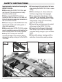
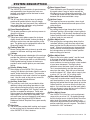
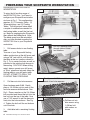
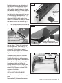
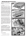
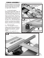
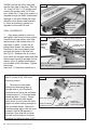
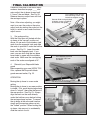
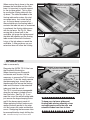
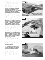
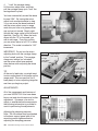
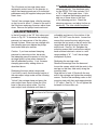
INCRA ® Patented Precision Woodworking Tools The only table saw fence with Automatic Positioning Control™ R R INCRA TS-III ULTRA OWNER’S MANUAL Please read this manual before use and keep it at hand for easy reference. For many years, INCRA has been the accepted upgrade of choice for thousands of woodworkers seeking to improve the accuracy and repeatability of their wood cutting tools. Today, your search for the perfectly placed cut will come to an end. Your Shopsmith workstation will be transformed and your skill elevated to a new level of performance. Now, take a few minutes to read through this owner’s manual, open up your toolbox, and let the transformation begin. CONTENTS Safety Instructions System Description Preparing your Shopsmith Installing the Ultra Base Fence Assembly 2 3 4 6 7 Final Calibration Operation Adjustments Maintenance Warranty 9 10 13 15 15 SAFETY INSTRUCTIONS Important safety instructions for using the INCRA TS-III Ultra ■ Always keep both hands behind the fence when moving the INCRA TS-III Ultra to a new setting. ■ Before using the INCRA TS-III Ultra, read and follow all of the instructions and safety information in this manual. ■ Before making a cut, always make sure that the carriage clamp is fully engaged. ■ Use appropriate safety devices. Keep hands clear of the saw blade! Always use a push stick, rubber soled push block, or other safety devices to keep your hands safely away from the saw blade. ■ When using the INCRA TS-III Ultra in conjunction with any other tool, first read and follow all instructions and safety information in that tool’s owner’s manual. ■ Never let any part of the INCRA TS-III Ultra interfere with another tool’s safety guards or other safety equipment. ■ Never let the saw blade come into contact with any part of the INCRA TS-III Ultra. ■ Always hold the Shopsmith table height crank firmly as you loosen the table height lock when making changes to your worktable height. ■ Before using your INCRA TS-III Ultra, make sure all mounting screws are tight and that the black clamping knobs are securely tightened. ■ Always turn off the power and make sure that the blade is fully stationary before changing the setting on any part of the INCRA TS-III Ultra. System Photo ■ Wear safety glasses, hearing protection, and follow all normal shop safety practices. Precision Racks Micro Adjust 1 16 2 15 14 4 11 12 13 3 4 6 5 10 INCRA Woodworking Tools & Precision Rules 9 7 8 SYSTEM DESCRIPTION 1 Positioning Control 2 3 4 5 6 7 8 9 The INCRA TS-III Ultra obtains its great accuracy and repeatability from the precision cast sawtoothed racks which position the fence in exact increments of 1/32”. Rip Fence The 36” long heavy-duty rip fence is precision machined for perfect flatness along its length. T-slots along the front face permit easy addition of user made wooden subfences using standard ¼-20 hex bolts and hex nuts. Fence Mounting Bracket This bracket provides a quick and easy means to attach the rip fence. Rip Fence Glides These heavy duty glides support the rip fence slightly above the worktable surface providing an effortless motion from one fence position to the next. The glides can be configured for either the Shopsmith model 510 or 520 rails. Floating Table Tab Moves floating table with rip fence to provide extra support for the fence and large work pieces. Carriage The reinforced square tube design of the carriage provides the ultimate in strength and support for your fence. The carriage rides on self-lubricating UHMW guide bearing surfaces in the base to provide a velvet smooth glide to your next fence setting. Primary Sliding Scale After setting up your INCRA TS-III Ultra and “zeroing” the fence to the blade, slide this scale to read 0” under the hairline cursor. The precision etched stainless steel scale is held on a magnetic track. Use this scale as the primary source for readout of fence to blade distance. Auxiliary Scale Slots Four auxiliary scale slots are provided to allow additional setups and cutting operations to take place without altering the primary scale position. Simply slide the supplied 1/32” “floating” scale into position as needed for reference. These extra slots are great for advanced joinery applications requiring the use of the INCRA templates. You can even leave your most frequently used joinery templates from the optional INCRA Master Reference Guide & Template Library permanently installed. Ultra Base The Ultra base provides both tracking and support for the carriage and is the control center for most of the INCRA TS-III Ultra’s features. 10 Base Support Panel 11 12 13 14 15 16 Once attached to your Shopsmith floating table, this panel makes it easy to add or remove the Ultra Base from your Shopsmith workstation. The T-slot design makes the final calibration alignment between the rip fence and blade a snap. Hairline Cursor The large hairline cursor provides a clear visual reference of the fence location and spans all five scale positions. Carriage Clamp By pushing the carriage clamp down into the “unlocked” position, the carriage is free to glide to the next setting. Pull the clamp handle up into the “locked” position and the carriage is locked solidly in place, ready for your next cut. Micro Adjust Lever After pushing the carriage clamp down into the “unlocked” position, push the micro adjust lever down to place the Ultra Base into the “micro adjust mode”. After micro adjusting your fence position, simply reset the micro adjust lever and then pull the carriage clamp up into the “locked” position before making your next cut. Micro Adjust Knob When in the “micro adjust mode”, use this knob to fine-tune the position of the fence in one thousandth of an inch increments. A hairline cursor and easy-to-read scale give a clear readout of your fence movement. Turning the knob clockwise moves the fence closer to the blade. Turn it counterclockwise and the fence moves away from the cutter. Each full turn of the knob moves the fence 1/32”. Micro adjust range is plus or minus 1/4”, for a full 1/2” of vernier travel. Micro Adjust Scale with Zeroing Feature Large easy-to-read numbers make fine-tuning your fence position a snap, and once you’ve micro adjusted and pulled the carriage clamp up into the “locked” position, you can re-zero the scale if you desire. Just rotate the scale (not the knob) gently with your fingers to return the zero on the scale to its original position under the cursor. Micro Adjust Cursor Your INCRA TS-III Ultra has a micro adjustment range of plus or minus 1/4”. By sighting through the micro adjust cursor to the left end of the micro adjust knob, this feature tells you how far you have micro adjusted away from the mid-range (0”) position and which way you’ve gone. The scale is marked off in 1/32” increments. INCRA TS-III ULTRA Shopsmith Owner’s Manual PREPARING YOUR SHOPSMITH WORKSTATION PREPARING YOUR SHOPSMITH WORKSTATION To enjoy the full working range of the INCRA TSIII Ultra , you'll want to configure your Shopsmith workstation at shown in Fig. 1. This configuration requires, (2) 5' Connector Tubes, (2) Telescoping legs, and (2) Floating Tables. The instructions below detail a couple of modifications needed for the floating tables as well the final set up. Begin by unplugging the Shopsmith then remove the blade guard. Note: The blade guard must be reinstalled after you have finished mounting the INCRA TSIII Ultra to your Shopsmith workstation. 1 Drill access holes in one floating table Turn one of your Shopsmith floating tables upside down at the drill press and using a 3/8" twist drill bit, drill through the table at the two locations shown in Fig. 2. Try to center the holes as well as possible on the existing hole bosses in the casting. CAUTION: When drilling metal, always operate your drill press at "Slow" speed and securely clamp the floating table to your drill press table. DO NOT ATTEMPT TO DRILL THE FLOATING TABLE FREEHAND. 2 Figure 2 Figure 3 Pull hex nuts into hole recesses Open hardware pack B-06. Gently press a 1/4-20 hex nut into each of the two hole recesses drilled above. See Fig 3. Place a washer on the 1/4-20 hex bolt provided and thread the bolt into the hex nut from the top of the table. Now use a 7/16" wrench to pull the hex nuts firmly into the hole recesses. See Fig. 4. Tighten the bolt until the nut bottoms out in the hole. 3 Add table tab to remaining floating table Figure 1 INCRA Woodworking Tools & Precision Rules Drill 3/8” diameter holes through table at these two locations Gently press ¼-20 hex nut into each of two hole recesses Figure 4 Pull hex nut into hole recess using ¼-20 hex bolt with washer as shown Mark drill centers on the right edge of the remaining floating table as shown in Fig. 5 then use the (2) #10 x 1/2" self drilling phillips head fasteners to attach the table tab. See Fig. 6. Leave each of the two fasteners slightly loose to allow the tab to pivot down and out of the way for other floating table applications. For the model 510 floating table, add self adhesive UHMW to both ends of the tubular rails. Adhere the pads just inside the tubes at the top as shown in Fig. 7. 4 Final Shopsmith workstation set up Loosen the headstock and carriage Figure 5 1 ¾” 6” 9/1 4 6” /1 3 1 #10 x 5/8” self-drilling fasteners table tab Figure 6 Figure 7 For Model 510 floating table, adhere UHMW pads as shown to front and rear rails locks and slide both to the far left end of the way tubes. Tighten the headstock and carriage locks. Now insert (2) 5' extension tubes into the worktable rails allowing 32" of the tubes to extend beyond the right edge of the worktable. Tighten the locking thumbscrews. Slide the floating table with table tab onto the right end of extension tubes. Slide floating table with drilled access holes onto the right end of the extension tubes. Position this floating table 23" from the worktable and tighten the locking thumbscrews. Now attach the telescoping legs as shown in Fig. 8 and extend to hold the work surface at 90 degrees to the blade. Leave fasteners loose enough to allow tab to pivot Figure 8 32” 23” INSTALLING THE ULTRA BASE 1 Remove endcap from base support panel Remove the (2) fasteners that secure INCRA TS-III ULTRA Shopsmith Owner’s Manual INSTALLING THE ULTRA BASE the endcap to one end of the base support panel and remove the endcap. See Fig. 9. 2 Attach the Ultra base to base support panel Open hardware pack B-07. Place #10 washers on each of the (6) #10-32 x 1/ 2" phillips pan head screws. Insert four of the screws through the slotted holes on the Ultra base and loosely thread a #10-32 hex nut onto each screw. Insert the remaining two screws through the two inside holes located in the middle of the Ultra's base and attach hex nuts. Slide the hex nuts on all six screws into the T-slots on the base support panel. The (4) screws/nuts in the slotted holes slide into the outer T-slots. The (2) screws/nuts inside the Ultra's base slide into the inner T-slots. See Fig. 10. Position the Ultra's base on the base support panel as shown in Fig. 11. (Edge of the Ultra base should be about 3 1/4" from the end of the panel.) Use a square to align the Ultra base at 90 degrees to the panel and tighten the four screws installed in the slotted holes only. Do not tighten the two screws inside the Ultra's base at this time. Replace the base support panel end cap removed earlier. 3 Attach base support panel to Shopsmith floating table. Using the (2) 1/4-20 x 1 1/2" threaded knobs with washers, attach the base support panel to the floating table as shown in Fig. 12. Visually align the leading edge of the base support panel parallel with the grooves in the top of the floating table and tighten the threaded knobs. Figure 9 Base support panel End cap Figure 10 2 fasteners mentioned in Fig. 11 below slide into inside T-slots 4 screws/nuts for slotted holes on Ultra base slide into outer T‑slots Figure 11 Do not tighten these 2 screws at this time ” 3¼ Square Ultra base to support panel and tighten fasteners Figure 12 FENCE ASSEMBLY 1 Slide carriage into Ultra base INCRA Woodworking Tools & Precision Rules ¼-20 x 1 ½” threaded knobs with washers FENCE ASSEMBLY Slide the carriage into the Ultra's base and position the fence mounting bracket above the right edge of the worktable. Pull the carriage clamp up to lock the carriage in place. See Fig. 13. 2 Loosely attach rip fence Open hardware pack B-08. Place a 1/4" flat washer on each of (2) 1/4-20 x 1/2" socket head cap screws and insert the screws through the slotted holes on the fence mounting bracket. Thread the 1/ 4-20 square nuts onto the screws, then slide the fence onto the square nuts as shown in Fig. 14, capturing the nuts in the upper T-slot. Allow the infeed end of the fence to overhang the worktable by about 3". See Fig. 15. Do not tighten the fence mounting screws at this time. Figure 13 Fence mounting bracket Align fence mounting bracket above edge of worktable and lock carriage clamp carriage Figure 14 rip fence capture nut in upper T-slot 3 Attach fence glides Note: The fence glides included in hardware pack B-08 are configured for the Shopsmith model 520. To convert the glide for the model 510, see the sidebar. ¼-20 x ½” socket head fastener with washer Place one of the supplied 3/4" x 3" cardboard spacers under each end of Figure 15 as shown in Fig. 16 and attach the fence the two fence glides to the rear of the fence using (4) 1/4-20 x 1/2 socket head cap screws, 1/4" washers and 1/4-20 square nuts. Capture the nuts in the lower T-slot on the fence. See Fig. 17. Slide the glide onto the fence and position it so that the UHMW pad on the underside sits on top of the Shopsmith rail and the white nylon spacer is about 1/32" away from the outside of the rail. Visually level the glide and tighten the fasteners. Finally tighten the (2) fasteners that secure the fence to the fence mounting bracket. Take care not to raise or lower the fence mounting bracket as you tighten the screws. Remove and save the cardboard spacers. SIDEBAR Converting the fence 3” glides for the model 510 Remove the fasteners and the large diameter nylon spacers from each of the two fence glides. Remove one of the UHMW bearing strips from each of the fence glides as shown. Remove the INCRA TS-III ULTRA Shopsmith Owner’s Manual UHMW from the left side of one glide and the right side of the other. See Fig. 18. Using 1/4-20 x 1-1/2" phillips head screws with washers and 1/4-20 lock nuts, attach the 1" long nylon spacers to the glide through the holes located near the edge of the glide. Retain the large diameter nylon spacers and fasteners for future re-conversion should you upgrade to the model 520 rails. Figure 16 First: Place cardboard spacers under fence Second: Attach fence glide FINAL CALIBRATION 1 Align fence parallel to miter slot and tighten Ultra base mounting screws Unlock the carriage clamp, then slide the fence up to the nearest miter slot and clamp in place. Loosen the (4) phillips head screws that secure the Ultra base to the base support panel and align the fence to the miter slot. See Fig. 19. Retighten the (4) screws. Now unlock the carriage clamp and slide the carriage forward far enough to allow access to the (2) phillips head screws in the middle of the Ultra base. Tighten the screws. Important: If it becomes necessary to realign the fence in the future, make sure to loosen all (6) Ultra base mounting screws. 2 Zero fence to saw blade Retract the telescoping legs at the right end of your Shopsmith workstation and lower the worktable to expose about 1" of the saw blade above the table. Caution: Always hold the Shopsmith table height crank firmly as you loosen the table height lock when making changes to your worktable height. Reposition the telescoping legs so that the work surface is held at 90 degrees to the blade. Now slide the rip fence forward until just before it contacts the blade (to within less than 1/32"). INCRA Woodworking Tools & Precision Rules Figure 17 Fence glide ¼-20 x ½” socket fasteners with washers and square nuts Capture nuts in lower T‑slot UHMW pad sits on top of rail Nylon spacer approximately 1/32” away from rail Figure 18 Remove UHMW pads from opposite sides of glides Fence glide Attach conversion hardware here 1” long nylon spacer ¼-20 x 1½” Phillips head screw with washer FINAL CALIBRATION Place the Ultra base in the micro adjust mode as described on page ____ and micro adjust the rip fence forward until it "kisses" the saw blade. See Fig. 20. Release the micro adjust lever and lock the carriage in place. Figure 19 Second: Slide carriage forward to access screws in middle of ULTRA base and tighten Note: After micro adjusting, you might want to re-zero the scale on the micro adjust knob by rotating the scale (not the knob) to return to zero under the micro adjust cursor. 3 Set scale position With the Ultra base still locked with the rip fence at the "zeroed" position set above, lift one end of the stainless steel scale from the magnetic track and slide the scale to position 0" under the hairline cursor. See Fig. 21. Lower the scale back onto the magnetic track. If you want, you can also slide the two-piece lexan scale to agree with the stainless steel scale. Make sure the overlapping ends of the scales are aligned at 16". First: Loosen all four ULTRA base mounting screws, align fence,then retighten screws Miter slot Figure 20 First: Slide fence forward to less than 1/32” from saw blade 4 Reinstall your Shopsmith blade guard Before operating your new INCRA TSIII Ultra, replace the Shopsmith blade guard removed earlier, Fig. 22. OPERATION Moving the rip fence to a new scale setting Moving the rip fence to any new position is simple. First, push the carriage clamp down to "unlock", then slide the fence to the new position. See Fig. 23. Always align the mark on the scale directly under the hairline cursor before locking the carriage clamp in place. To secure the rip fence at the new scale location, simply pull the carriage clamp up into the "locked" position. When moving the rip fence, take care not to accidentally slide the scale in its slot. Second: Micro adjust fence forward until fence “kisses” the blade Micro adjust zero INCRA TS-III ULTRA Shopsmith Owner’s Manual When moving the rip fence in the area between the worktable and the Ultra base it is important to provide support for the rip fence glides. This is done by moving the floating table with the rip fence. The table tab added to the floating table earlier makes this dual movement easy. Just rotate the tab up. As the rip fence is moved off of the worktable onto the floating table it contacts the table tab and, as movement is continued, the floating table moves with the rip fence. Se Fig 24. When moving the rip fence back to the worktable, just grasp the rip fence and the table tab together and the floating table moves forward with the fence. Let go of the tab when you reach the worktable. A little paste wax on your extension tubes will allow the floating Figure 21 With fence zeroed to blade, slide scale to read “0” under the hairline cursor Figure 22 OPERATION table to move easily. Removing the INCRA TS III Ultra from the Shopsmith Workstation When converting your Shopsmith to alternate work modes it will be necessary to remove the TSIII from the workstation. To do this simply remove the telescoping legs, loosen the two thumbscrews that secure the floating table and Ultra base to the extension tubes and slide the unit off. The TS III is much more manageable when the rip fence is locked close to the Ultra base. See Fig. 25. If you need the use of the extra floating table, just remove the large clamping knobs and lift the base support panel off. When replacing the unit make sure to realign the fence parallel to the miter slot and re-zero the scale and hairline cursor. Realigning the fence can often be accomplished by simply shifting the 10 INCRA Woodworking Tools & Precision Rules Figure 23 When moving fence forward, grasp table tab and fence to move floating table with rip fence Lower carriage clamp to unlock carriage TIP ▼▼▼▼▼▼▼▼▼▼▼▼▼ To keep your rip fence glides and floating table moving smoothly, clean and apply paste wax to the rails and extension tubes from time to time. ▲▲▲▲▲▲▲▲▲▲▲▲▲TIP floating table along the extension tubes, or by shifting the position of the base support panel on the floating table. Micro adjusting the rip fence position The micro adjust feature of your new INCRA TSIII Ultra allows for precise positioning of the rip fence to any location between the 1/32" tooth spacing of the INCRA racks. You'll find this feature extremely handy the next time you want to widen a mortise by a few thousandths of an inch when using your router table or for shaving a "hair" off the width of a tenon cut in table saw mode. Use the micro adjuster when cutting grooves to accept inlay strips for a flawless fit, or to loosen up a tight fitting joint. You'll find it extremely useful when "zeroing" to the fence to the bit or blade or for "centering" the cutter on your work piece when setting up for joinery operations. Let's use a "hands on" stepby-step approach for getting acquainted with, and using the various components of this important feature. Figure 24 When moving the fence backward, table tab moves floating table with rip fence Figure 25 Note: Before you micro adjust your fence position, you will usually want to make sure that the micro adjust scale reads "0" under the micro adjust cursor. To adjust, simply rotate the scale (not the knob) with your fingers. See Fig. 26. Now let's micro adjust the fence forward 1/64". See Fig. 27 as you follow the steps. 1 "Unlock" the carriage clamp Push the carriage clamp handle down to "unlock" the carriage. To remove TS-III from Shopsmith, slide floating table with ULTRA base off extension tubes Figure 26 2 Engage the micro adjust lever Push the micro adjust lever down to place the Ultra base into the micro adjust mode. 3 Micro adjust the fence position Turn the micro adjust knob clockwise 1/2 turn until you see the 1/64" mark appear under the hairline cursor. INCRA TS-III ULTRA Shopsmith Owner’s Manual 11 4 "Lock" the carriage clamp Lift the micro adjust lever, and then pull the carriage clamp up to "lock" the carriage back in place. Detail 26A You have successfully moved the fence forward 1/64". By turning the micro adjust knob counterclockwise in step 3, you can move the fence backward and the micro adjust cursor's range scale lets you know at a glance which way you've just moved. Simply sight through the range scale to the left end of the knob. See Fig. 28. When the knob aligns with the "0" on the scale, you are at mid-range. From this position, you can micro adjust a full 1/4" in either direction. The scale is marked in 1/32" increments. IMPORTANT: Do not turn the micro adjusting knob with the carriage clamp in the "locked" position. The carriage clamp must always be "unlocked" and the micro adjust lever pushed down before micro adjusting the fence position. Figure 27 First: Push carriage clamp down to unlock Second: Push micro adjust lever down Third: Turn micro adjust knob to fine tune Fourth: Reset micro adjust lever, then lock carriage clamp TIP At the end of each day, you might want to micro adjust back to mid-range on the range scale. This ensures that you'll have plenty of micro adjusting range the next time you begin a project. ADJUSTMENTS All of the components and features of you new INCRA TSIII Ultra have been factory set and should require no further adjustment. If however, you wish to adjust or recalibrate these components the following information is provided to assist in performing the adjustments. Adjusting the clamping pressure Note: The Ultra base must be attached to the base support panel with all six mounting screws tightened before adjusting the clamping pressure. 12 INCRA Woodworking Tools & Precision Rules Figure 28 Left end of micro adjust knob Range scale Sight through the scale to the left end of the knob Photo shows micro adjuster exactly at mid range The Ultra base and carriage clamp were designed to make it easy for the operator to adjust the clamping pressure to his individual preference using the supplied clamp pad shims. Here's how: "Unlock" the carriage clamp, slide the carriage so that its end is about 1" forward of the rear of the Ultra base and press the micro adjust lever down. Remove the phillips head screw and nylon washer that caps the end of the clamping pad slot. Your hardware pack for the INCRA TSIII Ultra includes (3) 6" x 7/8" x .005" clamp pad shims. If you want to increase the clamping pressure add one of these shims to the front of the clamping pad slot. Check the clamping pressure, and adjust further as necessary. The shim should be placed ADJUSTMENTS to the left (inside) of the 1/8" thick clamp pad shown in Fig. 29. To decrease the clamping pressure just remove one of the thin shims already in place. When you are satisfied with the clamping pressure replace the phillips head screw and nylon washer. Caution: If you have reduced clamping pressure by removing a shim, be certain that adequate pressure remains to hold the carriage rigidly in place when clamped in the fully extended position. If not, increase clamping pressure by adding shims as described above. Realigning the micro adjust range scale If you wish to verify the mid-range location of the microadjust range scale use the following procedure: "Unlock" the carriage clamp and press the micro adjust lever down to place the Ultra base in the micro adjust mode. Turn the micro adjust knob clockwise until there is noticeable resistance to the rotation of the knob. DO NOT force the knob. Loosen the screws that secure the micro adjust cursor and align the last mark on the left end of the range scale with the left end of the micro adjust knob. See Fig. 30. Retighten the mounting screws then turn the micro adjust knob counterclockwise to return to a midrange reading of "0". "Lock" the carriage clamp back in place. Realigning the carriage racks Remove the carriage from the base and loosen the screws which hold the racks to the carriage so that they slide easily along the mounting track. Align the end of rack #1 flush with the rear end of the carriage and tighten the mounting screws. Position the remaining racks on the mounting track with their ends approximately 1-1/2" apart. See Fig. 31. Do not tighten the fasteners for these racks yet. Figure 29 To change clamping pressure, add or remove shims to the left of 1/8” thick clamping pad Remove screw and washer INCRA TS-III ULTRA Shopsmith Owner’s Manual 13 Carefully slide the carriage back into the Ultra base, taking care not to change the position of the loose racks. Position the carriage so that the Ultra base is centered approximately between the ends of racks #1 and #2. See Fig. 32. With the carriage properly located you should be able to see one of the mounting screws for each of the two racks. Pull the carriage clamp up into the locked position and the rack on the clamping side of the Ultra base will automatically align rack #2 with rack #1. Tighten the accessible mounting screw on rack #2. Unlock the carriage clamp and move the carriage forward to tighten the other mounting screw on rack #2. Now locate the carriage so that the Ultra base is centered approximately between the ends of racks #2 and #3. Again, lock the carriage clamp to bridge the two racks and tighten the accessible mounting screw on rack #3. Then unlock the carriage and move forward to tighten the remaining screw on rack #3. Continue this "bridge and tighten" procedure for the remaining racks on the carriage. Adjusting the rip fence and carriage tracking If the carriage and rip fence are not gliding smoothly from the base to the blade the tracking problem can almost always be traced to one of two conditions. The carriage and Ultra base work best together when they move parallel to one another. The Ultra base supports one end of the carriage while the rip fence supports the other. If the carriage is mounted too high or too low to the rear of the rip fence, tracking problems typically occur. The solution for this particular condition is really quite simple. Just adjust the fence mounting bracket up or down on the rear of the rip fence. The "sweet spot" is just a few trys away. One method we have found that works 14 INCRA Woodworking Tools & Precision Rules Figure 30 First: In micro adjust mode, rotate knob clockwise until resistance is encountered Second: Loosen screws Third: Align last mark on left end of scale with left end of knob, then retighten screws Figure 31 First: Loosen screws that secure racks to mounting track 1½” approx. Third: Position all remaining racks 1½” apart Do not tighten screws for these racks yet Second: Align first rack with carriage end and retighten screws Figure 32 “Bridge” racks and tighten screws Bridge racks #1 & #2 by locking carriage clamp Rack #1 Rack #2 Racks are correctly bridged when one screw on each rack can be seen Rack #3 well is to loosen the fasteners that secure the rip fence to the carriage then slide the carriage to within 4" of the Ultra base. Lock the carriage clamp then tighten the fence mounting fasteners. If you find that the above adjustment does not take care of tracking problems, check that the mounting and tracking surfaces are aligned. First use a straight edge to make sure that the Shopsmith rails are aligned with one another. Refer to your Shopsmith instructional manual for information on realigning the rails. Finally check to make sure that the floating table that holds the TS III's base support panel is in parallel alignment with the Shopsmith worktable. If you find these two tables out of alignment, simply place shims between the base support panel and the floating table to bring the base support panel into parallel alignment with the main worktable. many years of virtually maintenance-free operation. In fact, just keeping your INCRA product clean is all you need to do to keep the tool in top shape. Occasionally, remove the carriage from the Ultra base and brush or blow out any sawdust or debris that may have accumulated. Use a toothbrush to clean the teeth on the INCRA racks on both the carriage and the base. A light application of paste wax to the top of the rails from time to time will keep the rails smooth and clean. MAINTENANCE Your INCRA TS III Ultra is designed to give MAINTENANCE Warranty Taylor Design Group, Inc. warrants this product for one year from date of purchase. We will repair any defects due to faulty material or workmanship, or at our option, replace the product free of charge. Please return the failing component only, postage prepaid, along with a description of the problem to the address below. This warranty does not apply to parts which have been subjected to improper use, alteration, or abuse. LIFETIME WARRANTY ON POSITIONING RACKS If an INCRA positioning rack in this tool becomes damaged for ANY reason, Taylor Design Group will replace it free of charge for as long as you own your tool. Return the damaged rack, transportation prepaid, and allow 2 weeks for delivery. Note: Replacements cannot be sent unless damaged racks have been received by Taylor Design Group. Made in America by: Taylor Design Group, Inc. ■ P.O. Box 810262 ■ Dallas, Texas 75381 ■ Tel: (972) 418-4811 ■ Fax: (972) 243-4277 ■ Web Site: www.incra.com ■ Printed in the U.S.A.© 2002, Taylor Design Group, Inc. INCRA is a registered trademark of Taylor Design Group, Inc. INCRA TS-III ULTRA Shopsmith Owner’s Manual 15 This page is intentionally blank. 16 INCRA Woodworking Tools & Precision Rules