1
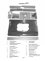
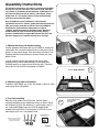
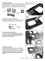
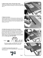
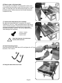
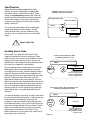
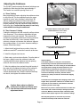
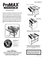
Owner's Manual
M axim um versatility...
Stock No. 40-031
Thank you for purchasing our ProMAX cast iron router table.
ProMAX can be mounted to your table saw, cabinet, or open
steel stand. The optional cast iron end cap (Stock No. 40044) can be added to give your router table a finished look
with 4" more table depth and rounded corners. Or, bolt two
router tables together - back to back. You must fabricate
your own stand or cabinet. For those mounting the ProMAX
to the right of your saw blade, and not directly to the table
saw's table, you must have a t-square type rip fence with
heavy steel rails to support the router table. Also, you must
fabricate your own support legs, or modify your existing
legs.
Upgrade your table
saw with ProMAX.
Cast Iron End Cap
(Stock No. 40-044)
Purchase our 4" x 27" cast iron end cap
and mount the router table to a cabinet!
shown with optional
featherboards and power
switch
Bench Dog, Inc.
3310 5th St. NE
Suite 100
Minneapolis, MN 55418
612.782.8205 main
612.788.2518 fax
800.786.8902 toll free
[email protected]
www.benchdog.com
QUESTIONS?
1-800-786-8902
Be sure to check out our web site for all the
latest and greatest accessories and tools.
www.benchdog.com
ProMAX - back to back. The ultimate tandem
router table. Perfect for professional
woodshops, and commercial rail and stile
production.
Read and understand the entire contents
of this manual before attempting assembly
or operation of this tool! Inspect contents
for shipping damage and shortages. Report
problems directly to Bench Dog, Inc.
2004 Bench Dog, Inc.
82-0040-06 0904
Contents of Box
1
1
1
1
2
2
2
2
6
4
1
1
2
2
2
2
cast iron routertop
28" ProFence
predrilled phenolic insert plate
accessory/miter track
Fence Hardware
3/8-16 x 2-1/2" hex bolts
3/8" nylon washers
2" t-knobs
1/4-20 x 3/4" hex bolts
1-1/8" t-knobs
1/4-20 x 40mm shoulder bolts
dual position bit guard
dust port
MDF subfences
aluminum knob spacers
aluminum jointer bars (pair)
j-hooks
1
1
3
3
3
4
8
4
4
10
12
13
3
2
Page 2
owner's manual
templae (paper)
Router Table Hardware
heavy rectangular shape washers
M10 x 1.5 x 40mm hex bolts
7/16-20 x 1-1/2" hex bolts
5/16-18 x 1-1/2" hex bolts
5/16" flat washers
5/16" lock washers
5/16" hex nuts
1/4-20 x 1" set screws
1/4-20 hex nuts
1/4-28 x 1/2" set screws
1/4-20 x 5/8" low head cap screws
1/4-20 x 1" phil. flat head machine
screw (black)
General Conditions / Limited Two Year Warranty
LIMITED TWO-YEAR WARRANTY
We make every effort to assure that our products meet quality and durability standards, and warrant to the original retail purchaser that this
product is free from defects in materials and workmanship for two years. Remedy shall be limited to Bench Dog’s choice of repair,
replacement or refund. This warranty does not provide remedy for consequential economic loss.
This is a limited two year warranty. It requires the purchaser to contact Bench Dog in writing within 30 days of discovering the defect.
Warranty does not apply to defects due directly or indirectly to misuse, abuse, negligence or accidents, repairs or alterations, or due to lack
of maintenance. It excludes components and parts not manufactured by Bench Dog, defects caused by failure to provide a suitable
installation environment, and damage caused by use for purposes other than those for which the product was designed. Bench Dog, Inc.
reserves the right to make product changes without notice and without obligation to make these changes on products previously sold. It
excludes warranties of fitness for a particular purpose.
If the product is defective, we reserve the right to fix it, replace it, or refund the cost of the product to you. Typically, this results in a refund.
All claims are limited to the two-year claims period. We must receive the product before a credit or refund will be issued. The warranty
language on the product or in the product’s manual may contain additional limitations, which govern.
If you wish to return something, call the dealer where you purchased the product. If you wish to return something purchased from Bench
Dog directly, call 1-800-786-8902 to receive an RMA number. Upon receipt and inspection of the goods, a credit or replacement will be
issued for defective products. Return of nondefective items to Bench Dog are subject to a 7% restocking charge. This is necessary due to
the cost of checking, repackaging, and inventorying the stock.
BENCH DOG DISCLAIMS AND BUYER EXPRESSLY WAIVES ANY AND ALL WARRANTIES, EXPRESS OR IMPLIED, INCLUDING BUT
NOT LIMITED TO, IMPLIED CONDITIONS OF FITNESS FOR A PARTICULAR PURPOSE, MERCHANTABILITY, OR ANY OTHER
MATTER.
Important Safety Points
Before operating your router table please read this manual thoroughly. Safety and use tips are contained in the manual.
This page is not the sole source of safety information. Retain the manual for future reference. Refer to your router
owner's manual for safety instructions regarding use of that tool. This manual is not an instruction book on how to do
woodworking with a power tool. We encourage all woodworkers to continually seek improvement in their woodworking skills,
regardless of their craftsmanship or years of experience. The router table, fence and accessories must only be used for their
intended purpose: woodworking via normal routing operations. “Normal operations” means basic shaping of wood in
conditions where grounded electricity, sharp tools, dust, and rapidly spinning parts can be used or encountered safely. The
following instructions elaborate on this concept.
1.
2.
3.
4.
5.
6.
7.
8.
9.
10.
11.
12.
13.
14.
15.
Do not use your router table as a step or seat.
The top and cabinet must be properly secured, and be level before use. Inspect your table and base for
damage and levelness prior to each use.
Keep work area clean, dry and well lit.
The hardware affixing the insert to the routertop must be installed for safe use. Tighten insert hold-down
screws before each use.
Safe operation requires a router table fence, bit guard, dust collection system, starting pin or fulcrum, and
speed reducer for large diameter bits. We recommend reducing router speed for 1" or larger diameter bits.
Consult your bit manufacturer for the exact speed.
Use the right tool for the job. Do not force a tool or attachment to do a job for which it was not designed.
Secure your work with a featherboard, clamps, or a vice when appropriate. The use of inappropriate
accessories may cause injury.
Wear safety glasses, dust mask, face shield and ear protection. This is not an exhaustive list. Every-day
eye glasses do not substitute for safety glasses.
Do not wear gloves or jewelry while using a power tool and ProMAX
Maintain your equipment and its accessories in good working condition. Look for wear, poor alignment of
moving parts, binding of moving parts, breakage, poor mounting, or other conditions that may affect
operation and safety. Repair or replace any damaged parts.
Disconnect the power before moving, adjusting, or repairing parts, or otherwise maintaining your router table
and any accessories you may be using.
Keep children, pets, and those who may disregard safety away from work area, cords, sockets and tools.
Wear snug fitting clothes and keep long hair back to avoid catching in moving parts.
Do not overreach. Maintain balanced footing and stance.
Stay alert. Use common sense.
Page 3
Assembly Instructions
The following instructions only apply to mounting the ProMAX
directly to a cast iron table saw. The pictures show a RIDGID
(very similar to Craftsman) brand table saw. ProMAX will fit on
any cast iron table saw with at least 27" table depth. Tables
deeper than 27" will require shims to fill the space between
your fence rails and the ProMAX.
Note: ProMAX can not be installed as a left extension
replacement on left tilt "cabinet" grade table saws because the
table saw's motor protrudes to the left. Nor can ProMAX be
installed as a right extension replacement on right tilt
"cabinet" grade table saws for the same reason. Mounting
ProMAX to the far right will avoid the protruding motors,
however, ProMAX must be supported with the two steel rails
that also support your T-square style rip fence and legs.
1
1
1. Remove the factory left extension wing.
Use the hardware that came with your ProMAX to install your
router table. Do not use the factory bolts, as they may not be
grade 5 or the proper length. If the necessary bolt size is not
supplied with this router table you must purchase your own
grade 5 bolts.
In most cases the fence rails support the factory table
extension wings. When bolted directly to your table saw,
ProMAX requires no support from the fence rails. Therefore,
fence rails do not need to be fastened to ProMAX.
2
3 or 4 hole pattern?
4
4
3
4
3
2. Determine your saw's bolt pattern.
Craftsman and Ridgid use a four bolt pattern. Most all other
saws use a three hole pattern.
3. Four hole mounting.
Most four hole patterns use 5/16 bolts. Use the heavy
rectangle washers for the middle two holes, as shown. Each
bolt receives (2) 5/16" flat washers, (1) lock washer, and (1)
nut. Late model Ridgid saws use 5/16-18 tapped holes
instead of through holes. If the bolt size is not 5/16-18, you
must supply your own. Use grade 5 bolts.
WASHER ORIENTATION
(bottom of table)
Middle two bolts receive the
heavy rectangle washers
against the router table
Page 4
33
heavy rectangle washer
in these middle
two holes.
4
3
4. Three bolt applications.
This pattern always uses the heavy rectangle washers on each
bolt. Delta brand uses the 7/16-20 x 1-1/2 hex bolts. Most others
(imports) use the M10 x 1.5 x 40mm hex bolts. If your bolt size
was not mentioned you must purchase your own. Only use grade
5 bolts.
4
Use the heavy rectangle washer
on all three bolts!
WASHER ORIENTATION
(bottom of table)
7/16-20 x 1-1/2"
hex bolts
M10 x 40mm hex
bolts (8.8 is stamped
on the head)
5
5. Install the insert plate leveling screws.
Install, as shown. Use the 1/4-20 x 1" set screws and 1/4" nuts.
You will adjust and tighten these screws in steps 8 and 9.
Thread the nuts
onto the 1/4-20 x 1"
set screws.
6. Lift the router table into position.
Install the bolts while a friend holds the table in position.
Just snug the bolts for now. Make absolutely certain both
surfaces are smooth, flat, and free of burrs before
mating the two tables together!
6
7. Tighten the router table.
Tighten the bolts gradually and evenly. Use a soft tipped
mallet to lightly tap the table surfaces. If your router table is
not flat with your table saw's table, you may need to shim it.
Use paper or brass shims. The tolerances of your ProMAX
are probably much higher than those of your table saw's.
Slight inaccuracies in alignment rarely pose a significant
problem.
7
Page 5
8. Adjust leveling screws until insert plate is flush.
Install the insert plate into the routertop. Adjust leveling screws
until the plate is flush with routertop. You will mount your router in
step 16.
8
9. Tighten the levelers.
Hold the leveler with the 1/8" hex wrench, and use your 7/16"
wrench to tighten the nut. This will prevent the assembly from
moving. Be sure to hold the hex wrench securely when tightening
the nut. It may be necessary to fine tune the adjustment after
installing your router.
9
10. Adjust miter gauge track to fit your miter gauge.
First test-fit your miter gauge into the track. If it's too tight,
squeeze the gib against the front wall of the miter track with a
pair of Channel Locks. Use something to prevent marring the
aluminum. Next, install the (12) 1/4-28 x 1/2" set screws.
Tightening the screws will deflect the gib into your miter gauge.
Tighten all screws uniformly and gradually until the desired fit is
achieved. Miter gauge NOT INCLUDED.
1/4-28 x 1/2"
set screw
front
wall
10
gib
This miter track ONLY fits standard 3/8" x 3/4" miter
gauge bars. Wax the slot and bar to reduce wear.
11. Install the accessory/miter gauge track.
Use the (3) 1/4-20 x 5/8 low head cap screws. Tighten with the
1/8" hex wrench.
Page 6
11
12
12. Install dust port.
Pull the dust port along the two 45º grooves in the back of the
fence until it snaps into place. The port may fit very tightly.
13. Install the (2) MDF subfences onto the fence.
Insert (4) 1/4-20 x 40mm shoulder bolts into the counter-bored
recess on the subfences. Light pressure may be required to seat
bolts properly. The bolts are designed to fit snugly to prevent
spinning. Note: the subfences have no specific left/right or
up/down orientation.
14. Attach fence.
Use the (2) 3/8-16 x 2-1/2" hex bolts, (2) aluminum knob spacers,
(2) 3/8" nylon washers and (2) 3/8" (large) T-knobs.
T-knob
13
14
fence
spacer
nylon washer
cast iron
router table
3/8-16 x 2-1/2" hex bolt
15. Attach the dual position bit guard to fence.
Pre-assemble the guard with the (2) 1/4-20 x 3/4" hex bolts and
(2) knobs. Slide both bolt heads into the fence's T-slot to attach
to fence.
Note: The bit guard is designed for dual positioning. The larger,
curved side is used for general routing with small and medium
sized bits. The smaller angled side is intended for edge jointing
and small diameter bits.
Page 7
15
16. Mount router to the insert plate.
This insert plate is predrilled to fit most popular routers, and
comes with proper mounting screws for these routers. In some
cases, you must drill your own holes and purchase your own
mounting screws. Please reference the included template to
complete this step.
17. Install router and plate into the routertop.
Re-adjust the insert plate flush if necessary (see step 8).
Install the (2) 1/4-20 x 1" flat head phillips screws into the two
corners of the insert plate. These screws prevent side-to-side
movement and keep the insert plate firmly seated while
preventing excessive vibration. Do not over tighten as this
could damage the insert plate.
16
17
1/4-20 x 1" (black)
flat head phillips
machine screw
!
Check the tightness of the hold-down
screws before each use!
18
18. Install fence hang hooks.
Screw the hooks into the table about 3/8" and tighten the 1/4" jam
nuts with a 7/16" wrench.
19
19. Hang the fence when not in use.
Page 8
Operational Tips
File Sharp Edges
Some table saws have a bevel on the leading edge. You can
file your router table to match, if so desired.
Dust Collection
The integral dust collection port is designed to accept a
standard 2-1/2" fitting, typical on most shop vacs. Most of
these fittings actually measure 2-1/4" (outside diameter).
Bench Dog recommends 2-1/2" hose, or larger, because it is
more effective at evacuating dust and chips, and provides
proper air flow over the router motor. Any hose larger or
smaller than 2-1/2" requires an adapter you must provide. If
additional dust collection is needed, a dust port can be
added to your cabinet or motor area. DO NOT USE YOUR
ROUTER TABLE WITHOUT DUST COLLECTION!
Using Your Miter Gauge
The miter track has two slots: an accessory T-slot and a T-bar
compatible miter gauge slot. The accessory T-slot is the
narrower of the two. It accepts 1/4" hex bolts for attaching
Feather-Loc featherboards. The miter gauge slot is used in
conjunction with a miter gauge, and fits standard 3/8" x 3/4"
miter bars (with or without the T-bar). The miter gauge is not
included.
To adjust fence perpendicular to miter gauge, set miter gauge
to 90º, and place in slot (make sure miter track is adjusted,
see step 10). Loosen the fence's T-knobs and align the miter
gauge to fence using a square, as shown.
Page 9
Feed Direction
Always feed the workpiece against the cutter
rotation, as shown. Feeding the workpiece with
the cutter rotation is called "climb cutting". Climb
cutting is very dangerous, because the cutter will
grab the workpiece and thrust it the same direction
as the cutter rotation. Even small router bits will
overpower your ability to hold onto the workpiece
during a climb cut.
A typical set-up. Here, the fence is
partially covering the router bit.
routertop (top view)
router bit rotation
Fence
Do not use this router table until you understand
proper feed direction and bit rotation. If climb
cutting is still unclear, ask your retailer for help,
give us a call, or reference a book on router table
usage.
!
workpiece
Proper feed direction
Never Climb Cut!
Avoiding Fence Traps
Fence traps occur when the work piece is fully
"trapped" between the router bit and fence. Fence
traps pose two real concerns: the possibility of climb
feeding, and human exposure to the router bit. As
stated earlier, climb cutting should be avoided as loss
of control of the operation is a possibility!
A classic trap resulting in a climb
cut. Always avoid this set-up!
Fence
workpiece
The top drawing shows a classic trap to be avoided.
What appears as a normal feed direction (working
from right to left) is wrong, and will instead produce a
climb cut. Because the work piece is trapped it can
easily be pulled from one's grip and thrown with great
velocity. Feeding the stock from left to right will
eliminate the climb cut but not the danger. It will be
difficult to keep the stock tight against the fence as the
bit's rotation will thrust the stock away from the fence.
Also, your body will be dangerously exposed to the
spinning router bit. The bit guard will not protect you
against flying stock, nor guard against this level of
exposure.
The second drawing is not a trap, as long as the router
bit cuts only partially into the stock. In other words, the
router bit must not completely cut through the
workpiece. In this cut, the bit will grab and push the
stock toward the fence. This is good, as the fence will
control the workpiece better than your hands. Typical
dado cuts resemble this set-up, and are commonly
performed on router tables. If the dado is to be
widened with two (or more) passes, be careful not to
set a classic trap or climb cut.
NO!
b it
r o t a ti o n
This feed direction will
result in a climb cut because
the stock is trapped between
the fence and the router bit.
Not a trap as long as the router bit does not
cut all the way through the stock.
Fence
OK for
dadoes
only
workpiece
b it
r o t a ti o n
Here the feed direction is
correct because the router
bit does not cut all the way
through the stock.
Page 10
Adjusting the Subfences
The (2) MDF (medium density fiberboard) subfences are
designed to slide along the fence approximately 2".
This results in a router bit opening from 0 to 4".
A. "Close" Setting
Many applications require adjusting the subfences close
to the router bit. This accomplishes nearly the same
benefits of a true "zero clearance" setting (see "B")
without cutting the subfences. Before the router is
turned on, and after the fence and router bit height are
properly adjusted, slide the subfences toward the bit to
reduce the gap. Confirm that the router bit can freely
rotate without touching the subfences!
The infeed subfence is wide open, and the
outfeed subfence is set to "close".
B. "Zero Clearance" Setting
Cutting the subfences into the router bit profile produces
"zero clearance". Zero clearance eliminates the gap
between the fence and router bit. This prevents the
workpiece from getting pulled into the fence just before
the router bit. Moreover, a zero clearance setting
achieves a cleaner cut because the subfence supports
the workpiece fibers. If a true zero clearance setting is
desired, follow these steps:
Router Bit Guide Bearing
outfeed subfence
Here the infeed subfence has been
adjusted to zero clearance.
1. Adjust the bit height and fence position. Note: the
subfences must NOT contact the router bit at this time.
outfeed subfence
2. Install the bit guard and secure.
4. Start router, and use dust collection. From the back of
the fence, slightly loosen the subfence knobs and
carefully slide the infeed subfence into the spinning
router bit. Hold onto the subfence knobs.
5. After the subfence has reached the guide bearing of
the router bit, fully tighten the knobs on the subfence.
Note: If the bit does not have a guide bearing (i.e.
vertical raised panel bits), slide the subfence half-way
into the bit, then tighten the subfence knobs.
!
Caution: Never adjust or slide the
subfences from the front! Always work
from the back with both hands on the
adjustment knobs.
infeed subfence
infeed subfence
Important Notes:
The outfeed subfence is rarely set to zero clearance,
because doing so has little performance benefit and can
damage the subfence. A "close" setting is more desirable for
most applications. Setting the outfeed subfence to zero
requires great care because the router bit can cause a
portion of the subfence to chip or break. If an outfeed zero
clearance is absolutely necessary, slide the outfeed
subfence very slowly into the bit to minimize the chipping
and tearing.
The subfences can be flipped when changing profiles or bit
heights. New, replacement subfences are available when a
new profile is to be created or if the subfence cannot be
trimmed to provide a fresh edge.
MDF works very well as a subfence because it is softer than
most woods and is much less likely to damage expensive
router bits. MDF also retains the shape of delicate profiles
and thus allows proper support for zero clearance settings.
When adjusting the fence, ensure that no part of the
aluminum fence body could contact the router bit.
Page 11
Jointing
Jointing is the process of making flat, square and straight mating edges.
Jointing is necessary when two boards are edge glued to create a larger
panel. It is also used to "fit" pieces together, as well as to trim stock to
size.
Note: Jointing on a router table is not intended to replace a free-standing
power jointer, especially for stock wider than 1.25". However, jointing with
the router table does have advantages over the jointer. First, small and
short pieces of wood can be safely jointed because the opening of the
fence can be made very small: about 1/2". Second, the quality of the cut
is usually better because the router bit spins much faster than the
jointer's cutter head. A faster cutter speed is especially useful on woods
prone to tear-out, like bird's eye maple and quilted cherry. Be sure not to
move too slowly, as this will leave burn marks in your workpiece.
In this photo, the user is sliding the
second bar into position. Be sure to
tighten the subfence knobs when done!
Note the small "v"
grooves. Always install
the bars in pairs.
Your fence has built-in jointing slots to accept the (2) small aluminum
jointer bars that shipped with your router table. Installed in pairs, these
bars "shim out" the out feed subfence either 1/32" or 5/64" (2mm).
Use slots 1 and 3 for
5/64" (2mm) cuts.
Set-up
Unplug router and install a 1/2" diameter straight or spiral up-cut router
bit.
1
2
Use slots 2 and 4 for
1/32" cuts.
Caution: Use only 1/2" shank bits for jointing. The bit's cutting
length must not exceed 1.25". Set the bit height to 1.25" or less.
3
Loosen the outfeed subfence mounting knobs and slide both aluminum
jointer bars (always installed in pairs!) under the outfeed subfence in
either the 2nd and 4th slots, or the 1st and 3rd slots (see illustration).
4
outfeed
subfence
Use a straight edge to adjust the router bit and outfeed subfence to the
same plane (see illustration below). Readjust if necessary. Remove
straight edge when done.
If board "snipe" occurs, realign the outfeed subfence to the router bit. Don't be
surprised if it takes a few tries to master
this operation.
Slide both subfences toward the bit to decrease the amount of gap
around the router bit. Be sure the subfences are not touching the router
bit. Also be sure the router bit is not touching the fence's aluminum body.
Tighten the subfence knobs and place the bit guard in position.
snipe
First make a test cut in scrap stock. Readjust if necessary.
(Bit guard not shown for clarity, only!)
fence (top view)
jointer bars
outfeed subfence
!
Always use a push
stick or push pad.
router
bit
infeed subfence
straight edge - remove before jointing!!!
workpiece
Use a straight edge to set
outfeed subfence and
router bit to same plane.
Feed Direction
Page 12