1
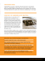
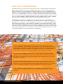
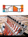
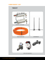
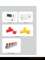
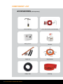
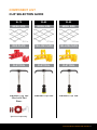
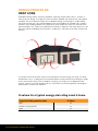
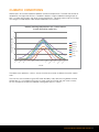
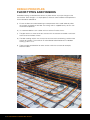
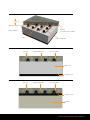
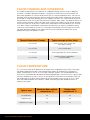
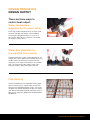
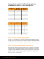
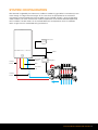
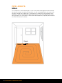
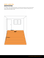
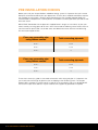
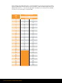
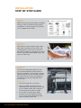
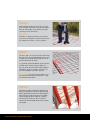
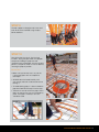
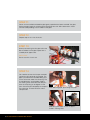
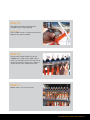
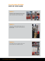
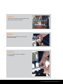
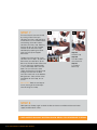
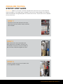
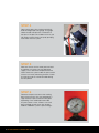
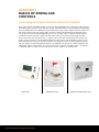
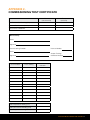
AUSPEX
RADIANT
UNDERFLOOR
HEATING
TRAINING MANUAL
Contents
INTRODUCTION 4
COMPONENT LIST 8
DESIGN PRINCIPLES
12
SYSTEM CONFIGURATION
19
PIPE LAYOUTS
20
PRE INSTALLATION CHECKS
22
STEP BY STEP GUIDES
25
Installation 26
Filling and Venting 32
Pressure Testing
35
Commissioning and System Start Up
38
APPENDIX 1. Basics of Zoning and Controls
40
APPENDIX 2. Commissioning Test Certificate
41
AUSPEX RADIANT UNDERFLOOR HEATING 3
BENEFITS OF
THE AUSPEX
RADIANT
UNDERFLOOR
HEATING SYSTEM
4 AUSPEX RADIANT UNDERFLOOR HEATING
THE BASIC IDEA
The ground floor in many houses is made up of a large slab of concrete or is constructed with
wooden joists and plywood floors. The basic idea is to use this floor area as a radiator. Coils of
pipe run under the floor, supplied with heated water which circulates through the coils. The surface
temperature required to produce a comfortable temperature in this application is much lower than in
a conventional ducted air or wet radiator system, and the heat is produced where it is most needed.
HISTORY OF UNDERFLOOR HEATING
Underfloor heating is not a new idea; over 2000
years ago the Romans developed warm air
underfloor heating systems known as hypocausts,
taking their name from the Greek meaning ‘heat
from below’. These were built so widely that original
examples (not still working) can be found at sites all
over the former Roman Empire even today. The floor
was raised above the ground by pillars so that hot
air and smoke from furnaces could pass through
these enclosed areas and heat the room above.
In the early 1980’s there were still examples of the
modern warm air systems in use but these were
going out of fashion and were being replaced with
wet radiator systems.
At the same time electric underfloor systems, installed in the 1960’s, were also going out of favour
because of running cost and practical control problems. The running cost problems often arose as
a result of the way they were run and the generally poor levels of home insulation. The availability of
more sophisticated types of control and improved levels of insulation has helped to encourage the
current growth in underfloor heating systems.
REDUCED FUEL COSTS CAN SAVE ON GAS BILLS.
HIGHER COMFORT LEVEL, WITH EVEN HEAT.
THE HEATING SYSTEM IS OUT OF SIGHT (PROTECTED
FROM ANY EXTERNAL DAMAGE).
THE DUST AND AIRBORNE PARTICLES LIKE POLLEN ARE
NOT SPREAD SO QUICKLY THROUGH THE BUILDING, WHEN
COMPARED WITH FORCED AIR SYSTEMS. THE HOUSE IS
LEFT A MORE HEALTHY, ALLERGY-FREE ENVIRONMENT.
QUIET OPERATION AND NO DISTURBANCE FROM
BACKGROUND NOISE OR AIR MOVEMENT FROM DUCTED
AIR HEATING SYSTEMS.
AUSPEX RADIANT UNDERFLOOR HEATING 5
HOW THE SYSTEM WORKS
Underfloor heating is the closest form of heating that achieves the ideal temperature profile which
gives the greatest comfort. The most acceptable indoor climate is a floor surface temperature of
between 22 and 26°C and the temperature around the head at 19 to 20°C. Underfloor heating
circulates water under the floor at about 27°C creating a temperature in the lower part of the room
of 20 to 21°C, and tapering off to 19 to 20°C around the head. Other heat emitters like ducted air
push hot air around the room producing higher temperatures around the head as high as 24°C, but
only 16°C around the body. Therefore, compared with other available heating systems, underfloor
heating creates a higher level of comfort by truly surrounding the body with warmth.
As underfloor heating relies on a large thermal mass like concrete, it can achieve optimum
thermal comfort at much lower temperatures which leads to fuel cost savings. Running at lower
temperatures, it also allows for use of more efficient heat sources such as condensing gas boilers,
again lowering the running costs. By comparison, ducted air cannot achieve efficiencies as low as
warm water underfloor heating due to air having a lower heat capacity than water. Ducted air also
increases heat loss by increasing air infiltration with airflow. Additionally, the heat loss from the floor
needs to be compensated for with a ducted air system whereas underfloor heating uses this area
as the heating appliance, so has lower heat losses to overcome.
Energy Efficient with Minimal Maintenance Costs
An Auspex Radiant underfloor heating system is the most efficient form of heating. The
system is designed to achieve maximum energy efficiency using low temperature water. The
low temperature floor gradually heats people and objects within the room. Floor temperatures
are designed to work at 29°C or below. The ongoing maintenance of an underfloor heating
system is minimal and costs are very small due to the small number of moving parts.
Quick and Easy to Install
An Auspex Radiant underfloor heating system is simple to install with everything needed
supplied in the kit. The revolutionary Smart Clip system used to fix the pipe to the reinforcing
mesh allows for installation of the system in record time. An average home can have all the
pipe laid in just four hours.
Clean, Healthy and Allergy Free Environment
An Auspex Radiant underfloor heating system relies on a natural movement of air unlike
ducted air which forces air around the room. This keeps the transfer of dust, pollen and other
particles to a minimum leaving a clean environment for the home owner to live in. The system
is silent in its operation and does not cause any disturbances through noise pollution.
Invisible Heating System with Design Freedom
The Auspex Radiant underfloor heating system is completely invisible and out of sight
enabling planners, designers and home owners to plan the layout of the home without any
restrictions.
6 AUSPEX RADIANT UNDERFLOOR HEATING
AUSPEX RADIANT UNDERFLOOR HEATING 7
COMPONENT LIST
THE KIT
Manifold - 6, 9 or 12 port
Auspex Radiant Pipe
Mixer and Pump Station
8 AUSPEX RADIANT UNDERFLOOR HEATING
Manifold Stand
Thermostat
Wiring Box
Smart Clips
Auspex Connectors
AUSPEX RADIANT UNDERFLOOR HEATING 9
COMPONENT LIST
ACCESSORIES (sold separately)
10 AUSPEX RADIANT UNDERFLOOR HEATING
Smart Clip Tool
Smart Clip Tool Base for Red Clips
Wiring Centre
Actuator
Repair Kit
Pipe Decoiler
Supply Pipe
Sleeving
COMPONENT LIST
CLIP SELECTION GUIDE
SL72
SL82
SL92
MESH SIZE
MESH SIZE
MESH SIZE
RED CLIPS
YELLOW CLIPS
YELLOW CLIPS
CLIP TOOL
CLIP TOOL
CLIP TOOL
Standard Clip Tool
fitted with Red
Base:
Standard Clip Tool
Standard Clip Tool
(purchased separately)
AUSPEX RADIANT UNDERFLOOR HEATING 11
DESIGN PRINCIPLES
HEAT LOSS
Underfloor heating outputs are always quoted in “Watts per square metre” (W/m ²). A Watt is a
measure of heat energy. The higher the amount of Watts required, the more fuel that is burned by
the boiler. The most important aspect of an underfloor heating system design is understanding
the amount of heat that is lost through different parts of the building, for example walls, windows
and roofs. Each building element has a particular U-value number. A U-value is a measure of the
thermal efficiency of a material or combination of materials. It represents the rate of heat that is lost
from the inside of the building to the outside. In simple terms, the lower the U-value, the lower the
heat loss.
In Australia all new construction homes have to be built to a certain energy star rating. The levels
are between 0 to 10, 10 being the most thermally efficient. At the present time of writing this guide
all new construction houses have to abide by an energy star rating of 5 or 6 dependant upon
location. Australia is moving towards level 10 in the future but it will take significant technological
advancements to reach this milestone.
U-values for a typical energy star rating Level 5 home
Type of building construction
U-Value
Wall
0.5
Windows (Single glazed)
5.4
Roof
0.3
12 AUSPEX RADIANT UNDERFLOOR HEATING
CLIMATIC CONDITIONS
Different parts of Australia experience different outside air temperatures. The lower the outside air
temperature, the higher the heat loss. Therefore it requires a higher underfloor heating output (in
W/m ²) to cope with locations with lower winter temperatures. Generally homes built to an energy
star rating of 5 would require a floor output of between 30 to 40 W/m ².
Monthly Heating Requirements for a 220m2 house
in each Australian capital city
5
Average UFH heat load (kW)
4
Adelaide
3
Brisbane
Canberra
2
Hobart
Melbourne
1
Perth
Sydney
De
ce
m
be
r
No
ve
m
be
r
Oc
to
be
r
Se
pt
em
be
r
Au
gu
st
Ju
ly
Ju
ne
M
ay
Ap
ril
M
ar
ch
Fe
br
ua
ry
Ja
nu
ar
y
0
Month
The above chart represents a 220m ² house of similar construction in different Australian capital
cities.
The chart was constructed using the RETscreen feasibility study software using NASA historical
climate data. It is assumed that the house is of the same construction with the same U-values.
For this example the respective underfloor heating floor output is 30W/m ².
AUSPEX RADIANT UNDERFLOOR HEATING 13
DESIGN PRINCIPLES
FLOOR TYPES AND FINISHES
Underfloor heating can be fitted into almost any floor without any major changes to the
construction. Even though it is a simple process there are some fundamental requirements
which need to be adhered to:
a)Ensure the floor cannot be heated up to a temperature which could adversely affect
the strength and quality of the floor. The mixing valve is supplied factory set to a safe
maximum temperature.
b) It is recommended to use insulation with a maximum R value of 0.25.
c)The pipe work must have continuous contact with the concrete to enable a consistent
heat transfer to the floor surface.
d)The floor covering or finish must have a low resistance to heat allowing a uniform heat
transfer to the room. The maximum R value allowed to be fitted onto an underfloor
heating system is 0.15.
e)There must be consideration for other services within the concrete for example,
electrical cables.
14 AUSPEX RADIANT UNDERFLOOR HEATING
40mm Concrete Cover
Concrete
Total slab thickness 130mm
Reinforcing Mesh
Clips
Concrete
Auspex Radiant Pipe
Auspex Radiant Pipe
Reinforcing Mesh
Waffle Pod
Insulation Sheet
Concrete
Auspex Radiant Pipe
Reinforcing Mesh
Insulation Sheet
Substrate
AUSPEX RADIANT UNDERFLOOR HEATING 15
FLOOR FINISHES AND COVERINGS
The majority of floor finishes can cope with an underfloor heating system as long as adequate
insulation is installed underneath the floor. It is important to check with the manufacturer of the
floor covering product to ascertain whether there are any surface temperature limits. Tiles are the
best floor covering due to their high thermal conductivity enabling them to effectively transfer heat
to the room. If using timber flooring consult the supplier to ensure it has a low moisture content or
the potential exists for it to dry out and warp after installation. Most carpets are good conductors of
heat but special attention needs to be taken when selecting the underlay, paying specific attention
to the TOG value or R value (TOG is another measure of thermal resistance equal to 10 x R value).
It has been stated in the European standard that any floor finish on top of an underfloor heating
system must not exceed an R value 0.15. A key point to remember is that the higher the R value
the higher the flow temperature that needs to be set at the manifold mixer. Below are a list of
different floor types with different R values.
Thermal Resistance (R value)
Typical example of floor finish
0.00 m2K/W
2mm vinyl tile, 5mm ceramic tile,
3mm epoxy coating
0.05 m2K/W
25mm marble floor
0.10 m2K/W
9mm carpet floor tile, 13mm hardwood
0.15 m2K/W
Deep pile carpet, wood blocks,
22mm laminates
FLOOR TEMPERATURE
This is the main factor which determines the output of the underfloor heating system. The higher
the difference between the floor surface temperature and the air temperature, the higher the
output. Temperatures as low as 21°C can give a feeling of comfort. The standard BS EN 1264
states that a comfortable floor temperature should range between 16 and 26°C but it is permissible
to have a temperature as high as 29°C in an occupied area. Also within the standard it states that
the temperature of the floor surface containing connecting pipes can be as high as 35°C. These
areas are called peripheral areas. Below is a table summarising the floor temperature limits in
relation to area types.
Type of area
Maximum floor surface
temperature °C
Design room
temperature °C
Occupied area
29
20
Peripheral area
35
20
Bathroom or similar
33
24
16 AUSPEX RADIANT UNDERFLOOR HEATING
DESIGN PRINCIPLES
DESIGN OUTPUT
There are three ways to
control heat output:
Water temperature
(Adjusted by the mixer valve)
Increasing the flow temperature via the mixer valve,
increases the floor heat output. For example by
increasing the temperature from 30° C to 35°C
with 200mm pipe centres, it increases the output
by roughly 23 watts per m ².
Water flow (Adjusted by
the manifold flow meters)
The flow rate of the system can be adjusted via the
integral flow meters fitted to the manifold. By turning
the flow meter anti-clockwise increases the flow
rate which at the same time increases the available
heat. The range on the flow meter is from 0 to 5
litres per minute, 5 being the highest flow rate.
Pipe Spacing
The distance between the underfloor heating pipes
within the concrete has a direct effect on the heat
output of the underfloor heating system. The closer
the pipes are spaced together the higher the output
(see table on the following page). Generally 200mm
pipe centres will give a good evenly distributed floor
temperature.
AUSPEX RADIANT UNDERFLOOR HEATING 17
Average Floor outputs for different pipe spacing
for a tiled floor with a 5°C drop through floor.
Pipe Spacing
mm
Mean Water
Temperature °C
Floor Output
Watts/m ²
200
25
20
200
27
30
200
29
40
200
31
50
200
33
60
Pipe Spacing
mm
Mean Water
Temperature °C
Floor Output
Watts/m ²
300
26
20
300
29
30
300
32
40
300
35
50
300
38
60
PIPE DEPTH WITHIN CONCRETE
The depth of an Auspex pipe within a slab is directly related to the flow temperature. The deeper
the pipe is set within the concrete the higher the temperature requirement. Generally an underfloor
heating pipe should not be any higher than 40mm below the surface. If the pipe is above 40mm
then it will cause an uneven surface temperature. The deeper the pipe the more even the floor
temperature. This will store more energy due to a higher thermal mass and deliver better response
times.
PIPE SPACING WITHIN THE CONCRETE
An Auspex Radiant pipe spacing of 200mm will deliver the most economic and technically viable
solution from a design and installation perspective, although in some exceptional cases 300mm
spacing may be recommended for best heat output. One of the most important principles of pipe
spacing is the temperature variation on the floor. Based on studies the human foot cannot detect
a change in temperature with a difference of 2°C or below. The pipework at a depth of 40mm
below the surface with 200mm pipe centres will keep the temperature within a range whereby
temperature variations cannot be realised.
18 AUSPEX RADIANT UNDERFLOOR HEATING
SYSTEM CONFIGURATION
With demand instigated by the thermostat, the Bosch condensing gas boiler instantaneously heats
water through its integral heat exchanger. At the same time, the pump fitted at the manifold is
activated to circulate heated water from the boiler via the manifold, through a series of pipe loops
under the floor. The mixer valve controls the flow temperature to achieve the desired temperature
within the floor. The flow meters on the manifold balance that temperature across the different
rooms to give the most comfortable living environment.
Thermostat
Mains
Heating
Return
Cold mains
water in
Wiring Box
Gas
Hot water
out
Flow
Heating
Return
Return
AUSPEX RADIANT UNDERFLOOR HEATING 19
PIPE LAYOUTS
SNAIL
The snail pattern is where the flow pipe is run all the way around the edge of the room towards
the centre of the room in ever diminishing circles. As soon as the pipe reaches the centre a hair
pin bend is formed and the pipe work is reversed and run parallel to the flow pipe back to the
manifold. It is easier to achieve closer pipe centres with this system whilst reducing the risk of
kinking the pipe. This system offers a more uniform floor temperature, especially when the floor is
one of the main heat loss surfaces.
Supply
Return
20 AUSPEX RADIANT UNDERFLOOR HEATING
PIPE LAYOUTS
SERPENTINE
This pattern can be used when the room has only one main heat loss wall, or in long, narrow
areas. Feed the flow pipe alongside the exterior wall and then serpentine working your way
towards the lowest heat loss area.
Supply
Return
AUSPEX RADIANT UNDERFLOOR HEATING 21
PRE INSTALLATION CHECKS
Before you install your Auspex Radiant underfloor heating system it is important that you have the
floor plan to hand to be able to plan your pipe routes. The first job is to decide where best to place
the manifold, ensuring there is enough space allowed for the size manifold selected. Ideally the
manifold needs to be placed in a central position to enable the shortest pipe routes possible to and
from each circuit.
IMPORTANT: Remember that the pipe coils supplied come in lengths of 120 metres so plan your
routes carefully, ensuring pipes do not cross over. Please read the following rule of thumb charts to
see the maximum permissible circuit floor areas with different distances from the manifold using
200 and 300mm pipe centres.
Floor area covered by pipe
using 200mm centres
Total connecting pipework
20 m ²
20 m
22 m ²
10 m
24 m ²
0
Floor area covered by pipe
using 300mm centres
Total connecting pipework
30 m ²
20 m
33 m ²
10 m
36 m ²
0
These charts are only a guide as care needs to be taken whilst laying the pipe. It is important that
you visually check the length of pipe that you are clipping to the reinforcing mesh. The Auspex
Radiant pipe is marked at 1 metre intervals to aid you in the installation. Clips must be NO MORE
than 600 mm apart and cable ties may be used for extra support for pipe bends if required.
22 AUSPEX RADIANT UNDERFLOOR HEATING
TOOLS REQUIRED
01.
AUSPEX RADIANT KIT TO MATCH LAYOUT, IE. 6,9 OR 12 CIRCUIT
02.
SMART CLIP TOOL
03.
AUSPEX CRIMPING TOOL
04.
CORRECT SMART CLIPS TO FIT REINFORCING MESH
05.
TAPE MEASURE
06.
SUITABLE SPRAY CAN
07.
ADJUSTABLE SPANNER AND PIPE GRIPS
08.
SPIRIT LEVEL (IF NOT USING MANIFOLD STAND)
09.
SUITABLE WATER PRESSURE TESTER
10.
TESTING AND COMMISSIONING SHEET
11.
CAD DRAWING (PIPE LAYOUT DIAGRAM), AVAILABLE ON REQUEST
12.
CABLE TIES
AUSPEX RADIANT UNDERFLOOR HEATING 23
When reading your building floor plan it is recommended that you check your Auspex Radiant
maximum pipe length chart to work out how much pipe is used with different pipe centres and
different floor areas in m ². To ensure enough pipe is available to run to and from the manifold,
a maximum 100m coil length is recommended.
Pipe Centres mm
Floor
Area
m2
200
1
5
3
2
10
7
3
15
10
4
20
13
5
25
17
6
30
20
7
35
23
8
40
27
9
45
30
10
50
33
11
55
37
12
60
40
13
65
43
300
Metres of pipe
14
70
47
15
75
50
16
80
53
17
85
57
18
90
60
19
95
63
20
100
67
21
70
22
73
23
77
24
80
25
83
26
87
27
90
28
93
29
97
30
100
24 AUSPEX RADIANT UNDERFLOOR HEATING
STEP
BY STEP
GUIDES
AUSPEX RADIANT UNDERFLOOR HEATING 25
INSTALLATION
STEP BY STEP GUIDE
STEP 1
Before starting your Auspex Radiant underfloor
heating system we recommend checking all
components in the pack against our checklist
that is supplied within the box.
STEP 2
Upon request Auspex Radiant supply a floor
plan layout showing you all the circuits and
manifold positions. Each zone or room has a
data label assigned to it which gives you all the
relevant information required (pipe length, floor
area, circuit flow rate).
STEP 3
If you have not requested a floor plan then
you will need to decide the best position to
place the manifolds, ensuring there is enough
space allowed for the size manifolds selected.
We recommend in the most central position
to enable the shortest possible pipe routes
to each zone.
IMPORTANT
• No circuits longer than 120 metres.
• U
se the manifold stand to fix onto the
reinforcing mesh and simplify the mounting
of the manifolds. Make space allowance
for later fitting of the pump assembly.
• A
t this point, consider where supply
and return lines for the boiler are to be
run. If running these under the concrete,
allowance needs to be made.
26 AUSPEX RADIANT UNDERFLOOR HEATING
STEP 4
Next you need to mark out on the floor
with a suitable spray can or other method
marking the positions of all of the walls
and doorways, fixed benches and sanitary
fixtures. This is preferably done by the
builder before you come to the site. Then if
needed, mark piping flow and returns in a
different colour or method.
IMPORTANT Lay pipe a minimum of 15cm
from walls and route the pipe loops through
doorways. This is to prevent nails from
damaging pipe work when wall plates are
secured to the concrete.
STEP 5
Adjust the clip tool to a height that allows
you to operate it when standing upright.
Load clips in the tool.
AUSPEX RADIANT UNDERFLOOR HEATING 27
STEP 6
After loading the clip gun with clips you start
to fix the clips onto the mesh by pushing down
firmly on the handle, which releases the clip,
securing it to the steel mesh.
IMPORTANT
The mesh is spaced at 200mm wire centres.
If you wish to lay pipes at 300mm centres then
you need to fix at every 1.5 mesh squares.
STEP 7
The next step is to walk around the whole area
fixing the clips at the required pipe centres until
all zones are covered. Alternatively, the install
may be done room by room.
It is generally recommended to space the clips
at three mesh squares along straight runs,
but use closer spacing where more support is
needed eg. long runs, edges and when runs
are in the middle of the mesh squares.
IMPORTANT If you are laying the pipes using
the serpentine method, you need to fix a clip
at the end of every bend.
STEP 8
Load the first pipe coil onto the decoiler and
bring one end to the manifold. Feed the pipe
gently up behind the lower manifold ready for
connecting to the flow and return manifolds.
Leave enough length to allow for crimping
and connecting hose tail. Affix a red flow
sticker with the corresponding circuit number
to the pipe.
28 AUSPEX RADIANT UNDERFLOOR HEATING
STEP 9
Provide support to the pipe and a neat and
even fit off to the manifold using Auspex
bend stabilisers.
STEP 10
Start laying the first circuit. For first time
installers, laying the pipe needs two people:
one person holding the pipe coil and
unrolling it from the decoiler, with the second
person, a couple of metres in front or behind,
securing the pipe in position.
IMPORTANT
• Make sure you do not cross any circuits
if laying the pipes with the serpentine
technique.
• ALWAYS form the bend carefully with
your hands and work it around rather than
forcing it.
• To avoid bowing pipe, it is best to feed the
pipe from behind and step it into the clips.
• Take extra care not to kink the pipe. A kink
does not warrant the use of an emergency
joiner. If the pipe is kinked, a new roll
should be used.
DON’T
DO
AUSPEX RADIANT UNDERFLOOR HEATING 29
STEP 11
Return to the manifold and feed the pipe gently up behind the lower manifold. Cut pipe
leaving enough length for crimping and connecting hose tail. Affix a blue return sticker
with the corresponding circuit number to the pipe.
STEP 12
Repeat steps 8 to 11 for all circuits.
STEP 13
Start by connecting the first pipe coil to the
flow manifold. Cut the pipe square with a
suitable plastic pipe cutter.
IMPORTANT
Do not cut with a hack saw.
STEP 14
You need to connect the Auspex manifold
crimp hose tail connector to the pipe. The
pipe is pushed over the barbed fitting and
at the same time under the crimp ring. The
fit should be firm, and the pipe visible in
the viewing circle. Centralise the tool jaws
over the crimp ring at 90 degrees to the
14a
joint. Close the tool completely to compress
After deburring pipe, push fitting onto pipe
the crimp ring. The tool will click at final
compression.
14b
14c
Slide fitting onto pipe, ensure the pipe is
visible in viewing circle
30 AUSPEX RADIANT UNDERFLOOR HEATING
STEP 15
Now tighten the hose tail fitting onto the
manifold using a suitable spanner.
IMPORTANT
Check rubber washer is in place prior to fitting.
Replace with spare if required.
STEP 16
As part of the Auspex Radiant kit you are
supplied with a sheet of room label stickers
which you will need to attach onto the front of
the flow manifold. For each circuit, select the
sticker with the most suitable room name.
STEP 17
Repeat steps 13 to 16 for all circuits.
AUSPEX RADIANT UNDERFLOOR HEATING 31
FILLING AND VENTING
STEP BY STEP GUIDE
STEP 1
Disconnect caps and connect two hose unions
to both end caps or alternatively connect two
hoses onto drain valves with hose clamps.
STEP 2
Open both the blue and red isolation valves on
the drain points. They both need to be open to
fill the system.
STEP 3
Ensure both of the main isolation valves on the
left hand side of the manifold are closed.
32 AUSPEX RADIANT UNDERFLOOR HEATING
STEP 4
Shut off all of the loops by closing both valves
on the flow and return manifolds.
STEP 5
Connect the hose from the mains water tap
to the flow manifold.
STEP 6
Run a hose from the return manifold to
a suitable drain.
AUSPEX RADIANT UNDERFLOOR HEATING 33
STEP 7
Ensure all circuits are now closed,
by turning all the white caps
clockwise until they stop and lifting
all the black nuts on the flowmeters
and rotating all the flow meters
clockwise until they stop. Working
from left to right on the manifold,
remove the air from each loop
individually by opening the lower
white manual cap and upper
flow meter.
To open the white cap turn it anti
clockwise until it stops. To open the
flow meter you need to lift up the
black nut around the flow meter and
turn anti clockwise approximately
3 turns. Both loop valves are now
open. Turn on the mains water
supply and initially air will discharge
through the hose into the drain
until clear water with no air bubbles
being present. Close off the valves
and repeat for each loop, one at
a time.
6a
6b
6c
Step 6a.
Lift black cap
Step 6b.
Turn flow meter
anti-clockwise
Step 6c.
Push down
black cap
IMPORTANT Work on one loop at
a time, closing off all other loops
when flushing each loop.
STEP 8
Now open up all loops again on both the flow and return manifold and close off water
supply and both drain valves.
YOUR AUSPEX RADIANT SYSTEM IS NOW READY FOR PRESSURE TESTING
34 AUSPEX RADIANT UNDERFLOOR HEATING
PRESSURE TESTING
STEP BY STEP GUIDE
IMPORTANT Before any concrete is laid over the pipe work a pressure test must be carried out
and witnessed by a site manger. Upon completion of the test the Auspex Radiant test certificate
needs to be filled out and signed by both the installer and a witness. A pressure test kit is required
to carry out the test.
STEP 1
Close off the main flow and return ball valves
and make sure all circuit flow meters and white
caps are open.
STEP 2
Close off the drain valve connected to the
drain (lower return manifold). Leave the hose
connected in the event of a leak to enable the
pressure to be safely discharged into a drain.
STEP 3
Connect the pressure test kit to the drain valve
on the upper flow manifold.
AUSPEX RADIANT UNDERFLOOR HEATING 35
STEP 4
Open up the drain valve isolator and initially
read the integral pressure gauge. The gauge
needs to read 400 kpa with a maximum of
600 kpa. If the pressure is below this then you
will need to raise the pressure up by pumping
more water into the system.
STEP 5
Allow ten minutes for the water pressure level
to stabilise as the pressure may decrease
slightly. This is due to the temperature of the
water. Leave the system under this pressure for
at least 15 minutes, observing for leaks. Check
that the pressure has remained stable during
the test period.
STEP 6
Decrease the pressure now to the working
pressure of 200 kpa. You may experience a
slight increase in pressure due to the pipes
expanding. Once stabilised, leave under
this pressure for 1 hour. If there is no visual
pressure drop or leaks then your Auspex
Radiant underfloor system is pressure tight.
36 AUSPEX RADIANT UNDERFLOOR HEATING
STEP 7
Ask the site manager to sign off the test.
STEP 8
Auspex Radiant recommends that the system
is left under pressure at 200 kPa with the water
connected and flowing whilst the concrete is
being poured. This will act as a warning sign if
in the unlikely event of a pipe being damaged.
IMPORTANT Before handover for the pour,
ensure allowance has been made for required
electrical and boiler connections.
TIP If in the event of a damaged pipe
then you must use the Auspex repair
kit, installed according to enclosed
instructions. This is only to be used in an
emergency as we do not recommend the
use of joints under the floor.
It is strongly recommended that the
installer is available on site during pour,
with the repair kit and Auspex crimp tool
at hand.
YOUR AUSPEX RADIANT SYSTEM IS NOW READY
TO HAND OVER FOR POURING OF THE SLAB
AUSPEX RADIANT UNDERFLOOR HEATING 37
COMMISSIONING AND SYSTEM START UP
STEP BY STEP GUIDE
STEP 1
Assemble the mixer and pump station,
as per enclosed instructions.
STEP 2
Connect the supply from the boiler to the mixer
inlet and the return to the boiler from the mixer
outlet, using the adaptors in the kit and the
Auspex pre-insulated pipe, supplied separately.
To prevent misuse of system water, fit Auspex
printed sheathing, supplied separately.
Flow
rn
Retu
STEP 3
Firstly ensure all flow meters and manual valves
for all circuits on both the flow and return
manifold are closed shut.
38 AUSPEX RADIANT UNDERFLOOR HEATING
STEP 4
When the Bosch boiler and all associated controls, wiring and pipe work have been filled,
tested and connected to the Auspex Radiant pump station you can proceed to start up
the system.
IMPORTANT Always ensure that the screed has sufficient time to cure and dry before
applying heat into the system. You must allow at least a minimum of 28 days for the
concrete to dry.
Check that the whole system pressure is up to 150 kPa. Re-pressurise from the Bosch
boiler if the pressure is too low. Please refer to boiler manufacturer’s instructions.
STEP 5
Turn up the room thermostat until a demand for heat is recognised. The Bosch boiler and
UFH pump will start.
STEP 6
Working from left to right on the manifold open up both the flow meter and manual white
cap on the upper and lower manifold.
IMPORTANT Work on one loop at a time.
Check the Auspex Radiant design CAD drawing for the relevant flow rate in l/min for the
particular circuit you are working on. Adjust the flow meter gradually by lifting up the cap
and turning the valve anti-clockwise until the required flow rate is achieved. Check the
return pipe to make sure it is getting warm. Write the flow rate onto the commissioning
certificate for future reference.
STEP 7
Repeat step 6 for all circuits until all return pipes are getting warm.
TIP If any of the flow meters are bouncing up and down then this is a sign of air in the system.
If after a while this fails to stop then shut down system, close off main isolators and repeat the
filling procedure again.
YOUR AUSPEX RADIANT SYSTEM IS NOW INSTALLED AND READY FOR USE
AUSPEX RADIANT UNDERFLOOR HEATING 39
APPENDIX 1.
BASICS OF ZONING AND
CONTROLS
Controlling an Auspex Radiant Underfloor System
An Auspex Radiant underfloor heating system can be controlled by one single room thermostat or
alternatively each zone can have their own control. Individual loops on the manifold can be opened
up via multiple thermostats dependant upon a demand. Once a room requires heat the thermostat
will send a signal to the main wiring centre. When the wiring centre receives the demand signal
it then opens up the corresponding loop circuit via an actuator which is fitted to the lower return
manifold. Once the actuator is open the UFH pump starts to circulate water through the loop.
At the same time that the pump starts, a signal is sent to the heat source to fire up and heat the
water. The warm water is then pumped through the mixer valve to the underfloor system. As the
floor temperature increases the room thermostat will recognise a rise in the air temperature within
the area. When the room temperature reaches the required level the signal is broken between the
thermostat and the wiring centre. This causes the whole system to shut down again. This process
is repeated again as soon as a room thermostat senses a drop in air temperature.
Thermostat
40 AUSPEX RADIANT UNDERFLOOR HEATING
Manifold actuator
Underfloor heating wiring centre
APPENDIX 2.
COMMISSIONING TEST CERTIFICATE
Test 1
(400-600 kPa)
Test 2
(200 kPa)
Test Pressure Dial Reading (kPa)
Pressure Test Duration (hours)
Pressure Test PASS/FAIL
Witnessed By
Name
Signature
Commissioning Plumber
Licence Number
Name
Auspex Training/
Certificate Number
Signature
Circuit number
Floor covering
Actual flow
rate l/min
Boiler Temperature Setting (1-6)
Boiler Pressure Dial Reading (kPa)
Mixer Temperature Setting °C
AUSPEX RADIANT UNDERFLOOR HEATING 41
NOTES
42 AUSPEX RADIANT UNDERFLOOR HEATING
www.auspex.com.au