1
Catalog
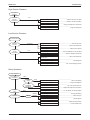
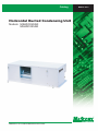
Horizontal Ducted Condensing Unit
Models: M5HDC020AR
M5HDC025AR
M5HDC-2010
M5HDC-2010
Table of Contents
Table of Contents
Nomenclature......................................................................................................................2
Indoor Unit......................................................................................................................2
Outdoor Unit...................................................................................................................3
Product Line-Up..............................................................................................................4
Features...............................................................................................................................6
Application Information......................................................................................................7
Operating Range............................................................................................................7
Refrigerant Circuit Diagram............................................................................................8
Controller........................................................................................................................9
Installation Guideline....................................................................................................11
Sound Data........................................................................................................................ 18
Sound Pressure Level................................................................................................. 18
NC Curve..................................................................................................................... 19
Engineering & Physical Data........................................................................................... 20
General Data............................................................................................................... 20
Component Data......................................................................................................... 21
Safety Devices............................................................................................................ 22
Performance Data............................................................................................................. 23
Calculation Steps......................................................................................................... 23
Performance Table....................................................................................................... 27
Outline and Dimension.................................................................................................... 29
Electrical Data................................................................................................................... 31
Wiring Diagram................................................................................................................. 32
Service and Maintenance................................................................................................ 33
Troubleshooting............................................................................................................... 35
Exploded View and Part List........................................................................................... 40
“McQuay” is a registered trademark of McQuay International. All rights reserved.
© 2010 McQuay International. All rights reserved throughout the world.
Bulletin illustrations cover the general appearance of McQuay International products at the time of publication.
We reserve the right to change design and construction specifications at any time without notice.
Nomenclature
M5HDC-2010
Nomenclature
Indoor
M
5
CC
020
Brand
M
: McQuay
Refrigerant
“ ”
4
5
: Omitted if R22
: R407C
: R410A
Model Name
CC
: Ceiling Concealed
Capacity Index
020
: 20,000 Btu/h
Chassis
C
: C series
Model Type
“ ”
R
2
: Omitted if cooling only
: Heatpump
C
R
Nomenclature
M5HDC-2010
Outdoor
M
5
HDC
020
A
R
Brand
M
: McQuay
Refrigerant
“ ”
4
5
: Omitted if R22
: R407C
: R410A
Model Name
HDC
: Horizontal Ducted Condensing Unit
Capacity Index
020
: 20,000 Btu/h
Chassis
A
: A series
Model Type
“ ”
R
: Omitted if cooling only
: Heatpump
3
Nomenclature
M5HDC-2010
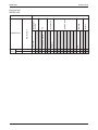
Product Line-Up
Indoor Unit
M5CC-CR
4
CE
EPS Drain Pan
Others
Air Filter
Marking
Air Purification
Refrigerant
Control
Bare
Fin
Handset
SLM 3
AFBA
AFAA
PCB
Heat 020CR
Pump 025CR
L2
M5CC-CR
Nomenclature
Classification
X
X
X
X
X
X
X
X
X
X
X
X
Hydrophilic Coated
Rotary
CE
Heat
Pump
Cap Tube
M5HDC-AR
020AR
AFBA
X
X
X
X
025AR
AFAA
X
X
X
X
Nomenclature
Others
Marking
Safety Devices
Compressor
Fin
Refrigerant
Control
M5HDC-2010
Product Line-Up
Outdoor Unit
M5HDC-AR
Classification
5
Features
M5HDC-2010
Features
Adequate External Static Pressure
The external static pressure is specially designed to blend in most of the interior design and yet to ensure a
sufficient heat transfer capability.
Aluminium Slit Fin
The unique slit fin on the heat exchanger greatly increases the heat transfer efficiency and thus boosts up the
unit capacity.
Short Piping
Reduce installation cost, improved reliability efficiency compared to roof mounted units.
Flexibility in Installation
The supply and return grille can be selected based on end user or professional interior designer in integrating
the HDC unit to their favorite interior design.
Invisible & Evergreen
To make your condensing unit invisible by installing it above the ceiling with only the supply and return grille
exposed to view. This ceiling concealed ducted condensing type of design has made it an “evergreen” design
without scarifying the previous floor space.
6
Application Information
M5HDC-2010
Application Information
Operating Range
Ensure the operating temperature is in allowable range.
Heatpump
Cooling
Heating
Outdoor temp. (°CDB)
46
35
STD
19
Outdoor temp. (°CWB)
18
6
STD
-9
24
15
Indoor temp. (°CWB)
15
21
27
Indoor temp. (°CDB)
Caution :
The use of your air conditioner
outside the range of working
temperature and humidity can
result in serious failure.
Note:
Standard Operating Range
7
Application Information
M5HDC-2010
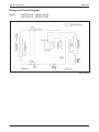
Refrigerant Circuit Diagram
Model:
M5CC020CR – M5HDC020AR
M5CC025CR – M5HDC025AR
70034 095378
8
Application Information
M5HDC-2010
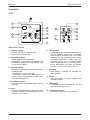
Controller
SLM
8
10
9
4
SENSOR
ON/OFF
AUTO
2
TEMP
HIGH
MED
TIMER
HEAT
MODE
3
SWING
ON/OFF
TEMP
7
FAN
LOW
5
DRY
1
FAN
2
COOL
FAN
4
1
SLEEP
6
6
SWING
SLEEP
TIMER
MODE
3
5
7
Operation Guide
1. “ON/OFF” switch
• Press to start the air conditioner unit.
• Press again to stop the unit.
2. Temperature setting
• Set the desired room temperature.
• Press button to increase or decrease the set
temperature. Setting range are between 16°C
to 30°C (60°F to 80°F).
3. Operation Modes
• Press the “mode” button for select the type of
operating mode.
- Cooling Only : COOL, DRY, FAN
- Heat Pump : AUTO, COOL, DRY, HEAT, FAN
(AUTO mode is represented by both COOL
and HEAT LED light on)
4. Fan Speed selection.
• Press the button until the desired fan speed is
achieved.
5. Timer.
• Press the set button to select the switch timer
of the air conditioner unit (the setting range is
between 1 to 10 hours).
6. “Sleep” mode
• Press button to activate the sleep function can
only be activated under “cool” or heating
mode operation. Activated under “cool” mode
operation, the set temperature will increase
0.5°C after 30minutes, 1°C after 1 hour and
2°C after 2hours. If it is actiaved under
“HEAT” mode operation, the set temperature
will be descreased 0.5°C after 30 minutes,
1°C after 1 hour and 2°C after 2 hours.
7. Air Swing
• Press button to activate the automatic air
swing function.
8. Sensor
• Infra red sensor to receive signals from
wireless controller.
9. LED Display
• To display the set temperature (in °C) and
timer delay setting (in hours).
10. Transmission source
• To transmit signals to the air conditioner.
9
Application Information
M5HDC-2010
Installation Guideline
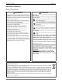
Safety Precautions
WARNING
• Installation and maintenance should be performed by
qualified persons who are familiar with local code and
regulation, and experienced with this type of appliance.
• All field wiring must be installed in accordance with the
national wiring regulation.
• Ensure that the rated voltage of the unit corresponds
to that of the name plate before commencing wiring
work according to the wiring diagram.
• The unit must be GROUNDED to prevent possible
hazard due to insulation failure.
• All electrical wiring must not touch the refrigerant
piping or any moving parts of the fan motors.
• Confirm that the unit has been switched OFF before
installing or servicing the unit.
• Disconnect from the main power supply before
servicing the air conditioner unit.
• DO NOT pull out the power cord when the power is
ON. This may cause serious electrical shocks which
may result in fire hazards.
• Keep the indoor and outdoor units, power cable and
transmission wiring, at least 1m from TVs and radios,
to prevent distorted pictures and static. {Depending on
the type and source of the electrical waves, static may
be heard even when more than 1m away}.
CAUTION
Please take note of the following important points
when installing.
• Do not install the unit where leakage of flammable
gas may occur.
If gas leaks and accumulates around the unit, it
may cause fire ignition.
• Ensure that drainage piping is connected properly.
If the drainage piping is not connected properly,
it may cause water leakage which will dampen
the furniture.
• Do not overcharge the unit.
This unit is factory pre-charged. Overcharge will
cause over-current or damage to the compressor.
• Ensure that the unit’s panel is closed after service
or installation.
Unsecured panels will cause the unit to operate
noisily.
• Sharp edges and coil surfaces are potential
locations which may cause injury hazards. Avoid
from being in contact with these places.
• Before turning off the power supply, set the remote
controller’s ON/OFF switch to the “OFF” position
to prevent the nuisance tripping of the unit. If this is
not done, the unit’s fans will start turning automatically
when power resumes, posing a hazard to service
personnel or the user.
• Do not operate any heating apparatus too close to the
air conditioner unit. This may cause the plastic panel to
melt or deform as a result of the excessive heat.
• Ensure the color of wires of the outdoor unit and
the terminal markings are same to the indoors
respectively.
• IMPORTANT : DO NOT INSTALL OR USE THE
• AIR CONDITIONER UNIT IN A LAUNDRY ROOM.
• Do not use joined and twisted wires for incoming
power supply.
NOTICE
Disposal requirements
Your air conditioning product is marked with this symbol. This means that electrical and electronic products
shall not be mixed with unsorted household waste.
Do not try to dismantle the system yourself: the dismantling of the air conditioning system, treatment of
the refrigerant, of oil and of other parts must be done by a qualified installer in accordance with relevant
local and national legislation. Air conditioners must be treated at a specialized treatment facility for re-use,
recycling and recovery. By ensuring this product is disposed of correctly, you will help to prevent potential
negative consequences for the environment and human health. Please contact the installer or local authority
for more information.
Batteries must be removed from the remote controller and disposed of separately in accordance with relevant
local and national legislation.
10
M5HDC-2010
Application Information
Caution
Sharp edges and coil surfaces are potential injury hazard. Avoid from contact with them.
Installation of Indoor Unit
For installation of indoor unit, please refer to the indoor unit technical manual.
Installation of Outdoor Unit
The outdoor unit has to be installed as per recommended installation clearance (Diagram A)
Make sure that the location is suitable for piping and drainage.
Precaution steps as below :
i) Use the hanging bracket supplied with the unit.
ii) Ensure the support is strong enough to withstand the weight of the unit.
iii)Incline the drain pipe as per diagram B. Do not install drain trap to the drain pipe, this is
to prevent blockage of drain pipe during heat mode when defrost is in operation.
iv)After completion of drain piping, confirm the drainage is good and there are no leaks.
Diagram A
Diagram B
11
Application Information
M5HDC-2010
Wiring
Wiring Electrical Connections
• Wiring regulations on wire diameters differ from country to country. Please refer to your
LOCAL ELECTRICAL CODES for field wiring rules. Be sure that installation comply with
such rules and regulations.
General Precautions
• Ensure that the rated voltage of the unit corresponds to the name plate before carrying
out proper wiring according to the wiring diagram.
• Provide a power outlet to be used exclusively for each unit. A power supply disconnect
and a circuit breaker for over-current protection should be provided in the exclusive line.
• The unit must be GROUNDED to prevent possible hazards due to insulation failures.
• All wiring must be firmly connected.
• All wiring must not touch the hot refrigerant piping, compressor or any moving parts of
fan motors.
Refrigerant Piping
Maximum Pipe Length And Maximum Number Of Bends
• When the pipe length becomes too long, both the capacity and reliability drop.
As the number of bends increases, system piping resistance to the refrigerant flow
increases, thus lowering the cooling capacity, and as the result the compressor may
become defective. Always choose the shortest path and follow the recommendation as
tabulated below:
Data
Model
Max. Length, L
Max. Elevation, H
Max. No. of Bends
M5HDC020AR
M5HDC025AR
15 m
8m
10
15 m
8m
10
M5HDC020AR
6.35 (1/4)
15.88 (5/8)
M5HDC025AR
9.52 (3/8)
15.88 (5/8)
Piping Sizes (Flare Connection Type)
• Piping sizes are as follows:
Model
Liquid (mm/in)
Suction (mm/in)
12
M5HDC-2010
Application Information
Piping Connection To The Units
• Align the center of the piping and sufficiently tighten the flare nut with fingers.
• Finally, tighten the flare nut with torque wrench until the wrench clicks.
• When tightening the flare nut with torque wrench, ensure the direction for tightening
follows the arrow on the wrench.
Pipe Size (mm/in)
6.35 (1/4)
Torque (nm)
18
9.53 (3/8)
42
15.88 (5/8)
65
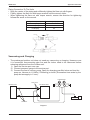
Vacuuming and Charging
• The precharged outdoor unit does not need any vacuuming or charging. However once
it is connected, theconnecting pipe line and the indoor need to be vacuumed before
releasing refrigerant from the outdoor unit.
1) Open the service port core cap.
2) Connect pressure gauge to the service port.
3) Connect the line to vacuum pump. Open the charging manifold valve and turn the pump on. Vacuum to -0.1MPa (-760mmHg) or lower. (Evacuation time varies by the pump but averagely in 1 hour).
CHARGE SET
Flare Valve
INDOOR UNIT
OUTDOOR UNIT
LO
HI
VACUUM PUMP
Flare Joint
Diagram 1
13
Application Information
M5HDC-2010
4) After evacuation, unscrew the spindle (diagram 2) for the gas to run to indoor unit.
Diagram 2
• The refrigerant gas has already charged into the outdoor unit. For the piping length of 5m.
Additional refrigerant charge after vacuuming is not necessary.
• When the piping length is more than 5m, please use the table below (unit in gram).
Model
M5HDC020AR
M5HDC025AR
7m
40
80
10m
100
200
15m
200
400
CHARGE SET
Flare Valve
INDOOR UNIT
OUTDOOR UNIT
Flare Joint
14
LO
HI
CHARGE
CYLINDER
M5HDC-2010
Application Information
Overall Checking
•
Ensure the following, in particular :1) The unit is mounted solidly and rigid in position.
2) Piping and connections are leak proof after charging.
3) Proper wiring has been done.
• Drainage check - pour some water into drain pan.
• Test run
1) Conduct a test run after water drainage test and gas leakage test.
2) Watch out for the following : a) Is the electric plug firmly inserted into the socket?
b) Is there any abnormal sound from unit?
c) Is there any abnormal vibrations with regard to unit itself or piping?
d) Is there smooth drainage of water?
•
Check that :1) Outdoor blower is running, with warm air blowing off the discharge grille (cooling cycle).
2) Indoor blower is running and discharge cool air (cooling cycle).
3) Suction (low side) pressure as recommended.
4) The remote controller incorporate a 3 minute delay in there circuit. Thus, it requires about 3minutes before the outdoor unit can start up.
Standard Operating Condition
Heatpump
Temperature
minimum indoor temperature
maximum indoor temperature
minimum outdoor temperature
maximum outdoor temperature
Ts °C
15
26.7
-2
24
Th °C
-3
18
Ts : Dry bulb temperature
Th : Wet bulb temperature
15
Application Information
M5HDC-2010
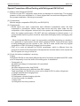
Special Precautions When Dealing with Refrigerant R410A Unit
(1)What is new refrigerant R410A?
R410A is a new HFC refrigerant which does not damage the ozone layer. The working
pressure of this new refrigerant is 1.6 times higher than conventional refrigerant (R22),
thus proper installation / servicing is essential.
(2)Components
Mixture weight composition R32(50%) and R125(50%)
(3)Characteristic
• R410A liquid and vapor components have different compositions when the fluid
evaporates or condenses. Hence, when leak occurs and only vapor leaks out, the
composition of the refrigerant mixture left in the system will change and subsequently
affect the system performance. DO NOT add new refrigerant to leaked system. It is
recommended that the system should be evacuated thoroughly before recharging with
R410A.
•When refrigerant R410A is used, the composition will differ depending on whether it
is in gaseous or liquid phase. Hence when charging R410A, ensure that only liquid
is being withdrawn from the cylinder or can. This is to make certain that only original
composition of R410A is being charged into the system.
• POE oil is used as lubricant for R410A compressor, which is different from the
mineral oil used for R22 compressor. Extra precaution must be taken not to expose the
R410A system too long to moist air.
(4)Check list before installation / servicing
Tubing
Refrigerant R410A is more easily affected by dust of moisture compared with R22, make
sure to temporarily cover the ends of the tubing prior to installation.
• Compressor oil
No additional charge of compressor oil is permitted.
• Refrigerant
No other refrigerant other that R410A
• Tool (size of service port is different from R22 system)
Tools specifically for R410A only (must not be used for R22 or other refrigerant)
i) Gauge manifold and charging hose
ii) Gas leak detector
iii) Refrigerant cylinder/charging cylinder
iv) Vacuum pump c/w adapter
v) Flare tools
vi) Refrigerant recovery machine
16
M5HDC-2010
Application Information
(5)Handling and installation guidelines
Like R22 system, the handling and installation of R410A system are closely similar.
All precautionary measures; such as ensuring no moisture, no dirt or chips in the
system, clean brazing using nitrogen, and thorough leak check and vacuuming are
equally important requirements. However, due to its hydroscopic POE oil, additional
precautions must be taken to ensure optimum and trouble free system operation.
(a)During installation or servicing, avoid prolong exposure of the internal part of the
refrigerant system to moist air. Residual POE oil in the piping and components can
absorb moisture from the air.
(b)Ensure that the compressor is not exposed to open air for more than the
recommended time specified by its manufacturer (typically less than 10 minutes).
Removed the seal plugs only when the compressor is about to be brazed.
(c) The system should be thoroughly vacuumed to 1.0 Pa (700mmHg) or lower.
This vacuuming level is more stringent than R22 system so as to ensure no
incompressible gas and moisture in the system.
17
Sound Data
M5HDC-2010
Sound Data
Sound Pressure Level
Ext. Static
Model
M5CC020CR
M5CC025CR
Speed
1/1 Octave A-Weighted Sound Pressure (dBA), ref 20µPa
(mmAq)
125Hz
6.5
High
42
6.0
Medium
41
3.5
Low
40
5.5
High
42
4.0
Medium
41
3.0
Low
36
250Hz
39
37
36
41
40
35
500Hz
36
34
32
37
36
33
1kHz
34
31
29
34
33
31
2kHz
28
26
23
31
29
26
4kHz
22
20
18
29
28
27
8kHz
17
15
13
23
22
21
Overall Noise
A (dBA) Criteria
38
33
36
30
34
27
40
33
39
32
36
30
Microphone position: 1.4m below the centre of the unit. (GB Standard- GB/ D17758)
Tested with 2m length duct at the discharge outlet and air return inlet.
Model
Measuring Location
2m length test duct
2m length test duct
Air
Test Unit
M5CC020CR
M5CC025CR
1.4m
Microphone
Standard: GB/D 17758
18
M5HDC-2010
Sound Data
M5CC020CR
NC Curve
70
Sound pressure level (dB, ref 20µPa)
60
50
NC- 5 0
NC- 4 5
40
NC- 4 0
High fan
30
NC- 3 5
Medium fan
NC- 3 0
Low fan
NC- 2 5
20
10
0
125
250
500
1000
2000
4000
8000
Octave-band frequency (Hz)
M5CC025CR
NC Curve
70
Sound pressure level (dB, ref 20µPa)
60
50
NC- 5 0
NC- 4 5
40
NC- 4 0
NC- 3 5
High fan
30
NC- 3 0
Medium fan
Low fan
20
NC- 2 5
NC- 2 0
10
0
125
250
500
1000
2000
4000
8000
Octave-band frequency (Hz)
19
Engineering and Physical Data
M5HDC-2010
Engineering And Physical Data
General Data - Heat Pump (R410A)
MODEL
INDOOR UNIT
M5CC020CR
M5CC025CR
M5HDC020AR
M5HDC025AR
Btu/h
18300
22300
W
5360
6540
Btu/h
18500
23500
W
5420
6890
OUTDOOR UNIT
NOMINAL COOLING CAPACITY
NOMINAL HEATING CAPACITY
NOMINAL TOTAL INPUT POWER (COOLING)
W
2350
2930
NOMINAL TOTAL INPUT POWER (HEATING)
W
2120
2720
NOMINAL RUNNING CURRENT (COOLING)
A
10.5
14
NOMINAL RUNNING CURRENT (HEATING)
A
9.9
13.2
V/Ph/Hz
220-240/1/50
220-240/1/50
W/W
2.35
2.23
R410A
R410A
OUTDOOR CAP. TUBE
OUTDOOR CAP. TUBE
POWER SOURCE
EER
REFRIGERANT TYPE
REFRIGERANT CONTROL (EXPANSION DEVICE)
CONTROL
INDOOR UNIT
AIR FLOW
AIR DISCHARGE
OPERATION
DUCTED
SLM WIRED HANDSET
SLM WIRED HANDSET
HIGH
l/s / CFM
330 / 700
345 / 730
MEDIUM
l/s / CFM
321 / 680
340 / 720
LOW
l/s / CFM
293 / 620
274 / 580
Pa / in.wg.
64 / 58 / 34 (0.3 / 0.2 / 0.1)
55 / 39 / 29 (0.2 / 0.2 / 0.1)
40 / 39 / 36
EXTERNAL STATIC PRESSURE (H/M/L)
dBA
38 / 36 / 34
HEIGHT
mm/in
261 / 10.3
261 / 10.3
WIDTH
mm/in
1065 / 41.9
1200 / 47.2
DEPTH
mm/in
376 / 14.8
411 / 16.2
HEIGHT
mm/in
376 / 14.8
376 / 14.8
WIDTH
mm/in
1251 / 49.3
1380 / 54.6
DEPTH
mm/in
541 / 21.3
541 / 21.3
UNIT WEIGHT
kg/lb
22 / 49
25 / 55
CONDENSATE DRAIN SIZE
mm/in
19.1 / 3/4
19.1 / 3/4
l/s / CFM
640 / 1346
600 / 1278
dBA
46
47
mm/in
mm/in
mm/in
mm/in
mm/in
mm/in
kg/lb
618 / 24.3
703 / 27.7
1347 / 53.0
618 / 24.3
703 / 27.7
1347 / 53.0
119 / 262
FLARE VALVE
6.4 / 1/4
12.7 / 1/2
1.395 / 3.08
618 / 24.3
703 / 27.7
1347 / 53.0
618 / 24.3
703 / 27.7
1347 / 53.0
122 / 269
FLARE VALVE
6.4 / 1/4
15.9 / 5/8
1.55 / 3.417
SOUND PRESSURE LEVEL (H/M/L)
UNIT DIMENSION
PACKING DIMENSION
AIR FLOW
SOUND PRESSURE LEVEL
OUTDOOR UNIT
DUCTED
UNIT DIMENSION
PACKING DIMENSION
HEIGHT
WIDTH
DEPTH
HEIGHT
WIDTH
DEPTH
UNIT WEIGHT
TYPE
PIPE CONNECTION
REFRIGERANT CHARGE
SIZE
LIQUID
GAS
mm/in
mm/in
kg/lb
1) ALL SPECIFICATIONS ARE SUBJECTED TO CHANGE BY THE MANUFACTURER WITHOUT PRIOR NOTICE.
2) ALL UNITS ARE BEING TESTED AND COMPLY TO ISO 5151.
3) NOMINAL COOLING AND HEATING CAPACITY ARE BASED ON THE CONDITIONS BELOW :
COOLING - 27°C DB / 19°C WB INDOOR AND 35°C DB / 24°C WB OUTDOOR
4) SOUND PRESSURE LEVEL ARE ACCORDING TO JIS B 8615 STANDARD. POSITION OF THE MEASUREMENT POINT IS 1m IN FRONT AND
1m BELOW THE UNIT.
20
M5HDC-2010
Engineering and Physical Data
Components Data (R22)
MODEL
INDOOR FAN
INDOOR FAN
MOTOR
INDOOR UNIT
M5CC020CR
M5CC025CR
OUTDOOR UNIT
M5HDC020AR
M5HDC025AR
TYPE
CENTRIFUGAL
CENTRIFUGAL
QUANTITY
2
2
MATERIAL
GALVANIZED STEEL
GALVANIZED STEEL
DRIVE
DIAMETER
mm/in
LENGTH
mm/in
TYPE
QUANTITY
INDEX OF PROTECTION (IP)
TYPE
OUTDOOR FAN
202 / 7.95
INDUCTION
1
1
N/A
N/A
CENTRIFUGAL (10" x8")
CENTRIFUGAL (10" x8")
1
MATERIAL
HOT DIP GALVANISED STEEL
HOT DIP GALVANISED STEEL
DIRECT
DIRECT
mm/in
TYPE
QUANTITY
INDEX OF PROTECTION (IP)
TYPE
OIL TYPE
OIL AMOUNT
cm3 / fl.oz.
MATERIAL
TUBE
INDOOR COIL
FIN
1
1
IP00
IP00
ROTARY
ROTARY
RB68A OR FREOL ALPHA68M
RB68A OR FREOL ALPHA68M
470 / 15.9
700 / 23.7
SEAMLESS INNER
GROOVE COPPER
SEAMLESS INNER
GROOVE COPPER
7.00 / 0.278
7.00 / 0.278
mm/in
0.28 / 0.011
0.28 / 0.011
ALUMINIUM (SLIT FIN)
ALUMINIUM (SLIT FIN)
THICKNESS
mm/in
0.11 / 0.0043
0.11 / 0.0043
FACE AREA
m2/ft2
0.176 / 1.892
0.203 / 2.187
ROW
3
3
FIN PER INCH
18
18
SEAMLESS COPPER TUBE
SEAMLESS COPPER TUBE
DIAMETER
mm/in
7.00 / 0.276
7.00 / 0.276
THICKNESS
mm/in
0.28 / 0.011
0.28 / 0.011
ALUMINIUM
ALUMINIUM
THICKNESS
mm/in
0.105 / 0.004
0.105 / 0.004
FACE AREA
m2/ft2
0.37 / 573.5
0.37 / 573.5
ROW
2
3
FIN PER INCH
19
19
WASHABLE SARANET
FILTER
WASHABLE SARANET
FILTER
TYPE
FILTER
SINGLE PHASE INDUCTION
mm/in
MATERIAL
OUTDOOR COIL
381 / 15
SINGLE PHASE INDUCTION
THICKNESS
MATERIAL
TUBE
380 / 15
DIAMETER
MATERIAL
FIN
AIR QUALITY
202 / 7.95
INDUCTION
1
DIAMETER
COMPRESSOR
DIRECT
160 / 6.30
QUANTITY
DRIVE
OUTDOOR FAN
MOTOR
DIRECT
160 / 6.30
pc
1
1
LENGTH
mm/in
860 / 33.88
995 / 39.17
WIDTH
mm/in
195 / 7.68
195 / 7.68
THICKNESS
mm/in
5 / 0.20
5 / 0.20
MATERIAL
GALVANIZED STEEL
GALVANIZED STEEL
QUANTITY
SIZE
INDOOR UNIT
CASING
OUTDOOR UNIT
FINISHING
WITH PE INSULATION
WITH PE INSULATION
COLOUR
WITHOUT POWDER PAINT
WITHOUT POWDER PAINT
MATERIAL
GALVANIZED STEEL
GALVANIZED STEEL
FINISHING
PAINTED
PAINTED
COLOUR
LIGHT GREY
LIGHT GREY
1) ALL SPECIFICATIONS ARE SUBJECTED TO CHANGE BY THE MANUFACTURER WITHOUT PRIOR NOTICE.
21
Engineering and Physical Data
M5HDC-2010
Safety Devices
MODEL
M5CC020CR
M5CC025CR
M5HDC020AR
M5HDC025AR
N/A
N/A
kPa / psi
N/A
N/A
kPa / psi
N/A
N/A
N/A
N/A
INDOOR UNIT
OUTDOOR UNIT
TYPE
HIGH PRESSURE SWITCH OPEN
CLOSE
SAFETY DEVICE
TYPE
LOW PRESSURE SWITCH
OPEN
kPa / psi
N/A
N/A
CLOSE
kPa / psi
N/A
N/A
N/A
N/A
N/A
N/A
PHASE SEQUENCER
DISCHARGE THERMOSTAT SETTING
°C / °F
1) ALL SPECIFICATIONS ARE SUBJECTED TO CHANGE BY THE MANUFACTURER WITHOUT PRIOR NOTICE.
22
Performance Data
M5HDC-2010
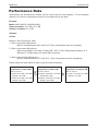
Performance Data
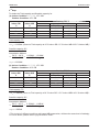
Interpolation and Extrapolation method can be used to get the total capacity, TC and sensible
capacity, SC at those temperatures which are not stated out in the table.
Example:
Model: M5CC020CR - M5HDC020AR
Indoor Condition: 23°C DB, 15°C WB
Outdoor Condition: 37°C DB
Solution:
Overall
Based on the Performance Table
1. Refer to the Indoor DB column,
- 23°C is located between 20°C and 24°C (Thus, Interpolation need to be applied)
2. Refer to the Indoor WB column,
- 15°C only available in the case of Indoor DB = 20°C. (Thus, Extrapolation between 16°C
WB and 17°C WB during 24°C indoor DB is required)
3. Refer to the Outdoor DB column,
- 37°C is located between 35°C and 40°C. (Thus, Interpolation need to be applied)
Please follow the steps below in order to get the required capacity.
1 st Step
Extrapolation of Indoor WB
2 nd Step
Interpolation of Indoor DB
3 rd Step
Interpolation of Outdoor DB
Find TC, SC for
(a) Indoor: 24°C DB, 15°C WB
Outdoor: 35°C DB
Find TC, SC for
(a) Indoor: 23°C DB, 15°C WB
Outdoor:35°C DB
Find TC, SC for
(a) Indoor: 23°C DB, 15°C WB
Outdoor: 37°C DB
(b) Indoor: 24°C DB, 15°C WB
Outdoor: 40°C DB
(b) Indoor: 23°C DB, 15°C WB
Outdoor: 40°C DB
23
Performance Data
M5HDC-2010
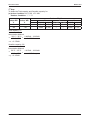
Calculation Steps
Details:
1st Step:
To obtain the Total capacity and Sensible capacity for
(a) Indoor Condition: 24°C DB, 15°C WB
Outdoor Condition: 35°C DB
24
15
16
17
Outdoor DB, ˚C
35
TC (kW)
SC (kW)
.......................
x1
3.363
3.431
.....
Indoor WB
˚C
.....
Indoor DB
˚C
y1
2.381
2.288
Total capacity, TC
⇒ x1 = 3.295kW (Same as Total capacity at 20°C Indoor DB / 15°C Indoor WB & 35°C Outdoor WB)*
Sensible capacity, SC
Extrapolation Method:
⇒
17º C – 15º C
2.288kW – y1
=
17º C – 16º C
2.228kW – 2.381kW
⇒ y1 = 2.474kW
(b) Indoor Condition: 24°C DB, 15°C WB
Outdoor Condition: 40°C DB
24
15
16
17
Outdoor DB, ˚C
40
TC (kW)
SC (kW)
........................
x2
3.066
3.137
.....
Indoor WB
˚C
.....
Indoor DB
˚C
y2
2.056
1.954
Total capacity, TC
⇒ x2 = 2.995kW (Same as Total capacity at 20°C Indoor DB / 15°C Indoor WB & 40°C Outdoor WB)*
Sensible capacity, SC
Extrapolation Method:
17º C – 15º C
1.954kW – y2
⇒
=
17º C – 16º C
1.954kW – 2.056kW
⇒ y2 = 2.158kW
* This is due to 2 different conditions with same WB temperature, will have the same level of enthalpy.
For more details, please refer to psychrometrics chart
24
M5HDC-2010
Performance Data
2 nd Step:
To obtain the Total capacity and Sensible capacity for
(a) Indoor Condition: 23°C DB, 15°C WB
Outdoor Condition: 35°C DB
20
23
24
15
15
15
........................
....
Outdoor DB,˚C
35
TC (kW)
SC (kW)
Indoor WB
˚C
....
Indoor DB
˚C
3.295
x3
3.295
1.510
y3
2.474
Total capacity, TC
⇒ x3 = 3.295kW (Same as Total capacity at 20°C Indoor DB / 15°C Indoor WB & 35°C Outdoor WB)*
Sensible capacity, SC
Interpolation Method:
24º C – 20º C
2.474kW – 1.510kW
⇒
=
24º C – 23º C
2.474kW – y3
⇒ y1 = 2.233kW
(b) Indoor Condition: 23°C DB, 15°C WB
Outdoor Condition: 40°C DB
20
23
24
15
15
15
.........................
2.995
x4
2.995
....
Outdoor DB,˚C
40
SC (kW)
TC (kW)
Indoor WB
˚C
....
Indoor DB
˚C
1.195
y4
2.158
Total capacity, TC
⇒ x4 = 2.995kW (Same as Total capacity at 20°C Indoor DB / 15°C Indoor WB & 40°C Outdoor WB)*
Sensible capacity, SC
Interpolation Method:
24º C – 20º C
2.158kW – 1.195kW
⇒
=
24º C – 23º C
2.158kW - y1
⇒ y2 = 1.597kW
* This is due to 2 different conditions with same WB temperature, will have the same level of enthalpy.
For more details, please refer to psychrometrics chart
25
Performance Data
M5HDC-2010
3 rd Step:
To obtain the Total capacity and Sensible capacity for
(a) Indoor Condition: 23°C DB, 15°C WB
Outdoor Condition: 37°C DB
2.233
x
y
Total capacity, TC
Interpolation Method:
40º C – 35º C
2.995kW – 3.295kW
⇒
=
40º C – 37ºC
2.995kW – x
⇒ x = 3.175kW
Sensible capacity, SC
Interpolation Method:
40º C – 35º C
1.917kW – 2.233kW
⇒
=
40º C – 37º C
1.917kW – y
⇒ y = 2.107kW
26
....
3.295
....
.............
....
15
....
23
....
Outdoor DB, ˚C
35
37
40
TC (kW) SC (kW) TC (kW) SC (kW) TC (kW) SC (kW)
Indoor WB
˚C
....
Indoor DB
˚C
2.995
1.917
M5HDC-2010
Performance Data
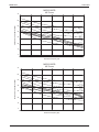
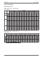
Performance Table
Heatpump (R410A)
Model: M5CC020CR - M5HDC020CR
Cooling Mode
Outdoor DB°C
20
ID DB°C ID WB°C
20
24
28
30
25
30
35
40
TC(kW)
SC(kW)
TC(kW)
SC(kW)
TC(kW)
SC(kW)
TC(kW)
SC(kW) TC(kW)
15
6.384
4.286
6.049
3.950
5.763
3.665
5.477
3.379
16
6.485
3.986
6.152
3.707
5.844
3.453
5.536
3.199
16
6.485
5.185
6.152
4.906
5.844
4.652
5.536
17
6.591
4.885
6.260
4.662
5.929
4.440
18
6.674
4.562
6.329
4.380
5.985
19
6.737
4.192
6.279
3.819
20
6.843
3.900
6.488
3.724
18
6.674
5.761
6.329
19
6.737
5.391
20
6.843
21
22
46
SC(kW)
TC(kW)
SC(kW)
5.191
3.093
4.848
2.750
5.227
2.945
4.857
2.640
4.398
5.227
4.144
4.857
3.839
5.598
4.218
5.267
3.996
4.870
3.729
4.199
5.640
4.018
5.295
3.836
4.882
3.619
5.821
3.445
5.363
3.072
5.150
3.270
4.894
3.508
6.133
3.547
5.778
3.370
5.423
3.193
4.997
2.981
5.579
5.985
5.398
5.640
5.217
5.295
5.035
4.882
4.818
6.279
5.018
5.821
4.644
5.363
4.271
5.150
4.469
4.894
4.707
5.099
6.488
4.923
6.133
4.746
5.778
4.569
5.423
4.392
4.997
4.180
6.929
4.761
6.577
4.548
6.225
4.335
5.874
4.122
5.522
3.909
5.100
3.653
7.015
4.423
6.667
4.173
6.318
3.924
5.969
3.675
5.621
3.425
5.202
3.126
23
7.101
4.084
6.756
3.799
6.410
3.513
6.065
3.227
5.720
2.942
5.305
2.599
24
7.188
3.746
6.845
3.424
6.503
3.102
6.161
2.780
5.819
2.458
5.408
2.072
20
6.843
5.699
6.488
5.522
6.133
5.345
5.778
5.169
5.423
4.992
4.997
4.780
21
6.929
5.361
6.577
5.148
6.225
4.934
5.874
4.721
5.522
4.508
5.100
4.253
22
7.015
5.022
6.667
4.773
6.318
4.523
5.969
4.274
5.621
4.025
5.202
3.725
23
7.101
4.684
6.756
4.398
6.410
4.112
6.065
3.827
5.720
3.541
5.305
3.198
24
7.188
4.345
6.845
4.023
6.503
3.702
6.161
3.380
5.819
3.058
5.408
2.671
Model: M5CC020CR - M5HDC020AR
Heating Mode
Outdoor WB°C
-9
ID DB°C
-6
-5
6
12
15
18
TC(kW) SC(kW) TC(kW) SC(kW) TC(kW) SC(kW) TC(kW) SC(kW) TC(kW) SC(kW) TC(kW) SC(kW) TC(kW) SC(kW)
15
3.278
3.278
3.710
3.710
3.854
3.854
5.438
5.438
6.302
6.302
6.735
6.735
7.167
7.167
17
3.192
3.192
3.949
3.949
3.777
3.777
5.432
5.432
6.266
6.266
6.705
6.705
7.145
7.145
19
3.106
3.106
4.189
4.189
3.701
3.701
5.425
5.425
6.230
6.230
6.676
6.676
7.122
7.122
21
3.020
3.020
4.155
4.155
3.624
3.624
5.381
5.381
6.194
6.194
6.647
6.647
7.100
7.100
23
2.934
2.934
3.849
3.849
3.548
3.548
5.299
5.299
6.157
6.157
6.618
6.618
7.078
7.078
25
2.848
2.848
3.543
3.543
3.472
3.472
5.217
5.217
6.121
6.121
6.589
6.589
7.056
7.056
27
2.762
2.762
3.237
3.237
3.395
3.395
5.135
5.135
6.085
6.085
6.559
6.559
7.034
7.034
FROST REGION
27
Performance Data
M5HDC-2010
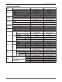
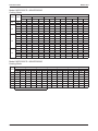
Model: M5CC025CR - M5HDC025AR
Cooling Mode
Outdoor DB°C
20
ID DB°C ID WB°C
20
24
28
30
25
30
35
40
46
TC(kW)
SC(kW)
TC(kW)
SC(kW)
TC(kW)
SC(kW)
TC(kW)
SC(kW)
TC(kW)
SC(kW)
TC(kW)
15
6.379
4.076
5.976
3.673
5.606
3.303
5.235
2.933
4.865
2.562
4.420
SC(kW)
2.118
16
6.656
3.828
6.268
3.467
5.897
3.122
5.525
2.777
5.153
2.431
4.707
2.017
16
6.656
5.144
6.268
4.782
5.897
4.437
5.525
4.092
5.153
3.747
4.707
3.333
17
6.934
4.896
6.561
4.576
6.188
4.256
5.815
3.936
5.441
3.616
4.994
3.233
18
7.197
4.633
6.828
4.344
6.460
4.055
6.091
3.767
5.723
3.478
5.280
3.132
19
7.470
4.370
7.158
4.115
6.846
3.861
6.534
3.606
6.094
3.345
5.567
3.032
20
7.716
4.092
7.325
3.796
6.934
3.499
6.543
3.203
6.153
2.907
5.684
2.551
18
7.197
5.948
6.828
5.660
6.460
5.371
6.091
5.083
5.723
4.794
5.280
4.448
19
7.470
5.686
7.158
5.431
6.846
5.177
6.534
4.922
6.094
4.661
5.567
4.347
20
7.716
5.408
7.325
5.112
6.934
4.815
6.543
4.519
6.153
4.222
5.684
3.867
21
7.972
5.131
7.554
4.795
7.137
4.460
6.719
4.124
6.302
3.789
5.801
3.386
22
8.228
4.853
7.784
4.479
7.339
4.104
6.895
3.730
6.451
3.355
5.918
2.906
23
8.484
4.576
8.013
4.162
7.542
3.749
7.071
3.335
6.600
2.921
6.035
2.425
24
8.741
4.299
8.243
3.846
7.745
3.393
7.247
2.940
6.749
2.488
6.151
1.944
20
7.325
5.769
6.934
5.473
6.543
5.177
6.153
4.880
5.684
4.525
7.716
6.066
21
7.972
5.789
7.554
5.453
7.137
5.118
6.719
4.782
6.302
4.447
5.801
4.044
22
8.228
5.511
7.784
5.137
7.339
4.762
6.895
4.388
6.451
4.013
5.918
3.564
23
8.484
5.234
8.013
4.820
7.542
4.407
7.071
3.993
6.600
3.579
6.035
3.083
24
8.741
4.957
8.243
4.504
7.745
4.051
7.247
3.598
6.749
3.146
6.151
2.602
Model: M5CC025CR - M5HDC025AR
Heating Mode
Outdoor WB°C
-9
ID DB°C
-6
-5
6
12
15
18
TC(kW) SC(kW) TC(kW) SC(kW) TC(kW) SC(kW) TC(kW) SC(kW) TC(kW) SC(kW) TC(kW) SC(kW) TC(kW) SC(kW)
15
4.164
4.164
4.713
4.713
4.895
4.895
6.908
6.908
8.006
8.006
8.555
8.555
9.104
9.104
17
4.054
4.054
4.551
4.551
4.766
4.766
6.900
6.900
7.789
7.789
8.323
8.323
8.856
8.856
19
3.945
3.945
4.389
4.389
4.636
4.636
6.892
6.892
7.573
7.573
8.091
8.091
8.609
8.609
21
3.836
3.836
4.259
4.259
4.507
4.507
6.731
6.731
7.356
7.356
7.859
7.859
8.362
8.362
23
3.727
3.727
4.161
4.161
4.377
4.377
6.418
6.418
7.140
7.140
7.627
7.627
8.115
8.115
25
3.618
3.618
4.064
4.064
4.247
4.247
6.106
6.106
6.923
6.923
7.395
7.395
7.867
7.867
27
3.509
3.509
3.966
3.966
4.118
4.118
5.793
5.793
6.707
6.707
7.163
7.163
7.620
7.620
FROST REGION
28
M5HDC-2010
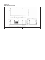
Outline and Dimension
Outline and Dimension
Indoor Unit
Model: M5CC020/ 025CR
Note: Dimension in mm
Model
M5CC020CR
M5CC025CR
A
1041
1176
B
225
225
C
1002
1137
D
962
1097
E
261
261
F
411
411
G
351
351
H
1065
1200
29
Outline and Dimension
M5HDC-2010
Outdoor Unit
Model: M5HDC020/ 025AR
Note: Dimension in mm
30
M5HDC-2010
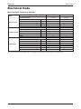
Electrical Data
Electrical Data
Electrical Data - Heatpump (R410A)
MODEL
INDOOR UNIT
OUTDOOR UNIT
INSULATION GRADE
POWER SOURCE
INDOOR MOTOR
V/Ph/Hz
CLASS E
CLASS E
220 240/1/50
220 - 240/1/50
RATED INPUT POWER
W
135
152
A
0.60
0.67
MOTOR OUTPUT
W
80
100
INSULATION GRADE
4
4
CLASS F
CLASS F
V/Ph/Hz
220-240/1/50
220-240/1/50
RATED INPUT POWER
W
409.7
383.4
RATED RUNNING CURRENT
A
1.87
1.77
MOTOR OUTPUT
W
375
375
POLES
6
6
INSULATION GRADE
-
220-240/1/50
POWER SOURCE
V/Ph/Hz
220-240/1/50
CAPACITOR
µF
50.0
45.0
RATED INPUT POWER (COOLING)
W
1803
2415
RATED INPUT POWER (HEATING)
W
1573
2205
RATED RUNNING CURRENT (COOLING)
A
8.1
12.0
RATED RUNNING CURRENT (HEATING)
A
7.5
10.9
LOCKED ROTOR AMP.
A
-
-
POWER SOURCE
COMPRESSOR
M5CC025CR
M5HDC025AR
RATED RUNNING CURRENT
POLES
OUTDOOR MOTOR
M5CC020CR
M5HDC020AR
1) ALL SPECIFICATIONS ARE SUBJECTED TO CHANGE BY THE MANUFACTURER WITHOUT PRIOR NOTICE
31
Wiring Diagram
M5HDC-2010
Wiring Diagram
Heat Pump
Indoor Unit
Outdoor Unit
Model: M5CC020CR
Model: M5HDC020AR
M5CC025CR M5HDC025AR
70034 095382
32
M5HDC-2010
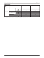
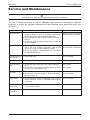
Service and Maintenance
Service and Maintenance
Caution
Disconnect From Main Supply Before Servicing The Air Conditioner
The unit is designed to give a long life operation with minimum maintenance required.
However, it should be regularly checked and the following items should be given due
attention.
Components
Maintenance Procedure
Recommended Schedule
Indoor Air Filter
1. Remove any dust adhering on the filter by using
avacuum cleaner or wash in lukewarm water (below
40°C/104°F) with a neutral cleaning detergent.
2. Rinse the filter well and dry before placing it back on to
the unit.
3. Do not use gasoline, volatile substances or chemicals
to clean the filter.
At least once every 2 weeks.
More frequently if necessary
Indoor Unit
1. Clean any dirt or dust on the grille or panel by wiping it
with a soft cloth soaked in lukewarm water (below
40°C/104°F) and a neutral detergent solution.
2. Do not use gasoline, volatile substances or chemicals
to clean the indoor unit.
At least once every 2 weeks.
More frequently if necessary
Condensate Drain 1. Check and clean.
Pan and Pipe
Every 3 months.
Indoor Fan
1. Check for unusual noise.
As necessary.
Indoor/Outdoor
Coil
1. Check and remove dirt which are clogged between
fins.
2. Check and remove obstacles which hinder air flow
in and out of indoor/outdoor unit.
Every month.
Electrical
1. Check voltage, current and wiring.
2. Check faulty contacts caused by loose connections,
foreign matters, etc.
Every 2 months.
Every 2 months.
Compressor
1. No maintenance needed if refrigerant circuit remains
sealed. However, check for refrigerant leak at joints
and fittings.
Every 6 months.
Compressor
Lubrication
1. Oil is factory charged. Not necessary to add oil if
circuit remains sealed.
No maintenance required.
Fan Motors
Lubrication
1. All motors pre-lubricated and sealed at factory.
No maintenance required.
Every month.
33
Service and Maintenance
M5HDC-2010
Pre Start Up Maintenance
(After Extended Shut Down)
- Inspect thoroughly and clean indoor and outdoor units.
- Clean or replace air filters.
- Clean condensate drain line.
- Clean clogged indoor and outdoor coils.
- Check fan imbalance before operation.
- Tighten all wiring connections and panels.
- Check for refrigerant leakage.
Most of the parts are accessible by removal of bottom & side panel.
Caution
• Do not charge OXYGEN, ACETYLENE OR OTHER FLAMMABLE and poisonous gases into the unit when
performing a leakage test or an airtight test. These gases could cause severe explosion and damage if
exposed to high temperature and pressure.
• It is recommended that only nitrogen or refrigerant be charged when performing the leakage or airtight test.
34
M5HDC-2010
Troubleshooting
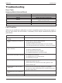
Troubleshooting
Error Code
Heatpump Model (Universal Board)
Error Code at 7 Segment Display
Blink E1
Blink E2
Blink E3
Blink E4
Blink E5
Blink E6
Blink Heat LED
Operation / Faulty Indication
Room sensor contact loose / short
Indoor coil sensor contact loose
Outdoor coil sensor contact loose
Compressor overload / Indoor coil sensor short /
Outdoor coil sensor short
Gas leak
N/A
Outdoor defrost (for Heatpump ony)
Fault Condition
When any air-conditioner malfunction is noted, immediately switch off the power supply to
the unit, and contact the local dealer, if necessary. Some simple troubleshooting tips are
given below :
Fault
Cause
1. Fan does not work 3 minutes after
starting
• Protection against the frequent starting. Wait 3 or 4 minutes.
2. The air conditioning unit does not
work
• Power failure or need to replace the fuse.
• The power plug is disconnected.
• Possibility of making a programming error in the controller.
• If the fault persist after these verifications, contact your installer.
3. The air conditioning unit does not
blow sufficiently
• The air filter is dirty.
• The doors or windows are open.
• The air entrance and exit are clogged.
• The regulate temperature is not high enough.
4. The remote control light is deficient
• The batteries are discharge.
• The batteries are not correctly inserted.
• The assembly is not good.
5. Air discharge flow has a bad odor
• This odor can be caused by cigarette smoke particles, perfume,
sweat, which stick to the coil.
• Check if there is any moisture on the walls, garment, other.
• Check the drain pan.
6. Condensation on the air grille of
indoor unit
• This is due to air humidity after a long time of operation.
• The unit has a lower temperature point, increase the point and
operate at high speed.
7. The water flow of air conditioning
unit
• Check the condensate evacuation.
8. The air conditioning unit are noisy
• “Air flow noise” : refrigerant fluid admission in evaporator.
35
Troubleshooting
M5HDC-2010
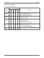
Diagnostic Guidelines
By means of pressure reading:
Probable cause
Too high
A little high
Normal
Circuit
A little low
Data
Too low
Pressure
High side
Low side
1.
2.
3.
4.
Overcharged with refrigerant.
Non-condensable gases in refrigerant circuit (e.g. air)
Obstructed air-intake / discharge.
Hot air short circuiting in outdoor unit.
High side
Low side
1. Poor compression / no compression
(compressor defective)
2. Reversing valve leaking.
High side
Low side
1.
2.
3.
4.
5.
6.
Undercharged with refrigerant.
Refrigerant leakage.
Air filter clogged / dirty (indoor unit).
Indoor fan locked / seized.
Defective defrost control, outdoor coil freeze up (heating).
Outdoor fan locked / seized (heating).
High side
Low side
1.
2.
3.
4.
5.
Outdoor fan blocked (cooling).
Outdoor coil dirty (cooling).
Indoor fan locked / seized (heating).
Indoor air filter clogged / dirty (heating).
Non-condensable gases in refrigerant circuit (e.g. air)
High side
Low side
1. Air intake temperature of indoor unit too high.
By Means Of Diagnosis Flow Chart
Generally, there are two kinds of troubles, i.e. starting failure and insufficient cooling / heating.
“Starting Failure” iscaused by electrical defect while “Insufficient Cooling / Heating” is caused
by improper application or defects inrefrigerant circuit.
No Cooling / Heating
Unit fail to start
Check power supply
- voltage
- phase
- frequency
Check settings of remote control box
Check power source cord
Check circuit breake & fuse
Fan fails to start
Compressor fails to start
Fan Motor Capacitor defective
Thermostat setting too high
Loose Connections,
Contactors
Protection Device Actuated
Irregular motor resistance ( Ω )
& insulation (M Ω )
Replace Fan Motor
Reset
Regular but fails
to start
Compressor locked (to replace compressor)
36
Voltage supply not within range
Loose Connections,
Improper wiring
Compressor
Capacitor Defective
Check motor resistance ( Ω ) and insulation (M Ω )
Irregular
Compressor Motor damaged ( to replace compressor)
M5HDC-2010
Troubleshooting
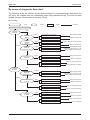
By means of diagnostic flow chart:
The following chart are efficient checking procedures for troubleshooting when these fan
coil units, are coupled with the condensing units using standard wiring. For dual circuited
models, perform the procedures for each circuit.
No Cooling
: Faulty
: Check
: Cause
: Remedy
No Cooling ( Compresor Does Not Start )
Evaporator
Fan Motor
Stop
Unit Power
Supply
Running
Faulty
Fuse For
Operation
Circuit
Blown
Overcurrent
Relay For
Evaporator Fan
Tripped
Evaporator Fan
Contactor
No Voltage or Low Voltage
Get The Right Voltage
Single Phase
Repait The Power Line
Components Shorted
Connections Loose
High or Low Voltage
Single Phase
Faulty
Coil Burnt
Contact Faulty
Faulty Fan Motor
Defective Operation Switch
Condenser
Fan Motor
Repair or Replace The Components
Tighten The Connections
Get The Right Voltage
Check The Power Supply To The
Motor : Repair When Necessary
Change The Contactor
Repair The Contacts
Repair Or Change The Motor
Repair Or Replace The Switch
Stop
Overcurrent
Relay For
Condenser Fan
Tripped
High Voltage or Low Voltage
Single Phase
Get The Right Voltage
Check The Power Supply To The
Motor : Repair When Necessary
Running
Condenser Fan
Contactor
Faulty
Coil Burnt
Contact Faulty
Fan Motor Faulty
Other Electrical Component Faulty
Compressor
Contactor
Faulty
Coil Burnt
Contact Faulty
Open Compressor Windings
Incorrect Wiring
Change The Contactor
Change The Contacts
Repair or Change The Motor
Repair or Change If Necessary
Change The Contactor
Change The Contacts
Change The Compressor
Correct The Wiring
37
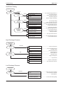
Troubleshooting
M5HDC-2010
Insufficient Cooling
Insufficient Cooling
Compressor
Cycling
Cycling On
Dual Pressure
Switch
Running
Overcurrent
Relay For
Compressor
Discharge Gas
Thermostat or
Internal
Thermostat
Tripping
Tripping
Tripping
High Discharge Pressure or Low
Suction Pressure
........... See "High Discharge Pressure" or
Clogged Capillary or Pressure
Switch
...............
"Low Suction Pressure"
Repair Clogging and Replace
The Switch If Required
Switch Faulty
...........
High Voltage or Low Voltage
...................
Single-Phase
.......
High Discharge Pressure And
High Suction Pressure
.............. See "High Discharge Pressure"
Loose Connections
.................... Tighten The Connections
High Discharge Pressure And
Low Suction Pressure
Discharge Pressure"
.............. See "High
or "Low Suction Pressure"
Refrigerant Short Charge or
Refrigerant Leakage
Refrigerant. Repair
..................... AddLeakage
If Detected.
High Suction Pressure
................ See "High Suction Pressure"
High Discharge Pressure or Low
Suction Pressure
Discharge Pressure"
.............. See "High
or "Low Suction Pressure"
Repair or Change If Necessary
Get The Right Voltage
Check The Power Line To The
Compressor : Repair When Necessary
or "High Suction Pressure"
High Discharge Pressure
High Discharge
Pressure
Condenser
Air Flow
Condenser
Air Inlet
Temperature
Restricted
High
Clogged Condenser Coil
...................... Clean The Condenser
Low Fan Speed
................ Check The Voltage And Get
Malfunction Of Fan Cycling
System
.....................Check The System And
Circulating Air Flow
.........................
Overcharged Refrigerant
.....................
Non-Condensable Gas
............................ Purge The Gas
Restricted Liquid Line
.................... Remove The Restriction
High Suction Pressure
............... See "High Suction Pressure"
The Right Voltage
Repair If Required
Secure Space For
Required Air Flow
Purge The Refrigerant
Low Discharge Pressure
Low Discharge
Pressure
Condenser
Air Flow
38
Excessive
Malfunction Of Fan Cycling
System
The System And Repair
................ Check
The Components If Required
Low Refrigerant Charge
.............................. Add Refrigerant
Low Ambient Temperature
................. See The Unit Working Range
Troubleshooting
M5HDC-2010
High Suction Pressure
High Suction
Pressure
Low
Evaporator
Air Inlet
Temperature
Defective Compressor Valve
................. Reduce The Fresh Air Intake
................ Reinforce The Duct Insulation
.......... Change Or Repair The Compressor
Overcharged Refrigerant
......................
Excessive Fresh Air Intake
Insufficient Duct Insulation
Purge The Refrigerant
Low Suction Pressure
Low Suction Pressure
Evaporator
Air Flow
Restricted
Evaporator
Air Inlet
Temperature
Restricted Duct
........................... Clean The Air Filter
...................... Remove The Restriction
Low Fan Speed
........................ Adjust The Fan Speed
Clogged Air Filter
Low
Short Cycling
Faulty Thermostat
.......... Remove Obstacles To Air Circulation
............... Repair Or Replace If Necessary
Restricted Liquid LIne And
Suction Line
...................... Remove The Restriction
Low Refrigerant Charge
.............................. Add Refrigerant
Low Discharge Pressure
................ See "Low Discharge Pressure"
Noisy Operation
Noisy Operation
Compressor
Noisy
Shipping
Bolt(s)
Noisy
Liquid
Refrigerant
Backing Up
Evaporator
Fan
Liquid Line
Noisy
Noisy
Strainer
Whistling
Overcharged Refrigerant
......................... Remove The Bolt(s)
....................... Purge The Refrigerant
Low Suction Pressure
................. See "Low Suction Pressure"
Worn Compressor Parts
......... Replace Or Repair The Compressor
Knocking Runner
.......... Fix The Runner Or Casing Properly
Unremoved Shipping Bolt(s)
Worn Bearing
Partially Clogged
Refrigerant Short Charge
Loose Fixed Screws
Inadequate Duct Work
........................ Change The Bearing
.............................Clean The Dryer
............................. Add Refrigerant
.....................Tighten All Fixed Screws
........................ Check Flexible Ducts
39
Exploded View and Part List
M5HDC-2010
Exploded View and Part List
Indoor Unit
Model: M5CC020/ 025CR
No
1
2
3
4
5
6
Description
Cabinet
M5CC020CR
M5CC025CR
Fan Deck
M5CC020CR
M5CC025CR
Assy. Coil
M5CC020C
M5CC025CR
Primary Drain Pan
M5CC020CR
M5CC025CR
Secondary Drain Pan
M5CC020C
M5CC025C
Hanger
Part No
R01013034005
R01013032362
R50014035082
R50014032629
R50024079268
R50024079271
R50063033908
R50063032369
R50019009407
R50017009420
R01014032372
No
Description
7
Parts not in diagram
Assy. Wheel & Housing - Left
A
Assy. Wheel & Housing - Right
B
Fan Motor
C
M5CC020CR
M5CC025CR
Air Filter
D
M5CC020CR
M5CC025CR
Assy. Drain Pipie Joint
E
L2 Control Module
F
M5CC020CR
M5CC025CR
SLM Handset
G
Part No
R50039005356
R50039005355
R03039004898
R03039004899
R03084037809
R03084037812
R50094035451
R04089028159
R04089018158
R04089011752
Note: All exploded view and part list are subjected to change by the manufacturer without prior notice
40
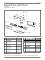
Exploded View and Part List
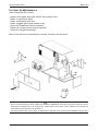
M5HDC-2010
Outdoor Unit
Model: M5HDC020AR
70014072757
No
Description
No
Description
1
Assy. Front Panel
12
Assy. 4-Way Valve
2
Assy. Drain Pan
13
Tube (Comp. Suct. To Acc. Out)
3
Assy. Base Panel
14
Blower
4
Assy. Coil
15
Fan Motor
5
Compressor Jacket
16
Bracket, Fan Motor
6
Hanging Bracket
17
Top Panel
7
Back Panel
18
Duct, Flange
8
Compressor
19
Service Panel
9
Assy. Flare Valve, 1/2"
20
Terminal Box
10
Assy. 2-Way Valve, 1/4"
21
Terminal Box Cover
11
Accumulator
Note: All exploded view and part list are subjected to change by the manufacturer without prior notice
41
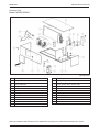
Exploded View and Part List
M5HDC-2010
Outdoor Unit
Model: M5HDC025AR
70014072758
No
Description
No
Description
1
Assy. Front Panel
12
Assy. 4-Way Valve
2
Assy. Drain Pan
13
Tube (Comp. Suct. To Acc. Out)
3
Assy. Base Panel
14
Blower
4
Assy. Coil
15
Fan Motor
5
Compressor Jacket
16
Bracket, Fan Motor
6
Hanging Bracket
17
Top Panel
7
Back Panel
18
Duct, Flange
8
Compressor
19
Service Panel
9
Assy. Flare Valve, 5/8"
20
Terminal Box
10
Assy. 2-Way Valve, 1/4"
21
Terminal Box Cover
11
Accumulator
Note: All exploded view and part list are subjected to change by the manufacturer without prior notice
42
Products manufactured in an ISO certified facility.
This document contains the most current product information as of this printing. For the
most up-to-date product information, please go to www.mcquay.com.
© 2010 McQuay International
www.mcquay.com