1
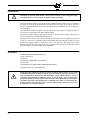
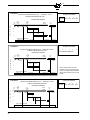
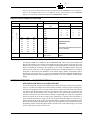
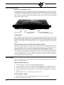
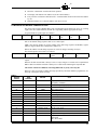
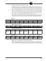
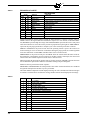
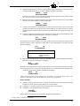
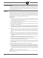
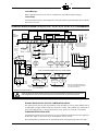
EP-1601 JANUARY 2004 ® FIREYE EP160, EP161, EP163, EP165, EP166, EP170 and EP174 PROGRAMMER MODULES WITH SELECTABLE OPERATION APPROVED DESCRIPTION The Fireye EP160, EP161 (extended MTFI), EP163 (programmable), EP170 and EP174 (early spark termination), or EP165, EP166 (pilot stabilization) programmer modules are used with the FLAMEMONITOR Burner Management Control System (P/N’s E100 and E110). Several operational characteristics of the programmer are determined by six (6) dipswitches located on the side of the programmer. These characteristics include forced blower motor start delay (dipswitch 1), extended purge timing (dipswitches 3, 4, 5) and the option requiring the 3-P running interlock circuit to be proven open at the start of the operating cycle (dipswitch 6). Dipswitch 2 is inactive. Model EP163 characteristics are programmed via the ED510 Display Module, rather than by dipswitch. The EP160, EP161, EP163, EP165, EP166, EP170 and EP174 programmers provide start-up programming, safe-start check, and flame monitoring supervision. They insure open damper (high purge) prepurge, proof of low fire position, and fuel valve end switch safety checks. A running interlock circuit on the FLAME-MONITOR system constantly monitors the limit switches, air flow switches, and fuel pressure switches through the programmer. The programmer control is designed to initiate a safety lockout if any of these circuits are open at the improper point in the control cycle. The programmer module will de-energize all fuel valve circuits within four (4) seconds (max.) following a flame failure [two (2) seconds for the EP165 and EP166], or at the end of the pilot trial for ignition period if no flame is detected. An alarm circuit will be energized following a safety lockout. The programmer module includes an RJ45 style connector to interface with an integral or remote alpha-numeric display (P/N ED510). It is also backward compatible with the ED500 display. It includes two (2) additional RJ style connectors to connect to an E500 communication interface in a multi-drop configuration or allow communication via a Modbus protocol. The programmer will also communicate with the E500 via the ED550 cables to provide backward compatibility. The programmer is the heart of the FLAME-MONITOR System and features a plug-in design for ease of installation. It is micro-processor based and stores the burner cycles, burner hours, system hours, and lockout history (with burner cycle and burner hour time stamp) which are accessible via the ED510 alpha-numeric display, E500 Communication Interface, InTouch Wireless Monitoring System or Modbus communications. If replaced, the new programmer card will begin accumulating a new history. Refer to Bulletin E-1101 for detailed information on the FLAME-MONITOR System. 1 INSTALLATION CAUTION: To prevent shock hazard, remove power from the system wiring base before proceeding. Remove control from the wiring base before proceeding. The EP programmer modules are used with the Fireye EB700 and E110 chassis. They are installed in the chassis by inserting the EP programmer module into the second slot on the control. This slot is marked “Programmer Module” on the side of the chassis. Refer to bulletin E-1101 for complete system information. The programmer module is designed to fit only in the proper slot. It cannot be snapped into place if inserted in the wrong location. DO NOT FORCE THEM. An amplifier module, display module ED510 (ED500 is obsolete), flame scanner, and wiring base are also required for the FLAME-MONITOR control. The EP160, EP161, EP165, EP166, EP170 and EP174 programmers with an Engineering code of 28 or later (e.g. 9414-28) are compatible with both the ED500 and ED510 display modules. See “Programmer and Display Module Compatibility” later in this document. The Engineering code is located on the back side of the board in the lower right hand corner. The EP163 programmer requires the ED510 display for initial configuration programming. APPROVALS UNDERWRITERS LABORATORIES INC. Listed: Guide MCCZ File MP1537 CANADIAN STANDARDS ASSOCIATION File #LR7989 ACCEPTABLE BY: INDUSTRIAL RISK INSURERS (I.R.I.) FACTORY MUTUAL (FM) APPROVED WARNING: This equipment generates, uses and can radiate radio frequency energy, and if not installed and used in accordance with the instruction manual, may cause interference to radio communications. It has been tested and found to comply with the limits for a Class A computing device pursuant to Subpart J of Part 15 of FCC Rules, which are designed to provide reasonable protection against such interference when operated in a commercial environment. Operation of this equipment in a residential area is likely to cause interference, in which case the user, at his own expense, will be required to take whatever measures may be required to correct the interference. 2 ORDERING INFORMATION IGNITION TIMING PURGE1 PART NUMBER 30 Sec. 1 EP160 30 Sec. 1 EP161 40 Sec. 5 EP163 30 Sec. 1 EP165 4 30 Sec. 1 EP1664 EP170 30 Sec. 1 EP1746 PTFI MTFI Term 5 10 Sec. 10 Sec. Term 6 10 Sec. 15 Sec. Term 5 10 Sec. 10 Sec. Term 6 10 Sec. 30 Sec. Term 5 5 Sec. 5 5 Sec. 5 Term 6 5 Sec. 5 5 Sec. 5 Term 5 10 Sec. — Term 6 10 Sec. 10 Sec. 3 Term 5 10 Sec. — Term 6 10 Sec. 15 Sec. 3 Term 5 5 Sec. — Term 6 10 Sec. 10 Sec. FFRT 2 4 Sec. 4 Sec. 4 Sec. 2 Sec. 2 Sec. 4 Sec. 1 2 3 Purge timings are adjustable. See “Dipswitches — Purge Timing.” FFRT is the Flame Failure Response Time. During MTFI, terminal 6 is energized for 5 seconds (pilot stabilization) before energizing terminal 7 for 10 seconds (EP165) or 15 seconds (EP166). 4 EP 165 and EP166 will lockout in the event of a power interruption. 5 EP163 purge and ignition timings are programmable via ED510. 6 M-D Low Fire start is proven closed during PTFI and MTFI. Note: EP160, EP161, EP163, EP165, EP166, EP170 and EP174 have non-recycle running interlock circuits (3/P). WARNING: While all controls are mechanically interchangeable because they mate with a common wiring base, you must select the correct model for your application. Inappropriate application of a control could result in an unsafe condition hazardous to life and property. TIMING CHARTS TYPE EP160 DIPSWITCH SETTINGS NON-RECYCLE RUNNING INTERLOCKS (3/P) PURGE TIME - 30 SEC.* FLAME FAILURE RESPONSE TIME 4 SEC. 1 2 3 4 5 6 INACTIVE Down Down Down Down PROGRAMMING SEQUENCE LFS CLOSED (MD) HFS L1/13 CLOSED ON (D8) T E R M I N A L S FIRING PERIOD L1/13 OFF M PURGE 30 SEC 5 POST PURGE 15 SEC MIN 30 SEC PTFI 10 SEC MTFI 10 SEC 6 MTFI 15 SEC 7 (MODULATOR MOTOR CIRCUIT) HIGH (10-X) LOW (10-12) AUTO (10-11) LOW (10-12) * Purge timings are adjustable. 3 TYPE EP161 DIPSWITCH SETTINGS NON-RECYCLE RUNNING INTERLOCKS (3/P) PURGE TIME - 30 SEC.* FLAME FAILURE RESPONSE TIME 4 SEC. 1 2 INACTIVE PROGRAMMING SEQUENCE LFS CLOSED (MD) HFS L1/13 CLOSED (D/8) ON FIRING PERIOD 3 4 5 6 Down Down Down Down L1/13 OFF M T E R M I N A L S PURGE 30 SEC MIN 30 SEC POST PURGE 15 SEC 5 PTFI 10 SEC MTFI 10 SEC 6 MTFI 30 SEC 7 (MODULATOR MOTOR CIRCUIT) HIGH (10-X) LOW (10-12) AUTO (10-11) LOW (10-12) TYPE EP163 DIPSWITCH SETTINGS NON-RECYCLE RUNNING INTERLOCKS (3/P) PURGE TIME - 40 SEC.* FLAME FAILURE RESPONSE TIME 4 SEC. 1 2 3 4 5 ALL SETTINGS ARE INACTIVE 6 PROGRAMMING SEQUENCE LFS CLOSED (MD) HFS L1/13 CLOSED ON (D8) T E R M I N A L S FIRING PERIOD L1/13 OFF M PURGE 40 SEC* POST PURGE 15 SEC 5 PTFI * 5 SEC MTFI * 5 SEC 6 MTFI* 5 SEC * * 7 (MODULATOR MOTOR CIRCUIT) HIGH (10-X) LOW (10-12) AUTO (10-11) LOW (10-12) TYPE EP165 DIPSWITCH SETTINGS NON-RECYCLE RUNNING INTERLOCKS (3/P) PURGE TIME - 30 SEC.* FLAME FAILURE RESPONSE TIME 2 SEC. PROGRAMMING SEQUENCE L1/13 ON T E R M I N A L S HFS CLOSED (D/8) LFS CLOSED (MD) FIRING PERIOD L1/13 OFF M PURGE 30 SEC MIN 30 SEC 5 POST PURGE 15 SEC PTFI 10 SEC 6 MTFI 10 SEC 5 SEC. 7 (MODULATOR MOTOR CIRCUIT) HIGH (10-X) 4 Factory default values are shown. PURGE, PTFI, MTFI, and Post Purge timings are programmable via ED510 display. Refer to EP163 section of this bulletin. LOW (10-12) AUTO (10-11) LOW (10-12) 1 2 INACTIVE 3 4 5 6 Down Down Down Down TYPE EP166 DIPSWITCH SETTINGS NON-RECYCLE RUNNING INTERLOCKS (3/P) PURGE TIME - 30 SEC.* FLAME FAILURE RESPONSE TIME 2 SEC. PROGRAMMING SEQUENCE L1/13 ON T E R M I N A L S HFS CLOSED (D/8) LFS CLOSED (MD) 1 2 INACTIVE 3 4 5 6 Down Down Down Down L1/13 OFF FIRING PERIOD M PURGE 30 SEC MIN 30 SEC POST PURGE 15 SEC 5 PTFI 10 SEC 6 MTFI 15 SEC 7 5 SEC. (MODULATOR MOTOR CIRCUIT) HIGH (10-X) LOW (10-12) AUTO (10-11) LOW (10-12) TYPE EP170, EP174 DIPSWITCH SETTINGS NON-RECYCLE RUNNING INTERLOCKS (3/P) PURGE TIME - 30 SEC.* FLAME FAILURE RESPONSE TIME 4 SEC. 1 2 3 4 5 6 INACTIVE Down Down Down Down PROGRAMMING SEQUENCE LFS CLOSED (MD) HFS L1/13 CLOSED ON (D/8) T E R M I N A L S FIRING PERIOD L1/13 OFF M PURGE 30 SEC 5 MIN 30 SEC POST PURGE 15 SEC PTFI 5 SEC 6 PTFI 10 SEC MTFI 10 SEC 7 (MODULATOR MOTOR CIRCUIT) HIGH (10-X) LOW (10-12) AUTO (10-11) LOW (10-12) DIPSWITCHES FOR SELECTABLE OPERATION Several operational characteristics of the EP160, EP161, EP165, EP166, EP170 and EP174 programmer modules are determined by six (6) dipswitches located on the side of the programmer. These characteristics include purge timing (dipswitches 3, 4, 5) and the option requiring the 3-P running interlock circuit to be proven open at the start of the operating cycle, and that the D-8 (Purge Interlock) and M-D (low fire start interlock) switches open and close at the appropriate times (dipswitch 6). Dipswitch 2 is inactive. (Refer to later sections in this bulletin describing the EP163 programmer). In programmer models with engineering code 39 and above, for a PPC5000 to recognize a new cycle, dipswitch 1 now invokes a 3 second delay after the operating switch closes to when the blower motor, terminal M, becomes powered. On a quick recycle, this will all force terminal M to become de-energized for 3 seconds. WARNING: THE INAPPROPRIATE SELECTION OR APPLICATION OF A PROGRAMMER MODULE COULD RESULT IN AN UNSAFE CONDITION HAZARDOUS TO LIFE AND PROPERTY. The various programmer modules (EP160, EP260, and EP380) are interchangeable because they plug into a common chassis. Changing the dipswitches modifies the operation of each programmer module. Care should be taken to insure the proper dipswitch settings. Selection of the programmer module and setting the dipswitches for a particular application should be made by a competent professional, such as a Boiler/Burner technician licensed by a state or other government agency, engineering personnel of the burner, boiler, or furnace manufacturer (OEM) or in performance of duties based on information from the OEM. 5 FRONT COVER ↑ UP PRINTED CIRCUIT BOARD ↓ DOWN DIPSWITCHES - INACTIVE DIPSWITCH 1 - FORCED BLOWER MOTOR START DELAY When using a PPC5000 for boiler control operation, for the PPC5000 to recognize the beginning of a new burner operating cycle, it is necessary to force the blower motor (terminal M) off or non-powered for a short period of time. Placing dipswitch 1 in the UP position will delay the blower from starting 3 seconds after the operating control (terminal 13) closes or force the blower motor to deenergize for 3 seconds in the event of a quick recycle. The function of dipswitch 1 is not made permanent after 8 hours of operation. DIPSWITCHES 3, 4, & 5 - PURGE TIMING Dipswitches 3, 4, & 5 determine the purge timing for the programmer module. Purge timings are selectable from 30 seconds to 30 minutes. On the EP160, EP161, EP165, EP166, EP170 programmer, the purge timing is not initiated until the firing rate motor is driven to the high fire position (10X made) and the high fire switch is proven closed (term D-8). At the end of the purge timing, the firing rate motor is driven to the low fire position (10-12), and the control waits an additional 30 second (minimum) until the low fire start interlock is proven closed (M-D). Refer to the table on dipswitch functions to select the various purge timing. DIPSWITCH 6 (3-P), (D-8), (M-D) INTERLOCK CHECK* Dipswitch 6 provides the option to require that the 3-P, D-8, and M-D interlock circuits be proven closed and open at the appropriate times. 1. 2. 3. *The 6 If this option is enabled (switch 6 is up) the 3-P Running Interlock circuit must be proven open at the start of the operating cycle (when the L1-13 circuit first closes). If the 3-P circuit is closed at the start of the operating cycle, the blower motor will not energize (terminal M), and the control will “Hold” for one (1) minute waiting for the 3-P circuit to open. If, after one minute, the 3P circuit does not open, the control will lockout. If, within one minute the 3-P circuit does open, the blower motor will energize (terminal M), and the control will wait up to ten (10) seconds for the 3-P circuit to be proven closed. If this option is enabled (switch 6 is up), the D-8 High-Fire Purge interlock circuit must be proven open at the start of purge before the Flame-Monitor™ will drive the firing rate motor to the high-fire position, (at which time the switch must then be proven closed). If the D-8 interlock circuit is closed at the start of the purge period, the control will “Hold” for ten (10) seconds, then lockout. If this option is enabled (switch 6 is up), the M-D Low-Fire-Start interlock circuit must be proven open at the end of high-fire purge before the Flame-Monitor will drive the firing rate motor to the low-fire position, (at which time the switch must then be proven closed). If the MD interlock circuit is closed at the end of the high-fire purge period, the control will “Hold” for ten (10) seconds, then lockout. EP160, EP161, EP165, EP166, EP170 programmers are shipped with this option disabled (switch 6 is down). Note: If a particular installation does not have operational switches in all three circuits listed above, (such as an installation where there is no High-Fire -Purge switch installed, and a permanent jumper is wired between terminals D-8), dipswitch 6 should not be enabled. DESCRIPTION OF DIPSWITCH FUNCTIONS DIPSWITCH POSITION Up = UP 1 F O R C E D D E L A Y 2 TERMINAL TIMINGS DN = DOWN 3 4 PROGRAMMER 5 6 PTFI TYPE EP160 EP170 I N A C T I V E EP161 EP165 EP166 Dn Dn Dn Dn Up Up Up Up Dn Dn Up Up Dn Dn Up Up Dn Up Dn Up Dn Up Dn Up 30 sec. 60 sec. 90 sec. 2 min. 5 min. 10 min. 15 min. 30 min. MTFI T-5 T-6 T-5 T-6 10 5 10 10 10 10 10 10 10 10 10 — 10 — — 15 10 30 10* 15* SELECTABLE HIGH FIRE PURGE TIMING Low Fire Purge Timing added to selected purge — 30 sec. (minimum) Dn Prove 3-P Open DISABLED Up Prove 3-P Open ENABLED * During MTFI, terminal 6 remains energized for 5 sec. (pilot stabilization) before energizing terminal 7 for 10 sec (EP165), or for 15 sec. (EP166 only). PROGRAMMER AND DISPLAY MODULE COMPATIBILITY Two display modules are available for the FLAME-MONITOR control system (P/N's ED500 and ED510). The ED500 is an 8 character LED display that physically mounts in the card rack of the EB700 chassis. The ED510 is a 2 line by 16 character LCD with keypad to provide both current and historical information pertaining to the operation of the control. The ED510 display physically mounts onto the front cover of the programmer module. Refer to Bulletin ED5101 for a complete description of the features and capabilities of the ED510 display module. Programmers with an Engineering code of 28 or later (e.g.: 9414-28) are compatible with both the ED510 and ED500 display module. Programmers with an Engineering code before 28 are only compatible with the ED500 display. IMPORTANT INFORMATION — PLEASE READ CAREFULLY DETECTING AIR FLOW SWITCH (3-P) CLOSED AFTER START In code 39 programmers and above, the method used to detect the air flow switch closed at the beginning of a cycle has been changed to avoid any nuisance lockouts. Currently, after the operating control closes, the programer waits 10 seconds for the air flow switch to close and if not closed will go into lockout. The EP programmers utilize the open damper switch interlock, D-8, to determine the wait time for the air flow switch to close. If, at the start of a cycle after a blower turns on, the D-8 interlock is detected as closed, most likely indicating a jumped high fire switch, the programmer allows 20 seconds for the air flow switch to close. Alternatively, at startup, if the D-8 interlock is open, indicating the firing rate motor is at the low fire position and the damper is closed, the programer will not check for the air flow switch closed until 10 seconds after the open damper switch has closed and the purge period has begun. This means the programmer will send the mod motor to the high fire position, forcing the high fire damper switch to close, and will then begin its 10 second timer to check for the air flow switch to close. 7 PERMANENT BURN-IN OF DIPSWITCH FUNCTIONS The EP Programmer modules have a set of six (6) dipswitches on the side of the programmer to modify various functions associated with the operation of the programmer (e.g. purge timing, prove 3-P circuit open to start, etc.). THESE FUNCTIONS BECOME PERMANENT AFTER THE CONTROL HAS BEEN POWERED FOR EIGHT (8) HOURS.* After this burn-in period, changing position of the dipswitches will not change the operation of the programmer. Note: The function of dipswitch 1 is not stored. The user can bypass the burn-in period via the ED510 display module. Use the SCROLL and MODE key to select the “Programmer Set-Up” Sub-Menu (Refer to bulletin ED-5101) and then the SCROLL key to display the prompt: PRESS RESET TO ACCEPT SETTINGS Press the Reset key at this prompt and the screen will display: YOU AGREED TO ACCEPT SETTINGS After the above key sequence is completed, changing the position of the dipswitches will not change the operation of the programmer. PROGRAMMING THE EP163 PROGRAMMER MODULE The EP163 Programmer Module provides a number of operational characteristics that are selected via the ED510 Keypad/Display rather than by dipswitch selection. The following is a list of the programmable functions associated with the EP163 Programmer Module: — Selectable purge (selectable from 6 seconds to 40 seconds in 2 second increments - default setting is 40 seconds). — Prove the operation of the 3-P Running Interlock Circuit. — Prove the operation of the High Fire Purge Interlock (D-8). — Prove the operation of the Low Fire Start Interlock (M-D). — Selectable timings on terminals 5 and 6 during Pilot Trial For Ignition (PTFI). — Selectable timings on terminals 5 and 6 during Main Trial For Ignition (MTFI). — Selectable Post Purge Timing of 1 or 15 seconds. MODIFYING THE PROGRAMMER 1. 2. 3. 4. 5. 6. *Programmer 8 Insert the EP163 programmer module into the EB700 chassis and connect the ED510 Keypad/ Display. Open the operating control (L1-13) circuit. The EP163 cannot be modified unless the operating control is open. The PROGRAM SETUP sub-menu will be used to display the programmable functions. Press the SCRL key until the PROGRAM SETUP sub-menu is displayed. Press the MODE key to enter the PROGRAM SETUP sub-menu. The SCRL key will advance through the selections in the sub-menu. The first four items displayed in the sub-menu are PROGRAMMER TYPE EP163, ENGR CODE, AMPLIFIER TYPE, and FFRT TIME 4 S. These items are not programmable. Press the SCRL key and the next item displayed (and first programmable item) is PURGE TIME followed by the current setting (default setting = 40 seconds). The available purge timings are from 6 to 40 seconds, in 2 second increments. Press and hold the RESET button for 1 second to enter the “Modify” mode (providing the control was not in a lockout condition). After a 2-3 second delay, the control will display SCRL TO MODIFY on the top line of the display (replacing STANDBY). module EP163 has a fifty (50) hour burn-in period. 7. 8. Press the SCRL key to advance through the allowable selections. The selections will roll over from the last selection to the first one. Press and hold the RESET button for one second to choose and store in memory the appropriate selection. Note: Following the purge period, the EP163 will initiate PTFI as soon as the M/D circuit closes (eliminating the 30 seconds minimum wait period). 9. 10. 11. 12. 13. The SCRL key will advance through the following selections. Follow steps 1 through 8 to modify the selections. PROVE 3-P OPEN Y Available selections are Yes (Y) and No (N). Yes is the default selection. If selected Y, at the start of the operating cycle, the control will check to see if the 3-P circuit is open before energizing the blower motor. If closed, the control will hold for 60 seconds and then lockout. PROVE D-8 OPEN N Available selections are Yes (Y) and No (N). No is the default selection. If selected Y, the control will check to see if the D-8 circuit is open before driving the firing rate motor to the high fire position (10-X). If closed, the control will hold for 60 seconds and then lockout. PROVE M-D OPEN Y Available selections are Yes (Y) and No (N). Yes is the default selection. If selected Y, the control will check to see if the M-D circuit is open at the end of the purge period before driving the firing rate motor to the low fire position (10-12). If closed, the control will hold for 60 seconds and then lockout. PTFI TIMING 5 SEC This selects the timings for terminals 5 and 6 during Pilot Trial For Ignition (PTFI). Available selections are 5 and 10 seconds. The default value is 5 seconds. Timing selection applies to both terminal 5 and 6. The control will begin MTFI as soon as flame is detected (following 2 second check at the start of PTFI). For example, 3 seconds into PTFI, flame signal detected, terminal 7 is energized. CAUTION: Main fuel valve (terminal 7) will be powered as soon as PILOT FLAME IS DETECTED. 14. MTFI TIMING 5/5 This selects the timings of terminals 5 and 6 during Main Trial For Ignition (MTFI). The first number represents terminal 5, the second number represents timing associated with terminal 6. Available selections are: 0/5, 5/5, 0/10, 5/10, 10/10, 0/15, and 10/15. Default value is 5/5. 15. POST PURGE 15 Available selections are 15 seconds and 1 second. Default value is 15 seconds. CAUTION: PER UL 296, A MECHANICAL DRAFT BURNER HAVING AN INPUT IN EXCESS OF 20 GPH (76 L/H) SHALL PROVIDE A POST-PURGE PERIOD OF NOT LESS THAN 15 SECONDS. 16. UNIT ADDRESS 00 Available selections are 00 through 15. Default selection is 00. 17. ACCEPT SETTINGS N Available selections are Yes (Y) and No (N). No is the default selection. If selected Y, the system will accept the current settings (overriding the 50 hour normal burn-in time). If selected No, the settings will be permanently burned in after a 50 hour burn-in period. After the 50 burn-in time, the settings will not be able to be changed. 18. Press the MODE key to return to the run message. WARNING: THE INAPPROPRIATE SELECTION OR APPLICATION OF A PROGRAMMER MODULE COULD RESULT IN AN UNSAFE CONDITION HAZARDOUS TO LIFE AND PROPERTY. Care should be taken to ensure the proper selection for each setting. Selection of the settings for a particular application should be made by a competent professional, such as a Boiler/ Burner technician licensed by a state or government agency, engineering personnel of the burner, boiler, or furnace manufacturer (OEM), or in performance of duties based on information from the OEM. 9 RJ STYLE CONNECTORS ED510 Display - See Bulletin ED-5101 Programmer modules (with Engineering code 28 or later) include an RJ45 style connector to connect to an alpha-numeric display (P/N ED510). The ED510 can snap onto the front cover of the programmer module or be mounted remotely (See Bulletin E-8101— Remote mounting kit). The ED580 cable (provided with ED510 Display) then plugs into the RJ45 style connectors on both the ED510 display and programmer module. CHECK-RUN SWITCH RJ45 STYLE CONNECTOR TO ED510 DISPLAY RJ12 STYLE CONNECTORS TO E500 COUMMUNICATION INTERFACE Check-Run Switch The Check-Run switch is located on the top of the EP Programmer Module and can be used to stop the control in its firing sequence at any time except MTFI. If moved during the MTFI period, it is not functional and automatic programming continues. It aids in the set-up and adjustment of the burner linkages, pilot assembly, etc. Refer to Bulletin E-1101 for a complete description of the Check-Run Switch. E500 Communication Interface and InTouch Wireless Monitoring System Programmer modules include two (2) RJ12 style connectors to connect to the RS485 Interface on the E500 Communication Interface or InTouch Wireless Monitoring System in a multi-drop wiring configuration with other devices or connect to a Modbus network. Refer to Bulletin E-5001 and INT-1000 respectively. Up to six (6) each of EP programmers and E340 Boiler Controls (12 total) can be wired in an E500 multi-drop configuration or up to ten (10) to the InTouch. (Unit address 00 to 31). When connected in this manner, a unit address must be set on each programmer module connected to the RS485 interface. (See Unit Address). Programmers can also be connected to the E500 via the standard flat ribbon cables (ED550). UNIT ADDRESS There are two methods to program the unit address when the programmer module is connected to the E500 via the RS485 interface: Method One (ED510 display only) 1. 2. 3. 4. 5. Press the SCRL key until the screen displays PROGRAM SETUP Press the MODE key and the screen displays PROGRAMMER EP160 (or appropriate model). Press the SCRL key until the screen displays UNIT ADDRESS #00 (or appropriate address). Every time the RESET key is held down for 1 second and then released will increase the address by one. Maximum address is 31. Then the address will roll over to 00. Method Two (ED510 or ED500) 1. 2. 10 Make sure the control is not in a lockout condition. If so, press the reset button. Open the operating control (term L1-13). 3. 4. 5. 6. Move the “Check-Run” switch to the Check position. The display will indicate Unit Address 00 (or the current address). Every time the reset button is held down for 1 second and then released will increase the address by one. Maximum address is 31. Then the address will roll over to 00. FLAME-MONITOR MODBUS COMMUNICATIONS The protocol to be used is Modbus RTU. This is implemented by the master (PC, PLC, etc.) issuing a poll to the slave (Flame-Monitor) and the slave responding with the appropriate message. A typical format of a poll request is as follows: DST FNC ADR HI ADR LO DAT HI DAT LO CRC LO CRC HI DST refers to the logical address of the slave. FNC is the function being requested. FNC 03 is a read request. ADR is the message number or register number of the data being requested. In Modbus, register addresses begin at 40001 but is interpreted as address 00. DAT is the number of words being requested. A word is an integer consisting of 2 bytes. The normal response from a slave is as follows: DST FNC DBC DATA…. HI/LO CRC LO CRC HI DBC is the data byte count being returned. It must be two times the DAT number from the poll request. DATA is the data returned and is always a series of 2 byte integers. If 4 words were requested then DBC would be 8 and there would be 8 data bytes or 4 data words containing the requested data. The format of the data is 4800,N,8,1 meaning 4800 baud, no parity, and 1 stop bit. Below is a table of currently available messages provided by the Flame-Monitor programmers, followed by a description where necessary. Table 1: MESSAGE ADDRESS WORD REQUESTED RESPONSE VALUE 00 1-6 STATUS 01 1 MSGN 02 1 GSTAT Defines Timer Type 03 1 TIMER Time, Flame, Address Flame Signal 83 (053H) = RUN; 202 (0CAH) = LOCKOUT Current message being displayed (see Table 1) 04 1 FLAME 05 1-3 LOGSTAT 06 1 INPUTS 07 1 OUTPUTS 08 2 SYSMINS System on minutes 10 2 BNRMINS Burner on minutes 12 2 CYCLES 14 1 LOCKOUT COUNT 15 1-6 LOCKOUT HISTORY Last 6 Lockouts, first word is most current lockout 21 1-2 DEVTYP Programmer device type, 5=EP, 6=EPD, 7=MicroM 22 1 AMPTYP Amplifier Type; EUVS4=0C0H; EIR1=0A0H; ERT1, EUV1=090H; Current logic module, PURGE, PTFI, AUTO (see Table 2) Input limits state Output relays state Completed Burner Cycles Stored Lockout Count 11 MESSAGE ADDRESS WORD REQUESTED RESPONSE VALUE 24 2 FLAME SIGNAL AVERAGES PTFI and Auto Flame Signal Averages 26 1-9 Combined status See Description Below 35 6 Most Recent Lockout Data 41 6 2nd Most Recent Lockout Data 47 6 3rd Most Recent Lockout Data 53 6 4th Most Recent Lockout Data 59 6 5th Most Recent Lockout Data 65 6 6th Most Recent Lockout Data 71 1-3 Input limits and Expansion Module registers 72 1-2 73 1 Expansion Module (E300) registers 23 Not Used Returns complete lockout description of stored lockout history. Includes lockout message, lockout module, @ burner hours, and @ burner cycles Returns input limits state and lower and upper expansion module (E300) registers. See Table 3 Returns lower and upper Expansion module registers Return only upper Expansion module register It is suggested that polling intervals not be less than 200 mSec per request. Requesting data such as burner minutes, system minutes and burner cycles should be kept at a minimum due to the amount of processing time required to gather that data. Messages 00, 05, 08, 10, 15, 21 and 26 are unique in that a limited number of successive registers can be combined with these requests. For example, a request to message 00 can contain up to 6 data words. The response to this would contain STATUS, MSGN, GSTAT, TIMER, FLAME and LOGSTAT. If the requested data word count (DAT) were to be 2 then the response would contain STATUS and MSGN only. Message 15, last 6 lockouts, can return data ranging from 1 to 6, with 1 referring to the most recent lockout. The MSGN being transmitted is a numerical value and must be interpreted by the communicating device, which actually is an advantage since this can be made to be whatever message text the end user wants. In other words, it allows for programming custom messages without actually changing the message in the programmer. Refer to Table 4 for message information. Message 26 returns the current operating status as well as stored burner hours and burner cycles as a snapshot of the entire Flame-Monitor system. When all 9 words are requested, the data returned consists of STATUS, MSGN, FLAME, INPUTS, OUTPUTS, BNRMINS, and BNRCYCS The Flame-Monitor stores its burner on time and system on time (L1 powered) in minutes. For display purposes, the programmer converts this to hours. The information being supplied by Modbus will be the actual time in minutes and it is up to the communicating device to do the conversion. Since the maximum value stored in the Flame-Monitor is 9,999,999 minutes, the maximum value in hex therefore is 98967FH and comprises two data words. The maximum cycle count is 999,999 decimal or F423FH, still two data words. As an example, the System on Minutes data is transmitted from the Flame-Monitor to the interface as high word / low word as shown below: Address 8 Address 9 High Word Low Word High Byte Low Byte High Byte Low Byte 0 98H 97H 7FH Note: Data from address 9 cannot be accessed directly. 12 All values are represented in a HEX or base 16 format. GSTAT determines the type of value TIMER represents. TIMER can be a running timer such as is used in purge, a flame signal or meaningless. Only the lower nibble of GSTAT has any value. If this value is 0 then the TIMER value has no meaning. The value in TIMER is a background minute timer in the Flame-Monitor and should be ignored. If GSTAT is between 4 and 7, the TIMER represents the current value flame signal. If GSTAT is a 1, 2, or 3 then TIMER represents a running timer value. The baud rate of the Flame-Monitor is fixed at 4800 bits per second. The format of the data is 8 data bits, no parity and 1 stop bit. Due to the RS485 format, the communication format is considered halfduplex. That is, only one user is permitted on the communication lines at a time. The information contained in INPUTS and OUTPUTS represents the status of the interlocks and relays respectively. For the INPUTS, a 1 in the interlock position defines the interlock as being on or active where a 1 in any bit position in the OUTPUT register signifies the relay as being energized. INPUTS Bit 7 Term P Air Flow Term 5/6 Ignition Term D Low Fire Ref Term 8 High Fire Term 7 Main Fuel Term 3 FVES or POC Bit 0 Term 13 Op Ctrl A ‘1’ in the opto-coupler position indicates the opto-coupler is on or interlock closed. Expansion Module (E300) Lower Term 35 Aux #6 Term 34 Aux #5 Term 33 Aux #4 Term 32 High Temp Term 23 High Water Term 22 Main Fuel Term 21 FVES or POC Term 20 Op Ctrl Expansion Module (E300) Upper Term 31 High Pressure Term 30 Low Gas Pressure or Low Atomizing Media Term 29 Low Oil Temp. Term 28 Low Oil Pressure Term 27 High Gas Pressure Term 26 Oil Selected Term 25 Gas Selected Term 24 Low Water Term 6 Ignition (RA2) FVES (RV) Term 5 Pilot (RP) Term 7 Main Fuel (RF) Term A Alarm (RL) Term X High Fire (RH) OUTPUTS Term 11 Auto (RA1) Term M Blower (RB) Table 2: Refer to Fireye bulletin E-1101 for terminal designations. LOGSTAT is an indication of what logic module the control is currently operating in during its cycle and is used for diagnostic purposes only. If a lockout occurs the current value of LOGSTAT is stored as part of the lockout information. The message displayed corresponds to the current logic module. 13 Table 3: EXPLANATION OF LOGSTAT VALUE DEC HEX 69 45H 70 46H 71 47H 72 48H 73 49H 74 4AH 75 4BH 76 4CH 77 4DH 78 4EH LOGIC DISPATCHER FUNCTION MODULE MPOSTIDLE MPREPURGE1 MPURGE MPOSTPURGE MTFI MTFMF MAUTO MSHTDWN1 MSHTDWN2 MIDLE WAIT FOR AIR FLOW AND/OR HIGH FIRE SWITCH TO CLOSE OPEN DAMPER PURGE LOW FIRE START PILOT TRIAL MAIN TRIAL AUTO POST PURGE POST PURGE STANDBY Logstat represents the current software module the Flame-Monitor is currently executing. They are named as close to the logic module the actual burner sequence is in. For instance, in the Flame-Monitor, MPURGE represents High Fire Purge where MPOSTPURGE represents the low fire start period where the mod motor is sent to the low fire position in preparation for pilot light-off. MSHUTDWN1 represents the post purge period after a complete cycle or the cool down period after a lockout. MIDLE or STANDBY is the period of time where the operating control is open or the control is in lockout waiting for reset. On instances of false flame during the purge period, the control algorithm forces the control back to STANDBY until false flame ceases or lockout occurs. MPREPURGE1 is the period of time prior to PURGE where the control checks the status of the air flow interlocks or the high fire proving switch (D-8). If either switch is found open, the control will remain in this state until the respective switch closes or lockout occurs. MTFI represents the pilot trial for ignition stage of a burner sequence. MTFMF represents the main trial for main flame period where main fuel is introduced along with pilot and igniter. MAUTO is the run period of the burner sequence. MPOSTIDLE and MSHTDWN2 are small periods of time where certain internal tests are conducted and general cleanup before and after a cycle is performed. The Flame-Monitor outputs the current displayed message as well as the historical lockout messages as numbers. The table below correlates the message number with the actual displayed test message. Table 4: DEC 1 2 3 4 5 6 7 8 9 10 11 12 13 14 15 14 HEX 1 2 3 4 5 6 7 8 9 A B C D E F E110 FLAME-MONITOR MESSAGES L1-13 OPEN FALSE FLAME - STANDBY LOW FIRE PURGE D-8 LIMIT OPEN - HOLD 3-P AIR FLOW OPEN - HOLD LINE FREQUENCY NOISE DETECTED FLAME FAIL - PTFI UNIT ADDRESS M-D LIMIT OPEN - HOLD IGNITION TIMING MTFI FLAME SIGNAL - AUTO CYCLE COMPLETE L1-13 OPEN AC POWER FAIL (COEN) 16 17 18 19 20 21 22 23 24 25 26 27 28 29 30 31 32 33 34 35 36 37 38 39 DEC HEX 10 11 12 13 14 15 16 17 18 19 1A 1B 1C 1D 1E 1F 20 21 22 23 24 25 26 27 E110 FLAME-MONITOR MESSAGES SHORT CIRCUIT TERMINAL 5, 6 or 7 D-8 LIMIT OPEN - LOCKOUT M-D LIMIT OPEN - LOCKOUT FLAME FAIL - MTFI FALSE FLAME - LOCKOUT LOCKOUT 3-P INTLK OPEN (PURGE) 3-P INTLK CLOSED - LOCKOUT 3-P INTLK CLOSED -HOLD HIGH FIRE PURGE PLEASE WAIT LOCKOUT 3-P INTLK OPEN -AUO LOCKOUT 3-P INTLK OPEN (MTFI) LOCKOUT 3-P INTLK OPEN (PTFI) LOCKOUT 13-3 FVES OPEN FALSE FLAME - LOCKOUT FLAME SIGNAL - CHECK PTFI D-8 HI LIMIT - CHECK M-D low LIMIT CHECK - AUTO FLAME SIGNAL - PTFI LOW FIRE SIGNAL - CHECK AUTO FLAME SIGNAL - MTFI FLAME FAIL - AUTO 3-P INTLK OPEN - HOLD PURGE FUEL VALVE STATE CHANGE 40 41 42 43 44 45 46 47 48 49 50 51 52 53 28 29 2A 2B 2C 2D 2E 2F 30 31 32 33 34 35 E300 EXPANSION MODULE MESSAGES 3-P AIR FLOW OPEN 3-P HIGH WATER 3-P LOW WATER 3-P HIGH GAS PRESSURE 3-P LOW GAS PRESSURE 3-P LOW OIL PRESSURE 3-P LOW OIL TEMPERATURE 3-P LOW ATOMIZING MEDIA 3-P HIGH STEAM PRESSURE 3-P HIGH TEMPERATURE 3-P AUX #4 OPEN 3-P AUX #5 OPEN 3-P AUX #6 OPEN 3-P FUEL SELECT 54 55 56 57 58 59 36 37 38 39 3A 3B LOCKOUT CHECK CHASSIS LOCKOUT CHECK PROGRAMMER LOCKOUT CHECK AMPLIFIER LOCKOUT CHECK EXPANSION MODULE LOCKOUT AMPLIFIER AUTO CHECK FAIL LOCKOUT SCANNER NOISE 60 61 3C 3D L1-13 AUX #1 OPEN (TERMINAL 20) L1-13 AUX #2 OPEN (TERMINAL 21) E300 EXPANSION MODULE HOLD MESSAGES 15 62 63 64 65 66 67 68 69 70 71 72 73 74 75 DEC HEX 3E 3F 40 41 42 43 44 45 46 47 48 49 4A 4B E110 FLAME-MONITOR MESSAGES L1-13 AUX #3 OPEN (TERMINAL 22) 3-P HIGH WATER (TERMINAL 23) 3-P LOW WATER (TERMINAL 24) 3-P HIGH GAS PRESSURE 3-P LOW GAS PRESSURE 3-P LOW OIL PRESSURE 3-P LOW OIL TEMPERATURE 3-P LOW ATOMIZING MEDIA 3-P HIGH PRESSURE (TERMINAL 31) 3-P HIGH TEMPERATURE (TERMINAL 32) 3-P AUX #4 OPEN (TERMINAL 33) 3-P AUX #5 OPEN (TERMINAL 34) 3-P AUX #6 OPEN (TERMINAL 35) 3-P FUEL SELECT 76 77 78 79 80 81 82 4C 4D 4E 4F 50 51 52 LOCKOUT CHECK SCANNER HOLD D-8 LIMIT CLOSED LOCKOUT D-8 LIMIT CLOSED HOLD M-D LIMIT CLOSED LOCKOUT M-D LIMIT CLOSED LOCKOUT 13-3 POC CLOSED (CB ONLY) DYNAMIC CHECK (CB ONLY) OPERATION The EP160, EP161, EP163, EP165, EP166, EP170 and EP174 programmers provide the operator with a constant status indication as well as diagnostic information. Programmers with an Engineering code of 28 or later (e.g.: 9414-28) are compatible with either the ED510 (2 line x 16 character LCD display with keypad for local access to historical information) or ED500 (8 character LED display).* For purposes of illustration for this bulletin, we will be looking at the EP160 Programmer functions and messages associated with the ED510 display module. The ED500 display messages will be abbreviated versions of those of the ED510. Refer to the suggestions shown in bulletins E1001 or E-1101 before proceeding to power the Fireye FLAME-MONITOR system. Items such as scanner installation, short circuit tests and safety information should be reviewed. CAUTION: On initial power-up and on restarts following a power failure, the control will perform self-test diagnostics for 15 seconds. Start-Up (Normal Cycle), EP160 Programmer Note: For direct spark ignited oil burners, substitute the words Main-Oil Valve for Pilot Valve. 1. 2. 3. 4. *The 16 Constant 120 VAC should be wired to the Ll-L2 terminals on the wiring base. The operating control circuits (Ll-13) will close, signaling the burner to start its firing sequence. Assuming the fuel valve end switch (13-3) is closed, the burner/blower motor (terminal M) circuit is energized. The running interlock (limit) circuit (3-P) will close (e.g.: all limits, interlocks, etc. are proven). The firing rate motor (Modulator Motor) is driven toward the high purge open damper position (10-X circuit made). EP163 programmer must be programmed via the ED510 display. 5. 6. 7. 8. When the firing rate motor reaches its open damper position, the Hi Purge switch closes (D-8) and the prepurge interval of 30* seconds is initiated. The ED510 will display: PURGE 00:05 HIGH FIRE PURGE If the D-8 circuit does not close, the program will hold in this position for ten minutes waiting for it to close. If it does not, the control will lockout When the prepurge is completed, the firing rate motor is driven toward the low purge damper position (10-12 circuit made). The ED510 will display: PURGE 00:35 LOW FIRE PURGE Following the minimum 30 second delay (to permit the firing rate motor to get to the low fire position), the control will wait for the low fire switch (M-D) to close. When it closes, the trial for ignition sequence will start. If after ten minutes, the M-D circuit is not closed, the control will lockout. The trial for ignition period begins with Terminal 5 and 6 being energized simultaneously. This is known as PTFI (Pilot Trial for Ignition). The ED510 will display: PTFI 00:02 IGNITION TIMING This period is ten seconds in duration. If no flame is detected after ten seconds, the control will deenergize Terminals 5 and 6 and lockout. When flame is detected during this 10 second period, the ED510 will display PTFI 20 FLAME SIGNAL FLAME SIGNAL 0-9 10 20-80 9. NOT ACCEPTABLE MINIMUM ACCEPTABLE NORMAL With flame proven at the end of PTFI, the main flame trial for ignition (MTFI) period begins. Terminal 7 is energized. The ED510 will display: MTFI 35 FLAME SIGNAL Terminal 5 is de-energized 10 seconds later and Terminal 6 is de-energized after another 5 seconds. 10. The firing rate motor is now sent to the auto position (10-11 circuit made) and is under the command of the proportional controller. The ED510 will display: AUTO 40 FLAME SIGNAL NOTE: Trial-for-Ignition timings depend on the programmer selected. The timing charts in the beginning of this bulletin point out the differences in the various programmers. Normal Shutdown 1. 2. 3. When the operating control circuit (L1-13) opens, the main fuel valve is de-energized. The firing rate motor is driven to the low purge position (10-12 circuit made). Following a 15 second post purge, the burner/blower motor is de-energized. The burner is now off and the ED510 will display STANDBY L1-13 OPEN Burner history can be displayed by using ED510 keypad. See bulletin E-5101. *Prepurge timing is selectable via dipswitches. 17 ED510 BACKLIT DISPLAY With current ED510’s (Engineering code 3 or higher), the LED display backlight remains ON at all times. With earlier ED510 versions, the backlight will be lit when the L1-13 (operating control) circuit is closed, and OFF when the L1-13 circuit is open. With the earlier displays, depressing any key will light the display for three (3) minutes. LOCKOUTS When a safety shutdown occurs, the control will display a message indicating LOCKOUT and the reason for the lockout. The alarm circuit (Terminal “A”) will be energized. The non-volatile memory will remember the status of the control even if a power failure occurs. By depressing the reset button on the display, the control can be reset. The button must be held down for one second and then released. Very little force is required to do this. Do not press hard. Safety Shutdown If the running interlock circuit does not close, the control will lockout and the blower motor will be de-energized. If the interlock circuit opens during a start-up or firing period, all fuel valves will be de-energized and the control will lockout. 2. If the proven high fire circuit (D-8) has not closed after a ten (10) minute “Hold” period at the start of prepurge, the control will lockout. 3. If the low fire start circuit (M-D) has not closed after a ten (10) minute “Hold” period at the end of prepurge, the control will lockout. 4. If dipswitch 6 is in the “Up” position (3-P prove open to start-enabled), and the 3-P circuit is closed at the start of the operating cycle, the control will hold for one (1) minute waiting for the 3-P circuit to open. If, after one (1) minute, the 3-P circuit does not open, the control will lockout. 5. If dipswitch 6 is in the “Up” position (D-8 prove open to start enabled), and the D-8 circuit is closed at the start of the purge period, the control will hold for ten (10) seconds waiting for the D-8 circuit to open. If, after ten (10) seconds, the D-8 circuit does not open, the control will lockout. 6. If dipswitch 6 is in the “Up” position (M-D prove open to start enabled), and the M-D circuit is closed at the end of high-fire purge period, the control will hold for ten (10) seconds waiting for the M-D circuit to open. If, after ten (10) seconds, the M-D circuit does not open, the control will lockout. 7. If pilot flame is not detected during the 10 second trial for ignition period, the pilot valve and ignition transformer will be de-energized and the control will lockout on safety. 8. If main flame is not detected at the end of the main flame trial for ignition period, all fuel valves will be de-energized and the control will lockout on safety. 9. If the main flame fails during a firing cycle, all fuel valves will be de-energized within 4 seconds after loss of flame signal, (2 seconds with programmers EP165, EP166) and the control will lockout on safety. 10. The EP165 and EP166 programmers will lockout on a power interruption. 11. If flame is detected when the operating control (L1-13) is open, the control will wait sixty (60) seconds and then lockout if flame is still present. If the operating control closes and flame is detected during purge, the blower motor (term M) remains energized and the purge sequence is put on hold. If the flame signal goes away within sixty (60) seconds, the control will proceed with a normal start-up. If flame signal is still present after sixty (60) seconds, the control will lockout. 1. NOTE: Manual Reset is required following any safety shutdown. NOTE: Depressing and releasing the reset button during a cycle will cause the control to shut the burner down and recycle. 18 Lockout Messages Refer to bulletins ED-5101 or E-1101 for a complete list of all ED510 display messages. Lockout History Lockout and burner history can be displayed by using the ED510 keypad and display. Refer to Bulletins E-5101 or E-1101. SUGGESTED WIRING DIAGRAM FOR EP160, EP161, EP163, EP165, EP166, EP170 PROGRAMMERS Lockout Alarm Circuit Firing Rate Motor Switching FIREYE WIRING BASE TERMINALS 11 10 Firing Rate Motor Switching (See Insert) Burner Motor Control Circuit L1 L2 3 M D P X 12 Ignition And Fuel Valve Control Circuit 5 13 PURGE INT. Disconnect Means And Overload Protection COM H 120 VOLT 50/60 Hz L1 LO X Flame Rod or Photocell Only * *Note: When A Flame Rod or photocell is used, Jumper S2 To the green grounding screw located on the wiring base. L2 S1 S2 RED LIMIT OPERATING SWITCHES AUTO 12 S2 FLAME SCANNER IR or UV FUEL VALVE INTERLOCK Burner Switch 10 1 S1 A S2 RUNNING INTERLOCK RA1 HI 8 LOW FIRE START INT. N RH 7 6 S1 Plug In Flame Amplifier 11 FIREYE TERMINAL BLACK BURNER/ BLOWER MOTOR MAIN FUEL VALVE(S) GAS PILOT VALVE IGNITION TRANSFORMER LOCKOUT ALARM R 45UV5-1009 SELF-CHECKING UV SCANNER W TYPICAL WIRING ARRANGEMENT FOR PILOT IGNITED BURNER B POTENTIOMETER CONTROLLER R W T 5 6 5 GAS PILOT VALVE IGNITION TRANSFORMER POWER SUPPLY 7 JUMPER B T 6 IGNITION TRANSFORMER FIRING RATE MOTOR WIRING ARRANGEMENT FOR IGNITION TRANSFORMER & GAS PILOT VALVE FOR SPARK CUTOFF FEATURE OF EP170 PROGRAMMER OIL SOLENOID VALVE WIRING ARRANGEMENT FOR SPARK IGNITED OIL BURNER 1 REFER TO TIMING CHARTS EARLIER IN THIS DOCUMENT FOR OPERATION OF TERMINALS 5 AND 6 DURING PTFI AND MTFI IMPORTANT: A Good Earth Ground is Essential Caution: All safety limit switches should be approved as limit controls and should be wired directly in the circuit of the Flame Safeguard control. The use of electronic switches to close interlock circuits may cause erratic operation. AUXILIARY DEVICE IN M-D-8 CIRCUIT AT FLAME MONITOR CONTROL The function of the low fire start and interlock circuit internally in a Fireye Flame-Monitor unit is accomplished by highly reliable solid state electronic circuitry. This prohibits the connection of power consuming devices (i.e. lamps, annunciators, relays, timers, etc.) to the D or 8 terminals. FLAME-MONITOR ELECTRICAL NOISE In applications with excessive electrical noise, it may be helpful to add an electrical noise suppressor to the power supply of the control circuit. See Bulletin E-1101 or SN-100. We recommend Fireye P/N 60-2333 on older EB700 chassis with Engineering Code lower than 3. 19 Wiring E100/E110 FLAME-MONITOR to a 4-20mA Firing Rate Damper Motor COM HI LOW AUTO FLAME-MONITOR TERMINALS 10 X 12 11 4-20mA MOTOR + - F 4-20mA CONTROLLER + - NOTICE When Fireye products are combined with equipment manufactured by others and/or integrated into systems designed or manufactured by others, the Fireye warranty, as stated in its General Terms and Conditions of Sale, pertains only to the Fireye products and not to any other equipment or to the combined system or its overall performance. WARRANTIES FIREYE guarantees for one year from the date of installation or 18 months from date of manufacture of its products to replace, or, at its option, to repair any product or part thereof (except lamps, electronic tubes and photocells) which is found defective in material or workmanship or which otherwise fails to conform to the description of the product on the face of its sales order. THE FOREGOING IS IN LIEU OF ALL OTHER WARRANTIES AND FIREYE MAKES NO WARRANTY OF MERCHANTABILITY OR ANY OTHER WARRANTY, EXPRESS OR IMPLIED. Except as specifically stated in these general terms and conditions of sale, remedies with respect to any product or part number manufactured or sold by Fireye shall be limited exclusively to the right to replacement or repair as above provided. In no event shall Fireye be liable for consequential or special damages of any nature that may arise in connection with such product or part. 20 FIREYE 3 Manchester Road Derry, New Hampshire 03038 USA www.fireye.com EP-1601 JANUARY 2004 Supersedes July 2002