1
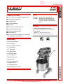
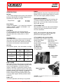
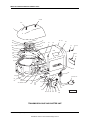
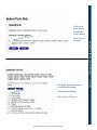
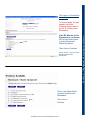
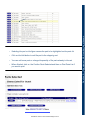
A200 MIXER
TECHNICAL MANUAL
(ML-104858)
(115/60/3)
SPECIFICATION SHEET
INSTALLATION INSTRUCTIONS
OPERATION INSTRUCTIONS
CLEANING INSTRUCTIONS
MAINTENANCE INSTRUCTIONS
TROUBLE SHOOTING INSTRUCTIONS
WIRING DIAGRAMS
CATALOG OF REPLACEMENT PARTS
SMARTPARTS™ USER GUIDE
RECOMMENDED SPARE PARTS LIST
Need other Hobart Services?
•
Warranty Registration
•
Delivery and Installation
•
Preventive Maintenance
•
Hobart Service Contracts
•
Extended Warranty Contracts
•
Parts and Accessories
•
Specialty Programs
•
Water Treatment Programs
•
Air Filtration System
A200 Mixer 115/60/1 Technical ManualPage 2 of 43
Item # ________________________________
Quantity _______________________________
C.S.I. Section 11400
A-200
MIXER
FOOD EQUIPMENT
STANDARD FEATURES
MODEL
■ 1⁄2 H.P. Hobart Designed Fixed Speed Motor
❑ A-200 – 20-Quart All Purpose Mixer
❑ A-200C – 20-Quart All Purpose Mixer with
Maximum Security Correctional
Package (115/60/1, Bench Model
only)
■ Gear-Driven Transmission
■ 15 Minute Timer
■ Three Fixed Speeds
■ Open Base
■ Large, Easy-To-Reach Controls
■ #12 Taper Attachment Hub
■ Stainless Steel Bowl Guard
OPTIONS
❑ Deluxe Nickel Chrome Plate Finish
(115/60/1 and 230/60/1, Bench Model only)
❑ Floor Model
(Base is 21"W x 211⁄2"D x 411⁄4"H)
■ Manual Bowl Lift
■ 20-Quart Stainless Steel Bowl, “B” Flat Beater,
“D” Wire Whip, Cord and Plug
Specifications, Details and Dimensions on Inside and Back.
ACCESSORIES
R
❑ Stainless Steel Bowl
❑ “B” Flat Beater
❑ Stainless Steel “B” Beater
❑ “C” Wing Whip
❑ “D” Wire Whip
❑ “E” Dough Hook
❑ “ED” Dough Hook
❑ “P” Pastry Knife
❑ Bowl Splash Cover
❑ Bowl Scraper
❑ 12 Quart Accessories
❑ Ingredient Chute
❑ 9" Vegetable Slicer
A-200 MIXER
❑ Meat Chopper Attachment
701 S Ridge Avenue, Troy, OH 45374 • 937-332-3000 • 1-800-333-7447
A200 Mixer 115/60/1 Technical ManualPage 3 of 43
A-200
MIXER
FOOD EQUIPMENT
SOLUTIONS/BENEFITS
A-200 MIXER CAPACITY CHART
1
Recommended Maximum Capacities - dough capacities based on 70°F. water and 12% flour moisture.
⁄2 H.P. Hobart Designed Motor
Durability
■ Heavy-duty to meet the most demanding
operations
AGITATORS
SUITABLE FOR
OPERATION
CAPACITY OF BOWL (QTS. LIQUID)
Egg Whites
D
Mashed Potatoes
B&C
Mayonnaise (Qts. of Oil)
B or C or D
Meringue (Qts. of Water)
D
Waffle or Hot Cake Batter
B
Whipped Cream
D or C
Cake, Angel Food
(8-10 oz. cake)
C or I
Cake, Box or Slab
B or C
Cake, Cup
B or C
Cake, Layer
B or C
Cake, Pound
B
Cake, Short (Sponge)
C or I
Cake, Sponge
C or I
Cookies, Sugar
B
Dough, Bread or Roll
(Lt.-Med.) 60% AR
§
ED
Dough, Heavy Bread 55% AR §
ED
Dough Pie
B&P
Dough, Thin Pizza 40% AR
(max. mix time 5 min.)
§‡
ED
Dough, Med. Pizza 50% AR §‡
ED
Dough, Thick Pizza 60% AR §‡
ED
Dough, Raised Donut 65% AR
ED
Dough, Whole Wheat 70% AR
ED
Eggs & Sugar for Sponge Cake
B & C or I
Icing, Fondant
B
Icing, Marshmallow
C or I
Shortening & Sugar, Creamed
B
Pasta, Basic Egg Noodle
(max. mix time 5 min.)
ED
PRODUCT
15-Minute Electric Timer
Convenience, Ease of Use, Consistency
■ Supports recipe mixing times
■ Simplifies operation
■ Provides accurate results and eliminates
overmixing
Three Fixed Speeds
Flexibility, Reliability, Consistency
■ For incorporating, blending, mixing ingredients
■ Supports consistent results and thorough
mixing
Bowl Guard
Protection
■ Safety interlock prevents operation when front
portion of guard is out of position
Gear-Driven Transmission
Durability, Reliability
■ Ensures consistent performance and minimum
downtime with positive drive under heavy loads
Hobart Attachments
Durability, Flexibility
■ Hobart manufactured accessories are designed
for long-term usage under heavy-duty
conditions
■ Large array of attachments provide multiple
uses for recipe and product processing
A-200
20
1 qt.
15 lbs.
10 qts.
11⁄2 pts.
8 qts.
4 qts.
15
20 lbs.
20 lbs.
20 lbs.
21 lbs.
15 lbs.
12 lbs.
15 lbs.
25 lbs.■
15 lbs.■
18 lbs.
9 lbs.■
10 lbs.■
20 lbs.■
9 lbs.*
20 lbs.
8 lbs.
12 lbs.
2 lbs.
16 lbs.
5 lbs.
NOTE: % AR (% Absorption Ratio) - Water weight divided by
flour weight. Capacity depends on moisture content of dough. Above
capacities based on 12% flour moisture at 70°F water temperature.
■
1st Speed
* 2nd Speed
§ If high gluten flour is used, reduce above dough batch size
by 10%.
‡ 2nd Speed should never be used on 50% AR or lower products.
USE OF ICE REQUIRES A 10% REDUCTION IN BATCH SIZE.
1 gallon of water weighs 8.33 lbs.
NOTE: Attachment hub should not be used while mixing.
A200 Mixer 115/60/1 Technical ManualPage 4 of 43
A-200
MIXER
FOOD EQUIPMENT
SPECIFICATIONS
MOTOR:
1
⁄2 H.P., Hobart designed, permanently lubricated ball
bearings, splash-proof, fan cooled. Single-phase is
capacitor-start, induction-run type.
Single Phase
115V
230V
8.2 Amps
4.2 Amps
ELECTRICAL:
115/60/1 and 230/60/1 – U L Listed. Also available in
100/50/1, 220/50/1, 100/60/1 and 220/60/1 – not
submitted for U L Listing.
CONTROLS:
Two-pole toggle switch with No Volt Release.
A 15-minute electric timer is standard. Non-timed
operation obtained by setting timer on “HOLD”
position.
TRANSMISSION:
Gear-driven. Gears are constant mesh heat-treated
alloy steel. Anti-friction ball bearings. A hardened
steel worm and special worm wheel transmit power
from motor to transmission. Grease lubricated.
SPEEDS:
Three positive speeds - Low, Intermediate, and High.
Agitator
(RPM)
Attachment
(RPM)
Low
107
61
Intermediate
198
113
High
361
205
BOWL GUARD:
Heavy-duty stainless steel wire front and solid stainless steel rear portion. Front portion of guard rotates
easily to add ingredients and install or remove
agitator. It detaches in seconds for cleaning in dishwasher or sink. Rear portion of guard can be quickly
cleaned in position. Guard must be in closed position
before mixer will operate. The bowl support lock
prevents the bowl from being lowered while mixer
is running. Bowl support interlock provides further
protection.
BOWL LIFT:
Hand crank operated, self-locking in any position.
FINISH:
Standard Metallic Gray finish, Polyurethane Enamel.
Deluxe finish has nickel-chrome plating on transmission case, bowl support, pedestal and base.
STANDARD EQUIPMENT:
Consists of the mixer unit with cord and plug, one
(1) 20-quart stainless steel bowl, one (1) “B” flat
beater, one (1) “D” wire whip, stainless steel bowl
guard, cord and plug.
ATTACHMENT HUB:
When specified, comes with front-mounted Hobart
standard #12 taper attachment hub for use with
#12 size attachments.
NOTE: Use of attachment hub during mixing
operation may result in a negative impact on
performance and longevity of mixer.
ATTACHMENTS AND ACCESSORIES:
The following are available at extra cost:
Stainless Steel Bowl
“B” Flat Beater
Stainless Steel “B” Beater
“C” Wing Whip
“D” Wire Whip
“E” Dough Hook
“ED” Dough Hook
“P” Pastry Knife
Bowl Splash Cover
Bowl Scraper
12 Quart Accessories
Ingredient Chute
9" Vegetable Slicer
Meat Chopper
Attachment
Hobart Bowl
Scraper
Hobart Ingredient
Chute
LISTED BY: Underwriters Laboratories, Inc. and the National
Sanitation Foundation.
A200 Mixer 115/60/1 Technical ManualPage 5 of 43
A-200
MIXER
FOOD EQUIPMENT
SPECIFICATIONS
ELECTRICAL SPECIFICATIONS: 115/60/1 and
230/60/1 – U L Listed. Also available in 100/50/1,
220/50/1, 100/60/1 and 220/60/1 – not submitted for
U L Listing.
DETAILS AND DIMENSIONS
WEIGHT: 204 lbs. net; 226 lbs. domestic shipping.
Floor Model: 230 lbs. net; 296 lbs. domestic weight.
WARRANTY: Unit has full one-year warranty on
parts, labor and mileage against manufacturer’s
defects. Service contracts are available.
A200/A200-T Mixers
WARNING
ELECTRICAL AND GROUNDING CONNECTIONS MUST COMPLY WITH
THE APPLICABLE PORTIONS OF THE NATIONAL ELECTRICAL CODE
AND/OR OTHER CODES IN FORCE.
A200FT Mixer
WARNING
ELECTRICAL AND GROUNDING CONNECTIONS MUST COMPLY WITH
THE APPLICABLE PORTIONS OF THE NATIONAL ELECTRICAL CODE AND/
OR OTHER CODES IN FORCE.
As continued product improvement is a policy of Hobart, specifications are subject to change without notice.
701 S Ridge Avenue, Troy, OH 45374 • 937-332-3000 • 1-800-333-7447
F-7598 (REV. 6/01)
A200 Mixer 115/60/1 Technical ManualPage 6 of 43
LITHO IN U.S.A. (H-01)
Printed On Recycled Paper
I
N
S
T
R
U
C
T
I
O
N
S
A200 MIXER
MODEL
A200
ML-104859 (without Timer)
ML-104858 (with Timer)
ML-104863 (Deluxe Finish with Timer)
ML-104861 (Floor Model with Timer)
701 S. RIDGE AVENUE
TROY, OHIO 45374-0001
937 332-3000
www.hobartcorp.com
A200 Mixer 115/60/1 Technical ManualPage 7 of 43
FORM 34387 (Feb. 2000)
MODEL A200 MIXER
–2–
A200 Mixer 115/60/1 Technical ManualPage 8 of 43
Installation, Operation, and Care of
A200 MIXER
SAVE THESE INSTRUCTIONS
GENERAL
The model A200 mixer is a 20 quart, bench-type mixer with a 1/2 H.P. motor, and a #12 attachment hub.
With the use of special agitators, a 12 quart bowl may be used on the A200 mixers.
The floor model and the deluxe finish model are equipped with a timer.
Most A200 mixers are equipped with a 0 - 15 minute timer.
There are a variety of attachments and accessories available for all models, and these are explained
in a separate Use and Applications Handbook which is supplied with each mixer.
INSTALLATION
UNPACKING
Immediately after unpacking the mixer, check for possible shipping damage. If this machine is found
to be damaged after unpacking, save the packaging material and contact the carrier within 15 days of
delivery.
Prior to installation, test the electrical service to assure that it agrees with the specifications on the
machine data plate.
LOCATION
Place the mixer on a suitable sturdy level surface. There should be adequate space around the mixer
for the user to operate the controls and install and remove bowls.
Holes are provided in the base to permanently secure the mixer, although this is not necessary in
normal installations. Four plastic plugs are supplied with the mixer to plug these holes if they are not
used.
ELECTRICAL CONNECTIONS (Cord Connected Mixers)
WARNING: THE ELECTRICAL CORD ON THIS MACHINE IS EQUIPPED WITH A THREE-PRONGED
GROUNDING PLUG WHICH MUST BE CONNECTED TO A PROPERLY GROUNDED RECEPTACLE.
IF THE RECEPTACLE IS NOT THE PROPER GROUNDING TYPE, CONTACT AN ELECTRICIAN.
DO NOT REMOVE THE GROUNDING PRONG FROM THE PLUG.
–3–
A200 Mixer 115/60/1 Technical ManualPage 9 of 43
OPERATION
WARNING: MOVING BEATER IN BOWL. KEEP HANDS, CLOTHING, AND UTENSILS OUT WHILE
IN OPERATION, DO NOT USE WITHOUT INTERLOCKED GUARD.
CONTROLS
All models are furnished with an On-Off toggle switch which controls power to the mixer.
The Bowl Guard must be in position or the mixer will not operate. Refer to page 6.
If the Bowl Support is not all the way up, the mixer will not operate unless the On-Off switch is held in
the up position.
The TIMER (if equipped) is used in conjunction with the On-Off switch for timed mixing operations and
will stop the mixer when the desired time has elapsed.
With the timer set on HOLD, the mixer will run until the On-Off switch is turned to Off.
The GEAR SHIFT LEVER (Fig. 1) is used to change speeds. Always stop the mixer before changing
speeds. To change speeds, turn the switch Off, move the gear shift lever to the desired speed, and
turn the switch back On.
Speed 1 (Low) — This speed is for heavy mixtures such as bread dough, heavy batters, and
potatoes.
Speed 2 (Medium) —This speed is for light dough which must rise quickly, cake batters, and some
whipping operations.
Speed 3 (High) — This is a fast speed for light work such as whipping cream, beating eggs, and
mixing thin batters.
The BOWL LIFT HANDLE (Fig. 1) is used to raise and lower the bowl. To raise the bowl, rotate the
handle upward; rotating the handle downward lowers the bowl.
MIXING
This section explains operation of the mixer and how to install bowls, agitators, and attachments. A
separate Use and Applications Handbook is provided with the mixer which contains information on
mixing procedures and outlines specific uses for agitators, attachments, and accessories.
Bowl
New mixer bowls and agitators (beaters, whips, and dough arms) should be thoroughly washed with
hot water and a mild soap solution, rinsed with either a mild soda or vinegar solution, and thoroughly
rinsed with clear water BEFORE being put into service. This cleaning procedure should also be
followed for bowls and agitators before whipping egg whites or whole eggs.
The bowl must be installed before the agitator. To install the bowl, fully lower the bowl support (Fig. 1).
Position the bowl so the alignment bracket on the back of the bowl is in the bowl retainer and the
alignment pins (Fig. 1) on the front of the bowl support fit in the holes on the sides of the bowl. Lock
the bowl in place by rotating the bowl clamps (Fig. 1) over the ears of the bowl.
Agitator
To install an agitator (Fig. 1), the bowl must be installed and fully lowered. Place the agitator in the bowl,
push it up on the agitator shaft, and turn it clockwise to seat the shaft pin in the slot of the agitator shank.
–4–
A200 Mixer 115/60/1 Technical ManualPage 10 of 43
A200
A200 WITH TIMER
4
ON
3
ON
5
6
7
8
2
9
1
10
OFF
11
LD
OFF
12
13
HO
15 14
ATTACHMENT HUB
THUMB SCREW
CONTROL
PANEL
BOWL LIFT
HANDLE
SPLASH
GUARD
GEAR SHIFT
LEVER
APRON
WIRE CAGE
BOWL
SUPPORT
AGITATOR
BOWL
CLAMP
BOWL LIFT
SLIDEWAYS
ALIGNMENT
PIN
PL-53477
Fig. 1
To Raise the Bowl While Mixing
To raise the bowl while the agitator is mixing the product (when required by recipe or when using the
Bowl Scraper Attachment): Load ingredients. Close Wire Cage Assembly. Select Low speed. To
begin mixing, hold the On-Off switch in the up position; then raise the bowl.
Attachments
To install an attachment, loosen the thumb screw on the attachment hub (Fig. 1) and remove the plug.
Insert the attachment into the attachment hub making certain that the square shank of the attachment
is in the square driver of the mixer. Secure the attachment by tightening the thumb screw.
Move the gear shift lever to the desired speed and start the mixer to operate the attachment.
The meat and food chopper attachment should be operated in second or third speed. If material in the
cylinder stalls the mixer, stop the mixer at once. DO NOT attempt to restart the mixer in a lower speed
— remove the adjusting ring, knife, plate, and worm and clear the obstruction. THIS ATTACHMENT
MUST NOT BE USED TO CHOP BREAD CRUMBS.
NOTE: Attachment hub should not be used while mixing.
Bowl Scraper Attachment
The Mixer Bowl Scraper Attachment (when ordered) is provided with a separate instruction manual
covering its installation, operation, use and care.
–5–
A200 Mixer 115/60/1 Technical ManualPage 11 of 43
Bowl Guard (Fig. 2)
The Wire Cage Assembly on the Bowl Guard can be rotated out-of-the-way to add ingredients or
access the bowl and agitator.
To rotate the Wire Cage Assembly to the rear . . .
Rotate the Wire Cage Assembly to the left until it is positioned underneath the Splash Guard. Note
how the grooves on the nylon Retainers allow the Wire Cage to ride around the circular Ridge of the
planetary Drip Cup.
The Wire Cage must be returned to the front and center position for the mixer to operate.
To remove the Wire Cage Assembly for cleaning . . .
Lower the Bowl. Rotate the Wire Cage Assembly to the left until it is positioned underneath the Splash
Guard. Remove both Agitator and Bowl.
While holding the Wire Cage Assembly with both hands, rotate it completely to the left. When the frontcenter Retainer reaches the end of its travel, it can be lowered through the flat on the Ridge of the Drip
Cup. After lowering the front-center Retainer, move the Wire Cage Assembly slightly to the rear so
the Rear Retainers clear the Ridge on the Drip Cup. The Wire Cage Assembly can now be lowered
and removed.
Wash the Wire Cage in a sink or dishwasher; rinse with clear water; and dry with a clean cloth.
The stainless steel Splash Guard can be wiped off or washed easily with a cloth or sponge and warm
soapy water. Rinse with clear water. Dry with a clean cloth.
To reinstall the Wire Cage Assembly . . .
Hold the Wire Cage so its top ring is positioned around the planetary Drip Cup with the grooves in both
nylon Rear Retainers straddling the Ridge on the Drip Cup at the rear. Lift the Wire Cage Assembly
so the front-center Retainer passes up through the flat on the Ridge of the Drip Cup and rotate the Wire
Cage Assembly to the right. The Wire Cage is properly assembled when all three Retainers straddle
the Ridge on the Drip Cup in the three opposed locations. Rotate the Wire Cage Assembly to the right
until it stops at the front-center position.
Rotate the Wire Cage out-of-the-way to install or remove the Agitator and Bowl or to add ingredients.
Return the Wire Cage to its front-center position to operate the mixer.
Front-Center
Retainer
To Remove:
Rotate Wire Cage to the Left 340 Degrees until
the Front-Center Retainer can be lowered
Flat
through the Flat on the Ridge of the Drip Cup.
Ridge Drip Cup
PL-40562-1
Fig. 2
–6–
A200 Mixer 115/60/1 Technical ManualPage 12 of 43
CLEANING
WARNING: UNPLUG MACHINE POWER CORD BEFORE BEGINNING ANY CLEANING
PROCEDURE.
The mixer should be thoroughly cleaned daily.
Bowls and agitators should be removed from the mixer and cleaned in a sink.
DO NOT use a hose to clean the mixer — it should be washed with a clean damp cloth. The apron
(Fig. 1) may be removed by loosening the thumb screws.
The Drip Cup-Splash Guard (which is secured by three screws) should be removed periodically and
wiped clean.
For cleaning the Bowl Guard (including both Wire Cage Assembly and Splash Guard), refer to page 6.
MAINTENANCE
WARNING: UNPLUG MACHINE POWER CORD BEFORE BEGINNING ANY MAINTENANCE
PROCEDURE.
LUBRICATION
Bowl Clamps (Fig. 1) should be lubricated twice a year.
Motor
The motor has sealed ball bearings which require no lubrication maintenance.
Bowl Lift Slideways
The slideways (Fig. 1) should be lubricated once each month. Remove the apron (Fig. 1) secured by
two thumb screws to expose the slideways. Then apply a light coat of Lubriplate 630AA (supplied) to
three sides of both slideways. Replace the apron and thumb screws.
–7–
A200 Mixer 115/60/1 Technical ManualPage 13 of 43
SERVICE
If service is needed on this equipment, contact your local Hobart Service Office.
FORM 34387 (Feb. 2000)
–8–
A200 Mixer 115/60/1 Technical ManualPage 14 of 43
PRINTED IN U.S.A.
TROUBLESHOOTING
A200 MIXER
SYMPTOM
POSSIBLE CAUSE
Mixer will not start.
1.
Circuit protector in open position - check fuse or disconnect switch.
2.
Mixer or attachment overloaded.
3.
Bowl not all the way up.
4.
Wire Cage Assembly is not in the front-center position.
NOTE:
If symptom(s) persists after possible causes have been checked, contact your local Hobart Service Office.
A200 Mixer 115/60/1 Technical ManualPage 15 of 43
ELECTRICAL & GROUNDING CONNECTIONS MUST COMPLY
WITH THE NATIONAL ELECTRICAL CODE AND/OR OTHER
APPLICABLE LOCAL CODES
2
1CR
4
ES
2 START 3
SWITCH
1
4
1S
ON/OFF
3
2LS
BOWL
1CR
6
8
NO
C
1LS
1CR INTERLOCK
0
1
GRN
1
2
3
TIMER
MOTOR
J1
GND
BLK
WHT
MOTOR
START
1 2
MAIN
4
T4
T1
SPLICE
K1
TIMER CONTACTS
CLOSED
OPEN
OFF 1-2 & 1-3
--1-2
HOLD
1-3
--TIMED
1-2 & 1-3
MADE FROM F19264
WIRING DIAGRAM
A-200-T MIXER
UNDER 150 VOLTS
A200 Mixer 115/60/1 Technical ManualPage 16 of 43
AI 2657
CATALOG OF
REPLACEMENT
PARTS
MODEL A200
SERIES MIXER
(INCLUDES MOTOR PARTS)
A200
A200 DT
A200 FT
A200 C
ML-104858
ML-104863
ML-104861
ML-134091
A product of HOBART 701 S. RIDGE AVENUE TROY, OHIO 45374-0001
FORM 34656 Rev. B (April 2005)
A200 Mixer 115/60/1 Technical ManualPage 17 of 43
MODEL A200 SERIES MIXER REPLACEMENT PARTS
1 THRU 4
5
6
7
4
5
8
6
11
7
8
3
9
2
ON
9-10
1
11
0
13
OFF
15
14
PL-55803
SWITCH AND TIMER UNIT
ILLUS.
PL-55803
1
2
3
4
5
6
7
8
9
10
11
PART NO.
00-294650-004-1
00-294650-004-2
00-294650-004-3
00-294650-004-4
00-291746
00-875567
00-873115-00001
SC-013-07
00-123109
SC-128-68
00-291748
F-34656 Rev. B (April 2005)
NAME OF PART
AMT.
Timer Assy. (115 V., 60 Hz.) ...................................................................................................... 1
Timer Assy. (200/300 V., 60 Hz.) ............................................................................................... 1
Timer Assy. (115 V., 50 Hz.) ...................................................................................................... 1
Timer Assy. (220 V., 50 Hz.) ...................................................................................................... 1
Insulator – Switch ...................................................................................................................... 1
Switch Assy. .............................................................................................................................. 1
Switch Plate & Pin Assy. ............................................................................................................ 1
Mach. Screw 5-40 x 1/4 Flat Hd. ................................................................................................. 2
Screw 6-32 x 3/8 Serrated Hd. (Painted and Deluxe) ................................................................ 2
Mach. Screw 6-32 x 3/8 Tx. Button Hd. (SST) (ML-134091) ..................................................... 2
Knob – Timer .............................................................................................................................. 1
-2-
A200 Mixer 115/60/1 Technical ManualPage 18 of 43
© HOBART
MODEL A200 SERIES MIXER REPLACEMENT PARTS
1-2
PL-55796
3
CORRECTIONAL COVER
(ML-134091 ONLY)
ILLUS.
PL-55796
1
2
3
PART NO.
00-875153
SC-128-66
00-438151
NAME OF PART
AMT.
Cover .......................................................................................................................................... 1
Mach. Screw 8-32 x 1/2 Tx. Button Hd. (SST) ........................................................................... 3
Hasp – Plate ............................................................................................................................... 1
-3-
A200 Mixer 115/60/1 Technical ManualPage 19 of 43
F-34656 Rev. B (April 2005)
MODEL A200 SERIES MIXER REPLACEMENT PARTS
3
1-2
9
10
11
12
13-14
15
8
16
7
4
6
5
PL-55793
BOWL GUARD UNIT
ILLUS.
PL-55793
1
2
3
4
5
6
7
8
9
10
11
12
13
14
15
16
PART NO.
SC-066-13
SC-128-73
00-438533
00-438523
SC-122-44
00-438530
00-438527-00001
00-438526
SC-122-82
00-438527-00003
SC-122-44
00-438539
00-438525
SC-122-83
00-438527-00002
SC-122-44
F-34656 Rev. B (April 2005)
NAME OF PART
AMT.
Mach. Screw 8-32 x 1/4 Phil. Truss Hd. (Painted and Deluxe) .................................................. 3
Mach. Screw 8-32 x 1/4 Tx. Button Hd. (SST) (ML-134091) ..................................................... 3
Guard & Drip Cup Assy. ............................................................................................................. 1
Wire Cage Weldment .................................................................................................................. 1
Mach. Screw Special 8-32 x 3/8 Truss Hd. ................................................................................ 2
Stop – Cage ................................................................................................................................ 1
Shoe – Front ............................................................................................................................... 1
Key – Shoe ................................................................................................................................. 1
Mach. Screw 4-40 x 7/16 Oval Hd., Special ................................................................................ 1
Shoe – Adjustable ...................................................................................................................... 1
Mach. Screw – Special 8-32 x 3/8 Truss Hd. ............................................................................. 2
Bumper – Cage ........................................................................................................................... 1
Retainer – Magnet ...................................................................................................................... 1
Mach. Screw 6-32 x 3/8 Truss Hd., Special ............................................................................... 2
Shoe – Fixed .............................................................................................................................. 1
Mach. Screw – Special 8-32 x 3/8 Truss Hd. ............................................................................. 2
-4-
A200 Mixer 115/60/1 Technical ManualPage 20 of 43
MODEL A200 SERIES MIXER REPLACEMENT PARTS
2 THRU 5
20
19
1
21
22
23
24
9 THRU 18
25
34
26-27
8
33
7
6
32
28
29
PL-55801
31
30
PLANETARY AND ATTACHMENT HUB UNIT
ILLUS.
PL-55801
1
2
3
4
5
6
7
8
9
10
11
12
13
14
15
16
17
18
19
20
21
22
23
24
25
26
27
28
29
30
31
32
33
34
PART NO.
00-114824-00001
00-435047-00004
00-435047-00007
00-435047-00004
OR-001-03
SC-119-07
WL-019-79
00-108197-00001
00-012746-00019
00-012746-00005
00-012746-00006
00-012746-00007
00-012746-00008
00-012746-00009
00-012746-00010
00-012746-00012
00-012746-00013
00-012746-00016
00-435065-00002
RR-004-18
00-012430-00055
00-015217
BB-018-17
00-007094
BA-002-09
00-023166-00013
00-023166-00006
BB-005-34
00-023482
00-113936
00-065062-00001
SC-040-09
WL-003-35
00-438524-00002
00-102778-00001
NAME OF PART
AMT.
Plug – Attachment Hub ............................................................................................................... 1
Hub – Attachment (Painted) ....................................................................................................... 1
Hub – Attachment (Deluxe) ........................................................................................................ 1
Hub – Attachment (ML-134091) ................................................................................................. 1
Quad Ring ................................................................................................................................... 1
Mach. Screw 12-24 x 3/4 Flat Hd. (Painted) ............................................................................... 4
Lockwasher ............................................................................................................................... 4
Thumb Screw ............................................................................................................................. 1
Washer – Thrust (0.115 In. Thk.) ............................................................................................. AR
Washer – Thrust (0.080 In. Thk.) ............................................................................................. AR
Washer – Thrust (0.106 In. Thk.) ............................................................................................. AR
Washer – Thrust (0.092 In. Thk.) ............................................................................................. AR
Washer – Thrust (0.086 In. Thk.) ............................................................................................. AR
Washer – Thrust (0.098 In. Thk.) ............................................................................................. AR
Washer – Thrust (0.112 In. Thk.) ............................................................................................. AR
Washer – Thrust (0.119 In. Thk.) ............................................................................................. AR
Washer – Thrust (0.121 In. Thk.) ............................................................................................. AR
Washer – Thrust (0.129 In. Thk.) ............................................................................................. AR
Bevel Drive Gear & Seal Assy. .................................................................................................. 1
Retaining Ring ............................................................................................................................. 1
Key 3/16 x 3/16 x 1 .......................................................................................................................... 1
Pinion – Beater (19T) ................................................................................................................. 1
Ball Bearing ................................................................................................................................ 1
Spring .......................................................................................................................................... 2
Ball 1/4 Dia. ................................................................................................................................... 2
Planetary (Painted) ..................................................................................................................... 1
Planetary (Deluxe) ..................................................................................................................... 1
Ball Bearing ................................................................................................................................ 1
Seal – Oil (1 In. I.D.) .................................................................................................................... 1
Agitator Shaft Assy. (Incls. Item 31) .......................................................................................... 1
Pin ............................................................................................................................................... 1
Cap Screw 1/4-20 x 11/4 Fil. Hd. .................................................................................................. 6
Lockwasher 1/4 Helical ............................................................................................................... 6
Internal Gear (63T) (Incls. Items 24 & 25) ................................................................................. 1
Planetary Assy. (Painted) (Incls. Items 20 thru 23, 26, 28, 29, & 30) ....................................... 1
-5-
A200 Mixer 115/60/1 Technical ManualPage 21 of 43
F-34656 Rev. B (April 2005)
MODEL A200 SERIES MIXER REPLACEMENT PARTS
2
1
3
4
5
6-7
8
9-10
11
PL-55802
BASE UNIT
F-34656 Rev. B (April 2005)
-6-
A200 Mixer 115/60/1 Technical ManualPage 22 of 43
MODEL A200 SERIES MIXER REPLACEMENT PARTS
BASE UNIT
ILLUS.
PL-55802
1
2
3
4
5
6
7
8
9
10
11
PART NO.
00-873229-00003
00-873229-00002
00-108159
WS-018-19
SC-097-53
WS-018-19
SC-062-27
00-074998-00004
WS-018-19
SC-118-10
00-875590-00003
NAME OF PART
AMT.
Base (Painted) (Bench) ............................................................................................................. 1
Base (Deluxe) ............................................................................................................................ 1
Screen – Air ............................................................................................................................... 1
Washer (Bench) (Painted and Deluxe) ..................................................................................... 4
Cap Screw 3/8-16 x 21/4 Hex Hd. (Bench) (Painted and Deluxe) ............................................... 4
Washer (Floor) ........................................................................................................................... 4
Cap Screw 3/8-16 x 13/4 Hex Hd. (Floor) .................................................................................... 4
Block – Riser (Painted) (Floor) ................................................................................................... 1
Washer (Floor) ........................................................................................................................... 4
Cap Screw 3/8-16 x 1 Hex Hd. (Floor) ....................................................................................... 4
Base (Painted) (Floor) ................................................................................................................ 1
-7-
A200 Mixer 115/60/1 Technical ManualPage 23 of 43
F-34656 Rev. B (April 2005)
MODEL A200 SERIES MIXER REPLACEMENT PARTS
56-57
1
2
3
7-8-9
5
4
6
10-11-12
13
14-15
16-17
19
20
18
21
23
22
24
32
54
55
33
34
35
36
25
26
48-49
53
27
47
52
50
51
28
46
29
42
37 THRU 41
30
31
43
44
45
PL-55800
PEDESTAL AND BOWL UNIT
F-34656 Rev. B (April 2005)
-8-
A200 Mixer 115/60/1 Technical ManualPage 24 of 43
MODEL A200 SERIES MIXER REPLACEMENT PARTS
PEDESTAL AND BOWL UNIT
ILLUS.
PL-55800
1
2
3
4
5
6
7
8
9
10
11
12
13
14
15
16
17
18
19
20
21
22
23
24
25
26
27
28
29
30
31
*32
33
34
35
36
37
38
39
40
41
42
43
44
45
46
47
48
49
50
51
52
53
54
55
56
57
PART NO.
SC-060-40
00-087711-00248
00-439892
00-275683
00-295644
00-270776
WL-006-22
SC-041-13
SC-120-38
WL-006-22
SC-011-95
SC-123-34
00-873232-00001
00-438543-00002
00-438543-00004
00-070641-00011
SC-128-73
00-078506
PC-003-55
PS-004-15
00-114430-00002
WS-009-11
WS-009-13
00-438528
00-015215
WS-006-46
PC-003-55
00-012745
00-012782
WS-006-26
NS-036-15
00-479510
SC-022-20
SC-014-55
00-111213-00006
00-111213-00005
00-113016-00001
00-113016-00004
00-113016-00005
00-113016-00006
00-113016-00007
00-121625
SC-060-56
SC-128-81
00-078505
00-478582
00-084854-00001
00-084853-00003
00-084853-00005
00-291444-00001
00-291444-00002
00-291263
00-274614
00-087711-252-1
00-875859
00-438079
00-438078
NAME OF PART
AMT.
Mach. Screw 4-40 x 5/8 Rd. Hd. ................................................................................................. 2
Switch – Bowl Height ................................................................................................................ 1
Insulator – Switch ...................................................................................................................... 1
Bowl Assy. (20 Qt.) (SST) ......................................................................................................... 1
Bowl Assy. (12 Qt.) (SST) ......................................................................................................... 1
Dowel ......................................................................................................................................... 2
Lockwasher 5/16 Light ................................................................................................................. 2
Cap Screw 5/16-18 x 1 Hex Hd. (SST) (Painted) ........................................................................ 2
Cap Screw 5/16-18 x 1 Hex Hd. (Deluxe) ................................................................................... 2
Lockwasher 5/16 Light ................................................................................................................. 2
Mach. Screw 5/16-18 x 1 Fil. Hd. (Painted) ................................................................................. 2
Mach. Screw 5/16-18 x 1 Slotted Fil. Hd. (Deluxe) ...................................................................... 2
Shim (Deluxe) ........................................................................................................................... AR
Pedestal (Painted) ...................................................................................................................... 1
Pedestal (Deluxe) ....................................................................................................................... 1
Thumb Screw 8-32 Special (Painted and Deluxe) .................................................................... 2
Mach. Screw 8-32 x 1/4 Tx. Button Hd. (SST) (ML-134091) ..................................................... 2
Shield – Upper Splash ................................................................................................................ 1
Cotter Pin 1/8 x 3/4 ......................................................................................................................... 1
Spiral Pin 1/4 Dia. x 11/8 Lg. ........................................................................................................... 1
Arm – Bowl Lift .......................................................................................................................... 1
Washer (STL) ........................................................................................................................... AR
Washer (Fiber) ......................................................................................................................... AR
Lift Handle Assy. ........................................................................................................................ 1
Rod – Bowl Lift ........................................................................................................................... 1
Washer ....................................................................................................................................... 2
Cotter Pin 1/8 x 3/4 ......................................................................................................................... 1
Washer – Special ....................................................................................................................... 1
Spring .......................................................................................................................................... 1
Washer ....................................................................................................................................... 1
Stop Nut 3/8-24 Hex Special ........................................................................................................ 1
Bushing – Bowl Lift .................................................................................................................... 2
Mach. Screw 10-24 x 5/8 Flat Hd. (Painted) ............................................................................... 6
Mach. Screw 10-24 x 5/8 Slotted Flat Hd. (Deluxe) ................................................................... 6
Gib – Bowl Support (Painted) .................................................................................................... 2
Gib – Bowl Support (Deluxe) ..................................................................................................... 2
Shim – Bowl Support (0.003 In. Thk.) ...................................................................................... AR
Shim – Bowl Support (0.009 In. Thk.) ...................................................................................... AR
Shim – Bowl Support (0.015 In. Thk.) ...................................................................................... AR
Shim – Bowl Support (0.005 In. Thk.) ...................................................................................... AR
Shim – Bowl Support (0.0075 In. Thk.) .................................................................................... AR
Set Screw – Special .................................................................................................................. 1
Mach. Screw 10-32 x 5/16 Rd. Hd. (Painted and Deluxe) ........................................................... 2
Mach. Screw 10-32 x 1/2 Tx. Button Hd. (SST) (ML-134091) .................................................. 2
Shield – Lower Splash ............................................................................................................... 1
Pin – Bowl Locating ................................................................................................................... 2
Bushing – Bowl Retainer ........................................................................................................... 1
Bowl Support Assy. (Incls. Item 42) (Painted) .......................................................................... 1
Bowl Support Assy. (Incls. Item 42) (Deluxe) ........................................................................... 1
Clamp – Bowl (LH) ..................................................................................................................... 1
Clamp – Bowl (RH Shown) ........................................................................................................ 1
Washer – Belleville ..................................................................................................................... 6
Screw – Pivot ............................................................................................................................. 2
Switch – Reed ............................................................................................................................ 1
Washer – Friction ....................................................................................................................... 1
Splash Cover & Bowl Extension (20 Qt.) .................................................................................. 1
Splash Cover & Bowl Extension (12 Qt.) .................................................................................. 1
* Used On Starting Serial Number #31-1253-999 On ML-104858 and
Serial Number 31-1310-934 On All Other Series A200 Mixers.
-9-
A200 Mixer 115/60/1 Technical ManualPage 25 of 43
F-34656 Rev. B (April 2005)
MODEL A200 SERIES MIXER REPLACEMENT PARTS
4-5-6
2-3
1
7
8
63
14-15
62
9-10
61
11
12
13
16
17
18-19
60
59
58
57
20-21
56
55
22
54
23
24
36
53
51
52
37
25-26-27
50
46 THRU 49
45
42
43
44
41
40
28
39
38 35 34 33
31
32
29
30
TRANSMISSION CASE AND SHIFTER UNIT
F-34656 Rev. B (April 2005)
- 10 -
A200 Mixer 115/60/1 Technical ManualPage 26 of 43
PL-55799
MODEL A200 SERIES MIXER REPLACEMENT PARTS
TRANSMISSION CASE AND SHIFTER UNIT
ILLUS.
PL-55799
1
2
3
4
5
6
7
8
9
10
11
12
13
14
15
16
17
18
19
20
21
22
23
24
25
26
27
28
29
30
31
32
33
34
35
36
37
38
39
40
41
42
43
44
45
46
47
48
49
50
51
52
53
54
55
56
57
58
59
60
61
62
63
PART NO.
00-018231-00003
SC-016-17
SC-015-57
SC-128-82
NS-009-36
00-875751
SC-018-01
00-012708
00-020394-00001
00-875752
00-020395
00-011800-00062
00-012735
00-873802-00005
00-873802-00006
00-438131-00057
WL-003-28
SC-127-85
00-479486
SC-009-49
SC-128-68
00-115231-00002
00-118363
FE-022-84
00-117542-00081
00-117542-00082
00-117542-00080
00-077401
00-875241
00-479471
SC-015-34
SC-128-75
00-290115-00001
00-023946
PS-003-08
BA-002-09
00-111170
NS-013-22
WL-004-06
00-013160
00-873504
00-012733
00-012734
00-012732
00-875567
00-123109
SC-027-28
WL-011-01
NS-010-11
00-873115-00002
00-873140-00001
00-873140-00002
00-123674
00-011800-00116
WL-003-28
SC-119-07
00-067750
NS-009-36
SC-008-56
00-064871
WL-003-28
SC-008-48
WL-003-22
00-875249
00-479470
NAME OF PART
AMT.
Cover – Transmission Case (Painted) ....................................................................................... 1
Mach. Screw 12-24 x 11/4 Oval Hd. (Painted and Deluxe) ........................................................ 2
Mach. Screw 12-24 x 11/2 Oval Hd. (Painted and Deluxe) (ML-134091) .................................. 1
Mach. Screw 1/4-20 x 3/4 Tx. Flat Hd. (SST) (ML-134091) ......................................................... 1
Mach. Nut 12-24 Hex ................................................................................................................. 1
Adapter (ML-134091) ................................................................................................................ 1
Mach. Screw 10-24 x 3/8 Pan Hd. .............................................................................................. 4
Retainer – Twin Bearing ............................................................................................................. 1
Cap – Bearing Retainer .............................................................................................................. 1
Cap – Bearing Retainer (ML-134091) ........................................................................................ 1
Retainer – Bearing ..................................................................................................................... 1
Dowel ......................................................................................................................................... 2
Rod – Shifter Guide .................................................................................................................... 1
Cover – Back (Painted) .............................................................................................................. 1
Cover – Back (Deluxe) ............................................................................................................... 1
Plate – Warning .......................................................................................................................... 1
Lockwasher #12 Light ............................................................................................................... 4
Mach. Screw 12-24 x 21/2 Pan Hd. (Painted and Deluxe) ........................................................ 4
End Cap Screw (ML-134091) .................................................................................................... 4
Mach. Screw 6-32 x 3/8 Rd. Hd. (Painted and Deluxe) .............................................................. 2
Mach. Screw 6-32 x 3/8 Tx. Button Hd. (SST) (ML-134091) ..................................................... 2
Cover – Conduit .......................................................................................................................... 1
Logo – Hobart ............................................................................................................................. 2
Strain Relief 1/2 NPT ..................................................................................................................... 1
Cord & Plug Assy. (3 Cnd., Under 150 V.) ................................................................................. 1
Cord & Plug Assy. (3 Cnd., 200-250 V.) .................................................................................... 1
Cord Assy. (I.E.C.) ...................................................................................................................... 1
Knob – Shifter Handle ................................................................................................................ 1
Handle – Shifter (Incls. Item 28) ................................................................................................. 1
Handle – Shifter (ML-134091) ................................................................................................... 1
Mach. Screw 10-24 x 1/2 (Painted and Deluxe) ......................................................................... 4
Mach. Screw 10-24 x 5/8 Tx. Flat Hd. (SST) (ML-134091) ........................................................ 4
Plate – Shifter Index ................................................................................................................... 1
Gasket – Shifter Index Plate ...................................................................................................... 1
Spiral Pin 1/8 Dia. x 3/4 Lg. ............................................................................................................. 1
Ball 1/4 Dia. ................................................................................................................................... 2
Spring – Detent ........................................................................................................................... 2
Nut 3/8-16 Hex ............................................................................................................................. 1
Lockwasher 3/8 Medium .............................................................................................................. 1
Yoke – Shifter ............................................................................................................................. 1
Cam – Gear Shifter .................................................................................................................... 1
Plunger – Shifter Yoke ............................................................................................................... 2
Spring – Shifter Yoke ................................................................................................................. 2
Retainer – Shifter Yoke Spring ................................................................................................... 2
Switch Assy. (NVR) ................................................................................................................... 1
Screw 6-32 x 3/8 Serrated Hd. ................................................................................................... 2
Mach. Screw 8-32 x 1/4 Rd. Hd. (Ground Screw) ..................................................................... 1
Lockwasher #8 Internal Shakeproof (Ground Screw) (1 Ph.) ................................................. 2
Mach. Nut 8-32 Hex (Ground Screw) (1 Ph.) ........................................................................... 1
Switch Plate & Pin Assy. ............................................................................................................ 1
Case – Transmission (Incls. Items 12 & 53) (Painted) .............................................................. 1
Case – Transmission (Incls. Items 12 & 53) (Deluxe) ............................................................... 1
Label – Warning ......................................................................................................................... 1
Dowel ......................................................................................................................................... 1
Lockwasher #12 Light ............................................................................................................... 4
Mach. Screw 12-24 x 3/4 Hex Hd. .............................................................................................. 4
Transmission Shaft Support & Screw Assy. (Incls. Items 57 & 58) ......................................... 1
Mach. Nut 12-24 Hex ................................................................................................................. 1
Mach. Screw 12-24 x 1/2 Rd. Hd. ............................................................................................... 1
Plug – Friction ............................................................................................................................. 2
Lockwasher #12 Light ............................................................................................................... 3
Mach. Screw 12-24 x 1/2 Rd. Hd. ............................................................................................... 3
Lockwasher #10 Light ............................................................................................................... 4
Shifter Assy. (Incls. Items 29, 33, 35, 36, 37, & 41) .................................................................. 1
Shifter Assy. (ML-134091) (Incls. Items 30, 33, 35, 36, 37, & 41)
- 11 -
A200 Mixer 115/60/1 Technical ManualPage 27 of 43
F-34656 Rev. B (April 2005)
MODEL A200 SERIES MIXER REPLACEMENT PARTS
2
3-4
1
5
6
7
8
9
10
11
12
17
14
13
15
16
18-19-20
PL-55560
21-22
MOTOR PARTS
F-34656 Rev. B (April 2005)
- 12 -
A200 Mixer 115/60/1 Technical ManualPage 28 of 43
MODEL A200 SERIES MIXER REPLACEMENT PARTS
MOTOR PARTS
ILLUS.
PL-55560
1
2
3
4
5
6
7
8
9
10
11
12
13
14
15
16
17
18
19
20
21
22
PART NO.
NS-032-23
00-012430-00004
00-291221
00-070407
00-012754
00-012757
00-873057
SD-015-38
00-271612-00002
00-873203-00002
SD-015-38
00-873125
SD-015-39
WL-008-07
00-087714-042-1
00-087714-042-3
SD-015-38
00-873061-00001
00-873061-00002
00-873061-00003
00-113703
00-070487-00025
NAME OF PART
AMT.
Lock Nut ..................................................................................................................................... 1
Key 1/8 x 1/8 x 1/4 ........................................................................................................................... 1
Gear – Worm (60 Cycle) ............................................................................................................ 1
Gear – Worm (50 Cycle) ............................................................................................................ 1
Washer ....................................................................................................................................... 1
Spring – Shock Absorber ........................................................................................................... 1
Deflector – Grease .................................................................................................................... 1
Self-Tapping Screw 6-32 x 3/8 Phil. Pan Hd., Type TT ............................................................... 2
Switch – Electronic Start (50/60 Hz.) ........................................................................................ 1
Block – Terminal .......................................................................................................................... 1
Self-Tapping Screw 6-32 x 3/8 Phil. Pan Hd., Type TT ............................................................... 1
Bracket – Component Mounting ................................................................................................. 1
Self-Tapping Screw 8-32 x 1/4 Phil. Pan Hd., Type TT ............................................................... 2
Lockwasher #8 Internal Shakeproof ......................................................................................... 2
Relay (2 Pole) (115 V.) ............................................................................................................... 1
Relay (2 Pole) (240 V.) ............................................................................................................... 1
Self-Tapping Screw 6-32 x 3/8 Phil. Pan Hd., Type TT ............................................................... 2
Motor Assy. (115 V., 60 Hz., 1 Ph.) ............................................................................................ 1
Motor Assy. (220 V., 60 Hz., 1 Ph.) ........................................................................................... 1
Motor Assy. (115 V., 50 Hz., 1 Ph.) ............................................................................................ 1
Cable Tie ..................................................................................................................................... 2
Capacitor – Motor Start .............................................................................................................. 1
- 13 -
A200 Mixer 115/60/1 Technical ManualPage 29 of 43
F-34656 Rev. B (April 2005)
MODEL A200 SERIES MIXER REPLACEMENT PARTS
1
2
3
6
5
4
7
32
45
8
9
33
46
10
34
11
47
35
48
12
36
13
37
49
14
38
15
16
17
18
50
51
39
52-53
40
19
41
54
42
20
21
43
55
44
56
22
23
24
25-26
27
28
29
30
PL-55483
31
TRANSMISSION GEAR UNIT
F-34656 Rev. B (April 2005)
- 14 -
A200 Mixer 115/60/1 Technical ManualPage 30 of 43
MODEL A200 SERIES MIXER REPLACEMENT PARTS
TRANSMISSION GEAR UNIT
ILLUS.
PL-55483
1
2
3
4
5
6
7
8
9
10
11
12
13
14
15
16
17
18
19
20
21
22
23
24
25
26
27
28
29
30
31
32
33
34
35
36
37
38
39
40
41
42
43
44
45
46
47
48
49
50
51
52
53
54
55
56
PART NO.
NS-032-29
WS-008-13
BB-020-18
WS-010-18
WS-010-19
WS-010-20
00-107145
00-124730
00-109070-00002
00-124729
00-124732
00-124752
00-124733-00002
00-124744
00-012695
00-012430-00059
00-070035-00001
00-012695
00-124743
00-012723
BB-020-06
00-012430-00017
00-067500-00075
00-124734
00-437342
00-067500-00078
00-114695
00-124946
WS-030-83
00-010928-00002
00-024715-00003
00-012710
WS-006-36
BB-005-02
00-012744
00-291236
00-124736
00-435297
00-012697
00-435297
00-124760
RR-004-19
BB-005-01
SL-002-08
00-012710
WS-006-36
BB-005-02
00-124745
00-124765-00001
00-124748
00-012430-00004
00-124751-00003
00-124749-00002
00-291128
BB-005-01
SL-002-08
00-292799-00002
00-292800
00-292798-00001
00-292798-00002
NAME OF PART
AMT.
Stop Nut 1/2-20 Flexloc ................................................................................................................ 1
Washer – Retaining .................................................................................................................... 1
Ball Bearing ................................................................................................................................ 1
Washer – Bearing Shim (0.002 In. Thk.) .................................................................................. AR
Washer – Bearing Shim (0.003 In. Thk.) .................................................................................. AR
Washer – Bearing Shim (0.010 In. Thk.) .................................................................................. AR
Spacer – Planetary Shaft ........................................................................................................... 1
Sleeve – Roller Clutch Drive ...................................................................................................... 1
Key ............................................................................................................................................. 1
Clutch – Roller ........................................................................................................................... 10
Spring – Roller ........................................................................................................................... 10
Gear – Slow Speed (46T) .......................................................................................................... 1
Gear – Bevel (46T) .................................................................................................................... 1
Gear – Clutch (29T) ................................................................................................................... 1
Bearing – Clutch Gear ................................................................................................................ 1
Key – Clutch Sleeve ................................................................................................................... 2
Sleeve – Clutch .......................................................................................................................... 1
Bearing – Clutch Gear ................................................................................................................ 1
Gear – Lower Clutch (38T) ....................................................................................................... 1
Spacer – Lower ......................................................................................................................... 1
Ball Bearing ................................................................................................................................ 1
Key ............................................................................................................................................. 1
O-Ring ......................................................................................................................................... 1
Shaft – Planetary ....................................................................................................................... 1
Spacer – Bearing (O-Ring) ........................................................................................................ 1
O-Ring ......................................................................................................................................... 1
Seal – Oil .................................................................................................................................... 1
Washer – Fiber ........................................................................................................................... 1
Washer – Retaining (STL) ......................................................................................................... 1
Nut – Special ............................................................................................................................... 1
Acorn Nut 1/2-20 .......................................................................................................................... 1
Nut – Retaining ........................................................................................................................... 2
Washer – Retaining .................................................................................................................... 1
Ball Bearing ................................................................................................................................ 1
Spacer – Upper .......................................................................................................................... 1
Shaft – Transmission (15T) ....................................................................................................... 1
Gear (32T) .................................................................................................................................. 1
Key ............................................................................................................................................. 1
Spacer – Lower ......................................................................................................................... 1
Key ............................................................................................................................................. 1
Gear (23T) .................................................................................................................................. 1
Retaining Ring ............................................................................................................................. 1
Ball Bearing ................................................................................................................................ 1
Spring – Loading ........................................................................................................................ 1
Nut – Retaining ........................................................................................................................... 2
Washer – Retaining .................................................................................................................... 1
Ball Bearing ................................................................................................................................ 1
Washer ....................................................................................................................................... 1
Spacer – Gear ............................................................................................................................ 1
Gear (15T) .................................................................................................................................. 1
Key ............................................................................................................................................. 1
Worm Wheel & Bushing Assy. (60 Hz.) ..................................................................................... 1
Worm Wheel & Bushing Assy. (50 Hz.) ..................................................................................... 1
Shaft – Worm Wheel .................................................................................................................. 1
Ball Bearing ................................................................................................................................ 1
Spring – Loading ........................................................................................................................ 1
Center Shaft Assy. (Incls. Items 7, 8, 9, 12 thru 20, & 24) ....................................................... 1
Transmission Shaft Assy. (Incls. Items 35 thru 42) .................................................................. 1
Worm Wheel Shaft Assy. (60 Hz.) (Incls. Items 48 thru 52 & 54) ............................................ 1
Worm Wheel Shaft Assy. (50 Hz.) (Incls. Items 48 thru 51, 53, & 54) ..................................... 1
- 15 -
A200 Mixer 115/60/1 Technical ManualPage 31 of 43
F-34656 Rev. B (April 2005)
MODEL A200 SERIES MIXER REPLACEMENT PARTS
1-2
4
3
5-6
7
PL-55897
AGITATORS
ILLUS.
PL-55897
1
2
3
4
5
6
7
PART NO.
00-275459
00-275559
00-295165
00-275897
00-477521
00-295119
00-295036
FORM 34656 Rev. B
NAME OF PART
AMT.
“B” Flat Beater (Packaged) ........................................................................................................ 1
“B” Flat Beater (SST) (Packaged) .............................................................................................. 1
“C” Wing Whip (Packaged) ........................................................................................................ 1
“D” Wire Whip (SST) (Packaged) ............................................................................................... 1
“ED” Dough Arm (Packaged) ...................................................................................................... 1
“E” Dough Arm (Packaged) ........................................................................................................ 1
“P” Pastry Knife (Packaged) ...................................................................................................... 1
APRIL 2005
A200 Mixer 115/60/1 Technical ManualPage 32 of 43
PRINTED IN U.S.A.
Online Parts Catalog
User Guide
Note: It is helpful, but not essential to know
the ML (Material List) Number of the
equipment for which a part is needed
Section 1 – If Equipment ML Number is known
Section 2 – If Equipment ML Number is not known
A200 Mixer 115/60/1 Technical ManualPage 33 of 43
User Guide
From
hobartservice.com
select
PARTS
Next
select
SMARTPARTS
Web Browser Pop-up blocker must be turned off for this site in order for SmartParts to operate
A200 Mixer 115/60/1 Technical ManualPage 34 of 43
If the ML Number of
the Equipment is
known,
select
Use SmartParts Now
(We’ll explain what to
do if the ML number of
the Equipment is not
known in Section 2)
Enter the ML number
and click on
Search SmartParts
104352
For this example, the part needed is a Water
Pressure Gauge used on the LX 30 Undercounter
Dishwasher
104352
The ML number of this dishwasher is 104352
A200 Mixer 115/60/1 Technical ManualPage 35 of 43
Section 1 – If Equipment ML Number is known
This is SmartParts
home page
•
Then click on
Continue
The Water Pressure Gauge is
on the Base Assembly
Select Base Assembly
Then click on Continue
A200 Mixer 115/60/1 Technical ManualPage 36 of 43
Section 1 – If Equipment ML Number is known
Click on the
Radio button
to select the
Parts Catalog
Select an appropriate figure size
Locate the part needed (Water
Pressure Gauge) on the drawing
19: Gauge – Water Pressure (LX30/40, LXG, & LXiG Series)
Placing the cursor on the number
will display the Description of the
Part
Click on the number pointing to
the part
A200 Mixer 115/60/1 Technical ManualPage 37 of 43
Section 1 – If Equipment ML Number is known
•
Selecting the part on the figure causes the part to be highlighted on the parts list
•
Click on the Add button to add the part to the shopping cart
•
You can add more parts or change the quantity of the parts already in the cart
•
When finished, click on the Confirm Parts Selected and then on Print Parts List if
you want to print
Use SMARTPARTS Now
A200 Mixer 115/60/1 Technical ManualPage 38 of 43
Section 1 – If Equipment ML Number is known
•
This (again) is SmartParts
home page
If the ML Number of the
Equipment is not known,
click on the Radio button
to select Warewash /
Waste Equipment
Then click on Continue
(Go to Section 1 if you do know
the ML number of the
Equipment)
Click on the Radio button
to select UnderCounter
Dishwasher
Then click on
Continue
A200 Mixer 115/60/1 Technical ManualPage 39 of 43
Section 2 – If Equipment ML Number is not known
For this example, the part
needed is a Water
Pressure Gauge used on
the LX 30 Undercounter
Dishwasher
Then click on
Continue
The Water Pressure Gauge
is on the Base Assembly
Select Base Assembly
Then click on Continue
A200 Mixer 115/60/1 Technical ManualPage 40 of 43
Section 2 – If Equipment ML Number is not known
Click on the Radio button
to select LX Series
Dishwashers
Locate the part needed (Water
Pressure Gauge) on the
drawing
19: Gauge – Water Pressure (LX30/40, LXG, & LXiG Series)
Placing the cursor on the
number will display the
Description of the Part
Click on the number pointing to
the part
A200 Mixer 115/60/1 Technical ManualPage 41 of 43
Section 2 – If Equipment ML Number is not known
Select an appropriate figure size
Selecting the part on the figure causes the part to be highlighted on the parts list
•
Click on the Add button to add the part to the shopping cart
•
You can add more parts or change the quantity of the parts already in the cart
•
When finished, click on the Confirm Parts Selected and then on Print Parts List if
you want to print
Use SMARTPARTS Now
A200 Mixer 115/60/1 Technical ManualPage 42 of 43
Section 2 – If Equipment ML Number is not known
•
A200 MIXER
SEPTEMBER 2009
PRODUCT SERVICE DEPARTMENT
TROY, OH. 45374-0001
RECOMMENDED SPARE PARTS LIST
A200 MIXER
ML-104568
Qty.
Part Number
Description
1
291221
Worm
1
124751-3
Worm Wheel and Bushing Assembly
1
124734
Planetary Shaft
1
120388
Switch, Timed
1
70487-18
Capacitor
1
271612-2
Electronic Start Switch
1
87714-42-1
Relay 120V
1
87711-248
Bowl Height Switch
1
438527-1
Front Shoe
1
438527-3
Adjustable Shoe
1
438539
Cage Bumper
1
438525
Magnet Retainer
1
438527-2
Fixed Shoe
1
113936
Beater Shaft
Page 1 of 1
A200 Mixer 115/60/1 Technical ManualPage 43 of 43
A200 Mixer