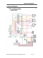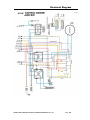
1
Owner’s Manual Keep with machine for reference MODEL CMA-181GW INSTALLATION & OPERATION Rev 1.00 CMA GLASSWASHERS 12700 KNOTT AVENUE GARDEN GROVE, CALIFORNIA 92841 800-854-6417 FAX 714-895-2141 www.cmaglasswashers.com TABLE OF CONTENTS MODEL CMA-181GW 1. 2. 3. SPECIFICATIONS ........................................................................................ 2 1.1. CMA-181GW ........................................................................................................................ 2 1.2. CMA-181GW OPERATIONAL CYCLE ..................................................................................... 3 GETTING STARTED ..................................................................................... 5 2.1. INTRODUCTION TO CMA-181GW .......................................................................................... 5 2.2. RECEIVING AND INSTALLATION.............................................................................................. 6 2.2.1. Electrical ....................................................................................................................... 6 2.2.2. Plumbing........................................................................................................................ 6 2.2.3. BETA Detergent And Rinse Dispenser. ......................................................................... 7 2.2.4. Safe Ttemp Feature ........................................................................................................ 7 2.2.5. Booster Heater Setup ..................................................................................................... 9 2.2.6. Installers Checklist ........................................................................................................ 9 OPERATION ............................................................................................... 10 3.1. 4. INITIAL SETUP ...................................................................................................................... 10 3.1.1. Dema Valve and Dema Flow Disc. .............................................................................. 10 3.1.2. Rinse and Wash Temperatures .................................................................................... 10 3.1.3. Post Instructions .......................................................................................................... 10 3.2. STARTUP PROCEDURES......................................................................................................... 10 3.3. OPERATING AND CLEANING INSTRUCTIONS ......................................................................... 11 3.4. PREVENTIVE MAINTENANCE CHART .................................................................................... 12 3.5. QUICK SERVICE GUIDE .......................................................................................................... 13 3.6. TROUBLESHOOTING .............................................................................................................. 14 PARTS KIT ................................................................................................. 17 4.1. INITIAL PARTS KIT (P/N 1100.66) ........................................................................................ 17 5. CUSTOMER NOTICE ................................................................................. 18 6. ELECTRICAL DIAGRAM ............................................................................ 19 www.cmaglasswashers.com 1. Specifications 1.1. METRIC EQUIVALENT CMA-181GW WATER CONSUMPTION PER RACK .75 GAL. (2.83 L) PER HOUR 17.9 GAL. (67.6 L) WASH TIME-SEC 94 94 RINSE TIME-SEC 16 16 DWELL TIME-SEC 10 10 2 MIN. 2 MIN. 30 30 WASH TANK CAPACITY 2.5 GAL. (9.46 L) PUMP CAPACITY 38 GPM (144 LPM) OPERATING CYCLE TOTAL CYCLE OPERATING CAPACITY RACKS PER HOUR WATER REQUIREMENTS REQUIRED MINIMUM TEMP. * 110°F (43°C) RECOMMENDED TEMP. ** 140°F (60°C) WATER INLET ½” 1.27cm DRAIN CONNECTION 1” 2.54cm 20 PSI±5 PSI 1.41 kg/cm2 WASH-°F 150°F -160°F (65.5°C/71°C) RINSE -°F 180°F -195°F (82°C/90°C) RINSE PRESSURE SET CYCLE TEMPERATURES FRAME DIMENSIONS DEPTH 25” (63.5 cm) WIDTH 24” (60.96 cm) HEIGHT 33 ¼” (84.45 cm) MAX CLEARANCE FOR GLASSWARE ELECTRICAL RATING* BOOSTER HEATER WASH PUMP MOTOR 11-1/4” (28.6 cm) 208 VOLTS 1 PH—60 Hz 230 VOLTS 1 PH—60 Hz 33 AMPS 35 AMPS 5.3 kW 6.5 kW ¾ HP ¾ HP THIS SYSTEM REQUIRES THREE POWER WIRES, WHICH INCLUDES A CURRENT CARRYING NEUTRAL. AN ADDITIONAL FOURTH WIRE MUST BE PROVIDED FOR MACHINE GROUND. SHIPPING WEIGHT 234# (106 kg) * For machines having "SAFETY TEMP" feature. ** For faster heat recovery. MODEL CMA-181GW INSTALLATION & OPERATION MANUAL Rev. 1.00 Page 2 1.2. CMA-181GW Operational Cycle The CMA-181GW Operational Cycle has a total cycle time of 2 minutes (120 seconds). The Timing Diagram and the steps listed below detail the individual functions that are executed during each Operational Cycle. Seconds: 0 10 20 30 40 50 60 70 80 90 100 110 120 Instant Start Relay Cam Timer Motor Cam Rinse Cycle Cam Wash Cycle Cam Optional Drain Pump Cam Safe-TTemp Cam 1. With the machine powered up toggling the START switch begins a cycle. a) Toggling the START switch energizes both the Cam Timer motor and the Instant Start Relay. The Instant Start Relay latches ON the power to the Cam Timer motor so that the START switch can be released a moment after it has been toggled without the Cam Timer motor losing power. b) After about 1.5 seconds the Cam Timer’s first cam—the Cam Timer Motor Cam— latches ON the power to the Cam Timer motor and drops out the Instant Start Relay. The Cam Timer motor continues to run for a total of 2 minutes, at which time it switches OFF—resetting the Cam Timer—and waits for the next START command. 2. The Cam Timer’s third cam controls the Wash Pump. The Wash Pump comes ON about 3 seconds into the Operational Cycle and continues to run for 94 seconds. This 94-second period is the Wash Cycle. 3. At the same time that the Wash Pump comes ON the Cam Timer’s fourth cam powers ON the Optional Drain Pump—if one is present—and keeps it running for about 7 seconds before powering OFF. This cam turns ON again midway through the Rinse Cycle and stays ON for 10 seconds, turning OFF 2 seconds after the Rinse Cycle has completed. 4. About 3 seconds after the Wash Cycle has completed the Cam Timer’s second cam, which controls the Rinse Cycle, turns ON—energizing the Water Solenoid—and stays ON for 16 seconds. This 16-second period is the Rinse Cycle. MODEL CMA-181GW INSTALLATION & OPERATION MANUAL Rev. 1.00 Page 3 5. When the cam timer assembly approaches the final rinse portion of the cycle, the “Safe-TTemp” sixth micro switch will pause cam timer assembly if the booster heater has not reached 180 degrees. Machine will remain in wash cycle mode until 180-degree rinse temperature is reached, and at this time the cam timer will advance automatically into the rinse cycle and dispense 180 degrees rinse water over the dishes. MODEL CMA-181GW INSTALLATION & OPERATION MANUAL Rev. 1.00 Page 4 Getting Started 2. Getting Started 2.1. Introduction to CMA-181GW The CMA-181GW is a hot water sanitizing, single rack, under-counter glasswasher. It is a standalone machine featuring a self-contained booster heater. The only external connections necessary are power supply, water supply, drainpipe, and optional chemical dispensers. The machine uses re-circulated wash water and fresh water final-rinse. Operation of the CMA-181GW is extremely user friendly. To initially fill the machine each day, push the switch marked “FILL”. The machine is full when water begins to flow into the scrap tray. The booster tank heater will maintain the wash water temperature at 155°F. The booster heater will produce a minimum of 180°F final rinse water each cycle. The supply water to the CMA-181GW must be a minimum of 140°F at 24 PSI (Pounds per Square Inch) with a 6 GPM (Gallons Per Minute) flow rate and 60 GPH (Gallons Per Hour) recovery rate. The pipe supplying the water must be ½” minimum. The plumbing connection is located at the back of the machine. (See specification sheet on page 2). The drain is a 1" barbed fitting on the back of the machine for easy attachment of your drain hose. This manual is structured to provide a complete reference guide to the CMA-181GW. It is presented in a manner that all users will be able to comprehend and use as an effective tool in supporting the operation and maintenance of the glasswasher. The first section explains how the machine is packaged and what to look for when receiving the machine. After unpacking the machine, this manual explains how to install and set up the machine for use. Requirements are given for plumbing, wiring, and space considerations. These attributes of the machine are always taken into consideration by our well-trained sales representatives prior to the order being placed. In the manual, guidance is also given for installation to ensure that the machine will be able to run at optimum conditions. The Operation Section of the manual may be used for instruction and procedures when required. We make this portion of the manual easy to understand so that all levels of operators may be able to read and comprehend the operation of the machine. The function of the machine itself is mostly automatic and takes little training to put into full operation. The Operation Section also includes diagnostic considerations for the machine when problems occur. We are committed to providing the best machines and customer service in the food industry and your feedback is welcome. DISCLAIMER OF LIABILITY OF WARRANTY: CMA EXPRESSLY DISCLAIMS ANY AND ALL WARRANTIES, EXPRESS OR IMPLIED, RELATING TO THE INSTALLATION OF ANY AND ALL CMA EQUIPMENT THAT IS INSTALLED BY CHEMICAL DEALERS, CONTRACTED SERVICERS OR THIRD PARTY SERVICERS TO CMA EQUIPMENT. IF THE INSTALLATION INSTRUCTIONS ARE NOT FOLLOWED EXACTLY (TO THE LETTER), OR, IF ANY PERSON OR COMPANY CONDUCTING THE INSTALLATION OF THE CMA EQUIPMENT, REVISE THE INSTALLATION PROCEDURES OR ALTER THE INSTRUCTIONS IN ANY MANNER, THE CMA WARRANTY BECOMES VOID. IF, DUE TO THE IMPROPER INSTALLATION OF CMA EQUIPMENT, THIS EQUIPMENT CEASES TO OPERATE PROPERLY OR AFFECTS OTHER PARTS OF THE CMA DISHWASHING EQUIPMENT, IN THAT THE OTHER PARTS BECOME DEFECTIVE, THE CMA WARRANTY BECOMES VOID. CMA WILL NOT BE LIABLE OR RESPONSIBLE OR WARRANT CMA EQUIPMENT, DUE TO IMPROPER INSTALLATION OF ANY CMA MODEL GLASSWASHER. MODEL CMA-181GW INSTALLATION & OPERATION MANUAL Rev. 1.00 Page 5 2.2. Receiving and Installation The glasswasher is shipped from the factory in a corrugated box on a wooden pallet. The installation guidelines give a systematic procedure for setting up the machine. Start by removing the packaging material. Unwrap the machine and check for the following component parts: The Wash Tank Scrap Screen is shipped inside the wash cavity of the machine. This screen must be in place during operation. It has been designed to perform two basic functions: 1. Strain water that is circulating through the spray arms and pump assembly. 2. A basket to catch broken glass, or heavy solids that may plug the impeller. Set the machine in place, and level from side-to-side and front-to-back. 2.2.1. Electrical 1 A 50-amp, single-phase 230 volt, 60 Hz dedicated circuit should be used to supply electrical energy to the CMA-181GW glasswasher (see specification sheet page 2). This system requires three power wires, which include a current carrying neutral. An additional fourth wire must be provided for ground. CMA and local codes require the CMA-181GW to be hardwired using #8 AWG (90°C) copper wire (minimum). Approximately 4-feet of ¾” flexible conduit with power leads (L-1, L-2, Neutral and Ground) extending out of the conduit are provided for easily connecting the power at installation. The power connection must be located such that there is sufficient length of the flexible conduit remaining to permit the machine to be moved for cleaning. 2.2.2. Plumbing 2 The machine is equipped with a ½” NPT connection located at the lower left-hand corner (facing the back) of the machine. A 140°F water line should be plumbed to this point (see specification sheet page 2). The water line used must be of sufficient length and flexibility to permit the machine to be moved for cleaning. Important: This machine is equipped with Dema Valve and Dema Flow Disc which requires an unrestricted water supply line minimum of ½”. The supply water to the CMA-181GW must be a minimum of 140°F at 24 PSI (Pounds per Square Inch) with a 6 GPM (Gallons Per Minute) flow rate and 60 GPH (Gallons Per Hour) recovery rate. The pipe supplying the water must be ½” minimum. The plumbing connection is located at the back of the machine. (See specification sheet on page 2). The CMA-181GW may be supplied with an optional drain pump for elevated drains. For floor gravity drain applications the drain pump should not be used and a good commercial grade hose needs to be connected to the discharge side of the diverter valve (drain valve) and run to the floor drain. If a drain pump is used with a floor drain, the drain hose must rise 12 to 16” before dropping to the floor drain (to reduce any chance of the pump cavitations). Warning: If the water hardness is greater than 6 grains per gallon, a water softener is required to prevent damage to heating elements (scale build- up) and booster tank rinse flow restriction. Rinse flow restriction will cause the booster tank to expand and contract causing metal flex, which will eventually crack the tank. 1,2 All electrical and plumbing connections must be made by a qualified person who will comply with all available Federal, State, and Local Health, Electrical, Plumbing and Safety codes MODEL CMA-181GW INSTALLATION & OPERATION MANUAL Rev. 1.00 Page 6 2.2.3. BETA Detergent And Rinse Dispenser. Optional built-in Beta dispenser (CMA p/n 14585.00) has easy access for chemical settings behind the front kick panel. Both initial charge and recharge are factory pre-set. Basic settings for both detergent and rinse speed are 50%. Operating fine-adjustment screws on the dispenser can control the amount of chemicals drawn into chemical lines. Undercounter machine with the optional dispenser must be ordered separately, as option at time of order. Optional dispenser has to be pre-wired prior to shipment (see electrical diagram for wiring options). 2.2.4. Safe Ttemp Feature The CMA “SafeTtemp” feature assures the final rinse cycle is always at a consistent minimum of 180 degrees. How it works: the “SafeTtemp” function operates off the 5th cam (labeled “SafeTtemp”) on the timer assembly. When the cam timer assembly completes the wash cycle, and approaches the final rinse portion of the cycle, the “SafeTtemp” micro switch will drop into the cam slot and pause cam timer assembly if the booster heater has not reached 180 degrees. Machine will remain in wash cycle mode until 180 degree rinse temperature is met, and at this time the cam timer will advance automatically into the rinse cycle and dispense 180 degrees rinse water over the dishes. Note: if Safe Ttemp cam is not to be used, it becomes a spare cam. CMA -180“SafeTtemp” Installation Instructions: 1) Remove the 4cam timer assembly (note wire colors and wire placement for all 4cam timer micro switches) and install 5cam timer in its place. 2) Place all wires removed from 4cam timer assembly in exact position on 5cam timer assembly. MODEL CMA-181GW INSTALLATION & OPERATION MANUAL Rev. 1.00 Page 7 3) The cam timer motor receives (1) yellow wire and (1) white wire (re-connect the yellow wire only from glasswasher harness to the motor). 4) The “SafeTtemp” 5 cam timer assembly kit includes a two white harness – connect white wire with female bullet connector to the timer motor, stripped end to #22/NC on contactor, and spade end to center terminal 5th micro switch. 5) Connect white wire with male bullet connector from the kit to the white wire with female bullet connector coming from glasswasher harness, stripped end to #21/NC on contactor, and spade end to top terminal on 5th micro switch. L1 L2 L3 HEATER CONTACTOR T1 T2 T3 21 A1 N/C 22 A2 SafeTtemp harness Dishmachine harness Female bullet connector Male bullet connector Female bullet connector Male bullet connector MODEL CMA-181GW INSTALLATION & OPERATION MANUAL Rev. 1.00 Page 8 2.2.5. Booster Heater Setup The booster tank must be filled with water before the heating element is energized. For this reason the “High Limit Switch” has intentionally been disconnected at the factory and will require re-connection before the heating element will turn on. Follow the procedure below to complete the initial installation: 1. Close the door on the machine. 2. Turn the Power switch to the "ON" position. 3. Hold the “FILL” switch in until water overflows into the scrap tray. 4. Turn the Power switch to the "OFF" position. 5. Connect blue wire with disconnect, identified by red tag, to the High Limit Switch which is located behind the thermostat behind the front kick panel. 2.2.6. Installers Checklist Glasswasher checked for concealed damage Hot water supply is 140° F (60 C) — minimum Incoming water supply line is ½” — minimum Incoming water supply is 6 GPM minimum at 24 PSI Supply circuit breaker for machine is properly sized (50 amp) Service voltage and phase type are correct to machine data plate If drain pump is used, drain hose rises 12 to 16” before dropping to drain Drain hose is installed with air gap (discharge 1” above drain) Glasswasher is properly grounded Glasswasher is properly leveled Machine circuit breaker is labeled “GLASSWASHER” Machine has been “hard-wired” with correctly sized wire Booster tank has been filled with water (before High Limit Switch is reset) High Limit Switch for heater has been reset (after Booster Tank has been filled) MODEL CMA-181GW INSTALLATION & OPERATION MANUAL Rev. 1.00 Page 9 Operation 3. Operation 3.1. Initial Setup 3.1.1. Dema Valve and Dema Flow Disc. New Dema Valve made of stainless steel is more compatible with various water conditions. Dema Flow Disc has been placed on the exit side of the water valve. The Flow Disc reduces pressure to the standard recommended 20 PSI. 3.1.2. Rinse and Wash Temperatures 1. Turn the Power switch to the "ON" position. 2. After the machine has warmed up for about ten-minutes, note the wash and rinse temperatures. The wash temperature must be 155°F minimum. The rinse temperature must be 180°F minimum 3. If necessary, adjust the temperatures by removing the front kick panel and turning the thermostat adjustment clockwise to increase, counterclockwise to decrease. This one adjustment controls both temperatures. 3.1.3. Post Instructions 1. Install wall chart and instruct machine operator on proper cleaning and operation of the CMA-181GW. 3.2. Startup Procedures 1. Open the door of the machine and check that the scrap screen is in place, and that the spray arms and end plugs are secure. 2. Close the door of the machine and turn the Power switch to the "ON" position. 3. Hold the fill button about 25 seconds or until the water overflows into the scrap tray. 4. Once the water is filled to the proper level, press the rocker switch marked “START” – the machine will automatically begin its cycle. 5. Check machine’s operating temperatures — Adjust if necessary. See section 3.1.2 Rinse and Wash Temperatures. 6. At the end of the wash period, drain the machine by pushing the rocker switch marked “DRAIN”. Clean the wash tank screen and scrap tray screen. Remove and clean the spray arms. (See wall chart instructions). 3 Rinse cycle temperature must be observed during a rinse cycle while the machine is in operation.. MODEL CMA-181GW INSTALLATION & OPERATION MANUAL Rev. 1.00 Page 10 Operation 3.3. Operating and Cleaning Instructions MODEL CMA-181GW INSTALLATION & OPERATION MANUAL Rev. 1.00 Page 11 Operation 3.4. Preventive Maintenance Chart MODEL CMA-181GW INSTALLATION & OPERATION MANUAL Rev. 1.00 Page 12 Operation 3.5. Quick service guide MODEL: CMA 181GW HIGH TEMP UNDER COUNTER TECHNICAL ISSUE Door leaks Thermometer failure Rinse water temperature low /high Pump motor not running Pump motor runs continuously CAUSE SOLUTION Pressure regulator is not set properly Set regulator to 18-20 psi Faulty rinse micro switch Replace micro switch Obstruction in drain hose Check hose & clean Scrap exit screen Clean exit screen Faulty drain pump Replace pump Machine not level Adjust machine legs to level Machine is leaning forward Adjust machine legs to level Wash arm end cap missing Replace end cap Door gasket Loose wire at display, board or transformer Replace gasket Secure connectors Faulty temperature sensing wire Correct, replace Faulty temperature sensing unit Replace unit Faulty transformer Replace transformer Scaled heating element Booster heater’s thermostat not properly set Clean scale from heater Adjust thermostat Incoming water temperature to booster heater below 140 F Adjust external water heater in the facility Loose lead connections Faulty # 3 micro switch Check and crimp connectors Replace micro switch Faulty contactor Replace contactor Faulty wash pump motor Faulty # 3 micro switch Replace wash pump motor Replace micro switch Faulty contactor Replace contactor Water regulator not adjusted properly Adjust regulator to 18-20 PSI Low water pressure at the final rinse Clogged final rinse spray jets Missing final rinse spray end cap Clean jets Replace end cap Low incoming water pressure from facility Increase pressure to 18-20 psi Scrap trap overflows over night Faulty water solenoid diaphragm Clean or replace diaphragm Low wash or rinse water temp. Check temperature settings Poor cleaning results Wash arm bearing or jets Clean bearing and arm jets Rinse arm bearing or jets Tank discharge screen dirty Clean bearing and arm jets Clean screen Drain valve not operating Check power to drain valve Drain valve faulty Replace Drain valve Wash tank will not drain. MODEL CMA-181GW INSTALLATION & OPERATION MANUAL Rev. 1.00 Page 13 Operation 3.6. Troubleshooting PROBLEM LIKELY CAUSE SOLUTION Machine inoperative Power off at circuit breaker Reset circuit breaker Defective power switch Replace power switch Door is open Close door Control panel is pulled out Secure control panel Defective reed switch Replace reed switch Defective timer assembly Replace timer assembly* Defective pump motor contactor Replace contactor Defective motor Replace motor Defective reed switch Replace reed switch Defective pump motor contactor Replace contactor High limit switch opened or defective Reset or replace switch Defective thermostat Replace thermostat Defective heater contactor Replace heater contactor Defective heater Replace heater Defective thermostat Replace thermostat Defective heater contactor Replace heater contactor Motor inoperative Motor runs with door open Heater (no heat) Heater (never turns off) *The timer assembly motor or micro switches can be replaced independently if that’s the only component that’s failed. MODEL CMA-181GW INSTALLATION & OPERATION MANUAL Rev. 1.00 Page 14 Operation PROBLEM LIKELY CAUSE SOLUTION Low heat during operation Low incoming water temperature Turn up supply water heater (below 140° F) Insulate supply water pipe Thermostat out of adjustment Adjust thermostat Cold water mixing with supply Isolate hot water from cold water Defective heater Replace heater Pressure regulator out of adjustment Adjust pressure regulator Defective pressure gauge (actual pressure is okay) Replace pressure gauge Regulator at maximum but rinse pressure still low Insufficient water supply flow Supply larger supply line Defective water solenoid valve Replace water solenoid valve Low rinse water flow Low rinse water pressure See “Low rinse water pressure” in PROBLEM column Limed up rinse arm spray nozzles De-lime rinse arm nozzles Defective water solenoid valve Replace water solenoid valve Defective (Rinse Relay) ice cube relay Replace ice cube relay Rinse water runs with door open Defective reed switch Replace reed switch Water overflows scrap tray onto floor Drain hose is kinked Un-kink drain hose Drain hose is not properly elevated before dropping to drain (if drain pump is used) Elevate drain hose 12 to 16” above pump before dropping to drain Defective timer assembly Replace timer assembly* Defective drain pump (if drain pump is used) Replace drain pump Defective start switch (cycle light will not light either) Replace start switch Defective timer assembly Replace timer assembly* Low rinse water pressure No rinse water flow With power on, activating start switch does not begin cycle *The timer assembly motor or micro switches can be replaced independently if that’s the only component that’s failed. MODEL CMA-181GW INSTALLATION & OPERATION MANUAL Rev. 1.00 Page 15 Operation PROBLEM LIKELY CAUSE SOLUTION Start switch requires > 1 second activation to run cycle Defective (Instant Start) ice cube relay Replace ice cube relay Activating fill switch does not fill machine Defective drain/fill switch Replace drain/fill switch Defective water solenoid valve Replace water solenoid valve Defective water solenoid valve Replace water solenoid valve Defective drain/fill switch Replace drain/fill switch Defective timer assembly Replace timer assembly* Defective (Rinse Relay) ice cube relay Replace ice cube relay Drain hose is kinked Un-kink drain hose Defective drain/fill switch Replace drain/fill switch Defective drain valve Replace drain valve Cycle light does not light while cycle runs Defective cycle light Replace cycle light (green) Power light does not light but machine runs Defective power light Replace power light (red) Wash tank or final rinse temperature does not display Defective digital thermometer Replace digital thermometer Both the wash tank temperature and the final rinse temperature do not display Defective thermometer transformer Replace thermometer transformer Wash tank or final rinse displays wrong temperature Defective digital thermometer Replace digital thermometer Defective thermister Replace thermister Fill (rinse water) won’t shut off Activating drain switch does not drain machine *The timer assembly motor or micro switches can be replaced independently if that’s the only component that’s failed. MODEL CMA-181GW INSTALLATION & OPERATION MANUAL Rev. 1.00 Page 16 4. Parts Kit 4.1. Initial Parts Kit (P/N 1100.66) P/N DESCRIPTION Qty 15504.00 Motor Contactor, 2-Pole 20 Amp 1 15504.50 Heater Contactor, 2-Pole 35 Amp 1 00501.00 2-Minute Timer Motor 1 00631.00 Ice Cube Relay 120 V 1 15523.00 Rocker Switch Start Momentary 1 15523.50 Rocker Switch Drain/Fill 1 15524.00 Rocker Switch Power Maintained 1 00556.10 Reed Switch 1 03623.00 1/2” Vacuum Breaker Repair Kit – Watts 1 00707.00 1/2” Water Solenoid Repair Kit – J/E 1 04113.00 L1X/L1-C Drain Valve 120V 1 00206.30 Pump Seal Kit 1 13417.89 Heater Thermostat 1 17523.60 High Limit Switch 200°F 1 00411.00 Microswitch 1 03202.66 Thermocouple (Control Products) 1 03604.30 Dema Valve Repair Kit 3/8",1/2" & 3/4 41015.60 Water Solenoid Coil Only 110V MODEL CMA-181GW INSTALLATION & OPERATION MANUAL Rev. 1.00 Page 17 Parts Manual 5. Customer Notice CMA-181GW Installation Guidelines Improper installation of this product may void the warranty on this machine. Please follow these guidelines for recommended installation and to ensure the warranty of this model is authorized by CMA Glasswashers. Glasswasher Installation Requirements 1. Machine must be level. Adjust leveling feet to accommodate uneven floor surfaces. 2. Drain height should not exceed maximum height of 16”. Connect supplied drain line to 3-way valve on back of machine and gravity feed to the floor drain. 3. Check the Pressure. Recommended pressure is between 18-20 psi. 4. Water supply to machine must be a minimum 120°F for 3minute cycle models and 140°F for 2 minute cycle models. 5. A four-wire, (neutral, ground and two 110v lines) 220v single phase connection is required. There is a six foot cord provided with the machine. CMA recommends a minimum 50-amp dedicated circuit, but you should consult your local building code requirements for proper breaker size. Activating/Adjusting the Booster Heater 1. Booster heater must be filled with water prior to connecting the blue wire from high limit switch. The high limit switch can be found by removing the front panel and locating the red button on the front of the heater tank. 2. Once the booster has been connected, the thermostat should be adjusted to maintain 180°F during the final rinse cycle. The thermostat is located on the front of the booster tank and is accessible by removing the front panel on the machine. Automatic Dispensing Equipment 1. Applications utilizing automated dispensers for administering warewash chemicals must use 110v dispenser equipment. There is a 110v power block for installing this equipment inside the control panel. MODEL CMA-181GW INSTALLATION & OPERATION MANUAL Rev. 1.00 Page 18 Electrical Diagram 6. Electrical Diagram 181GW MODEL CMA-181GW INSTALLATION & OPERATION MANUAL Rev. 1.00 Page 19 Electrical Diagram 181GW MODEL CMA-181GW INSTALLATION & OPERATION MANUAL Rev. 1.00 Page 20