1
2314.book Page i Wednesday, June 9, 2004 8:30 AM
Falcon®
DOS Portable Data Terminals
User’s Guide
2314.book Page ii Wednesday, June 9, 2004 8:30 AM
PSC Inc
959 Terry Street
Eugene, Oregon 97402
Telephone: (541) 683-5700
Fax: (541) 345-7140
An Unpublished Work - All rights reserved. No part of the contents of this documentation or the procedures described therein
may be reproduced or transmitted in any form or by any means without prior written permission of PSC Inc. or its wholly owned
subsidiaries ("PSC"). Owners of PSC products are hereby granted a non-exclusive, revocable license to reproduce and transmit
this documentation for the purchaser's own internal business purposes. Purchaser shall not remove or alter any proprietary
notices, including copyright notices, contained in this documentation and shall ensure that all notices appear on any reproductions of the documentation.
Should future revisions of this manual be published, you can acquire printed versions by contacting PSC Customer Administration. Electronic versions may either be downloadable from the PSC web site (www.pscnet.com) or provided on appropriate
media. If you visit our web site and would like to make comments or suggestions about this or other PSC publications, please let
us know via the “Contact PSC” page.
Disclaimer
Reasonable measures have been taken to ensure that the information included in this manual is complete and accurate. However, PSC reserves the right to change any specification at any time without prior notice.
PSC is a registered trademark of PSC Inc. The PSC logo is a trademark of PSC. All other trademarks and trade names referred
to herein are property of their respective owners.
Falcon® is a registered trademark of PSC Inc. and of its wholly owned subsidiaries.
PhoenixCARD Manager Plus ©1993, 1994 Phoenix Technologies Ltd.
Microsoft Windows®, Windows® 95, Windows® 98, Windows® 2000, Windows® CE .NET, Windows® NT, and Windows® XP
are registered trademarks of Microsoft Corporation.
Patents
This product may be covered by one or more of the following patents: 4603262 • 4639606 • 4652750 • 4672215 • 4699447 • 4709195 • 4709369
• 4749879 • 4792666 • 4794240 • 4798943 • 4799164 • 4820911 • 4845349 • 4861972 • 4861973 • 4866257 • 4868836 • 4879456 • 4939355 •
4939356 • 4943127 • 4963719 • 4971176 • 4971177 • 4991692 • 5001406 • 5015831 • 5019697 • 5019698 • 5086879 • 5115120 • 5144118 •
5146463 • 5179270 • 5198649 • 5200597 • 5202784 • 5208449 • 5210397 • 5212371 • 5212372 • 5214270 • 5229590 • 5231293 • 5232185 •
5233169 • 5235168 • 5237161 • 5237162 • 5239165 • 5247161 • 5256864 • 5258604 • 5258699 • 5260554 • 5274219 • 5296689 • 5298728 •
5311000 • 5327451 • 5329103 • 5330370 • 5347113 • 5347121 • 5371361 • 5382783 • 5386105 • 5389917 • 5410108 • 5420410 • 5422472 •
5426507 • 5438187 • 5440110 • 5440111 • 5446271 • 5446749 • 5448050 • 5463211 • 5475206 • 5475207 • 5479011 • 5481098 • 5491328 •
5493108 • 5504350 • 5508505 • 5512740 • 5541397 • 5552593 • 5557095 • 5563402 • 5565668 • 5576531 • 5581707 • 5594231 • 5594441 •
5598070 • 5602376 • 5608201 • 5608399 • 5612529 • 5629510 • 5635699 • 5641958 • 5646391 • 5661435 • 5664231 • 5666045 • 5671374 •
5675138 • 5682028 • 5686716 • 5696370 • 5703347 • 5705802 • 5714750 • 5717194 • 5723852 • 5750976 • 5767502 • 5770847 • 5786581 •
5786585 • 5787103 • 5789732 • 5796222 • 5804809 • 5814803 • 5814804 • 5821721 • 5822343 • 5825009 • 5834708 • 5834750 • 5837983 •
5837988 • 5852286 • 5864129 • 5869827 • 5874722 • 5883370 • 5905249 • 5907147 • 5923023 • 5925868 • 5929421 • 5945670 • 5959284 •
5962838 • 5979769 • 6000619 • 6006991 • 6012639 • 6016135 • 6024284 • 6041374 • 6042012 • 6045044 • 6047889 • 6047894 • 6056198 •
6065676 • 6069696 • 6073849 • 6073851 • 6094288 • 6112993 • 6129279 • 6129282 • 6134039 • 6142376 • 6152368 • 6152372 • 6155488 •
6166375 • 6169614 • 6173894 • 6176429 • 6188500 • 6189784 • 6213397 • 6223986 • 6230975 • 6230976 • 6237852 • 6244510 • 6259545 •
6260763 • 6266175 • 6273336 • 6276605 • 6279829 • 6290134 • 6290135 • 6293467 • 6303927 • 6311895 • 6318634 • 6328216 • 6332576 •
6332577 • 6343741 • 6,568,598 • 6,578,765 • AU703547 • D312631 • D313590 • D320011 • D320012 • D323492 • D330707 • D330708 •
D349109 • D350127 • D350735 • D351149 • D351150 • D352936 • D352937 • D352938 • D352939 • D358588 • D361565 • D372234 • D374630
• D374869 • D375493 • D376357 • D377345 • D377346 • D377347 • D377348 • D388075 • D446524 • EP0256296 • EP0260155 • EP0260156 •
EP0295936 • EP0325469 • EP0349770 • EP0368254 • EP0442215 • EP0498366 • EP0531645 • EP0663643 • EP0698251 • GB2252333 •
GB2284086 • GB2301691 • GB2304954 • GB2307093 • GB2308267 • GB2308678 • GB2319103 • GB2333163 • GB2343079 • GB2344486 •
GB2345568 • GB2354340 • ISR107546 • ISR118507 • ISR118508 • JP1962823 • JP1971216 • JP2513442 • JP2732459 • JP2829331 •
JP2953593 • JP2964278 • MEX185552 • MEX187245 • RE37166 • Other Patents Pending
2314.book Page i Wednesday, June 9, 2004 8:30 AM
CONTENTS
PSC Falcon® Datalight® DOS End User License Agreement ..................v
PSC Falcon® DOS Warranty .............................................................. viii
Safety Information .............................................................................ix
Falcon Model 31X and 32X ...................................................................................................................... ix
Falcon Model 33X .....................................................................................................................................x
Falcon Model 34X .................................................................................................................................... xi
Advisory Statement ................................................................................................................................. xii
Regulatory Statements ........................................................................................................................... xii
Radio Frequency Interference ........................................................................................................ xii
Canadian Compliance Statement ................................................................................................... xii
Laser Safety ..................................................................................... xiii
International Caution Statements for CLASS 1, 2, 3R, II, and IIA Laser Devices .................................. xiii
English ........................................................................................................................................... xiii
French ............................................................................................................................................ xiii
German .......................................................................................................................................... xiv
Italian ............................................................................................................................................. xiv
Danish ............................................................................................................................................ xiv
Dutch ............................................................................................................................................... xv
Swedish .......................................................................................................................................... xv
Finnish ............................................................................................................................................ xv
Norwegian ...................................................................................................................................... xvi
Portuguese ..................................................................................................................................... xvi
Spanish ......................................................................................................................................... xvii
User’s Guide
i
2314.book Page ii Wednesday, June 9, 2004 8:30 AM
Index
Chinese ..........................................................................................................................................xvii
Japanese ......................................................................................................................................xviii
Preface ............................................................................................. xix
Overview ................................................................................................................................................. xx
Falcon Model Numbers ........................................................................................................................... xx
Style Conventions ..................................................................................................................................xxii
Document Conventions ..................................................................................................................xxii
Keys and Keystroke Conventions ..................................................................................................xxii
Chapter 1: Falcon Basics .....................................................................1
Turning the Falcon On and Off .................................................................................................................2
First-Time Use ..................................................................................................................................2
“Please Wait” Messages ...................................................................................................................2
Power Supplies .........................................................................................................................................3
Batteries ....................................................................................................................................................3
Electrical Rating ................................................................................................................................3
Auto-Shutoff ......................................................................................................................................3
Low-Battery Warning ........................................................................................................................3
Replacement Batteries ......................................................................................................................4
Battery Disposal ................................................................................................................................4
Replacing the Batteries .....................................................................................................................5
Removing the Pistol Grip ........................................................................................................................10
Replacing the Pistol Grip with the Hand-Strap ................................................................................11
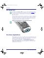
The Serial Port ........................................................................................................................................12
The Falcon Applications .........................................................................................................................12
Chapter 2: Falcon Keypads ................................................................13
Overview .................................................................................................................................................14
Falcon 31x 41-Key Keypad .....................................................................................................................15
Comparing Falcon 31x 41-Key Keypad and PC Keyboard .............................................................15
Input Modes ...................................................................................................................................16
International Characters ..................................................................................................................18
Falcon 32x 57-Key Keypad .....................................................................................................................19
Comparing Falcon 32x 57-Key Keypad with PC Keyboard ............................................................19
Input Modes ...................................................................................................................................21
International Characters ..................................................................................................................21
Repeating Keystrokes .....................................................................................................................22
Falcon 33x/34x 25-Key Keypad ..............................................................................................................22
Comparing Falcon 25-Key Keypads with PC Keyboards ................................................................23
Icons and Input Modes ....................................................................................................................24
Double Action Key Mode ................................................................................................................25
ii
Falcon® DOS Portable Terminals
2314.book Page iii Wednesday, June 9, 2004 8:30 AM
Index
Falcon 33x/34x 38-Key Keypad ..............................................................................................................27
Comparing Falcon 38-Key Keypads with PC Keyboards ................................................................28
Icons and Input Modes ....................................................................................................................29
Double Action Key Mode ................................................................................................................30
Double Strike Mode ........................................................................................................................30
Press and Wait Mode ......................................................................................................................30
International Characters ..................................................................................................................31
Falcon 34x 48-Key Keypad .....................................................................................................................32
Comparing Falcon 48-Key Keypads with PC Keyboards ................................................................33
Icons and Input Modes ....................................................................................................................34
Repeating Keystrokes .....................................................................................................................34
Chapter 3: Falcon Viewport ...............................................................35
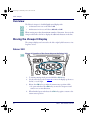
Overview .................................................................................................................................................36
Moving the Viewport Display ...................................................................................................................36
Falcon 31X ......................................................................................................................................36
Falcon 32X ......................................................................................................................................37
Falcon 33X and 34X .......................................................................................................................38
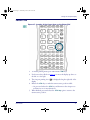
Adjusting the Contrast .............................................................................................................................41
Using the Backlight .................................................................................................................................42
Chapter 4: Falcon Accessories ...........................................................43
Integrated Scanners ................................................................................................................................44
Falcon Dock ............................................................................................................................................44
Falcon 4-Slot Dock ..................................................................................................................................44
Vehicle Mount Powered Dock .................................................................................................................45
Portable Battery Charger ........................................................................................................................45
Chapter 5: Using a Scanner ...............................................................47
Overview .................................................................................................................................................48
Scanning Bar Codes ...............................................................................................................................48
Triggers ...................................................................................................................................................49
The Laser Module ...................................................................................................................................50
Using the Long-Range Laser ..................................................................................................................51
Spot Beam Timeout Mode ..............................................................................................................51
Release Scan Mode ........................................................................................................................52
Linear Imager ..................................................................................................................................52
Attaching a Bar Code Reader .................................................................................................................52
Chapter 6: The Falcon Dock ...............................................................55
Overview .................................................................................................................................................56
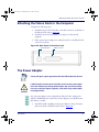
Attaching the Falcon Dock to the Computer ...........................................................................................57
The Power Adapter .................................................................................................................................57
User’s Guide
iii
2314.book Page iv Wednesday, June 9, 2004 8:30 AM
Index
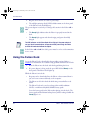
Using the Falcon Dock ............................................................................................................................58
Chapter 7: Falcon Four-Slot Dock ......................................................61
About the Falcon 4-Slot Dock .................................................................................................................62
Front Panel .....................................................................................................................................62
Back Panel ......................................................................................................................................64
Installation ...............................................................................................................................................65
Power Adapter ................................................................................................................................65
Cables .............................................................................................................................................65
Connecting the Dock to the Host ....................................................................................................65
Creating a Dock Network ........................................................................................................................66
Using the 4-Slot Dock .............................................................................................................................67
Charging a Falcon’s Batteries .........................................................................................................67
Transferring Data ............................................................................................................................67
Chapter 8: The Falcon Vehicle Mount Powered Dock .........................69
Overview .................................................................................................................................................70
Power Supply ..........................................................................................................................................70
Fuse Replacement ..........................................................................................................................71
Vehicle 12VDC Connection ............................................................................................................71
Installation ...............................................................................................................................................72
Mounting Bracket ............................................................................................................................73
Bottom Mounting Bracket ................................................................................................................73
Custom Mounting Brackets .............................................................................................................74
Using the Vehicle Mount Powered Dock ................................................................................................75
Chapter 9: Maintenance, Troubleshooting, and Technical Support ....79
Maintaining the PDT ...............................................................................................................................80
Troubleshooting ......................................................................................................................................80
Bar Codes .......................................................................................................................................80
Batteries ..........................................................................................................................................81
Dock ................................................................................................................................................81
RF Connectivity Troubleshooting ...................................................................................................82
Serial Communications ...................................................................................................................83
Technical Support ...................................................................................................................................83
Index ................................................................................................85
iv
Falcon® DOS Portable Terminals
2314.book Page v Wednesday, June 9, 2004 8:30 AM
PSC Falcon® Datalight® DOS End User
License Agreement
Notice to End User: The PSC Product you have acquired contains Software, which is integral to the product’s operation. This
Software is being provided to you under license, subject to the terms and conditions of this Agreement. If you use the PSC Product, you will be deemed to have accepted the terms and conditions of this Agreement. If you do not intend to be bound to the
terms of this Agreement, PSC is not willing to license the Software to you, you may not use the PSC Product or the Software,
and you must contact the party from whom you acquired the PSC Product for instructions.
This End User Software License Agreement (“Agreement”) is a legally binding agreement governing the licensing of the Software and Documentation by PSC Inc. and its wholly owned subsidiaries and affiliates (“PSC”) to the entity or person who has
purchased or otherwise acquired a PSC Product (“End User”). For purposes of this Agreement, any software that is associated
with a separate end-user license agreement is licensed to you under the terms of that license agreement. PSC and End User
hereby agree as follows:
1. Definitions.
1.1 “Documentation” means materials such as user’s guides, program reference guides, quick reference guides, manuals, or
similar materials associated with or related to the PSC Product, whether in printed, “online”, or other form.
1.2 “Proprietary Information” means: (a) source code, object code, software, documentation, and any related internal design,
system design, data base design, algorithms, technology, technical data or information, implementation techniques, and trade
secrets related to the Software, (b) any other trade secrets marked appropriately or identified as proprietary or confidential, and
(c) any information that End User, under the circumstances, should recognize as confidential. Proprietary Information does not
include any information that the receiving party can establish was (1) in the public domain, (2) already in the receiving party’s
possession or rightfully known prior to receipt, (3) rightfully learned from a third party not in violation of any other's proprietary
rights, or (4) independently developed without access to Proprietary Information.
1.3 “PSC Product” means PSC’s Falcon® Datalight® DOS Products, including all preloaded Software in or provided in connection
with the PSC Product and all Documentation related to such product, which has been purchased or otherwise acquired by End
User, whether obtained directly or indirectly from PSC.
1.4 “Software” means any software or computer programs of PSC or its third party licensors in machine readable form which is
either preloaded in or provided in connection with the PSC Product, whether obtained directly or indirectly from PSC, including
any related update or upgrade such as enhancements or modifications.
2. Scope Of License Granted.
2.1 PSC grants to End User a non-exclusive, non-transferable, perpetual license to use the Software, solely on a PSC Product,
in machine-readable form only, solely for End User's internal business purposes. This Agreement does not convey ownership of
the Software to End User. Title to the Software shall be and remain with PSC or the third party from whom PSC has obtained a
licensed right. As used in this Agreement, the term “purchase” or its equivalents when applied to the Software shall mean
“acquire under license.”
2.2 End User shall not copy, modify, decompile, disassemble, reverse engineer, or otherwise reproduce or remanufacture the
Software, whether modified or unmodified, nor sell, assign, sublicense, distribute, lend, rent, give, or otherwise transfer the Software to any other person or organization, for purposes other than as expressly provided in this Agreement, or to the extent specifically allowed under foreign law solely for the purposes of interoperability, without PSC’s prior written consent.
3. Transfers, Support.
3.1 Any copying, installing, reproduction, remanufacture, reverse engineering, electronic transfer, or other use of the Software on
other than a PSC Product will be a material breach of this Agreement.
3.2 End User shall not sell, assign, sublicense, distribute, lend, rent, give, or otherwise transfer a PSC Product containing Software to any third party unless such third party agrees with PSC in writing to be bound by the terms and conditions of this Agreement. Any such transfer of a PSC Product absent such agreement shall be null and void.
3.3 End User may obtain support for Software from PSC at PSC’s standard support fees and under PSC’s standard support
terms and conditions in effect at the time the support is requested.
User’s Guide
v
2314.book Page vi Wednesday, June 9, 2004 8:30 AM
PSC Falcon® Datalight® DOS End User License Agreement
4. Intellectual Property.
End User acknowledges that the Software constitutes valuable trade secrets of PSC or PSC’s third party licensors and that the
Software is protected by intellectual property laws and treaties. The license set forth in this Agreement does not transfer to End
User any ownership of PSC’s or its third party licensors' copyrights, patents, trademarks, service marks, trade secrets, or other
intellectual property rights and End User shall have no right to commence any legal actions to obtain such rights. End User shall
not remove, modify, or take any other action that would obscure any copyright, trademark, patent marking, or other intellectual
property notices contained in or on the PSC Product.
5. Proprietary Information.
5.1 End User acknowledges that Proprietary Information is the confidential, proprietary, and trade secret property of PSC and
PSC’s third party licensors and End User acquires no right or interest in any Proprietary Information.
5.2 End User shall not disclose, provide, or otherwise make available the Proprietary Information of PSC or its third party licensors to any person other than End User’s authorized employees or agents who are under confidentiality agreement, and End
User shall not use the Proprietary Information other than in conjunction with use of the PSC Product exclusively for End User’s
internal business purposes. End User shall take steps to protect the Proprietary Information no less securely than if it were End
User's own intellectual property.
5.3 The provisions of this Proprietary Information Section shall survive and continue for five (5) years after the termination of this
Agreement.
6. Limited Warranty.
6.1 PSC warrants that, under normal use and operation, the PSC Product will conform substantially to the applicable Documentation for the period specified in the Documentation. During this period, for all reproducible nonconformities for which PSC has
been given written notice, PSC will use commercially reasonable efforts to remedy nonconformities verified by PSC. End User
agrees to supply PSC with all reasonably requested information and assistance necessary to help PSC in remedying such nonconformities. For all defects reported to PSC within the warranty period, PSC’s liability is limited to providing End User with one
copy of corrections or responding to End User's problem reports according to PSC's standard assistance practices. PSC does
not warrant that the product will meet End User's requirements or that use of the product will be uninterrupted or error free, or
that PSC's remedial efforts will correct any nonconformance. This limited warranty does not cover any product that has been
subjected to damage or abuse, whether intentionally, accidentally, or by neglect, or to unauthorized repair or unauthorized installation, and shall be void if End User modifies the product, uses the product in any manner other than as established in the Documentation, or if End User breaches any of the provisions of this Agreement.
6.2 EXCEPT AS PROVIDED IN THIS AGREEMENT, THE PSC PRODUCT IS PROVIDED “AS IS” AND PSC MAKES NO WARRANTIES OF ANY KIND, EXPRESS OR IMPLIED, WRITTEN OR ORAL, WITH RESPECT TO THE PRODUCT, AND SPECIFICALLY DISCLAIMS THE IMPLIED WARRANTIES OF MERCHANTABILITY AND FITNESS FOR A PARTICULAR PURPOSE.
7. Infringement.
7.1 PSC will defend End User against any claim in a lawsuit that the PSC Product furnished hereunder infringes a United States
patent or copyright of a third party and PSC will pay any damages finally awarded against End User by a court of competent
jurisdiction that are attributable to such claim or will pay End User’s part of any settlement that is attributable to such claim, provided, that 1) End User notifies PSC promptly in writing of the claim, 2) PSC controls the defense or settlement of the claim, and
3) End User cooperates fully with PSC in such defense or settlement. All notices of a claim should be sent to PSC Inc., 959 Terry
Street, Eugene, OR 97402.
7.2 In the defense or settlement of any such claim, PSC may, at its option, 1) procure for End User the right to continue using the
PSC Product, 2) modify the PSC Product so that it becomes non-infringing, 3) replace the PSC Product with an equivalent product not subject to such claim, or 4) provide End User an opportunity to return the PSC Product and receive a refund of the purchase price paid, less a reasonable allowance for use.
7.3 PSC shall have no liability to End User for claims of infringement based upon 1) the use of any PSC Product in combination
with any product which PSC has not either furnished or authorized for use with such PSC Product 2) the use of any PSC Product
designed, manufactured, or modified to the specifications of End User, or 3) End User’s modification of the PSC Product without
written authorization from PSC.
7.4 THE FOREGOING STATES PSC’S COMPLETE AND ENTIRE OBLIGATION CONCERNING CLAIMS OF PATENT, COPYRIGHT, OR OTHER INTELLECTUAL PROPERTY INFRINGEMENT, CANCELS AND SUPERCEDES ANY PRIOR AGREEMENTS, WHETHER ORAL OR WRITTEN, BETWEEN THE PARTIES CONCERNING SUCH CLAIMS, AND WILL NOT BE
MODIFIED OR AMENDED BY ANY PAST, CONTEMPORANEOUS, OR FUTURE AGREEMENTS OR DEALINGS BETWEEN
vi
Falcon® DOS Portable Terminals
2314.book Page vii Wednesday, June 9, 2004 8:30 AM
THE PARTIES, WHETHER ORAL OR WRITTEN, EXCEPT AS SET FORTH IN A FUTURE WRITING SIGNED BY BOTH PARTIES.
8. Limitation Of Liability.
EXCEPT AS PROVIDED IN SECTION 7, PSC SHALL NOT BE LIABLE FOR ANY CLAIMS AGAINST END USER BY ANY
OTHER PARTY. IN NO EVENT SHALL PSC'S LIABILITY FOR DAMAGES, IF ANY, WHETHER BASED UPON CONTRACT,
TORT (INCLUDING NEGLIGENCE), PRODUCT LIABILITY, STRICT LIABILITY, WARRANTY, OR ANY OTHER BASIS,
EXCEED THE PRICE OR FEE PAID BY END USER FOR THE PSC PRODUCT. UNDER NO CIRCUMSTANCES SHALL PSC
BE LIABLE TO END USER OR ANY THIRD PARTY FOR LOST PROFITS, LOST DATA, INTERRUPTION OF BUSINESS OR
SERVICE, OR FOR ANY OTHER SPECIAL, CONSEQUENTIAL, CONTINGENT, INDIRECT, INCIDENTAL, PUNITIVE, EXEMPLARY, OR OTHER SIMILAR DAMAGES, EVEN IF PSC HAS BEEN ADVISED OF THE POSSIBILITY OF SUCH DAMAGES.
9. Government Restricted Rights; International Use.
9.1 Use, duplication, or disclosure of the Software by the U.S. Government is subject to the restrictions for computer software
developed at private expense as set forth in the U.S. Federal Acquisition Regulations at FAR 52.227-14(g), or 52.227-19 or in the
Rights in Technical Data and Computer Software clause at DFARS 252.227-7013(c)(1)(ii), whichever is applicable.
9.2 If End User is using the PSC Product outside of the United States, End User must comply with the applicable local laws of the
country in which the PSC Product is used, with U.S. export control laws, and with the English language version of this Agreement. The provisions of the “United Nations Convention on International Sale of Goods” shall not apply to this Agreement.
10. Termination.
10.1 Either party may terminate this Agreement or any license granted under this Agreement at any time upon written notice if
the other party breaches any provision of this Agreement.
10.2 Upon termination of this Agreement, End User immediately shall cease using any non-preloaded software and shall return
to PSC or destroy all non-preloaded software covered by this Agreement, and shall furnish PSC with a certificate of compliance
with this provision signed by an officer or authorized representative of End User. For preloaded software, End User agrees to
sign a waiver prepared by PSC concerning further use of the preloaded Software. End User’s resumed or continued use of the
preloaded Software after termination shall constitute End User’s agreement to be bound by the terms and conditions of this
Agreement for such use.
11. General Provisions.
11.1 Entire Agreement; Amendment. This document contains the entire agreement between the parties relating to the licensing
of the Software and supersedes all prior or contemporaneous agreements, written or oral, between the parties concerning the
licensing of the Software. This Agreement may not be changed, amended, or modified except by written document signed by
PSC.
11.2 Notice. All notices required or authorized under this Agreement shall be given in writing, and shall be effective when
received, with evidence of receipt. Notices to PSC shall be sent to the attention of the General Counsel, PSC Inc., 959 Terry
Street, Eugene, OR 97402, or such other address as may be specified by PSC in writing.
11.3 Waiver. A party’s failure to enforce any of the terms and conditions of this Agreement shall not prevent the party’s later
enforcement of such terms and conditions.
11.4 Governing Law; Venue: This Agreement and the rights of the parties hereunder shall be governed by and construed in
accordance with the laws of the State of Oregon U.S.A, without regard to the rules governing conflicts of law. The state or federal
courts of the State of Oregon located in either Multnomah or Lane counties shall have exclusive jurisdiction over all matters
regarding this Agreement, except that PSC shall have the right, at its absolute discretion, to initiate proceedings in the courts of
any other state, country, or territory in which End User resides, or in which any of End User's assets are located.
11.5 Attorneys’ Fees. In the event an action is brought to enforce the terms and conditions of this Agreement, the prevailing party
shall be entitled to reasonable attorneys’ fees, both at trial and on appeal.
- END -
User’s Guide
vii
2314.book Page viii Wednesday, June 9, 2004 8:30 AM
PSC Falcon® DOS Warranty
Warranty
Falcon products are guaranteed against defects in materials and workmanship for the period specified at the time of sale. This
warranty shall apply to Falcon Portable Data Terminals (PDT's), Base Stations for the Falcon and Chargers for the Falcon.
Cables, mounts and other accessory items are specifically warranted for a period of 90 days from product purchase. Customer
must notify PSC of the claimed defect before the expiration of the Warranty period and obtain from PSC a return authorization
number for return of the product to designated PSC service center. If PSC determines Customer’s claim is valid, PSC will repair
or replace product without additional charge for parts and labor. Customer shall be responsible for packaging and shipping the
product to the designated PSC service center, with shipping charges prepaid. PSC shall pay for the return of the product to Customer if the shipment is to a location within the country in which the PSC service center is located. Customer shall be responsible
for paying all shipping charges, duties, taxes, and any other charges for products returned to any other locations.
Warranty is subject to the limitations and exclusions set forth in the paragraphs that follow.
WARRANTY SET FORTH ABOVE IS IN LIEU OF ANY OTHER WARRANTIES, EXPRESS OR IMPLIED, INCLUDING MERCHANTABILITY AND FITNESS.
Exclusions
Warranty coverage shall not apply to any claimed defect, failure or damage which PSC determines was caused by: abuse,
neglect, improper use of product; failure to provide product maintenance, including but not limited to cleaning of the display in
accordance with product reference guide; installation or service of product by other than PSC representatives; use of product
with any other instrument, equipment or apparatus; modification or alteration of product or units with Warranty Void labels that
have been tampered with. External cables and replacement of upper window/cartridge due to scratching, stains or other degradation will not be covered under the Warranty. External power supplies returned for service must be accompanied by the original
product for performance of service.
Returned products that PSC inc. has determined are not covered by Warranty, will be charged PSC Inc. standard repair rates
then in effect for repair of product. Replacement of display due to scratching, stains or other degradation will not be covered
under Warranty. If a product is determined to be not repairable customer will be notified and product may be returned to customer at their request. A minimum repair fee may be charged.
Limitation of Liability
PSC's REPAIR OR REPLACEMENT OF DEFECTIVE PRODUCT AS SET FORTH ABOVE IS THE CUSTOMER’S SOLE AND
EXCLUSIVE REMEDY ON ACCOUNT OF CLAIMS OF BREACH OF WARRANTY OR PRODUCT DEFECT. UNDER NO CIRCUMSTANCES WILL PSC BE LIABLE TO CUSTOMER OR ANY THIRD PARTY FOR ANY LOST PROFITS, OR ANY INCIDENTAL, CONSEQUENTIAL IN-DIRECT, SPECIAL OR CONTINGENT DAMAGES REGARDLESS OF WHETHER PSC HAD
ADVANCE NOTICE OF THE POSSIBILITY OF SUCH DAMAGES.
Assignment
Customer may not assign or otherwise transfer its rights or obligations under Warranty except to a purchaser or transferee of
product. No attempted assignment or transfer in violation of this provision shall be valid or binding upon PSC.
Risk of Loss
Customer shall bear risk of loss or damage for product in transit to PSC. PSC shall assume risk of loss or damage for product in
PSC's possession or product being returned to Customer by PSC, except such loss or damage as may be caused by the negligence of Customer, its agents or employees. In the absence of specific written instructions for the return of product to Customer,
PSC will select the carrier, but PSC shall not thereby assume any liability in connection with the return shipment.
User’s Guide
viii
2314.book Page ix Wednesday, June 9, 2004 8:30 AM
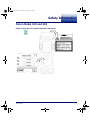
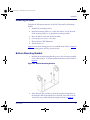
Safety Information
Falcon Model 31X and 32X
Figure 1. Back View of a Falcon Model 31x and Labels
User’s Guide
ix
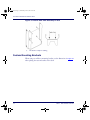
2314.book Page x Wednesday, June 9, 2004 8:30 AM
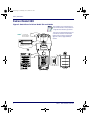
Safety Information
Falcon Model 33X
Figure 2. Back View of a Falcon Model 33x and Labels
These illustrations are for illustrative purposes
only. View the actual labels on the product itself
for applicable model and safety specifications.
AVO ID EXPO SURE
LASER LIGHT IS EMMITED
FRO M THIS APERTURE
AVOID EXPOSURE
LASER LIGHT IS EMMITED
FROM THIS APERTURE
Some units come with Linear Imagers and some
come with Laser Scanners. The Laser Safety
Caution shown to the left will only appear and
apply to those devices equipped with Laser
Scanners.
LASER LIGHT - DO NO T STARE INTO BEAM
CLASS 2 LASER PRO DUCT.
1mw-680nm-100sec. IEC 825-1:1993/
EN60825 - 1: 1994
THIS EQ UIPMENT CO MPLIES W ITH PART 15 O F THE FCC RULES.
O PERATIO N IS SUBJECT TO THE FO LLOW ING TW O CO NDITIO NS:
(1) THIS DEVICE MAY NO T CAUSE HARMFUL INTERFERENCE,
AND (2) THIS DEVICE MUST ACCEPT ANY INTERFERENCE
RECEIVED INCLUDING INTERFERENCE THAT MAY CAUSE
UNDESIRED O PERATIO N.
LASER LIGHT - DO NO T STARE INTO BEAM
CLASS 2 LASER PRO DUCT.
1mw-6 80nm-100sec. IEC 825-1:1993/
EN6 0825 - 1: 1994
THIS EQUIPMENT CO MPLIES W ITH PART 15 OF THE FCC RULES.
O PERATION IS SUBJECT TO THE FOLLO W ING TW O CO NDITIONS:
(1) THIS DEVICE MAY NOT CAUSE HARMFUL INTERFERENCE,
AND (2) THIS DEVICE MUST ACCEPT ANY INTERFERENCE
RECEIVED INCLUDING INTERFERENCE THAT MAY CAUSE
UNDESIRED O PERATION.
x
Falcon® DOS Portable Terminals
2314.book Page xi Wednesday, June 9, 2004 8:30 AM
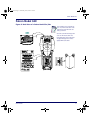
Falcon Model 34X
Falcon Model 34X
Figure 3. Back View of a Falcon Model 33x/34x
These illustrations are for illustrative purposes only. View the actual labels on the
product itself for applicable model and
safety specifications.
Some units come with Linear Imagers and
some come with Laser Scanners. The
Laser Safety Caution shown to the left will
only appear and apply to those devices
equipped with Laser Scanners.
User’s Guide
xi
2314.book Page xii Wednesday, June 9, 2004 8:30 AM
Safety Information
Advisory Statement
Use of controls, adjustments, or performance of procedures other than those specified herein may
result in hazardous visible or invisible laser light exposure.
CAUTION
Regulatory Statements
Radio Frequency Interference
This device complies with Part 15 of the FCC Rules. Operation is subject to the following two conditions:
•
This device may not cause harmful interference, and
•
This device must accept any interference received, including interference that may cause undesired operation.
This equipment has been tested and found to comply with the limits for a Class A digital device, pursuant to Part 15 of the FCC
Rules. These limits are designed to provide reasonable protection against harmful interference in a residential installation. This
equipment generates, uses and can radiate radio frequency energy and, if not installed and used in accordance with these
instructions, may cause harmful interference to radio communications. However, there is no guarantee that interference will not
occur in a particular installation. If this equipment does cause interference to radio or television reception, which can be determined by turning the equipment off and on, the user is encouraged to try to correct the interference by one or more of the following measures:
•
Reorient or relocate the receiving antenna.
•
Increase the separation between the equipment and receiver.
•
Connect the equipment into an outlet on a circuit different from which the receiver is connected.
•
Consult the dealer or an experienced radio/TV technician for help.
Canadian Compliance Statement
This Class A Digital apparatus complies with Canadian ICES-003.
Cet appareil numérique de la Classe A est confirme à la norme NMB-003 du Canada.
xii
Falcon® DOS Portable Terminals
2314.book Page xiii Wednesday, June 9, 2004 8:30 AM
Laser Safety
International Caution Statements for CLASS 11, 22,
3R3, II4, and IIA5 Laser Devices
English
PSC scanners are certified in the U.S. to conform to the requirements of DHHS/CDRH 21CFR Subchapter J and to the requirements of IEC/EN 60825-1:1998-2001.
Class 1, 2, 3R, Class II, and IIA products are not considered to be hazardous. The scanner contains internally a Visible Laser
Diode (VLD) whose emissions do not exceed the maximum limits as set forth in the above regulations. The scanner is designed
so that there is no human access to harmful laser light during normal operation, user maintenance or during prescribed service
operations.
CAUTION
If the scan pattern is a single dot when depressing the trigger, discontinue operation and return the scanner to PSC.
CAUTION
Do not attempt to open or otherwise service any components in the optics cavity. Opening or servicing any part of the optics cavity by unauthorized personnel may violate laser safety regulations. The optics system is a factory only repair item.
CAUTION
Use of optical systems with the scanner will increase eye hazard. Optical instruments include binoculars, microscopes and magnifying glasses. This does not include eye glasses worn by the user.
French
Ce scanneurs du PSC sont certifié conforme à la norme DHHS/CDRH 21CFR sous-chapitre J et à la norme IEC/EN 608251:1998-2001.
Les produits de class 1, 2, 3R, class II, et de IIA ne sont pas considérés dangereux. Le scanneur contient une diode laser visible
(VLD) dont les émissions ne dépassent pas les limites prescrites dans les normes précitées. Le scanneur est conçu de façon à
ce qu’il ne soit pas possible d’accéder à la lumière laser pendant l’utilisation normale, l’entretien par l’utilisateur et les fonctions
de maintenance prescrites.
ATTENTION
Si, quand la fonction de balayage est lancée, le diagramme de balayage est constitué d’un seul point, cesser d’utiliser le scanneur et le retourner à PSC.
ATTENTION
Ne pas essayer d’ouvrir ou de réparer les composants de la cavité optique. L’ouverture de la cavité optique ou la réparation de
ses composants par une personne non qualifiée peut entraîner le non-respect des règles de sécurité relatives au laser. Le
système optique ne peut être réparé qu’en usine.
ATTENTION
L’utilisation d’instruments optiques avec le scanneur augmente le danger pour les yeux. Les instruments optiques comprennent
les jumelles, les microscopes et les verres grossissants. Ils ne comprennent pas les lunettes portées par l’utilisateur.
1.
2.
3.
4.
5.
Class 1 applies to IEC/EN STD (Europe).
Class 2 applies to IEC/EN STD (Europe).
Class 3R applies to the Falcon 4410/4420 using ALR (Advanced Long Range) Laser, only.
Class II applies to CDRH STD (US/Canada).
Class IIA applies to CDRH STD (US/Canada).
User’s Guide
xiii
2314.book Page xiv Wednesday, June 9, 2004 8:30 AM
Laser Safety
German
Dieser Scanner ist den in den Vereinigten Staaten geltenden Vorschriften des DHHS/CDRH 21 CFR Subchapter J und den Vorschriften der IEC/EN 60825-1:1998-2001 entsprechend bescheinigt.
Produkte der Klasse 1, 2, 3R, Klasse II oder der IIA sind als ungefährlich eingestuft. Im Inneren des Scanners befindet sich eine
VLD (Visible Laser Diode), deren Ausstrahlung die in den oben genannten Vorschriften angeführten Höchstgrenzen nicht überschreitet. Die Konstruktion des Scanners garantiert, daß bei normalem Betrieb, bei Wartung durch den Benutzer oder im Laufe
planmäßiger Wartungsarbeiten kein Zugang zu schädlichem Laserlicht besteht.
VORSICHT:
Sollte das Abtastbild bei gedrücktem Auslöser aus einem einzigen Punkt bestehen, muß der Betrieb eingestellt und der Scanner
an PSC zurückgesendet werden.
VORSICHT:
Unter keinen Umständen darf versucht werden, die Komponenten im Optikhohlraum zu öffnen oder auf irgendwelche andere
Weise zu warten. Das Öffnen bzw. Warten der Komponenten im Optikhohlraum durch unbefugtes Personal verstößt gegen die
Laser-Sicherheitsbestimmungen. Das Optiksystem darf nur werkseitig repariert werden.
VORSICHT:
Die Verwendung von Optiksystemen mit diesem Scanner erhöht die Gefahr einer Augenbeschädigung. Zu optischen Instrumenten gehören unter anderem Ferngläser, Mikroskope und Vergrößerungsgläser, nicht aber die von Benutzern getragenen
Brillen.
Italian
È stato certificato che questo scanner si conforma ai requisiti della sezione J della normativa DHHS/CDRH 21CFR, e anche ai
requisiti di IEC/EN 60825-1:1998-2001.
I prodotti di Classe 1, 2, 3R, Classe II, o IIA non sono considerati pericolosi. Lo scanner contiene al suo interno un Visible Laser
Diode (VLD), diodo laser visibile, le cui emissioni non eccedono i limiti stabiliti dalle normative sunnominate. Lo scanner è progettato in modo che non ci sia alcun accesso alla luce dannosa del laser nel corso di uso normale, di manutenzione da parte
dell’utente o durante la manutenzione periodica stabilita.
ATTENZIONE
Se, quando si preme l’azionamento, il pattern di scansione è un punto singolo, interrompere l’operazione e riportare lo scanner a
PSC .
ATTENZIONE
Non tentare di accedere allo scomparto contenete i componenti ottici o di farne la manutenzione. L’apertura dello scomparto, o la
manutenzione di qualsiasi parte ottica da parte di personale non autorizzato, potrebbe violare le norme della sicurezza. Il
sistema ottico può essere riparato solamente alla fabbrica.
ATTENZIONE
L’uso di strumenti ottici assieme allo scanner può aumentare il pericolo di danno agli occhi. Tali strumenti ottici includono cannocchiali, microscopi e lenti di ingrandimento. Essi non includono gli occhiali indossati dall’utente.
Danish
Denne scanner opfylder de amerikanske krav stillet i "DHHS/CDRH 21CFR Subchapter J" og opfylder også de krav, der stilles i
IEC/EN 60825-1:1998-2001.
Klasse 1, 2, 3R, klasse II eller klasse IIA produkter anses for at være sikre. Scanneren indeholder en Visible Laser Diode (VLD),
der ikke overskrider maksimumgrænserne, som beskrevet i ovenstående reglement. Scanneren er konstrueret, så der ikke er
nogen menneskelig kontakt medskadelige niveauer af laserbestråling under normal brug, normal vedligeholdelse eller under
foreskrevet servicering.
ADVARSEL
Hvis scanningmønsteret er et enkelt punkt, når triggeren indtrykkes, skal betjening ophøre og scanneren returneres til PSC.
xiv
Falcon® DOS Portable Terminals
2314.book Page xv Wednesday, June 9, 2004 8:30 AM
International Caution Statements for CLASS 1, 2, 3R, II, and IIA Laser Devices
ADVARSEL
Forsøg ikke at åbne eller reparere komponenter i det optiske hulrum. Uautoriseret åbning eller reparation af komponenter i det
optiske hulrum kan være en overtrædelse af lasersikkerhedsregulativer. Det optiske system må udelukkende repareres as PSC.
ADVARSEL
Anvendelse af optiske systemer med scanneren øger risikoen for øjenskader. Optiske instruments omfatter kikkerter, mikroskoper og lupper. Det omfatter ikke anvendelse af almindelige briller.
Dutch
Deze scanner is in de V.S. goedgekeurd en voldoet aan de vereisten van DHHS/CDRH 21CFR Subchapter J een aan de vereisten van IEC/EN 60825-1:1998-2001.
Producten van klasse 1 ,2, 3R, klasse II en IIA worden niet geacht gevaarlijk te zijn.
De scanner bevat een inwendige Visible Laser Diode (VLD) waarvan de emissies de maximumgrenzen van bovenstaande reglementen niet overschrijden.
De scanner is zo ontworpen dat men bij normaal gebruik, onderhoud of tijdens het uitvoeren van de voorgeschreven onderhoudswerkzaamheden niet aan schadelijke niveaus wordt blootgesteld.
WAARSCHUWING
Als het scanpatroon bij het overhalen van de trekker een enkele stip is, stop dan onmiddellijk en stuur de scanner terug naar
PSC.
WAARSCHUWING
Probeer niet om onderdelen in de opticaruimte te openen of er onderhoud aan uit te voeren. Het openen of onderhouden van
delen in de opticaruimte door onbevoegd personeel kan een inbreuk vormen op de laserveiligheidsreglementen. Het opticasysteem mag alleen in de fabriek worden gerepareerd.
WAARSCHUWING
Het gebruik van optische systemen samen met de scanner vergroot het risico voor de ogen. Optische instrumenten zijn onder
andere binoculairs, microscopen en vergrootglazen, maar niet de bril die de gebruiker draagt.
Swedish
Denna scanner uppfyller de amerikanska kraven DHHS/CDRH 21CFR Subchapter J samt kraven i IEC/EN 60825-1:1998-2001.
Produkter i Klass 1, 2, 3R, Klass II och IIA anses ej farliga. Scannern är utrustad med en intern, synlig laserdiod (Visible Laser
Diode - VLD) vars emission inte överstiger max. värdena i ova stående säkerhetsföreskrifter. Scannern har konstruerats så att
personer vid normal användning, bruksunderhåll och föreskriven service inte utsätts för skadlig laserstrålning.
VAR FÖRSIKTIG
Om scanningsmönstret är en enda punkt när du trycker på avtryckaren, ska du avbryta användningen och ta scannerna tillbaka
till PSC.
VAR FÖRSIKTIG
Försök inte öppna eller reparera komponenter i den optiska kamaren. Om icke auktoriserad personal öppnar eller reparerar
delar i den optiska kammaren, kan detta strida mot säkerhetsföreskrifterna för laserutrustning. Det optiska systemet får endast
repareras på fabriken.
VAR FÖRSIKTIG
Användning av optiska system med scannern ökar risken för ögoskada. Optiska instrument inkluderar kikare, mikroskop och förstoingsglas, men inte användarens glasögon.
Finnish
Tämä tutkain on hyväksytty Yhdysvalloissa vastaamaan DHHS/CDRH 21CFR Subchapter J luokka 60825-1:1998-2001 IEC/ENvaatimuksia.
User’s Guide
xv
2314.book Page xvi Wednesday, June 9, 2004 8:30 AM
Laser Safety
Luokka 1, 2, 3R, Luokka II tai IIAtuotteiden ei katsota olevan vaarallisia. Tutkain sisältää sisäisen näkyvän laserdiodin (Visible
Laser Diode (VLD), jonka päästöt eivät ylitä yllä olevien säädösten asettamia maksimirajoja. Tutkain on suunniteltu siten, etteivät
ihmiset altistu vaaralliselle lasersäteilylle normaalikäytön, käyttäjän suorittaman huollon tai ohjeiden mukaisten huoltotoimenpiteiden aikana.
VAROITUS
Jos skannauskuva on yksittäinen piste laukaisinta painettaessa, keskeytä käyttö ja palauta tutkain PSC:lle.
VAROITUS
Älä yritä avata tai muuten huoltaa mitään rakenneosia optisessa osassa. Valtuuttamattoman henkilöstön suorittaman optisen
osan avauksen tai huoltotoimen voidaan katsoa olevan rikkomus lasersuojaohjeita vastaan. Optisen järjestelmän saa korjata ainoastaan tehtaalla.
VAROITUS
Mikäli optisia järjestelmiä käytetään tutkainmen kanssa, silmille aiheutuva vaara lisääntyy. Optiset kojeet käsittävät kiikarit, mikroskoopit ja suurennuslasit. Käyttäjän silmälasit eivät kuulu tähän ryhmään.
Norwegian
Denne skanneren er godkjent i USA i samsvar med retningslinjene for DHHS/CDRH 21CFR, avsnitt J, og til IEC/EN 608251:1998-2001.
Produkter i klasse 1 2, 3R, klasse II eller IIA ansees ikke som helsefarlige. Skanneren inneholder en innvendig, synlig laserdiode
(VLD, Visible Laser Diode), som ikke overskrider maksimalgrensene som er fastsatt i retningslinjene ovenfor. Skanneren er konstruert, slik at personer ikke utsettes for farlige doser med laserstråler ved normal drift, brukers vedlikehold eller ved foreskrevet
service.
OBS!
Hvis skanningsmønsteret består av én enkel prikk når utløseren trykkes inn, skal driften stanses, og skanneren settes tilbake til
PSC.
OBS!
Prøv ikke å åpne eller på noen måte utføre service på noen av delene i det optiske kammeret. Ved å åpne eller utføre service på
noen av delene i det optiske kammeret av uautorisert personell, kan krenke forskriftene for lasersikkerhet. Optikksystemet skal
bare repareres på fabrikken.
OBS!
Bruk av optiske systemer med skanneren kan innebære høyere fare for øynene. Optiske instrumenter innbefatter, kikkerter, mikroskop og forstørrelsesglass. Dette omfatter ikke briller som brukeren har
på seg.
Portuguese
Este scanner foi certificado nos EUA para atender os requisitos do subcapítulo J do DHHS/CDRH 21 CFR e os requisitos do
IEC/EN 60825-1:1998-2001.
Os produtos da Classe 1, 2, 3R, Classe II ou IIA não são considerados perigosos. O scanner contém internamente um Diodo de
Laser Visível (VLD - Visible Laser Diode) cujas emissões não ultrapassam os limites definidos nos regulamentos mencionados
acima. O scanner foi projetado de maneira que não exista acesso humano à luz de laser nociva durante a operação normal,
manutenção pelo usuário ou durante as operações recomendadas de serviço.
CUIDADO
Se ao pressionar o gatilho a luz do laser for um único ponto, interrompa a operação e devolva o scanner à PSC.
CUIDADO
Não tente abrir ou consertar qualquer componente da cavidade óptica. A abertura ou manutenção de qualquer peça da cavidade óptica por pessoal não autorizado pode infringir os regulamentos de segurança do laser. O sistema óptico só deve ser
reparado na fábrica.
CUIDADO
O uso de instrumentos ópticos com o scanner aumenta o risco para a visão. Incluem-se entre os instrumentos ópticos os
binóculos, microscópios e lentes de aumento. Não se incluem os óculos usados pelo usuário.
xvi
Falcon® DOS Portable Terminals
2314.book Page xvii Wednesday, June 9, 2004 8:30 AM
International Caution Statements for CLASS 1, 2, 3R, II, and IIA Laser Devices
Spanish
Este escáner está certificado en los EE.UU. porque reúne los requisitos DHHS/CDRH 21CFR Sección J y los requisitos de IEC/
EN 60825-1:1998-2001.
Los productos de Clase 1, 2, 3R, Clase II, o IIA no se consideran como peligrosos. El escáner tiene en su interior un Diodo
Láser Visible (VLD) cuyas emisiones no exceden los límites máximos fijados en los reglamentos mencionados anteriormente. El
escáner está diseñado de modo que las personas no tengan acceso a la luz láser peligrosa durante la operación normal, el
mantenimiento por parte del usuario o durante las operaciones de servicio prescritas.
PRECAUCIÓN
Si al oprimir el interruptor, el patrón de exploración es un solo punto, discontinúe el uso y devuelva el escáner a PSC.
PRECAUCIÓN
No intente abrir o de ninguna manera dar servicio a ninguno de los componentes del receptáculo óptico. Abrir o dar servicio a
las piezas del receptáculo óptico por parte del personal no autorizado podría ser una violación a los reglamentos de seguridad.
El sistema óptico se puede reparar en la fábrica solamente.
PRECAUCIÓN
El uso de sistemas ópticos con el escáner aumentará el riesgo de daños oculares. Los instrumentos ópticos incluyen binoculares, microscopios y lupas. Esto no incluye los lentes recetados usados por el usuario.
Chinese
User’s Guide
xvii
2314.book Page xviii Wednesday, June 9, 2004 8:30 AM
Laser Safety
Japanese
xviii
Falcon® DOS Portable Terminals
2314.book Page xix Wednesday, June 9, 2004 8:30 AM
Preface
Overview ................................................................. xiv
Falcon Model Numbers ........................................... xiv
Style Conventions ................................................... xvi
Document Conventions .......................................xvi
Keys and Keystroke Conventions ..........................xvi
2314.book Page xx Wednesday, June 9, 2004 8:30 AM
Preface
Overview
This book provides information about Falcon DOS portable data terminals
for first-time users. The focus of this manual is:
•
Basic use of the Falcon
•
Entering data from the Falcon keypad
•
Viewport panning and contrast
•
Use of a laser to scan bar codes
•
The Falcon Dock
•
The Falcon 4-Slot Dock
•
The Falcon Vehicle Mount Powered Dock
For additional information about Falcon DOS portable data terminals, including instructions on transferring files from a Falcon to a PC, refer to the Falcon
DOS Portable Data Terminals Advanced User’s Guide.
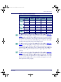
Falcon Model Numbers
Falcon DOS portable data terminals are handheld computers designed for data
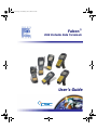
collection. The product title, Falcon, refers to any or all of the DOS portable
models identified in Table 1 on page xxi.
Where information in this manual applies only to specific models, those models are clearly identified by the model icon as shown in the first column of
Table 1 on page xxi.
The Falcon DOS portable line includes 8-line and 16-line models. Both the 8line and the 16-line Falcon models are available in batch and wireless (radio
frequency, or RF) configurations. Wireless models provide instant communication of data between the unit and a host computer.
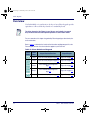
The 31X icon refers to both the Falcon 310 and the Falcon 315. As Table 1 on
notes, the Falcon 310 is a batch portable model and the Falcon 315 is
an RF portable model. On the cover of this manual, the Falcon 31X is represented by the Falcon 315, in the lower left corner, with an 8-line display screen.
page xxi
xx
Falcon® DOS Portable Terminals
2314.book Page xxi Wednesday, June 9, 2004 8:30 AM
Falcon Model Numbers
Table 1: Falcon Portable Models
Falcon Portable Models
Model
Model
Number
8-Line
Display
310
315
320
325
330
335
340
345
16-Line
Display
Batch
Portable
RF Portable
The 32X icon refers to both the Falcon 320 and the Falcon 325. As Table 1 on
page xxi notes, the Falcon 320 is a batch portable model and the Falcon 325 is
an RF portable model. The Falcon 32X has many features in common with the
Falcon 33X. These models are often grouped together throughout this manual.
On the cover of this manual, the Falcon 32X is represented by the Falcon 325,
second from the upper left, with a 16-line display screen.
The 33X icon refers to both the Falcon 330 and the Falcon 335. As Table 1 on
page xxi notes, the Falcon 330 is a batch portable model and the Falcon 335 is
an RF portable model. The Falcon 33X model has many features in common
with the Falcon 32X model. On the cover of this manual, the Falcon 330 portable is the smaller, ergonomic model shown in the upper right corner of the
grouping.
The 34X icon refers to both the Falcon 340 and the Falcon 345. As Table 1 on
page xxi notes, the Falcon 340 is a batch portable model and the Falcon 345 is
an RF portable model. The Falcon 34X introduces the pistol grip. This model
operates in every other way identically to the Falcon 33X. On the cover of this
manual, the Falcon 340 portable is the one with the pistol grip, shown in the
lower right corner of the grouping.
User’s Guide
xxi
2314.book Page xxii Wednesday, June 9, 2004 8:30 AM
Preface
Style Conventions
Document Conventions
Formatting conventions are used throughout this guide as a method of providing consistency for notes, cautions, and warnings.
Notes appear throughout the manual to provide additional information on a topic,
including technical details, exceptions to instructions and other pertinent information. These notes are identified by the notepad symbol to the left.
Cautions appear when there is information that could potentially cause the system to operate incorrectly.
CAUTION
Keys and Keystroke Conventions
Portable keys and keystroke conventions are used throughout this manual to
identify the difference between a key on the portable and keystrokes input by
the user. Brackets such as: “<Scan>” indicate a key on the Falcon Portable.
Data or keystrokes entered by the user are printed in a monospaced
typeface.
xxii
Falcon® DOS Portable Terminals
2314.book Page 1 Wednesday, June 9, 2004 8:30 AM
1
Falcon Basics
Turning the Falcon On and Off ............................... 10
First-Time Use ..................................................... 10
“Please Wait” Messages ......................................... 10
Power Supplies ......................................................... 11
Batteries ................................................................... 11
Electrical Rating ................................................... 11
Auto-Shutoff ........................................................ 11
Low-Battery Warning ........................................... 11
Replacement Batteries .......................................... 12
Battery Disposal ................................................... 12
Replacing the Batteries ......................................... 13
Removing the Pistol Grip ........................................ 18
Replacing the Pistol Grip with the Hand-Strap .... 19
The Serial Port ......................................................... 20
The Falcon Applications .......................................... 20
2314.book Page 2 Wednesday, June 9, 2004 8:30 AM
Falcon Basics
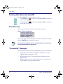
Turning the Falcon On and Off
Press the <Power> key to turn the unit on or off.
•
) for Falcon models 31X and 32X is located at the
The <Power> key (
top left of the keypad.
•
) for Falcon models 33X and 34X is located at the
The <Power> key (
bottom left of the keypad.
First-Time Use
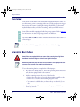
The first time the Falcon is turned on, this message may appear:
Figure 4. Start-up message
Initial power-up or
critical data loss.
Drive D formatted.
Press any key...
The message appears with normal operation and does not indicate a problem.
Press the <ENTER> key to continue booting up.
This message will also appear when new or recharged batteries are placed in the
unit after the backup battery has been drained.
“Please Wait” Messages
The Falcon performs the operations specified by the type of PC card installed.
2
•
During these operations, the unit displays a message in reverse video
indicating that it is powering on or off.
•
When turning the unit on, wait until the message disappears before
using the unit.
•
When turning the unit off, to replace the batteries, wait until the message disappears before removing the batteries.
Falcon® DOS Portable Terminals
2314.book Page 3 Wednesday, June 9, 2004 8:30 AM
Power Supplies
Power Supplies
Only PSC power supplies, batteries, chargers, and docks should be used with
Falcon PDTs. The use of other power supplies, batteries, chargers, and docks will
void the warranty of any and all related units and batteries.
Refer to page 57 for more information on the Falcon Power Adaptor.
Batteries
PSC recommends annual replacement of rechargeable battery packs to ensure
maximum performance.
Electrical Rating
NiCD or NiMH batteries = 3.6 VDC /1600mAh or 2000mAh.
Auto-Shutoff
The Falcon has an automatic-shutoff feature that helps conserve battery life
while not in use.
•
When a specified amount of time has passed since a key or a trigger has
been pressed, the Falcon turns itself off.
•
All data in memory is maintained.
•
Press the power button to turn the unit back on.
Low-Battery Warning
When the batteries have lost most of their charge, an empty battery icon
appears at the top right corner of the Falcon screen. Refer to the icons on the
left for the specific icon for each model.
User’s Guide
•
The Falcon also can be programmed to emit a beep at intervals when the
battery is low.
•
The backup battery will protect all data in memory while the other batteries are out of the unit.
3
2314.book Page 4 Wednesday, June 9, 2004 8:30 AM
Falcon Basics
After recharging or replacing the batteries and turning the Falcon back on, the
unit will return to the application operating when it was turned off.
Replacement Batteries
Replace the Falcon’s NiCD or NiMH battery pack only with a NiCD or NiMH battery
pack supplied by a PSC reseller.
CAUTION
Falcon batteries are available in rechargeable, easy-to-replace nickel cadmium
(NiCD) or nickel metal-hydride (NiMH) battery packs.
•
Falcon models 31X use three standard AA alkaline batteries, NiCD battery packs, or NiMH battery packs.
•
For Falcon models 32X, only NiMH battery packs are recommended.
•
For Falcon models 33X and 34X models, only NiMH battery packs are
recommended. Individual alkaline batteries are not compatible with
these models.
The Falcon also has a built-in lithium backup battery that temporarily saves
data when the replaceable batteries lose their charge. The lithium backup battery is not accessible by the user.
A battery icon, shown at the left, is displayed at the top right corner of the
viewport when the Falcon models 32X, 33X, and 34X are running with a
charged battery.
Battery Disposal
Recycle NiCD or NiMH Batteries.
CAUTION
4
Do not throw NiCD or NiMH in the trash.
Falcon® DOS Portable Terminals
2314.book Page 5 Wednesday, June 9, 2004 8:30 AM
Batteries
Replacing the Batteries
When the empty-battery icon appears or the warning beep is heard, turn off
the Falcon and recharge or replace the batteries as soon as possible.
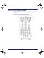
Replaceable batteries are located in a compartment in the back of the Falcon.
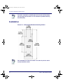
Refer to Figure 5 on page 6, Figure 6 on page 7, and Figure 7 on page 9 for diagrams of the different Falcon models.
Turn the Falcon portable off before changing the batteries. Removing batteries while
the unit is turned on can result in the loss of stored data.
CAUTION
Falcon Models 31x and 32x
To replace the batteries for Falcon models 31X and 32X, complete the following
steps:
1. Turn the Falcon off.
2. Detach the elastic hand-strap on the back of the Falcon by pulling its
hook out of the holder near the base.
3. Firmly press the tab on the battery-compartment cover up until the
cover is released from the body of the unit.
• A symbol on the body indicates the direction in which to press the
tab.
4. Pull the end of the exposed plastic ribbon in the battery compartment
until the batteries pop out.
5. Lay the plastic ribbon along the bottom of the battery compartment
with the end sticking out.
6. Find the positive (+) and negative (-) symbols on the NiCD or NiMH
Battery Pack’s label.
• For Alkaline Batteries, insert in the positions indicated by the diagram inside the compartment. Skip steps 7– 8.
7. With the label side out, tilt the positive end of the pack into the upper
end of the battery compartment.
User’s Guide
5
2314.book Page 6 Wednesday, June 9, 2004 8:30 AM
Falcon Basics
8. Firmly press the negative end until it is fully inserted into the battery
compartment.
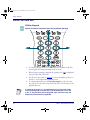
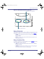
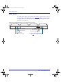
Figure 5. Back View of Falcon Models 31x and 32x
Battery-compartment cover
Tab
Battery Pack
PSC
00-862-00
NiCD BATTERY
E9642W
+
NiCD Battery
Pack Label
Strap-hook holders
Serial Port
9. Place the plastic ribbon underneath the battery-compartment cover.
10. Replace the battery-compartment cover by sliding it into place.
11. Replace the hand-strap hook in its holder.
The Falcon 32X will not function unless the battery-compartment cover is in place
and securely latched.
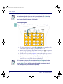
Falcon Models 33x
To replace the batteries for Falcon models 33X, complete the following steps:
1. Turn the Falcon off.
2. Detach the elastic hand strap on the back of the Falcon by releasing its
hook from the hand-strap connector at the base of the unit.
6
Falcon® DOS Portable Terminals
2314.book Page 7 Wednesday, June 9, 2004 8:30 AM
Batteries
3. Turn the dial counter-clockwise to release the battery compartment
cover.
4. Pull the end of the exposed plastic ribbon in the battery compartment
until the batteries pop out.
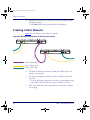
Figure 6. Back View of Falcon Model 33x
Dial
Battery
compartment
cover
Upper Hand -Strap Holder
Hand Strap
Plastic Ribbon
NiMH Battery Pack
IR Port
Lower Hand Strap connections
5. Lay the plastic ribbon along the bottom of the battery compartment
with the end sticking out.
6. Find the positive (+) and negative (-) symbols on the NiMH Battery
Pack’s label.
7. With the label side out, tilt the positive end of the pack into the upper
end of the battery compartment.
8. Firmly press the negative end until it is fully inserted into the battery
compartment.
9. Place the plastic ribbon underneath the battery-compartment cover.
User’s Guide
7
2314.book Page 8 Wednesday, June 9, 2004 8:30 AM
Falcon Basics
10. Replace the battery-compartment cover by inserting the bottom tab into
the slot and rotating the cover latch in a clockwise direction.
11. Replace the hand-strap hook on the connector at the base of the unit.
The Falcon 33X will not function unless the battery-compartment cover is in place
and securely latched.
The battery pack should not be replaced in a dirty or harsh environment. When the
battery compartment cover is off, dust or moisture can potentially cause damage.
Falcon models 33x and 34x will not function unless the battery-compartment cover
is in place and securely latched.
Falcon Models 34x
To replace the batteries for Falcon model 34X, complete the following steps:
1. Turn the Falcon off.
2. If using the hand-strap rather than the pistol grip, detach the elastic
hand-strap by releasing its hook from the hand-strap connector at the
base of the unit.
3. Turn the cover latch dials to release the battery compartment cover.
Refer to Figure 8 on page 10 for the location of the dials.
• Using the lever, turn the left dial clockwise.
• Using the lever, turn the right dial counter-clockwise.
4. Pull the end of the exposed plastic ribbon in the battery compartment
until the batteries pop out.
5. Lay the plastic ribbon along the bottom of the battery compartment
with the end sticking out.
6. Find the positive (+) and negative (-) symbols on the NiMH Battery
Pack’s label.
7. With the label side out, tilt the positive end of the pack into the upper
end of the battery compartment.
8. Firmly press the negative end until it is fully inserted into the battery
compartment.
9. Place the plastic ribbon underneath the battery-compartment cover.
8
Falcon® DOS Portable Terminals
2314.book Page 9 Wednesday, June 9, 2004 8:30 AM
Batteries
Figure 7. Back View of Falcon Model 34x
Dials
Pistol Grip
Battery
compartment
cover
Trigger
NiMH Battery Pack
Lower Hand Strap connections
IR Port
10. Replace the battery-compartment cover by inserting the bottom tab into
the slot.
11. Rotate the latch dial levers on the battery compartment cover towards
the base of the unit. Refer to Figure 8 on page 10.
• Using the lever, turn the left dial counter-clockwise.
• Using the lever, turn the right dial clockwise.
12. If using the hand-strap rather than the pistol grip, replace the hand-strap
hook on the connector at the base of the unit.
The Falcon 34X will not function unless the battery-compartment cover is in place
and securely latched.
User’s Guide
9
2314.book Page 10 Wednesday, June 9, 2004 8:30 AM
Falcon Basics
Removing the Pistol Grip
The pistol grip on the Falcon 34X is removable.
To remove the pistol grip on the Falcon 34X (refer to Figure 8 on page 10)
complete the following steps:
1. Turn the Falcon off.
2. Remove the screws located just above the battery cover’s latch dials.
3. Grasp the pistol grip and lift the grip out of its seat on the Falcon.
Figure 8. Removing the Pistol Grip on a Falcon Model 34x
Pistol Grip
Screws
Washers
Battery
Cover Dials
Trigger
Battery Cover
Protective
Diaphragm
Laser
10
Falcon® DOS Portable Terminals
2314.book Page 11 Wednesday, June 9, 2004 8:30 AM
Removing the Pistol Grip
Replacing the Pistol Grip with the Hand-Strap
To replace the pistol grip on the Falcon 34X with its hand-strap (refer to Figure
9 on page 11) complete the following steps:
1. Insert the top tab of the hand-strap cover into the slot at the top of the
pistol grip recess.
Figure 9. Replacing the Pistol Grip with a Hand-Strap
Screws
Hand Strap Clip
Washers
Hand Strap
Battery Cover
Pistol Grip Cover
Dials
Laser
2. Replace the screws located just above the battery cover’s latch dials.
3. Connect the hand-strap hook onto its connector at the base of the Falcon unit.
User’s Guide
11
2314.book Page 12 Wednesday, June 9, 2004 8:30 AM
Falcon Basics
The Serial Port
The Falcon models 31X and 32X have a port for serial communications with a
PC. The port is located at the base of the Falcon unit (refer to Figure 10). Designated as COM1, it is a 10-pin telephone-style jack providing a standard
RS-232 connection.
When the Falcon is connected with a serial cable, the port allows communications with a host computer or any serial device, such as a printer or modem.
The serial port also provides a connection for communications and battery
recharging in the Falcon Dock and Falcon 4-Slot Dock.
Figure 10. The Serial Port on the Falcon 31X and 32X
The Falcon Applications
When shipped from the factory, every Falcon unit is programmed with several
applications collectively known as PAL2. If the Falcon has been customized, it
may be programmed with other (or additional) applications.
For information on using PAL2, see the Falcon Portable Applications
Library User’s Guide. When using another application, contact the system
administrator for instructions.
12
Falcon® DOS Portable Terminals
2314.book Page 13 Wednesday, June 9, 2004 8:30 AM
2
Falcon Keypads
Overview .......................................................................................... 22
Falcon 31x 41-Key Keypad .............................................................. 23
Comparing Falcon 31x 41-Key Keypad and PC Keyboard .............23
Input Modes .................................................................................24
International Characters .................................................................26
Falcon 32x 57-Key Keypad .............................................................. 27
Comparing Falcon 32x 57-Key Keypad with PC Keyboard ............27
Input Modes .................................................................................29
International Characters .................................................................29
Repeating Keystrokes .....................................................................30
Falcon 33x/34x 25-Key Keypad ....................................................... 30
Comparing Falcon 25-Key Keypads with PC Keyboards ................31
Icons and Input Modes ..................................................................32
Double Action Key Mode ..............................................................33
Falcon 33x/34x 38-Key Keypad ....................................................... 35
Comparing Falcon 38-Key Keypads with PC Keyboards ................36
Icons and Input Modes ..................................................................37
Double Action Key Mode ..............................................................38
Double Strike Mode .......................................................................38
Press and Wait Mode ......................................................................38
International Characters .................................................................39
Falcon 34x 48-Key Keypad .............................................................. 40
Comparing Falcon 48-Key Keypads with PC Keyboards ................41
Icons and Input Modes ..................................................................42
Repeating Keystrokes .....................................................................42
2314.book Page 14 Wednesday, June 9, 2004 8:30 AM
Falcon Keypads
Overview
Used individually or in combination, the keys of most Falcon keypads provide
equivalents to almost all the keys found on a standard keyboard.
The 25-key keypads of the Falcon 33x and 34x are used primarily for numeric
entry and do not have the same keyboard equivalents as other Falcon models.
For your convenience, this chapter is organized by Falcon keypad type, rather than by features and functions.
Refer to Table 2 to determine the location of the information and diagrams specific to the
Falcon keypad you have. Go to the section that applies to your Falcon unit.
Table 2: Falcon Models and Keypads
Falcon
Model
14
Number
of Keys
Keypad Features/Functions
Keypad Diagram
41 keys
Falcon 31x 41-Key Keypad on page 15
Figure 11 on page 15
57 keys
Falcon 32x 57-Key Keypad on page 19
Figure 12 on page 19
25 keys
Falcon 33x/34x 25-Key Keypad on
page 22
Figure 13 on page 23
38 keys
Falcon 33x/34x 38-Key Keypad on
page 27
Figure 14 on page 27
48 keys
Falcon 34x 48-Key Keypad on page 32
Figure 15 on page 32
Falcon® DOS Portable Terminals
2314.book Page 15 Wednesday, June 9, 2004 8:30 AM
Falcon 31x 41-Key Keypad
Falcon 31x 41-Key Keypad
The Falcon 31x is an 8-line portable data terminal with 41 keys.
Figure 11. The Keypad for Falcon 31X Models
Comparing Falcon 31x 41-Key Keypad and PC Keyboard
The keys in Table 3 appear on a standard PC computer keyboard but are not
used on the Falcon 31x:
Table 3: Standard Keyboard Keys not on the Falcon 31x
Standard Keyboard Keys not on the Falcon 31x
<F11>
Left <Shift>*
<Scroll Lock>
<Caps Lock>*
<Pause/Break>
Right <Ctrl>
Right <Alt>
<Print Screen>/
<SysReq>
Grey Numeric Number Keys
Right <Shift>*
<Num Lock>
<F12>
* The Falcon’s <Caps> key provides the functions of these keys.
User’s Guide
15
2314.book Page 16 Wednesday, June 9, 2004 8:30 AM
Falcon Keypads
The Falcon 31x has some keys that are not found on a PC keyboard. These
keys are shown in Table 4. Page numbers indicate where to find more information about the keys.
Table 4: Falcon 31X Keys Not Found on a Standard Keyboard
Key
Default Use
<Alpha>
Toggles the Falcon between Alpha mode and Normal mode
(page 25).
<Caps>
When pressed and released, toggles Caps mode on and off; when
held down, acts equivalently to the <Shift> key on a standard computer keyboard (page 17).
<Dark>
Darkens the background of the viewport (page 41).
<FN 1>
Outputs the blue symbol or activates the function (<F1> –<F10>)
above the next key pressed (page 16).
<FN 2>
Outputs the black symbol above the next key pressed (page 16).
<INTL>
Outputs an international character generated by the combination of
the next two key presses (page 18).
<Lamp> (
)
<Light >
<Power> (
Turns the backlight on and off in the viewport (page 42).
Lightens the background of the viewport (page 41).
)
Turns the Falcon on and off (page 2).
<Swap>
Switches the assigned actions of the right and left laser triggers
(page 49).
Left laser trigger
Operates the Falcon laser or an attached bar code reader (can be
reprogrammed as a keypad key, page 49)*.
Right laser trigger
Same as the <Alpha> key (can be reprogrammed as a laser trigger
or a keypad key, page 49)*.
* For information about reprogramming triggers, refer to the Falcon DOS Portable Data Terminal Advanced User’s Guide.
Input Modes
During operations that require use of a disk drive, a disk icon (shown at left)
appears on the right side of the viewport. This indicates that the unit is busy.
Wait until the icon disappears before continuing to use the unit.
16
Falcon® DOS Portable Terminals
2314.book Page 17 Wednesday, June 9, 2004 8:30 AM
Falcon 31x 41-Key Keypad
The current input mode determines key functions on the Falcon 31x. The
shape of the cursor on the Falcon 31x in the viewport indicates the current
input mode.Input modes and corresponding cursors are described in Table 5
on page 17.
Table 5: Input Modes, Key Sequences and Cursors
Input Mode/
Key Sequence
Cursor
Result of Keypress
Type 1—Remains in effect after each keypress until discontinued by user.
Normal
Outputs the white number or symbol on the key, or performs
an action (e.g., moves left).
<Alpha>
Outputs the yellow letter on the key (lowercase unless used
with Caps mode).
<Caps>
(Alpha Mode)
Outputs the uppercase yellow letter on the key.
Type 2—Affects only a single keypress or combination of key presses.
Function 1
Outputs the blue symbol or function above the key.
Function 2
Outputs the black symbol above the key.
Control <CTL>
Outputs the control meaning for alphanumeric or function
keys.
Alternate
<ALT>
Outputs the alternate meaning for alphanumeric or function
keys.
International
<INTL>
Outputs a character from the international character set
(page 18).
Working with Input Modes
The color coding of the keys and characters on the Falcon 31X reflects input
mode functions.
•
The yellow <Alpha> key works with the yellow letters on the other keys.
•
The blue <FN 1> key works with the functions (<F1> – <F10>) and the
blue characters printed above some of the keys.
•
The black <FN 2> key works with the black characters or operations
printed above some of the keys.
For most applications, the letters and numbers are all that are needed.
User’s Guide
17
2314.book Page 18 Wednesday, June 9, 2004 8:30 AM
Falcon Keypads
•
Input letters by pressing the <Alpha> key (to turn on Alpha mode) and
pressing the keys for the letters.
•
Press the <Caps> key while in Alpha mode for uppercase letters.
•
Press the <Alpha> key again to return to the Normal mode.
•
In Normal mode, numbers and punctuation characters can be selected by
pressing the appropriate key.
A type-1 mode can be temporarily overridden without actually changing the
mode. For example, when entering numbers in Normal mode, to type a letter:
•
Hold down the <Alpha> key while pressing the key for that letter.
•
Release the <Alpha> key; the Falcon 31x will still be in Normal mode.
•
Use the <Caps> key the same way to enter an uppercase letter without
changing to Caps mode.
International Characters
The international character set contains letters and symbols commonly used in
Western European languages. Enter international characters by using the following key sequence: Intl accent letter
•
The accent is a character from the Accent or Letter column of Table 6 on
page 18.
•
The letter is a character from the Letter column in the same row.
Table 6: Falcon 31X International Character Keys
18
Accent or Letter
Letter
International Characters
‘ (apostrophe)
a, e, i, o, u, E
á, é, í, ó, ú, É
`
a, e, i, o, u
à, è, ì, ò, ù
^
a, e, i, o, u
â, ê, î, ô, û
:
a, e, i, o, u, y, A, O, U
ä, ë, ï, ö, ü, ÿ, Ä, Ö, Ü
@
a, A
å, Å
None
c or C
ç or Ç
None
n or N
ñ or Ñ
~
n or N
ñ or Ñ
s
s
ß
a
e
æ
A
E
Æ
Falcon® DOS Portable Terminals
2314.book Page 19 Wednesday, June 9, 2004 8:30 AM
Falcon 32x 57-Key Keypad
?
?
¿
!
!
¡
FN 1 + $
None
£
FN 2 + $
None
¥
, (comma)
c or C
ç or Ç
Falcon 32x 57-Key Keypad
The Falcon 32x is a 16-line portable data terminal with 57 keys.
Because they have more keys, Falcon 32x models have fewer possible outputs
from a single key and are easier for a beginner to use.
Figure 12. The Keypad for Falcon 32X Models
Comparing Falcon 32x 57-Key Keypad with PC Keyboard
The keys in Table 7 appear on a standard PC computer keyboard but are not
used on the Falcon 32x:
User’s Guide
19
2314.book Page 20 Wednesday, June 9, 2004 8:30 AM
Falcon Keypads
Table 7: Standard PC Keyboard Keys not on the Falcon 32x
Standard PC Keyboard Keys not on the Falcon 32x
<Home>
<Pg Up>
<End>
<Pg Down>
<F11>
Left <Shift>*
<Num Lock>
<F12>
<Scroll Lock>
<Caps Lock>*
<Pause/Break>
Right <Ctrl>
Right <Shift>*
Right <Alt>
<Print Screen>/
<SysReq>
Grey Numeric Number Keys
* The Falcon’s <Caps> key provides the functions of these keys.
The Falcon 32x has some keys that are not found on a PC keyboard. These
keys are shown in Table 8. Page numbers indicate where to find more information about the keys.
Table 8: Falcon 32X Keys Not on a Standard Keyboard
Key
Default Use
<Caps>
When pressed and released, toggles Caps mode on and off; when
held down, acts equivalently to the <Shift> key on a standard computer keyboard (page 21).
<FN>
Outputs the symbol or activates the function (<F6> –<F10>)
above the next key pressed (page 21).
<Dark>
Darkens the background of the viewport (page 41).
<INTL> (
Outputs an international character generated by the combination of
the next two key presses (page 31).
)
<Lamp> (
)
<Light>
Turns the backlight on and off in the viewport (page 42).
Lightens the background of the viewport (page 41).
<Power> (
)
Turns the Falcon on and off (page 2).
<SWP> (Swap)
Switches the assigned actions of the right and left laser triggers
(page 49).
Left laser trigger
Operates the Falcon laser or an attached bar code reader; can be
reprogrammed as a keypad key (page 49)*.
Right laser trigger
Same as the <FN> key; can be reprogrammed as a laser trigger or
a keypad key (page 49)*.
Viewport Panning
Mode (
)
Use <FN> to toggle the viewport panning mode on or off.
* For information about reprogramming triggers, refer to the Falcon DOS Portable Data Terminal Advanced User’s Guide.
20
Falcon® DOS Portable Terminals
2314.book Page 21 Wednesday, June 9, 2004 8:30 AM
Falcon 32x 57-Key Keypad
Input Modes
During operations that require use of a disk drive, a disk icon (shown at left)
appears on the right side of the viewport. This indicates that the unit is busy.
Wait until the icon disappears before continuing to use the unit.
The current input mode determines key functions on the Falcon 32x. The
input modes and corresponding icons are described in Table 9. Icons located
along the right side of the viewport indicate the current input mode.
Table 9: Falcon 32x Keypad Icons and Input Modes
Input Mode/Key
Sequence
Icon
Result of Keypress
Type 1—Remains in effect after each keypress until discontinued by user.
Outputs letter (lowercase), number, or function on the
Normal
N/A
key.
<Caps>
Outputs uppercase letter on the key.
Type 2—Affects only a single keypress or combination of key presses.
Function <FN>
Outputs the symbol or function above the key.
Control <CTL>
Outputs the control meaning for alphanumeric.
Alternate
<ALT>
International
<INTL>
Viewport
Panning
Outputs the alternate meaning for alphanumeric or
function keys.
Outputs a character from the international character
set (page 22).
Puts the unit into viewport panning mode.
International Characters
The international character set contains letters and symbols commonly used in
Western European languages. Enter international characters by using the following key sequence: Intl accent letter
User’s Guide
•
The accent is a character from the Accent or Letter column of Table 10.
•
The letter is a character from the Letter column in the same row.
21
2314.book Page 22 Wednesday, June 9, 2004 8:30 AM
Falcon Keypads
Table 10: Falcon 32x International Character Keys
Accent or Letter
Letter
International Characters
‘ (apostrophe)
‘ (apostrophe)
`
^
:
@
None
None
~
s
?
!
$
!
a, e, i, o, u, E
c or C
a, e, i, o, u
a, e, i, o, u
a, e, i, o, u, y, A, O, U
None
c or C
n or N
None
None
None
!
c, l, y
e or E
á, é, í, ó, ú, É
ç or Ç
à, è, ì, ò, ù
â, ê, î, ô, û
ä, ë, ï, ö, ü, ÿ, Ä, Ö, Ü
å, Å
ç or Ç
ñ or Ñ
ñ or Ñ
ß
¿
¡
¢, £, ¥
æ or Æ
Repeating Keystrokes
The keypad for the Falcon 32X models features support for repeating keystrokes:
•
Press and hold the key to repeat a keystroke.
•
After a brief pause, the keystroke will be automatically repeated until the
key is released.
This feature can be particularly useful with such keys as <BkSp> and the cursor keys.
Falcon 33x/34x 25-Key Keypad
The Falcon 33x and 34x are available as a 16-line portable data terminal with
25 keys, shown in Figure 13. The 25-key keypads models of the Falcon 33x and
34x are used primarily for numeric entry and do not have the same keyboard
equivalents as other Falcon models.
22
Falcon® DOS Portable Terminals
2314.book Page 23 Wednesday, June 9, 2004 8:30 AM
Falcon 33x/34x 25-Key Keypad
Figure 13. Falcon 33X/34X 25-Key Keypad
:
Comparing Falcon 25-Key Keypads with PC Keyboards
The keys in Table 11 appear on a standard PC computer keyboard but are not
used on the Falcon 33x and 34x 25-key keypad:
Table 11: Standard Keys not found on a Falcon 25-key keypad
Standard Keyboard Keys not on a 25-key Falcon 33x/34x
<F11>
<F12>
<Num Lock>
Numeric Number Keys
<Scroll Lock>
<Pause/Break>
Right <Ctrl>
Question Mark <?>
Right <Shift>
Left <Shift>
<Caps Lock>
Right Brace <{>
Backslash <\>
<Insert>
Underscore <_>
Right parenthesis <(>
<End>
<Pg Down>
<Delete>
Number Sign <#>
Tilde <~>
Grave <`>
Comma <,>
Left parenthesis <)>
At Sign <@>
Caret <^>
Ampersand <&>
Less Than Sign <<>
<Pg Up>
Right <Alt>
Equal Sign <=>
Exclamation Point <!>
Left Brace <}>
Right bracket <[>
Greater Than Sign <>>
Left Bracket <]>
Vertical Line <|>
<Home>
User’s Guide
23
2314.book Page 24 Wednesday, June 9, 2004 8:30 AM
Falcon Keypads
The Falcon 33x and 34x 25-key units have some keys that are not found on a
PC keyboard. These keys are shown in Table 12. Page numbers indicate where
to find more information about the keys.
Table 12: Falcon 25-key Unique Keys
Key
Default Use
<Contrast>
Activated by pressing <Fn> then double tapping or holding down
(depending on double action configuration) <Lamp>; <left> and
<down> <arrow> keys will decrease contrast; <right> and <up>
<arrow> keys will increase contrast of the display.
<Fn>
Toggles the unit from Numeric to Alpha mode. It stays in that mode until
<FN> is pressed again.
<Lamp>
Turns the backlight on and off in the viewport.
<Power>
Turns the Falcon on and off.
<Scan>
Operates the Falcon laser.
Viewport
Panning
Mode
<Fn>+<Lamp> toggles the viewport mode on or off; the arrow keys can
then be used to effect panning (<F1>,<F2>,<F4>, and <F5>); use the
panning toggle key (<Lamp>) to exit panning mode and return the
screen to cursor mode.
Icons and Input Modes
During operations that require use of a disk drive, a disk icon (shown at left)
appears on the right side of the viewport. This indicates that the unit is busy.
Wait until the icon disappears before continuing to use the unit.
The current input mode determines key functions on the Falcon 32x. The
input modes and the corresponding icons are described in Table 13. Icons
located along the right side of the viewport indicate the current input mode.
24
Falcon® DOS Portable Terminals
2314.book Page 25 Wednesday, June 9, 2004 8:30 AM
Falcon 33x/34x 25-Key Keypad
Table 13: 25-key Input Modes, Key Sequences and Icons
Input Mode/Key
Sequence
Icon
Result of Keypress
Type 1—Remains in effect after each keypress until discontinued by user.
Normal
N/A
Alpha <Fn>
Outputs letter (lowercase), number, or function on the key.
Outputs letters above keys.
Type 2—Affects only a single keypress or combination of key presses.
Function <Fn>
Outputs the symbol or function above the key.
Viewport Panning
Puts the unit into viewport panning mode.
Double Action Key Mode
There are two additional modes of operation which affect how alphabetic and
punctuation characters above the keys are accessed with Falcon 25-key units.
•
Thirteen of these keys are used for alpha characters (A-Z).
•
Each key has a character on the key, and two characters above the key.
•
Use the <Fn> key with Double-Action typing to access the characters
above the keys.
•
Access the characters above the keys depends upon the double action key
mode (Double Strike or Press and Wait).
Using the <Fn> (Alpha) Key
To access the second character above a key:
•
Press the <Fn> key
•
Use the Double-Action mode to type the second character.
Double-Action mode is used only in the <Fn> (Alpha) state.
Double Strike Mode
Left character. Press the numeric key below the appropriate alpha or punc-
tuations symbol once and release. After a time-out (the default is 330 ms), the
left alpha or punctuation symbol is displayed.
User’s Guide
25
2314.book Page 26 Wednesday, June 9, 2004 8:30 AM
Falcon Keypads
Right character. Quickly press the numeric key below the appropriate
alpha or punctuation symbol key twice. The second key press must occur
before the time-out (default = 330 ms).
This mode is called the double strike mode, because it requires two rapid
presses on a key to access the second (the right-most) character.
Press and Wait Mode
Left character. Press an <Alpha> key once and release
Right character. Press the <Alpha> key and hold for a predetermined time-
out (default = 330 ms).
This mode is called press and wait mode, because it requires pressing the key
and holding it down for a certain amount of time to access the second (rightmost) character.
The mode and time-out (for either mode) can be changed using the Falcon
configuration utility or by scanning the bar codes in the Falcon Advanced User’s
Guide.
26
Falcon® DOS Portable Terminals
2314.book Page 27 Wednesday, June 9, 2004 8:30 AM
Falcon 33x/34x 38-Key Keypad
Falcon 33x/34x 38-Key Keypad
The Falcon 33x and 34x is also available as a 16-line portable data terminal
with 38 keys.
Figure 14. Falcon 33X/34X 38-Key Keypad
User’s Guide
27
2314.book Page 28 Wednesday, June 9, 2004 8:30 AM
Falcon Keypads
Comparing Falcon 38-Key Keypads with PC Keyboards
The keys in Table 14 appear on a standard IBM compatible computer keyboard but are not used on the Falcon 33x and 34x 38-key keypad:
Table 14: Standard Keys not found on a 38-key Falcon
Standard Keys not found on a 38-key Falcon
<F11>
<Scroll Lock>
Left <Shift>*
<Caps Lock>*
<Num Lock>
<Pause/Break>
<Print Screen>/<SysRight <Shift>*
Right <Alt>
Req>
Right bracket < [ >
Left bracket < ] >
Right Brace <{>
* The Falcon’s <Caps> key provides the functions of these keys.
<F12>
Right <Ctrl>
Grey Numeric
Number Keys
Left Brace <}>
The Falcon 38-key 33x and 34x have some keys that are not found on a PC
keyboard. These keys are shown in Table 15. Page numbers indicate where to
find more information about the keys.
Table 15: Falcon 33X/34X 38-Key Keypad Unique Keys
Key
<Caps>
Default Use
When pressed and released, toggles Caps mode on and off; when held
down, acts equivalently to the <Shift> key on a standard computer
keyboard (page 30).
Activated by pressing <Fn>+<Lamp>; <left> and <down>
<Contrast> ( ) <arrow> keys will decrease contrast; <right> and <up> <arrow>
keys will increase contrast of the display.
<FN>
Outputs the symbol or activates the function (<F6> –<F10>) above
the next key pressed (page 25).
<INTL>
Outputs an international character generated by the combination of the
next two keypress (page 31).
<Lamp> (
Left <Enter>
key
<Power> (
Right <Enter>
key
28
) Turns the backlight on and off in the viewport (page 42).
Operates as the standard <Enter> or <Return> key; either the Left
or Right <Enter> keys can be reprogrammed to be one of a set of
other keypad keys.
) Turns the Falcon on and off (page 2).
Operates as the standard <Enter> or <Return> key; either the Left
or Right <Enter> keys can be reprogrammed to be one of a set of
other keypad key.
Falcon® DOS Portable Terminals
2314.book Page 29 Wednesday, June 9, 2004 8:30 AM
Falcon 33x/34x 38-Key Keypad
Key
Default Use
<Scan>
Operates the Falcon laser (page 49)*.
Viewport
Panning Mode
<Fn>+<5> toggles the viewport panning mode on or off; the arrow
keys can be used to effect panning (keys <2>, <4>, <6>, and <8>);
use the panning toggle key (key <5>) to exit paning mode and return
the screen to cursor mode.
* For information about reprogramming triggers, refer to the Falcon DOS Portable Data Terminal Advanced User’s Guide.
Icons and Input Modes
During operations that require use of a disk drive, a disk icon (shown at left)
appears on the right side of the viewport. This indicates that the unit is busy.
Wait until the icon disappears before continuing to use the unit.
The current input mode determines key functions on the Falcon 33x. The
input modes and the corresponding icons are described in Table 16. Icons
located along the right side of the viewport indicate the current input mode.
Table 16: 38-Key Sequences, Input Modes, and Icons
Input Mode/Key
Sequence
Icons
Result of Keypress
Type 1—Remains in effect after each keypress until discontinued by user.
Normal
N/A
Outputs letter (lowercase), number, or function on the key.
<Caps>
Outputs uppercase letter on the key.
Type 2—Affects only a single keypress or combination of key presses.
Function <Fn>
Outputs the symbol or function above the key.
Control <Ctrl>
Outputs the control meaning for alphanumeric.
Alternate <Alt>
International
<Intl>
Viewport
Panning
User’s Guide
Outputs the alternate meaning for alphanumeric or function
keys.
Outputs a character from the international character set
(page 31).
Puts the unit into viewport panning mode.
29
2314.book Page 30 Wednesday, June 9, 2004 8:30 AM
Falcon Keypads
Double Action Key Mode
There are two additional modes of operation, which affect how alpha keys and
the punctuation characters above the alpha keys are accessed in Falcon models
33X and 34X with 38-key keypads.
•
Thirteen of these key are used for alpha keys (the letters A-Z).
•
Each key has two letters on the key itself, and two punctuation characters above the key.
•
Accessing the alpha character printed on the left side of the key (the
“first” letter) is done as normal.
•
Accessing the alpha character printed on the right side of the key (the
“second” letter) depends upon the double action key (double press or
press and wait).
•
The function key <Fn> is used to enter alpha mode. In this mode double action typing can then be used to get the symbols above the keys.
Double Strike Mode
Left character. Press the <Alpha> key once and release. After a predeter-
mined time-out (default = 330 ms), the character will be displayed.
Right character. Quickly press the <Alpha> key twice. The second key
press must occur before the predetermined time-out (default = 330ms).
This mode is called the double strike mode, because it requires two rapid
presses on a key to access the second (the right-most) character.
Press and Wait Mode
Left character. Press an <Alpha> key once and release
Right character. Press the <Alpha> key and hold for a predetermined time-
out (default = 330ms).
This mode is called press and wait mode, because it requires pressing the key
and holding it down for a certain amount of time to access the second (rightmost) character.
30
Falcon® DOS Portable Terminals
2314.book Page 31 Wednesday, June 9, 2004 8:30 AM
Falcon 33x/34x 38-Key Keypad
The mode and time-out (for either mode) can be changed via the Falcon configuration driver, the Run-Time Library or by bar code scanning.
International Characters
To lessen the number of keystrokes required to enter an International key, the
38-key keypad of the Falcon 33X and 34X are designed according to the following guidelines:
•
The <Intl> key is a combination of keystrokes (<Fn> + <Alt>).
•
All accent characters are the first (left-most) character on a key. The
<Double Action> key method is never used to access an accent characters.
•
The format for entering an International key sequence remains the same.
Table 17
describes the key sequences for all International characters:
Table 17: International Character Key Combinations
User’s Guide
Accent or Letter
Letter
International Characters
‘ (apostrophe)
‘ (apostrophe)
`
^
:
s
@
~
?
!
$
!
a, e, i, o, u, E
c or C
a, e, i, o, u
a, e, i, o, u
a, e, i, o, u, y, A, O, U
s
None
m, n, M, or N
None
!
c, k, l, y
e or E
á, é, í, ó, ú, É
ç or Ç
à, è, ì, ò, ù
â, ê, î, ô, û
ä, ë, ï, ö, ü, ÿ, Ä, Ö, Ü
ß
å, Å
ñ or Ñ
¿
¡
¢, £, ¥
æ or Æ
31
2314.book Page 32 Wednesday, June 9, 2004 8:30 AM
Falcon Keypads
Falcon 34x 48-Key Keypad
The Falcon 34X only is also available as a 16-line portable data terminal with
48 keys.
Figure 15. Falcon 34X 48-Key Keypad
32
Falcon® DOS Portable Terminals
2314.book Page 33 Wednesday, June 9, 2004 8:30 AM
Falcon 34x 48-Key Keypad
Comparing Falcon 48-Key Keypads with PC Keyboards
The keys in Table 18 appear on a standard IBM compatible computer keyboard but are not used on any of the Falcon 33x and 34X 48-key units:
Table 18: Standard Keys not found on a 48-key Falcon
Standard Keys not found on a Falcon 48-key keypad
<F11>
Left <Shift>*
<Num Lock>
<Scroll Lock>
<F12>
<Caps Lock>*
<Pause/Break>
Right <Ctrl>
<Tab>
Left Brace <}>
Right Brace <{>
<Pg Down>
<End>
Right <Alt>
<Home>
<Pg Up>
<Print Screen>/<Sys- Grey Numeric Number
Req>
Keys
* The Falcon’s <Caps> key provides the functions of these keys. On the 48-key 34X keyboard the <Shift> key also provides these functions.
** The 48-key keyboard has a <BREAK> key that performs a <Ctrl><Break>
*** The 48-key keyboard has a <PRT SCR> key that performs a print screen.
The Falcon 48-key 33x and 34x have some keys that are not found on a PC
keyboard. These keys are shown in Table 19.
Table 19: Falcon 34X 48-Key Keypad Unique Keys
Key
Default Use
<Caps>
When pressed and released, toggles Caps mode on and off; when
held down, acts equivalently to the <Shift> key on a standard computer keyboard.
<Contrast Up>
Increased contrast in the viewport.
<Contrast Down> Decreases contrast in the viewport.
User’s Guide
<Fn>
Ouputs the symbol or activates the function (<F1>-<F10>) keys
above the number keys.
<Shift>
Acts like a shift on a conventional keyboard. Used to access symbol
characters over the number keys
<Break>
Performs a <Ctrl>-<Break> when pressed.
<PrtScr>
Prints screen to parallel port.
<Lamp>
Turns the backlight on and off in the viewport.
<Power>
Turns the Falcon on and off.
<PAN LK>
<Fn>+<S> toggles the viewport mode on or off; the arrow keys can
then be used to effect panning (keys <F1>, <F2>, <F4>, and
<F5>); use the panning toggle key (<S>) to exit paning mode and
return the screen to cursor mode.
33
2314.book Page 34 Wednesday, June 9, 2004 8:30 AM
Falcon Keypads
Icons and Input Modes
During operations that require use of a disk drive, a disk icon (shown at left)
appears on the right side of the viewport. This indicates that the unit is busy.
Wait until the icon disappears before continuing to use the unit.
The current input mode determines key functions on the Falcon 33x. The
input modes and the corresponding icons are described in Table 20. Icons
located along the right side of the viewport indicate the current input mode.
Table 20: Falcon 34x Keypad Input Modes
Input Mode/Key
Sequence
Icon
Result of Keypress
Type 1—Remains in effect after each keypress until discontinued by user.
Normal
<Caps>
N/A
Outputs letter (lowercase), number, or function on the key.
Outputs uppercase letter on the key.
Type 2—Affects only a single keypress or combination of key presses.
Function <Fn>
Outputs the symbol or function above the key.
Control <Ctrl>
Outputs the control meaning for alphanumeric.
Alternate <Alt>
Outputs the alternate meaning for alphanumeric or function
keys.
Shift <Shift>
Outputs the uppercase letter on the key and symbol characters above the numeric keys.
Viewport
Panning
Puts the unit into viewport panning mode.
Repeating Keystrokes
The 48-key keypad for the Falcon 33x and 34X model features support for
repeating keystrokes:
•
Press and hold the key to repeat a keystroke.
•
After a brief pause, the keystroke will be automatically repeated until the
key is released.
This feature is useful with such keys as <BkSp> and the cursor keys.
34
Falcon® DOS Portable Terminals
2314.book Page 35 Wednesday, June 9, 2004 8:30 AM
3
Falcon Viewport
Overview .................................................................. 44
Moving the Viewport Display .................................. 44
Falcon 31X ........................................................... 44
Falcon 32X ........................................................... 45
Falcon 33X and 34X ............................................ 46
Adjusting the Contrast ............................................ 49
Using the Backlight ................................................. 50
2314.book Page 36 Wednesday, June 9, 2004 8:30 AM
Falcon Viewport
Overview
The Falcon’s viewport is a backlit liquid crystal display with:
•
21 characters in 8 rows on the Falcon 31X.
•
20 characters in 16 rows on Falcons 32X, 33X, and 34X.
When entering more than the maximum number of characters, the text in the
viewport will scroll to the left to display the additional characters in the line.
Moving the Viewport Display
The viewport display can be moved to the left or right by half screens to view
long lines of text.
Falcon 31X
Figure 16. Location of the Cursor Keys on the Falcon 31X
1. To initiate panning mode, press and hold the <FN 1> key.
2. Use the cursor keys (refer to Figure 16) to move the display up, down, to
the left, or to the right.
3. Release the <FN 1> key to make the current cursor position visible.
• Or, press and release the <FN 1> key to move the viewport several
times in one or more directions.
4. When finished, press and release the <FN 1> key again to return to the
current cursor position.
36
Falcon® DOS Portable Terminals
2314.book Page 37 Wednesday, June 9, 2004 8:30 AM
Moving the Viewport Display
Falcon 32X
Figure 17. Location of the Cursor Keys on the Falcon 32X
1. To initiate panning mode, press and hold the <FN> key>
2. Use the cursor keys (Refer to Figure 17) to move the display up, down, to
the left, or to the right.
3. The viewport panning icon (
display.
) is displayed along the right side of the
4. Release the <FN> key, to make the current cursor position visible.
• Or, press and release the <FN> key and then move the viewport several times in one or more directions.
5. When finished, press and release the <FN> key again to return to the
current cursor position.
User’s Guide
37
2314.book Page 38 Wednesday, June 9, 2004 8:30 AM
Falcon Viewport
Falcon 33X and 34X
38-Key Keypad
Figure 18. Falcon 33x/34x Cursor Key Locations (38-Key)
1. To initiate panning mode, press <FN>+<5> keys simultaneously. This
action toggles the viewport panning mode on or off.
2. When viewport panning is initiated, the panning icon (
along the right side of the LCD.
) is displayed
3. Use the arrow keys (refer to Figure 18) to move the display up, down, to
the left, or to the right while in panning mode.
4. To exit panning mode, press the Panning toggle key (above the <5>
key). Upon exit, the screen snaps back to the cursor. No character is displayed in this case.
It is not necessary to press <Fn> to activate the Panning Toggle key in order
to exit the panning mode. If any other key is pressed (besides the <arrow> key
or the <5> key), the Falcon exits panning mode, snaps back to the cursor, and
displays the pressed character (if applicable).
38
Falcon® DOS Portable Terminals
2314.book Page 39 Wednesday, June 9, 2004 8:30 AM
Moving the Viewport Display
There is a difference in the way the Falcon 32X models and the Falcon 33X and
34X function when exiting panning mode. On the Falcons 33X and 34X, when the
<FN>+<5> keys are pressed, panning mode is still active, but the <FN> state
is not. Pressing the <A> alpha key to exit panning mode results in the letter “A”
being displayed in the viewport.
25-Key Keypad
Figure 19. Falcon 33x/34x Cursor Key Locations (25-Key)
:
1. To initiate panning mode, type <LAMP> while in Alpha mode. This
action toggles the viewport panning mode on or off.
2. When viewport panning is initiated, the panning icon (
along the right side of the LCD.
) is displayed
3. Use the arrow keys (refer to Figure 19) to move the display up, down, to
the left, or to the right while in panning mode.
4. To exit panning mode, press the <LAMP> key. Upon exit, the screen
snaps back to the cursor. No character is displayed in this case.
User’s Guide
39
2314.book Page 40 Wednesday, June 9, 2004 8:30 AM
Falcon Viewport
It is not necessary to press <Fn> to activate the Panning Toggle key in order
to exit the panning mode. If any other key is pressed (besides the <arrow> key
or the <Lamp> key), the Falcon exits panning mode, snaps back to the cursor,
and displays the pressed character (if applicable).
48-Key Keypad
Figure 20. Falcon 33x/34x Cursor Key Locations(48-Key)
1. To initiate panning mode, press <FN>+<PAN LK> keys simultaneously.
This action toggles the viewport panning mode on or off.
2. When viewport panning is initiated, the panning icon (
along the right side of the LCD.
) is displayed
3. Use the arrow keys (refer to Figure 20) to move the display up, down, to
the left, or to the right while in panning mode.
4. To exit panning mode, press the <PAN LK> key. Upon exit, the screen
snaps back to the cursor. No character is displayed.
It is not necessary to press <Fn> to activate the Panning Toggle key in order
to exit the panning mode. If any other key is pressed (besides the <arrow> key
or the <PAN LK> key), the Falcon exits panning mode, snaps back to the cursor, and displays the pressed character (if applicable).
40
Falcon® DOS Portable Terminals
2314.book Page 41 Wednesday, June 9, 2004 8:30 AM
Adjusting the Contrast
Adjusting the Contrast
When working in dim or bright light, the contrast between the text and the
background can be adjusted in the viewport.
To adjust the contrast for the Falcon 31X:
•
Press and release the <FN 2> key
•
Use the <Light> and <Dark> keys to adjust the contrast.
•
When finished, press and release the <FN 2> key again.
To adjust the contrast for the Falcon 32X:
•
Press and release the <FN> key.
•
Use the <Light and <Dark> keys to adjust the contrast.
•
When finished, press and release the <FN> key again.
To adjust the contrast for Falcons 33X and 34X:
25-Key Keypad
1. Adjustment is performed by a double action on the <LAMP> key when
the unit is in Alpha mode. Two dots to the right of the Fn Icon on the
right-hand side of the display toggle back and forth to indicate the contrast mode is active.
2. The <left arrow> and <down arrow> keys decrease the contrast
3. The <right arrow> and <up arrow> keys increase the contrast.
4. When finished, press and release the <Lamp> key again.
38-Key Keypad
1. Press the <Fn>+<Lamp> keys simultaneously to enter the contrast
adjust mode. Two dots to the right of the Fn Icon on the right-hand side
of the display toggle back and forth to indicate the contrast mode is
active.
2. The <left arrow> and <down arrow> keys decrease the contrast
3. The <right arrow> and <up arrow> keys increase the contrast.
4. When finished, press and release the <Lamp> key again.
48-Key Keypad
Press the Light and/or Dark key to adjust contrast.
User’s Guide
41
2314.book Page 42 Wednesday, June 9, 2004 8:30 AM
Falcon Viewport
Using the Backlight
Use the backlight improve viewport visibility in dim light.
To use the backlight on Falcon 31X and 32X models:
•
) key, located on the left side of the unit just
Press the <Lamp> (
below the viewport, to turn the backlight on or off.
To use the backlight on Falcon 33X and 34X models:
•
) key to turn the backlight on or off. On the 25Press the <Lamp> (
and 38-key keypad the <Lamp> key is located in the middle of the bottom row of the keypad matrix. On the 48-key keypad the lamp is in the
upper left corner of the keypad.
On the 25-key keypad, the <Lamp> key is only accessible when the Falcon is in
Normal mode (NOT in Alpha mode).
To save battery power, the backlight shuts off automatically if no key is pressed
within a certain amount of time. The backlight will turn on again when any
keypad key is pressed.
42
Falcon® DOS Portable Terminals
2314.book Page 43 Wednesday, June 9, 2004 8:30 AM
4
Falcon Accessories
Integrated Scanners ................................................. 44
Falcon Dock ............................................................ 44
Falcon 4-Slot Dock .................................................. 44
Vehicle Mount Powered Dock .................................. 45
Portable Battery Charger ......................................... 45
2314.book Page 44 Wednesday, June 9, 2004 8:30 AM
Falcon Accessories
Integrated Scanners
Some Falcon models contain either an integrated laser scanner or a linear
imager, which provides the ability to read bar codes. Models without scanners
accept input from most industry-standard bar code readers.
Falcon Dock
The Falcon Dock is the docking station for 31X and 32X batch Falcon models.
The primary uses for the dock are:
•
Recharging the Falcon’s NiCD or NiMH battery pack.
•
Providing a connection for serial communications between the Falcon
and the host computer.
Refer to <cross-ref>The Falcon Dock, on page -55 for more information about
Falcon Docks.
The dock for Falcon models 33X and 34X uses a dual IR/hardwire interface to
provide nearly transparent full duplex serial communications between the Falcon and the host computer.
For more information on serial communications in the Falcon 33X and 34X,
refer to the Falcon DOS Portable Terminals Advanced User’s Guide.
Falcon 4-Slot Dock
The Falcon 4-Slot Dock provides battery recharging and serial communications for up to four Falcon 31X and 32X batch portables at a time.
Refer to <cross-ref>Falcon Four-Slot Dock, on page -61 for more information
about the Falcon 4-Slot Dock.
44
Falcon® DOS Portable Terminals
2314.book Page 45 Wednesday, June 9, 2004 8:30 AM
Vehicle Mount Powered Dock
Vehicle Mount Powered Dock
The Vehicle Mount Powered Dock is designed for road vehicles such as step
vans or semi tractors and forklifts using the optional mounting bracket. The
mounting configuration is flexible to respond to the variety of vehicle configurations and personal driver preferences. The Vehicle Mount Powered Dock
functions with Falcon models 32X with or without an integrated laser. Falcon
models 31X without an integrated laser will also work on the Vehicle Mount
Powered Dock.
Refer to <cross-ref>The Falcon Vehicle Mount Powered Dock, on page -69 for
more information about the Falcon Vehicle Mount Powered Dock.
Portable Battery Charger
When not using a Falcon Dock or a Falcon 4-Slot Dock, the optional portable
battery charger can be used to recharge the Falcon’s batteries. Rechargeable
batteries that have lost all power can be fully recharged in less than 3 hours.
Talk to a PSC representative to order a portable battery charger for the Falcon.
User’s Guide
45
2314.book Page 46 Wednesday, June 9, 2004 8:30 AM
Falcon Accessories
NOTES
46
Falcon® DOS Portable Terminals
2314.book Page 47 Wednesday, June 9, 2004 8:30 AM
5
Using a Scanner
Overview ..................................................................48
Scanning Bar Codes .................................................48
Triggers ....................................................................49
The Laser Module ....................................................50
Using the Long-Range Laser ....................................51
Spot Beam Timeout Mode ................................... 51
Release Scan Mode ............................................... 52
Linear Imager ....................................................... 52
Attaching a Bar Code Reader ...................................52
2314.book Page 48 Wednesday, June 9, 2004 8:30 AM
Using a Scanner
Overview
Some models of the Falcon come with a built-in high-performance scanner. To
use this scanner, point the scanning window at a bar code and press the trigger
that activates the scanner. A red light-emitting diode (LED) on the scanner
module indicates when the Falcon is scanning, and a green LED indicates
when a scan is successful.
Some Falcon models are equipped with a long-range scanner. Refer to page 51
for information on using a long-range scanner on the Falcon.
The Falcon 33X and 34X have either an internal front position laser scanner or
a linear imager.
On the Falcon 34X 48-key keypad, there is no <Scan> key. Use the trigger.
Scanning Bar Codes
Some Falcons are equipped with laser scanners that scan using laser light. Never
look directly into the laser light or shine the laser light into the eyes.
WARNING
Remove the protective plastic film from the scan window of units equiped with laser
scanners or the scanner will be unable to read the bar code.
To use the scanning function, complete the following steps:
1. If you have not already done so, remove the protective plastic film before
using devices equipped with a laser scanner.
2. Aim the scanning beam at the center of the bar code.
• Position the device close to bar code when scanning small bar codes.
• Position it at a distance when scanning larger bar codes.
• The scanner is disabled after you release the key or after five (5) seconds.
3. Press the <Scan> key. The scanner scans as long as you hold the key or
for five (5) seconds.
48
Falcon® DOS Portable Terminals
2314.book Page 49 Wednesday, June 9, 2004 8:30 AM
Triggers
4. Upon reading a bar code, the device beeps and the green LED indicator
comes on until the trigger is released or after five (5) seconds. The green
LED and the beep tone indicate a good read.
Figure 21. Scan Beam Positions
Correct Scanning Positions
Ideal positioning
A bit high, will read correctly
A bit angled, will read correctly
Incorrect Scanning Positions
Positioned too far to the right. Will
not read entire bar code.
Too angled;
entire
cannot read the
bar code.
Bar code will not read. The
scanner should be positioned perpendicular to
the bar code bars.
If the bar code scan failed, adjust the reading angle or distance. Make sure that the
scan beam scans across all bars of the bar code. Refer to Figure 21.
5. The bar code data is entered in the current application. Once a bar code
is read successfully, the scanner turns off automatically.
Triggers
The left trigger (as seen from the front of the unit) is the default setting to
operate the Falcon scanner or another bar code reader attached to the Falcon,
and the right trigger toggles the Falcon in and out of Alpha mode (models 31X)
or Function mode (models 32X).The operation of these triggers can be
switched. This will allows use of the right trigger as the scanner trigger and the
left trigger as the mode toggle.
To swap the trigger operations in the Falcon 31X:
User’s Guide
•
Press the <FN 2> key, and then press the <SWAP> key
•
Repeat to return to the default settings.
49
2314.book Page 50 Wednesday, June 9, 2004 8:30 AM
Using a Scanner
To swap the trigger operations in the Falcon 32X:
•
Press the <FN> key, and then press the <SWP> key
•
Repeat to return to the default settings.
The Falcon 33X and 34X have only one <Scan> key. It is the large elliptical key
in the center of the top row on the keypad matrix. This key cannot be reprogrammed. This key is not present on a 48-key keypad.
The Laser Module
Normally, the scan window faces the left side of the Falcon for easy righthanded scanning. Rotate the laser module to hold the Falcon in the left hand
while scanning.
To rotate the laser module, complete the following steps:
1. Loosen the screw that secures the module to the main part of the Falcon
(refer to Figure 22).
• Do not try to remove the screw.
Figure 22. Falcon 31x/32x Rotating the Laser Module
Laser module
Screw
1. Loosen the
screw.
2. Gently lift the
laser module
up from the
main unit.
3. Rotate the
module 180°.
4. Reattach the
module to the
main unit.
5. Tighten the
screw.
50
Falcon® DOS Portable Terminals
2314.book Page 51 Wednesday, June 9, 2004 8:30 AM
Using the Long-Range Laser
6. Gently lift the scan module away from the top of the main part of the
Falcon.
• The module will not completely separate from the rest of the Falcon.
Do not try to force the units apart.
7. Swivel the module around until the scan window faces the opposite
direction.
• The module can rotate in only one direction. Do not force it the
other way.
8. Press the scan module back into the main part of the Falcon, and tighten
the screw.
To swap the operations of the scan triggers after changing the scan module’s
orientation refer to page 49.
Using the Long-Range Laser
The Falcon’s optional long-range integrated scanner uses a spotting beam to
scan bar code labels from a distance.
For the Falcon to read the bar code with its scanning beam, aim the spotting
beam at the center of the bar code.
Figure 23. Falcon 31x/32x/34x Long-Range Laser Operation
Spotting beam
Scanning beam
The long-range laser may be operated in either of two trigger modes.
Spot Beam Timeout Mode
Spot Beam Timeout is the default mode of operation:
1. Press and hold the scan trigger for the scanner to emit a spotting beam.
2. Aim this beam at the center of the bar code.
User’s Guide
51
2314.book Page 52 Wednesday, June 9, 2004 8:30 AM
Using a Scanner
3. After a short timeout period, the scanner switches to a full scanning
beam and reads the bar code.
• The default timeout period is one-half second.
Release Scan Mode
Release Scan mode provides greater control over the spotting beam:
1. Press and hold the trigger for the scanner to emit a spotting beam.
• The spotting beam stays on for up to 5 seconds until the trigger is
released in Release Scan mode.
2. The scanner switches to a full scanning beam and reads the bar code.
3. Turn off the full scanning beam by pressing and releasing the trigger.
To prevent accidental scanning, both modes require that the scannertrigger is
held down to activate the spotting beam.
Linear Imager
A Linear Imager is one option for the scan engine. Functionally, it is used in
the same manner that you use a Falcon with a laser scanner.
Attaching a Bar Code Reader
If a Falcon 31X or 32X does not have an integrated laser scanner, a bar code
reader can be attached to the connector at the top. The reader’s cable must
have a standard nine-pin squeeze connector at the end.
To attach a bar code reader:
52
•
Match the orientation of the holes on the squeeze connector with the
pins on the Falcon’s connector.
•
Push the squeeze connector onto the Falcon’s connector until it is firmly
in place. Refer to Figure 24.
Falcon® DOS Portable Terminals
2314.book Page 53 Wednesday, June 9, 2004 8:30 AM
Attaching a Bar Code Reader
Figure 24. Attaching a PSC Snapshot to a Falcon 31x/32x
To disconnect the bar code reader from the Falcon:
1. Press the sides of the squeeze connector
2. Pull it away from the Falcon’s connector.
The internal laser scanner or linear imager are the only options for scanning
with Falcons 33X and 34X. Due to industrial sealing of these models and
environmental issues, no external port is available for external scanners, even if
the Falcon 33X or 34X is ordered without an internal scanner.
User’s Guide
53
2314.book Page 54 Wednesday, June 9, 2004 8:30 AM
Using a Scanner
NOTES
54
Falcon® DOS Portable Terminals
2314.book Page 55 Wednesday, June 9, 2004 8:30 AM
6
The Falcon Dock
Overview ..................................................................56
Attaching the Falcon Dock to the Computer ...........57
The Power Adapter ...................................................57
Using the Falcon Dock .............................................58
2314.book Page 56 Wednesday, June 9, 2004 8:30 AM
The Falcon Dock
Overview
The Falcon Dock acts as a docking station for the Falcon and has two primary
functions:
•
Recharges the Falcon’s NiCD or NiMH battery pack
•
Provides a connection for serial communications between the Falcon
and the host computer or another serial device, such as a printer or
modem
Figure 25. The Falcon Dock
Electrical Ratings
Input: 120 VAC 60HZ 12WOutput: 9VDC 500ma
Input: 230 VAC 50 Hz 4.5 VAOutput: 9 VDC 500 ma
Cables
A cable and a power adapter for the Falcon Dock are available separately. To
make cables, see the Falcon DOS Portable Terminals Advanced User’s
Guide for pin assignments.
56
Falcon® DOS Portable Terminals
2314.book Page 57 Wednesday, June 9, 2004 8:30 AM
Attaching the Falcon Dock to the Computer
Attaching the Falcon Dock to the Computer
Complete the following steps:
1. Attach the 25-pin end of the cable to the cable connector on the back of
the Falcon Dock (refer to Figure 26).
2. Attach the other end of the cable to a serial port on the selected
computer.
3. If the optional power adapter was ordered, attach it to the Falcon Dock
(see the next section).
Figure 26. Back Panel of the Falcon Dock
Power input jack
Cable connector
The Power Adapter
Use only PSC power supplies approved for the Falcon DOS Portable Data Terminal
CAUTION
If alkaline batteries are being used in the Falcon, do not connect a power adapter
to the dock. Attempting to recharge alkaline batteries may cause battery leakage.
Use only a 9-volt power adapter supplied by a PSC dealer. Using another adapter
can damage the dock.
A 9-volt power adapter can be used with the Falcon Dock to recharge the
NiCD or NiMH batteries in the Falcon. Power adapters are available from a
PSC dealer or reseller.
1. Attach the small, round plug of the power adapter to the power input
jack on the back of the Falcon Dock (refer to Figure 26).
User’s Guide
57
2314.book Page 58 Wednesday, June 9, 2004 8:30 AM
The Falcon Dock
2. Plug the other end into an outlet or power strip.
3. The red light-emitting diode (LED) labeled POWER on the front panel
of the Falcon Dock should light up.
The power adapter is used only to recharge the batteries in the Falcon 31X or
32X.
•
The Ready light indicates that the Falcon is properly inserted in the
dock.
•
The Ready light appears red when charging and green when fully
charged.
The LED indicators on the Falcon Dock will not light up if the power adaptor is
not used. Serial communications will operate normally even though the indicator LEDs will remain dark without the adapter.
In the Falcon 33X and 34X, the dock’s power must be on for serial communication to occur.
Using the Falcon Dock
Set up the Falcon Dock as described in the preceding sections. Refer to
Chapter 9 for information on troubleshooting problems with the Falcon Dock.
1. Place the Falcon into the dock, with the keypad facing the front.
2. If a power adapter is being used, the green LED labeled Ready on the
front panel of the Falcon Dock lights up.
While the Falcon is in its dock:
•
Programs can be downloaded into the Falcon or data returned from it
just as if it were connected directly to the computer.
•
The Falcon can be left in the dock while using an attached bar code
reader.
•
The Falcon Dock can be used to recharge either nickel-cadmium
(NiCD) or nickel metal hydride (NiMH) battery packs.
Leave the battery pack in the Falcon when placing it in the dock. The
battery pack and the lithium backup battery will be recharged while the
Ready light is on.
58
Falcon® DOS Portable Terminals
2314.book Page 59 Wednesday, June 9, 2004 8:30 AM
Using the Falcon Dock
Charging time is 8 to 15 hours, depending on the type of battery pack
and the current charging level.
Communications between Falcon models 33X and 34X and the host are exactly
the same as a Falcon 32X dock or a hardwire connection with the following
exceptions:
The Falcon 33X and 34X use IR for data transmission. The dock will not propagate other RS-232 control signals (such as RTS and CTS).
These signals are loopbacked on the dock (CTS <-> RTS, etc.). Applications that
expect these signals will need to be modified.
Even though the Falcon 33X and 34X are IR, the dock allows full duplex communications between the Falcon and host.
User’s Guide
59
2314.book Page 60 Wednesday, June 9, 2004 8:30 AM
The Falcon Dock
NOTES
60
Falcon® DOS Portable Terminals
2314.book Page 61 Wednesday, June 9, 2004 8:30 AM
7
Falcon Four-Slot Dock
About the Falcon 4-Slot Dock ................................. 62
Front Panel ........................................................... 62
Back Panel ............................................................ 64
Installation .............................................................. 65
Power Adapter ...................................................... 65
Cables .................................................................. 65
Connecting the Dock to the Host ........................ 65
Creating a Dock Network ........................................ 66
Using the 4-Slot Dock ............................................. 67
Charging a Falcon’s Batteries ................................ 67
Transferring Data ................................................. 67
2314.book Page 62 Wednesday, June 9, 2004 8:30 AM
Falcon Four-Slot Dock
About the Falcon 4-Slot Dock
This chapter describes how to set up and use the Falcon 4-Slot Dock. The Falcon 4-Slot Dock is specially designed for use with Falcon 31X and 32X DOS
portable terminals only.
For more information, refer to the Falcon DOS Portable Terminals
Advanced User’s Guide.
Use the Falcon 4-Slot Dock to:
•
Provide a connection for serial communications between one to four
Falcons and a host computer.
•
Recharge the Falcon’s nickel cadmium (NiCD) or nickel metal-hydride
(NiMH) battery pack.
A dock network can be used by connecting two or more 4-Slot Docks to each
other and connecting just one dock to the host. A Falcon in any slot on any
dock in the network can exchange data with the host. While a slot is busy, all
other slots in the network must wait for that one to become free.
Electrical Rating
Input: 100-125 VAC 47-63 Hz
Output: 7.5 VDC 2A
Front Panel
The Falcon 4-Slot Dock has several light-emitting diodes (LEDs). Figure 27
shows the placement of the four types of LEDs.
62
•
Two LEDs per slot show the status for each slot.
•
Two unique LEDs show the status for the entire 4-Slot Dock.
Falcon® DOS Portable Terminals
2314.book Page 63 Wednesday, June 9, 2004 8:30 AM
About the Falcon 4-Slot Dock
Figure 27. Status LEDs on the Falcon 4-Slot Dock
Conditions for entire 4-Slot Dock
Status of Falcon in this slot
Status of Entire Unit
The front panel of the 4-Slot Dock has two LEDs on the right side of the unit
that indicate conditions for the entire 4-Slot Dock unit. (refer to Figure 27)
•
POWER: Green indicates that the dock is receiving electricity through
the power adapter.
•
BUSY: Red indicates that another 4-Slot Dock in the network is communicating with the host.
Status of individual Slots
Two LEDs on the left front of each individual slot (refer to Figure 27) show the
status of the Falcon portable in that slot.
User’s Guide
•
COM: Green indicates that the Falcon has control of the communications line to the host.
•
CHARGE: Red indicates that the Falcon’s batteries are being charged.
Green indicates that the batteries are fully charged.
63
2314.book Page 64 Wednesday, June 9, 2004 8:30 AM
Falcon Four-Slot Dock
Back Panel
The back panel of the 4-Slot Dock has cable jacks for connections to the host
computer and other 4-Slot Docks (refer to Figure 28). The power input jack is
also located there. (For information about connecting docks, refer to <crossref>Figure 29 on page 66.
Figure 28. The Back Panel on the Falcon 4-Slot Dock
Power input jack
Connector for
dock-to-dock cable
64
Connector for
RS-232 host cable
Connector for RS-422/485 host
cable or dock-to-dock cable
Falcon® DOS Portable Terminals
2314.book Page 65 Wednesday, June 9, 2004 8:30 AM
Installation
Installation
Power Adapter
Use one of the following:
•
US: US style 110VAC plug (PSC part number 00-850-00)
•
International: 100–250VAC 47–63Hz input with IEC320 (part number 00-851-00; includes power cord)
Cables
To connect the 4-Slot Dock to a host computer, use one of the following:
•
RS-232 cable (PSC part number 00-884-32)
•
RS-422/485 cable (custom-built for the application)
To form a network of multiple 4-Slot Docks, connect the docks to each other
with either of the following PSC cables:
•
2-foot cable (PSC part number 00-884-36)
•
10-foot cable (PSC part number 00-884-37)
Refer to the Falcon DOS Portable Terminals Advanced User’s Guide for pin
assignments.
Connecting the Dock to the Host
To connect the Falcon 4-Slot Dock to a computer, complete the following
steps:
1. Plug one end of the serial cable into the appropriate connector on the
back of the 4-Slot Dock.
2. Attach the other end of the cable to an available serial port on the computer.
3. Attach the power adapter cord to the power input jack on the back of
the dock.
• If using the international power adapter, plug one end of the power
cord into the power adapter.
User’s Guide
65
2314.book Page 66 Wednesday, June 9, 2004 8:30 AM
Falcon Four-Slot Dock
4. Plug the power cord into an outlet or power strip (preferably one that
has surge protection).
• The Power LED on the front panel of the dock lights up.
Creating a Dock Network
Figure 29
shows the back of two docks in a network.
Figure 29. Network Connections for Falcon 4-Slot Docks
= dock-to-dock cable
= power-adapter cord
= dock-to-host cable
1. The dock on the left is connected to a third dock (which may be connected to another dock).
2. The dock on the right is connected to the host computer with an RS232 cable.
• To use an RS-422/485 connection to the host, use the telephone-style
jack at the far right. The RS-232 connector would not be used.
3. Each 4-Slot Dock unit in the network must be connected to a separate
power supply.
66
Falcon® DOS Portable Terminals
2314.book Page 67 Wednesday, June 9, 2004 8:30 AM
Using the 4-Slot Dock
Using the 4-Slot Dock
Charging a Falcon’s Batteries
To charge the rechargeable batteries in a Falcon, place the Falcon into any slot
of a 4-Slot Dock that is connected to a power supply. The dock does not need
to be connected to a computer.
Only Falcons equipped with rechargeable NiCD or NiMH batteries should be
used with the Falcon 4-Slot Dock. Using Alkaline batteries can cause battery
leakage and possible damage to the Falcon.
CAUTION
Transferring Data
To transfer programs or data files between a Falcon and a computer through a
4-Slot Dock, a PSC’s XFER utility can be used, the Falcon Configuration Utility, or any standard serial-transfer program.
For information about using XFER or the Falcon Configuration Utility, see the
Falcon DOS Portable Terminals Advanced User’s Guide.
User’s Guide
67
2314.book Page 68 Wednesday, June 9, 2004 8:30 AM
Falcon Four-Slot Dock
NOTES
68
Falcon® DOS Portable Terminals
2314.book Page 69 Wednesday, June 9, 2004 8:30 AM
8
The Falcon Vehicle
Mount Powered Dock
Overview ..................................................................70
Power Supply ...........................................................70
Fuse Replacement .................................................71
Vehicle 12VDC Connection .................................71
Installation ...............................................................72
Mounting Bracket .................................................73
Bottom Mounting Bracket ....................................73
Custom Mounting Brackets ..................................74
Using the Vehicle Mount Powered Dock ..................75
2314.book Page 70 Wednesday, June 9, 2004 8:30 AM
The Falcon Vehicle Mount Powered Dock
Overview
The Vehicle Mount Powered Dock is designed for road vehicles such as step
vans or semi tractors and forklifts using the optional mounting bracket. The
mounting configuration is flexible to respond to the variety of vehicle configurations and personal driver preferences.
•
The Falcon 31X without an integrated laser functions in the Vehicle
Mount Powered Dock.
•
The Vehicle Mount Powered Dock also functions with the Falcon 32X
with or without an integrated laser.
PSC offers a standard mounting bracket that provides vibration isolation (recommended for forklifts), however a custom bracket or off-the-shelf cell phone
mounting equipment can also be used.
There is also a Vehicle Mount Dock (without power) available for the Falcon 31X
and 32X (PSC part number 00-445-00).
The vehicle-mounted dock holds the Falcon 31X and 32X as specified above.
The powered docking station has two primary uses:
1. Recharge the NiMH battery pack(s) and lithium backup batteries.
2. Provide a connection for serial communications between the Falcon and
the host computer or another serial device, such as a printer or modem.
If the Falcon contains Alkaline or non-rechargeable batteries, do not connect the
power supply to the dock.
CAUTION
Power Supply
AC Power supplies are available that meet either 110V - 120V or 200V 240V. The Vehicle Mount Powered Dock requires a DC power source within
the range of 11 V to 16.5 V.
70
Falcon® DOS Portable Terminals
2314.book Page 71 Wednesday, June 9, 2004 8:30 AM
Power Supply
Fuse Replacement
The unit uses a 250V, 1.5A (fast blow), high current interrupting rated fuse
that is externally accessible and user replaceable. Should it need replacement,
replace with same size, rating and type of fuse (such as Bussman AGC-1 1/2).
Vehicle 12VDC Connection
The dock is designed for use with any automotive DC power source within
the range of 11 V to 16.5 V.
Connect the vehicle cable to an unswitched outlet on the vehicle’s fuse box to
reduce the chance of interference from the vehicle’s charging system.
CAUTIONS
Correct electrical polarity and grounding is required for safe and proper installation. Only connect to a negative ground DC supply circuit. This is not for installation to positive ground circuits.
Figure 30. Proper Connection of the Vehicle Cable
When the dock is connected to an unswitched outlet on the fuse box the Falcon battery will always receive a charge from the vehicle battery. If the unit is
left turned on for extended periods of time, the Falcon could drain the vehicle
battery.
User’s Guide
71
2314.book Page 72 Wednesday, June 9, 2004 8:30 AM
The Falcon Vehicle Mount Powered Dock
If the dock is connected to a switched outlet on the fuse box, the Falcon battery
will only charge when the vehicle is on. This eliminates the problem of draining
the vehicle battery.
Installation
Figure 31. . Powered Dock Bracket Mounting Pattern
PSC recommends the Falcon be inserted in the dock only after the dock is
securely mounted to a vehicle.
72
Falcon® DOS Portable Terminals
2314.book Page 73 Wednesday, June 9, 2004 8:30 AM
Installation
Mounting Bracket
Complete the following instructions for the PSC Powered Dock Mounting
bracket:
1. Assemble the mounting bracket.
2. Install the mounting bracket on a stable, flat surface. Use the Powered
Dock mounting bracket or an equivalent mounting assembly.
3. Insert the Falcon in the dock bracket assembly.
4. Connect the power source to the dock.
5. The Dock Power LED illuminates.
6. Turn the Falcon on.
Figure 31 shows the mounting pattern for a standard mount. Refer to Figure 34
for the mounting pattern if using a custom mount.
Bottom Mounting Bracket
1. Install the Bottom Mounting Bracket portion of the mounting assembly
to the vehicle using ¼” (6.35mm) maximum diameter fasteners. Refer to
Figure 32.
Figure 32. Bottom Mounting Bracket
2. Fasten the back plate assembly to the dock using the through holes in
the back plate and the threaded holes in the back of the dock. Four #832 fasteners are provided with the mounting kit. Refer to Figure 33.
User’s Guide
73
2314.book Page 74 Wednesday, June 9, 2004 8:30 AM
The Falcon Vehicle Mount Powered Dock
Figure 33. Fasten Back Plate Assembly to dock
3. The dock is ready for cabling.
Custom Mounting Brackets
When using a non-Falcon mounting bracket, use the dimensions in Figure 34
when placing the custom bracket on the dock.
74
Falcon® DOS Portable Terminals
2314.book Page 75 Wednesday, June 9, 2004 8:30 AM
Using the Vehicle Mount Powered Dock
Figure 34. Back View of Dock before Mounting Custom Bracket
Using the Vehicle Mount Powered Dock
1. Place the Falcon in the dock with the keypad facing out, towards the
indicators.
The Power LED on the dock is illuminated when the dock is receiving DC power.
Batteries in the Falcon will not charge unless the Power LED is on.
User’s Guide
75
2314.book Page 76 Wednesday, June 9, 2004 8:30 AM
The Falcon Vehicle Mount Powered Dock
Figure 35. Insert the Falcon in Vehicle Mount Powered Dock .
2. Push the Falcon down into the well and release. The hand-strap hook
connects with the upper tab, securing the Falcon in the dock. Refer to
Figure 35.
76
Falcon® DOS Portable Terminals
2314.book Page 77 Wednesday, June 9, 2004 8:30 AM
Using the Vehicle Mount Powered Dock
Figure 36. Falcon Dock Installed in the Vehicle Mounting Bracket
3. The dock begins charging the batteries when the Falcon is inserted into
the dock. The Falcon can begin communicating with another serial
device, such as a printer or modem.
4. Please refer to the Falcon Advanced User’s Guide for instructions on sending data to and from a printer or modem.
Table 21: Indicators and Functions
Indicators and Functions
Indicator
User’s Guide
Function
PWR (Power)
Green when receiving power from a vehicle battery.
CHG (Charge)
Green when charging the main and backup batteries in the
Falcon.
77
2314.book Page 78 Wednesday, June 9, 2004 8:30 AM
The Falcon Vehicle Mount Powered Dock
NOTES
78
Falcon® DOS Portable Terminals
2314.book Page 79 Wednesday, June 9, 2004 8:30 AM
9
Maintenance,
Troubleshooting, and
Technical Support
Maintaining the PDT .............................................. 80
Troubleshooting ...................................................... 80
Bar Codes ............................................................. 80
Batteries ............................................................... 81
Dock .................................................................... 81
RF Connectivity Troubleshooting ....................... 82
Serial Communications ........................................ 83
Technical Support ................................................... 83
2314.book Page 80 Wednesday, June 9, 2004 8:30 AM
Maintenance, Troubleshooting, and Technical Support
Maintaining the PDT
With normal use, the PDT, Dock, 4-Slot Dock and battery chargers require
no maintenance. For trouble-free service, observe the following tips when
using the Falcon:
•
To prolong its life and avoid problems, keep the Falcon clean. Use a
clean, soft cloth dampened with a mild, dilute cleanser.
•
If you need to clean the display, clean it with a lens cloth or other soft
cloth dampened with a mild, dilute cleaning solution.
Do not immerse the PDT, docks, or battery chargers in liquid.
Do not use abrasive paper/cloth or abrasive/corrosive cleaners to clean the unit.
CAUTION
Troubleshooting
Bar Codes
Bar code won't scan
•
Check the quality of the bar code. Labels which are faded or scratched
are less likely to scan.
•
Verify that the unit is configured to read the type of bar code being
scanned. Scan the D1 parameter and try again. (Refer to Predefined
Defaults in Appendix C of the Falcon DOS Portable Data Terminals
Advanced User’s Guide for the D1 parameter.)
•
When an attached scanning device isn’t functioning correctly, verify it is
not broken by using another device.
Bar code won't scan with laser
80
•
Vary the scanning angle and distance. Avoid aiming the laser beam perpendicular to the bar code label or at extreme angles.
•
Verify that the laser beam is intersecting the entire bar code label.
Falcon® DOS Portable Terminals
2314.book Page 81 Wednesday, June 9, 2004 8:30 AM
Troubleshooting
Bar code won't scan with wand
•
Ensure that the wand is passing over the entire bar code label. Holding
the wand like a pencil in front of the left side of the label, use a swift
sweeping motion to move the wand towards the other end of the label.
Batteries
Unit won't turn on
•
Replace with a fully charged battery.
•
Close the battery door securely.
Data is lost
•
Turn the unit off and wait for the “Powering Down” screen to disappear
before replacing batteries.
•
Never leave the unit for an extended period of time without a main battery pack.
Unit turns off unexpectedly and won't turn on
•
The battery is likely too weak to continue operating the unit. Replace
the main battery pack with a fully charged battery and then turn the
unit on.
Dock
The Ready light does not come on
•
Make sure the Power light is on.
•
Make sure the Falcon is fully inserted into the dock, with the keypad facing out.
The Ready light still does not come on
User’s Guide
•
Make sure the Falcon Dock adapter is securely attached to the Falcon.
•
Make sure the contacts in the dock are clean. (If a power adapter is not
being used, the light will not come on.)
81
2314.book Page 82 Wednesday, June 9, 2004 8:30 AM
Maintenance, Troubleshooting, and Technical Support
RF Connectivity Troubleshooting
Gather facts:
•
Falcon type
•
AP & RF card brand (ensure latest version of firmware installed)
•
Host type
•
Software type
•
Software version (ensure latest version is installed)
•
Frequency and duration of issue
START
Does the Falcon
respond to a PING
command from
a PC?
YES
Does the Falcon
connect to the host
?
YES
RF connectivity
obtained. See your
software manual for
further information or
contact PSC technical
support.
NO
Potential Problems:
• Are the correct drivers
are installed?
• Is the RF card securely
installed?
NO
Potential Problems:
• Ping Falcon from
host or use tracert to
determine the location
of the breakdown in
communication.
(For more information
on the Ping command,
go to the command
prompt on the PC and
type C:/PING. For more
information on the
tracert command, go to
the command prompt
on the PC and type
C:/tracert.)
82
YES
Does the Falcon
display an error during the
boot process?
NO
Does the Falcon
associate with the AP
?
NO
Potential Problems:
• Security Issue – Check
SSID, WEP, LEAP settings
• Range Issue
YES
YES
Can you ping the
Falcon from the AP
?
NO
NO
Can you ping the
host from a PC on same
subnet ?
Potential Problems:
• IP Address Issue
• XPING the AP from the Falcon
Potential Problems:
• Host unavailable
YES
Potential Problems:
• IP address issue (duplicate address on Falcon). Turn off the Falcon and
attempt PING again
• Run Tracert command to determine location of breakdown of connectivity.
(For more information on the tracert command, go to the command prompt
on the PC and type C:/tracert. For more information on the Ping command,
go to the command prompt on the PC and type C:/PING.)
Falcon® DOS Portable Terminals
2314.book Page 83 Wednesday, June 9, 2004 8:30 AM
Technical Support
Serial Communications
Data transfer doesn't succeed
•
Do communications parameters agree (COM port, baud rate, transfer
protocol)?
•
Is the cable designed for use with the Falcon (PSC-specific RJ cable) or
the dock (25-pin null modem cable)?
•
Is there disk drive space available on the receiver for the file being sent? If
not, delete unnecessary files.
Technical Support
PSC Website Support
PSC’s website (www.pscnet.com) is the complete source for technical support
and information for PSC products. The site offers PSC’s new TekForum,
product support, product registration, warranty information, product FAQs
(frequently asked questions), product manuals, product tech notes, software
updates, patches, demos, and instructions for returning products for repair.
PSC Website TekForum
Search for information on the TekForum by clicking on the Support link at the
top of PSC’s home page. Browse the TekForum at PSC’s website to find
answers to your questions about common technical issues. Register with TekForum to submit a question to the PSC Technical Support Staff and receive a
solution to your question posted on TekForum within 48 hours.
Reseller Technical Support
An excellent source for technical assistance and information is an authorized
PSC reseller. A reseller is acquainted with specific types of businesses, application software, and computer systems and can provide individualized assistance.
Telephone Technical Support
If you do not have internet or email access, contact PSC technical support at
the phone number located on the back of this manual.
User’s Guide
83
2314.book Page 84 Wednesday, June 9, 2004 8:30 AM
Maintenance, Troubleshooting, and Technical Support
NOTES
84
Falcon® DOS Portable Terminals
trouble.fm Page 85 Wednesday, June 9, 2004 9:17 AM
Technical Support
NOTES
User’s Guide
85
trouble.fm Page 86 Wednesday, June 9, 2004 9:17 AM
Maintenance, Troubleshooting, and Technical Support
NOTES
86
Falcon® DOS Portable Terminals
2314.book Page 85 Wednesday, June 9, 2004 8:30 AM
Index
25-key keypad 22 to 26
compared to PC 23
input modes 24
38-key keypad 27 to 31
compared to PC 28
input modes 29
international characters 31
repeating keystrokes 34
41-key keypad 14, 15 to 19
compared to PC 15
48-key keypad 32 to 34
compared to PC 33
input modes 34
4-slot dock 44, 61 to 67
electrical ratings 62
57-key keypad 19 to 22
compared to PC 19
icons 21
input modes 21
international characters 21
repeating keystrokes 22
A
accessories 43
advisory statement
applications 12
auto-shutoff feature
xii
3
B
backlight 42
backup battery 3
bar code 48
failure to read 49
reader, attaching to Falcon
reading 48
scanner positioning 49
scanning 48
troubleshooting 80
batteries
charging 44, 45
disposal 4
electrical rating 3
Falcon 31X 5 to 6
Falcon 32X 5 to 6
Falcon 33X 6 to 8
Falcon 34X 8 to 9
low-battery warning 3
recharging 56
replacing 8, 81
troubleshooting 81
types 3
battery
disposal 4
warning 4
beep
scanning 49
52 to 53
2314.book Page 86 Wednesday, June 9, 2004 8:30 AM
Index
C
F
cable
troubleshooting 83
care and cleaning 80
charging batteries 44, 45
communications parameters
troubleshooting 83
configuration
scanner 49
contrast, viewport 41
cursor keys 36, 38, 39, 40
cursors 16, 21, 30, 34
Falcon31x 16
D
data transfer
troubleshooting 83
disk icon 16, 21, 24, 29, 34
display refer to viewport
dock 55 to 59
4-slot 61 to 67
electrical ratings 56
Falcon 4-Slot Dock 44
Falcon Dock 44
power adapter 57
troubleshooting 83
Vehicle Mount Powered refer to Vehicle Mount
Powered Dock
double action key mode 25, 30
double strike mode 25, 30
duration
scanner 48
E
electrical rating
4-slot dock 62
dock 56
falcon 3
86
failure
to read bar code 49
Falcon
4-slot dock 44
61 to 67
accessories for 43
applications 12
attaching scanner to 52 to 53
automatic shutoff 3
batteries 3
charging 44, 45
dock 44, 55 to 59
keypad 13 to 22
labeling ix
laser
changing orientation 50
long-range 51
PAL 12
scanner 47 to 54
triggers 49
serial port 12
turning on and off 2
viewport 35 to 42
Falcon 31x
compared to PC 15, 19
cursors 16
input modes 16
international characters 18
keypad 15 to 19
Falcon 32x
compared to PC 19
icons 21
input modes 21
international characters 21
keypad 19 to 22
repeating keystrokes 22
Falcon 33x/34x
compared to PC 23, 28
input modes 24, 29, 34
international characters 31
keypad 22 to 26, 27 to 31
Falcon 34x 34
compared to PC 33
keypad 32 to 34
FCC information xii
Falcon® DOS Portable Terminals
2314.book Page 87 Wednesday, June 9, 2004 8:30 AM
Fn key
L
25
H
hand-strap
Falcon 34x
10
I
icons 16, 21, 30, 34
57-key keypad 21
Falcon 32x 21
input modes
25-key keypad 24
38-key keypad 29
48-key keypad 34
57-key keypad 21
Falcon 33x/34x 24, 29, 34
Falcon31x 16
Falcon32x 21
international characters
38-key keypad 31
57-key keypad 21
Falcon 31x 18
Falcon 32x 21
Falcon 33x/34x 31
K
keypad 13 to 22
25-key 22 to 26
38-key 27 to 31
41-key 15 to 19
48-key 32 to 34
57-key 19 to 22
cursor keys 36, 38, 39, 40
Falcon 31x 15 to ??, 15, ?? to 19, 19 to 22
Falcon 32x 23, 27, 32
Falcon 33x/34x 22 to 26, 27 to 31
Falcon 34x 32 to 34
repeating keystrokes 31
keystrokes
repeating 22
keystrokes, repeating 31
User’s Guide
label ix
labels on Falcon ix
laser
long-range 51
module, changing orientation of
WARNING 48
laser refer to scanner
LED
green 49
light, viewport 42
linear imager 52
lithium battery 3
long-range laser 51
low-battery warning 3
50
M
maintenance 80
mode
double action 25, 30
double strike 25, 30
press and wait 26, 30
release scan 52
spot beam time-out 51
moving the viewport display
36
O
on/off key 15, 23, 27, 32
orientation of laser module, changing
50
P
PAL 12
PDT
care and cleaning 80
maintenance 80
pistol grip 10 to 11
removing 10
replacing 11
position of laser module 50
power adapter 57
87
2314.book Page 88 Wednesday, June 9, 2004 8:30 AM
Index
power key 2, 15, 23, 27, 32
power management 3
Powered Dock
refer to Vehicle Mount Powered Dock
powering unit on
troubleshooting 81
press and wait mode 26, 30
product labeling ix
protective overlay
scan window 48
R
radio frequency interference xii
regulatory xiii
release scan mode 52
repeating keystrokes 31, 34
S
scanner 47 to 54
configuration 49
duration 48
linear imager 52
positioning on a bar code 49
triggers 49
scanner, attaching to Falcon 52 to ??, 52 to 53
scanning
bar codes 48
beep tone 49
serial communication 56
incomplete 83
troubleshooting 83
serial port 12
shutoff, automatic 3
spot beam time-out mode 51
cable 83
communications parameters 83
data transfer 83
dock 83
replacing batteries 81
unit won’t turn on 81
unsuccessful data transfer 83
V
Vehicle Mount Powered Dock 69 to 77
assembly 74
batteries 70
bracket 72, 73, 74
configuration= 70
connecting 71
fuses 71
installation 72
power 70
serial communications 70
using 75
viewport 35 to 42
backlight 42
contrast 41
cursors in 16, 21, 30, 34
Falcon 31X 36
Falcon 31X, 32X, 34X 36
Falcon 32X 37
Falcon 33X and 34X 38, 39, 40
icons in 16, 21, 30, 34
W
WARNINGS
laser 48
window refer to viewport
T
timer, auto-shutoff 3
triggers, scanner 49
troubleshooting guide 80 to 83
bar codes 80
batteries 81
88
Falcon® DOS Portable Terminals
2314.book Page 89 Wednesday, June 9, 2004 8:30 AM
DECLARATION OF CONFORMITY
PSC hereby declares that the Equipment specified below has been tested and found compliant to the
following Directives and Standards:
Directives:
EMC 89/336/EEC
Low Voltage 73/23/EEC
R&TTE 1999/5/EC
Standards:
EN 55022-A:1994/1998
EN 50082-1:1998
EN 55024:1998
ETS 300 328
EN 60950:2000
EN 60825-1:2001
Equipment Type:
Product:
Brad West
Vice President
Quality and Process Management
PSC, Inc.
959 Terry Street
Eugene, OR 97402
U.S.A.
Portable Data Terminal Equipment
Falcon Family Models 3XX and 4-Slot Dock
Peter Lomax
Vice President
Europe, Middle East & Africa
PSC Bar Code Ltd.
Axis 3, Rhodes Way
Watford
Hertfordshire WD24 4TR
UK
2314.book Page 90 Wednesday, June 9, 2004 8:30 AM
Asia Pacific
Italy
PSC Hong Kong
Hong Kong
Telephone: [852]-2-584-6210
Fax: [852]-2-521-0291
PSC S.p.A.
Vimercate (MI), Italy
Telephone: [39] (0) 39/62903.1
Fax: [39] (0) 39/6859496
Australia
Japan
PSC Asia Pacific Pty Ltd.
North Ryde, Australia
Telephone: [61] 0 (2) 9878 8999
Fax: [61] 0 (2) 9878 8688
PSC Japan K.K.
Shinagawa-ku, Tokyo, Japan
Telephone: 81 (0)3 3491 6761
Fax: 81 (0)3 3491 6656
France
Latin America
PSC S.A.R.L.
LES ULIS Cedex, France
Telephone: [33].01.64.86.71.00
Fax: [33].01.64 46.72.44
PSC S.A., INC.
Miami, Florida, USA
Telephone: (305) 539-0111
Fax: (305) 539-0206
Germany
United Kingdom
PSC GmbH
Darmstadt, Germany
Telephone: 49 (0) 61 51/93 58-0
Fax: 49 (0) 61 51/93 58 58
PSC Bar Code Ltd.
Watford, England
Telephone: 44 (0) 1923 809500
Fax: 44 (0) 1923 809 505
www.pscnet.com
PSC Inc.
959 Terry Street
Eugene, OR
Telephone: (541) 683-5700
Fax: (541) 345-7140
©2003 PSC INC.
R44-2314 (Rev C)
06/04