1
TM
TURN
UP TH
E HEAT!
Owner's
Manual
- June, 1994 -
¥ Freestanding Stove
¥ Masonry Fireplace Insert
¥ Factory-Built (Z.C.) Fireplace Insert
WARNING:
Listed
If the information in this manual is not followed exactly, a fire or explosion may
result causing property damage, personal injury or loss of life.
- Do not store or use gasoline or other flammable vapors and liquids in the vicinity of this or any
other appliance.
- WHAT TO DO IF YOU SMELL GAS
¥ Do not try to light any appliance.
¥ Do not touch any electrical switch; do not use any phone in your building.
¥ Immediately call gas supplier from a neighbor's phone. Follow the gas supplier's instructions.
¥ If you cannot reach your gas supplier, call the fire department.
- Installation and service must be performed by a qualified installer, service agency or the gas supplier.
700 - Gas Room Heater
10850 117th Place N.E. Kirkland, WA 98033
SAFETY PRECAUTIONS
¥ IF YOU SMELL GAS:
* Do not light any appliance
* Extinguish any open flame
* Do not touch any electrical switch or plug or unplug anything
* Open windows and vacate building
* Call gas supplier from neighbor's house, if not reached, call fire department
- or -
RED
LO
H
I
H
FF
O
LO
BLUE
THIS CONTROL
THIS CONTROL
I
O
N
C 3 H8
HAS BEEN
CONVERTED TO
I
CH 4
-or-
H
¥
LO
¥
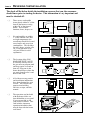
This unit must be installed by a qualified installer to prevent the possibility of
an explosion. Your dealer will know the requirements in your area and can
inform you of those people considered qualified. The room heater should be
inspected before use and at least annually by a qualified service person. More
frequent cleaning may be required due to excessive lint from carpeting,
bedding material, etc.
The instructions in this manual must be strictly adhered to. Do not use
makeshift methods or compromise in the installation. Improper installation
will void the warranty and safety listing.
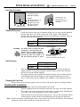
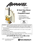
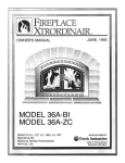
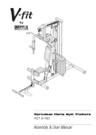
This stove may be converted to either natural gas (NG) or propane (LP).
Burning the incorrect fuel will void the warranty and safety listing and may
cause an extreme safety hazard. Direct questions about the type of fuel used to
your dealer. Check the label and flame adjust knob on the gas control valve.
VENT
¥
PI L OT
PAGE 2
HAS BEEN
CONVERTED FOR
NATURAL GAS
LP
PILOT ADJ
N atural G as
LP (Propane)
¥
Ok
¥
¥
Gas
¥
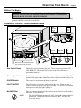
Contact your local
building officials to
obtain a permit and
information on any
installation restrictions or
inspection requirements in
your area. Notify your
insurance company of this
heater as well.
It is imperative that
control compartments,
screens, or circulating air
passageways of the heater
be kept clean and free of
obstructions. These areas
provide the air necessary
for safe operation.
Do not store or use
gasoline or other
flammable liquids in the
vicinity of this heater.
Keep all furniture or other
combustible items at least
36" away from the front
of the stove.
¥
If the flame becomes
sooty, dark orange in
color, or extremely tall,
do not operate the heater.
Call your dealer and
arrange for proper
servicing.
¥
Do not operate the heater
if it is not operating
properly in any fashion or
if you are uncertain. Call
your dealer for a full
explanation of your heater
and what to expect.
¥
Do not operate if any
portion of the heater was
submerged in water or if
any corrosion occurs.
?
SAFETY PRECAUTIONS (CONTINUED)
¥
¥
¥
¥
¥
¥
¥
¥
¥
¥
Do not place clothing or
other flammable items on
or near the heater.
Because this heater can be
controlled by a thermostat
there is a possibility of the
heater turning on and
igniting any items placed
on or near it.
The viewing door should
be opened for service only
(see the maintenance
section of this manual).
Any safety screen or
guard removed for
servicing must be
replaced prior to
operating the room heater.
Operate the heater
according to the
instructions included in
this manual.
If the main burners do not
start correctly turn the gas
off at the gas control
valve and call your dealer
for service.
This unit is not for use
with solid fuel
Do not place anything
inside the firebox (except
the included fiber logs).
If the fiber logs become
damaged, replace with
Travis Industries log set.
Do not touch the hot
surfaces of the heater.
Educate all children of the
danger of a hightemperature heater.
Young children should be
supervised when they are
in the same room as the
heater.
Instruct everyone in the
house how to shut gas off
to the appliance and at the
gas main shutoff valve.
The gas main shutoff
valve is usually next to
the gas meter or propane
tank and requires a
wrench to shut off.
PAGE 3
¥
Light the heater using the
built-in piezo igniter. Do
not use matches or any
other external device to
light your heater.
¥
Never remove, replace,
modify or substitute any
part of the stove unless
instructions are given in
this manual. All other
work must be done by a
trained technician. Don't
modify or replace orifices.
Allow the stove to cool
before carrying out any
maintenance or cleaning.
¥
¥
The pilot flame must
contact the thermopile,
thermocouple and deflect
off the pilot hood when
turned on. If it does not,
turn the gas control valve
to "OFF" and call your
dealer.
¥
Do not throw this manual
away. This manual has
important operating and
maintenance instructions
that you will need at a
later time. Always follow
the instructions in this
manual.
¥
Plug the stove into a
115 V. grounded
electrical. Do not use an
adapter plug or remove
the grounding plug.
Don't route the electrical
cord in front of or over
the stove
This
Manual
¥
¥
Travis Industries, Inc.
grants no warranty,
implied or stated, for the
installation or
maintenance of your
heater, and assumes no
responsibility of any
consequential
damage(s).
PAGE 4
TABLE OF CONTENTS
General Information
Introduction & Important Information ................................................................................................... 1
Safety Precautions............................................................................................................................... 2
Features & Specifications .................................................................................................................... 5
Stove Installation
Heater Placement ................................................................................................................................ 6
Floor Protection ................................................................................................................................... 7
Vent Requirements .............................................................................................................................. 7
Gas Line Install .................................................................................................................................... 8
Finalizing the Installation ..................................................................................................................... 9
Insert Installation
Heater Placement ................................................................................................................................ 10
Fireplace Sizing ................................................................................................................................... 11
Floor Protection ................................................................................................................................... 11
Vent Requirements .............................................................................................................................. 11
Gas Line Install .................................................................................................................................... 12
Finalizing the Installation ..................................................................................................................... 13
Operating Your Heater
Reviewing the Installation .................................................................................................................... 14
Before You Begin................................................................................................................................. 15
Location of Controls ............................................................................................................................. 15
Starting The Pilot ................................................................................................................................. 16
Running Your Heater ........................................................................................................................... 17
Starting the Heater for the First Time ........................................................................................... 17
Turning the Heater On and Off ..................................................................................................... 18
Adjusting the Flame Height .......................................................................................................... 19
Adjusting the Blower Speed ......................................................................................................... 19
Normal Operating Sounds ................................................................................................................... 19
Maintaining Your Heater
Inspecting the Firebox ......................................................................................................................... 20
Installing the Logs and Coals............................................................................................................... 21
Inspecting the Door ............................................................................................................................. 22
Replacing the Door Gasket .......................................................................................................... 22
Replacing the Glass or Glass Gasket........................................................................................... 22
Troubleshooting
Troubleshooting Table ......................................................................................................................... 23
How this Heater Works ........................................................................................................................ 24
What Turns the Main Burners On and Off .................................................................................... 24
Why Nothing Should Be Placed Against the Heater..................................................................... 24
What Prevents Gas Buildup ......................................................................................................... 25
Wiring Diagram ............................................................................................................................. 26
Replacement Parts List ................................................................................................................ 26
Warranty
Warranty .............................................................................................................................................. 27
Listing Information
Listing Information ............................................................................................................................... 28
Optional Equipment
Legs ..................................................................................................................................................... 29
Pedestal ............................................................................................................................................... 29
Surround Panels .................................................................................................................................. 30
Telescoping Legs................................................................................................................................. 31
Remote Control ................................................................................................................................... 32
Thermostat........................................................................................................................................... 34
Re-Routing the Power Cord to the Left or Rear of the Heater............................................................. 36
Index
Index .................................................................................................................................................... 38
FEATURES AND SPECIFICATIONS
Installation Options:
Features:
¥
¥ Freestanding
¥
¥ Freestanding in an Alcove
¥
¥
¥
¥
¥
¥ Masonry Fireplace Insert
¥ Factory-Built (Z.C.) Fireplace
Insert
¥
Works During Power Outages
(utilizes millivolt system)
High Efficiency; Up to 80% for Natural
Gas, 82% for LP (Steady State)
Optional Thermostat or Remote Control
Realistic "Wood Fire" Look
Convenient Operating Controls
Variable-Rate Heat Output
Quiet Blower for Effective Heat
Distribution
Low Maintenance
Heating Specifications:
Approximate Maximum Heating Capacity (in square feet)*
High Burn Input Rate (In BTU's)**
Low Burn Input Rate (In BTU's)**
AFUE Efficiency
*
**
PAGE 5
700 Natural
Gas
600 - 1600
31,000
18,000
70.0 %
700 LP
(propane)
600 - 1600
31,000
17,000
70.0 %
Heating capacity will vary depending on the home's floor plan, degree of insulation, and the outside temperature. It is also
affected by the natural gas or LP BTU rating.
To measure the net BTU's, multiply the BTU input by the efficiency percentage (80% for natural gas, 82% for LP).
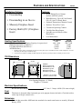
700 Dimensions
18 1/2"
23 5/8"
HEIGHT*:
Without Legs 20 1/8"
With Pedestal 31 3/8"
With Brass Legs 28"
With Cast Legs 28"
With Black Legs 26 5/8"
3 1/4"
* Subtract 1 1/8" to reach
the base of the flue collar
Vent Opening Diameter = 4" (Both)
Weight = 175 Pounds
Electrical Specifications:
Blower Electrical Rating:
115 Volts, 1.3 Amps, 60 Hz (150 watts on high)
Fuel:
The heater is designed either for natural gas or for propane (but not for both). Check the sticker
on the top of the gas control valve.
Emissions:
This unit has passed the ANSI emission standards for vented room heaters as tested by Warnock
Hersey, LTD.
PAGE 6
STOVE INSTALLATION -
For qualified installers only!
This appliance must be installed in accordance with all local codes, if any; if not,
follow ANSI Z223.1 and the requirements listed in this manual. Failure to follow all
of the requirements may result in property damage, bodily injury, or even death.
Check with local building officials for any permits required for installation of this gas heater and
notify your insurance company before hooking up this heater. The requirements listed below are
divided into sections. All requirements must be met simultaneously. The order of installation is
not rigid Ð the qualified installer should follow the procedure best suited for the installation.
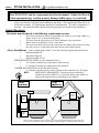
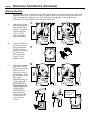
Heater Placement
The heater must be placed so the following requirements are met:
¥
Stove must be placed so that no combustibles are within, or can swing within (e.g.
drapes, doors), 36" of the front of the heater
¥
The stove must be placed on a set of Travis Industries legs or pedestal
¥
Heater must be installed on a level, secure floor
¥
The stove must not be placed so the vents below the ashlip, above the door, along
the sides of stove, or along the back of the heater can become blocked
Alcove Installations If the ceiling height is under 7 feet, the following requirements must be met:
¥
Minimum height 58"
¥
Maximum depth 48"
¥
Minimum width 43-5/8"
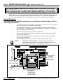
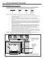
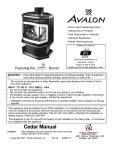
STRAIGHT INSTALLATION (see the illustration below)
¥
10" clearance from the top of the heater to the sidewall
¥
3" clearance from the top of the heater to the backwall
CORNER INSTALLATION (see the illustration below)
¥
4" clearance from the rear top corner of heater to the cornerwall (at a 45° angle)
HINT:
REDUCING CLEARANCES - Clearances may be reduced by
methods specified in NFPA 211, listed wall shields, pipe shields, or
other means approved by local building or fire officials.
Corner
Installation
Sidewall
3" MIn.
(to top of
stove)
l
al
rw
ne
or
C
Backwall
C
or
ne
rw
al
l
Straight
Installation
4" MIn.
(to top of
stove)
10" MIn.
(to top of
stove)
When the stove is installed directly on carpeting, vinyl, or other combustible material other than wood flooring,
the stove must be installed on a metal or wood protection panel extending the full width and depth of the stove.
STOVE INSTALLATION (CONT.) -
For qualified installers only!
PAGE 7
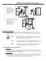
Floor Protection
When the stove is installed directly on carpeting, vinyl or other combustible material other than
wood flooring, the stove must be installed on a metal or wood protection panel extending the full
width and depth of the stove.
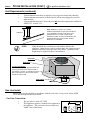
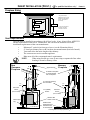
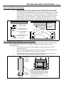
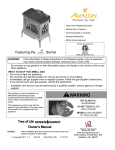
Vent Requirements
The vent must be installed in accordance with all local codes, if any; if not, follow ANSI 223.1
and the requirements listed below. Furthermore, the vent must be installed to meet the
installation requirements of the vent manufacturer.
¥
Minimum 5' vertical rise from top of stove (see the illustration below)
¥
The horizontal run may not exceed 50% of the vertical rise
¥
Use 4" dia. B vent for entire system from one manufacturer (don't mix brands)
- or Use high temperature factory built chimney and connector with listed gas
chimney liner running the entire length
¥
The vent must not service another appliance
¥
1" clearance to all combustibles must be maintained
¥
Must meet all of the vent manufacturer's requirements
¥
Vent termination must be above the roof and not below any eaves or overhangs
Do not block gas
vent termination
Vent must
terminate a
minimum 1'
above the roof.
Maintain 1"
minimum
clearance
Min. 5' Rise
Min. 5' Rise
High
temperature
factory built
chimney and
connector
Provide a 1/4" rise
for every 12" run.
Type B Vent
The total
horizontal
run must
not exceed
50% of the
vertical rise
Standard Installation
Exterior Vent
Listed Gas
Chimney Liner
Chimney with Liner
PAGE 8
STOVE INSTALLATION (CONT.) -
For qualified installers only!
Vent Requirements (continued)
¥
¥
Vent termination must have an approved cap (to prevent water from entering)
Vent termination must not be located where it will become plugged by snow or
other material
Vent termination must be 1' above the roof and meet the requirements outlined in
ANSI 223.1, section 7.6.2.
¥
Note: ANSI 223.1, section 7.6.2 outlines
additional requirements for gas vent terminations.
If your installation involves a roof with a slope
greater than 6/12 or if a wall or other verical
obstruction is within 8' of the vent termination, the
vent termination will need to be taller. Refer to
ANSI 223.1 for full details.
1' Minimum
NOTE:
When installed, the vent must provide suitable draft for the
appliance. Other factors, such as exhaust fans, may create negative
pressure inside the home and cause down drafts. Additional vent
height may be required in these circumstances.
Vent Collar
Draft Hood
TO TEST THE DRAFT:
Remove the back panel. Start the heater and
check the perimeter of the draft hood with a
gas detector or smoke. If combustion products
leak out the draft hood, the vent may need to
be taller to improve draft.
Spill Switch
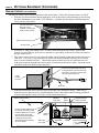
Gas Line Install
The gas line must be installed in accordance with all local codes, if any; if not, follow ANSI
223.1 and the requirements listed below.
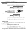
Gas Line Connection:
¥
¥
The gas inlet is a male 3/8" NPT
This appliance requires a shutoff valve upstream of
the appliance. This valve must be accessible and
within 3 feet of the heater.
STOVE INSTALLATION (CONT.) -
For qualified installers only!
PAGE 9
Gas Inlet Location:
LOCATION OF THE
GAS INLET CENTER:
CL
7 1/2" (from
center of stove)
HEIGHT:
From Base of Stove 1 1/2"
With Pedestal 12 3/4"
With Brass Legs 9 3/8"
With Cast Legs 9 3/8"
With Black Legs 8"
The 3/8" N.P.T. gas
inlet portrudes 1 1/2"
from the back edge of
the stove.
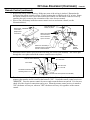
Manifold Pressure:
¥
Check the pressure of the gas downstream of the valve by removing the manifold
pressure tap with a 3/16" allen wrench (1/8" N.P.T. plug). If the manifold
pressure does not match the pressure listed in the table below, check the inlet gas
pressure and correct the problem.
Manifold Pressure with Regulator on HI
Natural Gas
3.5" W.C.
Propane
11" W.C.
HI-LO Regulator
WARNING: The heater must be turned off while
connecting or disconnecting the
pressure tap or pressure sensing
device. Gas will ignite through the
pressure tap hole if the heater is on
and the pressure tap hole is open!
Manifold Pressure Tap
(1/8" N.P.T. fitting)
Use a 3/16" allen wrench to remove.
Gas Pressure:
¥
¥
Minimum Input Pressure
Natural Gas
7" W.C.
Propane
11" W.C.
If the pressure is not sufficient, make sure the piping used is large enough, the
supply regulator is adequately adjusted, and the total gas load for the residence
does not exceed the amount supplied.
The supply regulator (the regulator that attaches directly to the residence inlet or
to the propane tank) should supply gas at the suggested input pressure listed
above. Contact the local gas supplier if the regulator is at an improper pressure.
Purging the Gas Line:
The gas line must be properly purged to release all air in the gas line prior to starting the heater.
Finalizing the Installation
¥
¥
¥
Before starting, all gas line joints must be leak tested.
Optional equipment must be installed (instructions are in the rear of this manual).
The ceramic logs must be placed inside the firebox (see the section "Installing the
Logs and Coals" in the maintenance section of this manual).
¥
Start the heater and check for proper performance. Review the operations portion
of this manual to make sure the owner understands the operation of the heater.
Note: See the instructions "Re-Routing the Power Cord to the Left or Rear of the Heater" in the optional
equipment section of this manual to re-route the power cord.
PAGE 10
INSERT INSTALLATION -
For qualified installers only!
This appliance must be installed in accordance with all local codes, if any; if not,
follow ANSI Z223.1 and the requirements listed in this manual. Failure to follow all
of the requirements may result in property damage, bodily injury, or even death.
Check with local building officials for any permits required for installation of this gas heater and
notify your insurance company before hooking up this heater. The requirements listed below are
divided into sections. All requirements must be met simultaneously. The order of installation is
not rigid Ð the qualified installer should follow the procedure best suited for the installation.
Heater Placement
The heater may be installed in a masonry or zero-clearance (metal) fireplace with the
following requirements:
¥
¥
¥
¥
¥
¥
The insert must be placed so that no combustibles are within, or can swing within
(e.g. drapes, doors), 36" of the front of the heater
The insert must be installed in a level, undamaged masonry or zero-clearance
(metal) fireplace. Any damage must be repaired prior to installation. The heater
must not extend beyond the hearth.
The insert must maintain a 10" clearance to sidewalls
The non-combustible side facing (e.g. brick, tile, cement board) must extend 8"
from the side of the insert
The non-combustible top facing (e.g. brick, tile, cement board) must extend 8"
above the top of the insert
The combustible mantle must be at least 17" above the top of the insert
HINT:
REDUCING CLEARANCES - Clearances may be reduced by
methods specified in NFPA 211, listed wall shields, pipe shields, or
other means approved by local building or fire officials.
Combustible Mantle
Sidewall
17" Min.
8" Min.
10" Min.
8" Min.
Floor protection must
extend underneath
insert to the faceplate
HEIGHT INCLUDING
TOP PANEL:
28" with 8" Panels
30" with 10" Panels
32" with 12" Panels
23 5/8" Min.
(Width of Floor Protection)
WIDTH INCLUDING
SIDE PANELS:
40" with 8" Panels
44" with 10" Panels
48" with 12" Panels
Floor Protection
The heater must be installed over a non-combustible 3/8" thick hearth that
extends to both sides and from the rear edge of the heater to the front edge.
INSERT INSTALLATION (CONT.) -
For qualified installers only!
PAGE 11
Fireplace Sizing
* The gas inlet may be
located at the rear or on the
left side if the Side Inlet Kit
is used. Allow space for
gas hookup.
24" Minimum
21" Minimum**
21" Minimum
* * The extra space above
the heater is to allow
connection of the flue.
13" Minimum*
5 3/4" Minimum
24" Minimum*
Vent Requirements
The vent must be installed in accordance with all local codes, if any; if not, follow ANSI 223.1
and the requirements listed below. Furthermore, the vent must be installed to meet the
installation requirements of the vent manufacturer.
¥
Minimum 5' vertical rise from top of stove (see the illustration below)
¥
4" listed gas chimney liner or B vent from one manufacturer (don't mix brands)
¥
Vent must reline the entire length of the chimney
¥
The vent must not service another appliance
¥
Must meet all of the vent manufacturer's requirements
NOTE:
When using flexible gas vent, do not crimp or rupture the liner when
bending it around a chimney offset
Zero
Clearance
Fireplace
6"
Min.
Approved Cap
Masonry
Fireplace
A sealed cover plate
is recommended,
but not required.
17"
Min.
Surround
Panel
(Do not seal)
Telescoping
Leg
4" Listed gas chimney
liner or B Vent
Z.C. (Metal)
firebox
17"
Min.
Surround
Panel
(Do not seal)
Gas line with
shutoff valve
Hearth and/or
hearth pad must
extend at least
to the faceplate
Leveling bolts for step-up hearths
6"
Min.
PAGE 12
INSERT INSTALLATION (CONT.) -
For qualified installers only!
Vent Requirements (continued)
The vent termination must meet the following requirements:
¥
¥
Vent termination must have an approved cap (to prevent water from entering)
Vent termination must not be located where it will become plugged by snow or
other material
Vent termination must extend a minimum of 6" above the top of the chimney
NOTE:
When installed, the vent must provide suitable draft for the
appliance. Other factors, such as exhaust fans, may create negative
pressure inside the home and cause down drafts. Additional vent
height may be required in these circumstances.
¥
How to tell if you have negative pressure:
The most common indication of a negative pressure situation is the heater (and pilot) turning off
between 10 and 25 minutes from the time the main burner was started (this happens most often on
cold days). The main burner turns on, but instead of warming the flue and creating draft, it vents out
of the draft hood at the rear of the heater. The spill switch then heats up, and in about 5 to 15
minutes shuts off all gas to the heater (shutting off the main burner and pilot). If a thermostat is used
on your heater, and the pilot shuts down sporadically, you may have a negative pressure situation.
Gas Line Install
The gas line must be installed in accordance with all local codes, if any; if not, follow ANSI
223.1 and the requirements listed below.
Gas Line Connection:
¥
¥
The gas inlet is a male 3/8" NPT
This appliance requires a shutoff valve upstream of
the appliance. This valve must be accessible and
within 3 feet of the heater.
Gas Inlet Location:
LOCATION OF THE
GAS INLET CENTER:
The 3/8" N.P.T.
gas inlet
portrudes 1
1/2" from the
back edge of
the stove.
CL
7 1/2" (from
center of stove)
LOCATION OF THE GAS INLET
CENTER WITH THE SIDE INLET KIT:
1 1/2" Above
the base of
the stove
1 1/2"
Above the
base of
the stove
2 1/8" Behind the
fireplace opening
The 3/8" N.P.T.
gas inlet
portrudes 1
1/2" from the
back edge of
the stove.
INSERT INSTALLATION (CONT.) -
For qualified installers only!
PAGE 13
Manifold Pressure:
¥
Check the pressure of the gas downstream of the valve by removing the manifold
pressure tap with a 3/16" allen wrench (1/8" N.P.T. plug). If the manifold
pressure does not match the pressure listed in the table below, check the inlet gas
pressure and correct the problem.
Manifold Pressure with Regulator on HI
Natural Gas
3.5" W.C.
Propane
11" W.C.
HI-LO Regulator
WARNING: The heater must be turned off while
connecting or disconnecting the
pressure tap or pressure sensing
device. Gas will ignite through the
pressure tap hole if the heater is on
and the pressure tap hole is open!
Manifold Pressure Tap
(1/8" N.P.T. fitting)
Use a 3/16" allen wrench to remove.
Gas Pressure:
¥
¥
Minimum Input Pressure
Natural Gas
5.5" W.C.
Propane
11" W.C.
If the pressure is not sufficient, make sure the piping used is large enough, the
supply regulator is adequately adjusted, and the total gas load for the residence
does not exceed the amount supplied.
The supply regulator (the regulator that attaches directly to the residence inlet or
to the propane tank) should supply gas at the suggested input pressure listed
above. Contact the local gas supplier if the regulator is at an improper pressure.
Purging the Gas Line:
The gas line must be properly purged to release all air in the gas line prior to starting the heater.
Finalizing the Installation
¥
¥
¥
Before starting, all gas line joints must be leak tested.
Optional equipment must be installed (instructions are in the rear of this manual).
The ceramic logs must be placed inside the firebox (see the section "Installing the
Logs and Coals" in the maintenance section of this manual).
¥
Start the heater and check for proper performance. Review the operations portion
of this manual to make sure the owner understands the operation of the heater.
Note: See the instructions "Re-Routing the Power Cord to the Left or Rear of the Heater" in the optional
equipment section of this manual to re-route the power cord.
PAGE 14
REVIEWING THE INSTALLATION
The check off list below details the installation concerns that you, the consumer,
should know prior to starting the heater. This information is very important and
must be checked off.
( )
( )
There are no combustible
items placed within 36" of the
front of the heater or swing
within 36" of the front of
heater. This includes
furniture, doors, drapes, etc.
No combustibles are within
1" of the exhaust vent. Due
too high temperatures, the
room heater should be located
out of traffic and away from
combustibles. This includes
drywall, drapes, window sills,
etc. If any question exists,
call your dealer for a full
explanation.
( )
The location of the GAS
MAIN SHUTOFF VALVE.
It is usually directly next to
the gas meter or propane tank
and may require a wrench to
shut off. Everyone in the
house should know where the
gas main shutoff valve is and
how to turn it off.
( )
All of the necessary permits
and installation information
have been obtained for your
records. This includes the
permits from building
officials, receipts, and this
manual.
( )
The operation card included
with the heater slides out
from behind the access panel.
If you can not find it, call
your dealer for details. This
card includes important
operation information that
must be kept with the heater
at all times.
36" Minimum
Combustible
Gas Vent
Combustible
Min.1"
clearance
On most valves this is ON
On most valves this is OFF
OWNER'S
MANUAL
Ok
Permits
Receipts
This Manual
OPERATING YOUR HEATER
PAGE 15
Before You Begin
READ THIS ENTIRE MANUAL BEFORE YOU USE YOUR NEW HEATER.
FAILURE TO FOLLOW THE INSTRUCTIONS MAY RESULT IN PROPERTY
DAMAGE, BODILY INJURY, OR EVEN DEATH.
Before starting your heater make sure you have read the section titled Safety Precautions. Any
questions should be referred to your dealer.
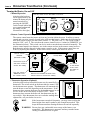
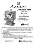
Location of Controls - See explanation below
Gas
Control
Knob
With the access panel flipped down
the controls can be accessed.
ON
PILOT
IGNITER
PILOT
IGNITER
BLOWER
Dial
OFF H I
LO
BLOWER
MAIN BURNER
ON/OFF
Switch
Flame
Adjust
Knob
OFF
Gas Control Knob
This knob is used for starting the pilot. There are three positions, ON,
OFF, & PILOT. The pointer directly below the knob indicates the
position this knob is in.
Flame Adjust Knob
This knob controls the flame height from low ("LO") to high ("HI"). The
pointer to the upper right of the knob points to the position this knob is in.
ON/OFF Switch
This control is used to turn the heater on and off.
PILOT IGNITER
The pilot igniter is used only while starting the pilot. When pressed, it
sends an electrical charge to the pilot assembly. This creates a blue spark
directly next to the pilot light, igniting it.
BLOWER Dial
This dial controls the speed of the internal convection blower that pushes
the heated air into the room.
NOTE:
The ON/OFF Switch must be left "ON" if using the remote control or
thermostat. Turning the ON/OFF Switch to "OFF" will keep the
heater off always.
PAGE 16
OPERATING YOUR HEATER (CONTINUED)
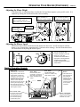
Starting The Pilot
OFF
OFF
P
IN
I L
OT
OT
Wait five minutes to
let any gas that may
have accumulated
inside the firebox
escape. If you smell
gas, follow the
directions on the
cover "IF YOU
SMELL GAS".
P
I L
B.
A
ON
Push the gas control
knob in slightly and
turn it to the "OFF"
position. The knob
will not turn from
"ON" to "OFF"
unless the knob is
depressed slightly.
IN
A.
ON
The pilot light is used to ignite the main burners when the stove is turned on and also provides an
important safety role. It will stay lit once it is started. However, the gas flowing to the pilot will
shut off whenever the pilot goes out. If the pilot turns off frequently, call your dealer for
information. To start the pilot follow the directions below:
B
C
OF
F
P
I L OT
ON
OF
F
IN
P
I L OT
IN
Turn the gas control
knob to the "PILOT"
position and press the
knob in, this will
allow gas to flow to
the pilot light. Press
the red button on the
pilot igniter
repeatedly until you
see the pilot light.
KEEP THE GAS
CONTROL KNOB
DEPRESSED FOR
30 SECONDS
ONCE IT IS LIT.
Note: If the pilot
does not light after
several tries, call
your dealer for
service.
ON
C.
Keep the knob
pressed in for
30 seconds
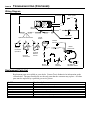
OPERATING YOUR HEATER (CONTINUED)
PAGE 17
D
If the pilot
light goes
out after
releasing
the knob,
repeat step
C above.
OF
F
I L OT
OFF
P
P
I L
E
OT
ON
IN
Turn the gas control
knob counterclockwise to "ON".
The pilot is now lit
and the heater can be
turned on and off.
IN
E.
Release the gas
control knob. If the
pilot goes out, repeat
step C. If the pilot
refuses to stay lit,
call your dealer for
service.
ON
D.
Running Your Heater
Your heater may be turned on and off manually, with the optional remote control, or by the
optional thermostat. The speed of the blower and the height of the flame can also be adjusted
manually.
NOTE:
When the heater first comes on, the flames will be blue and
somewhat transparent. After fifteen minutes the flames will turn a
more realistic yellow and orange color.
NOTE:
Certain installations use a remote "wall switch" to turn the heater on
and off. If this is the case, leave the ON/OFF switch on "ON".
NOTE:
When this switch is turned to the "OFF" position the main burner
will not operate. However, the pilot flame will stay lit.
Starting the Heater for the First Time
Cure the Paint
To cure the paint, start the heater and turn the flame height to low. Leave it on for 20 minutes
then turn it off and let it cool. Repeat this process two more times to fully cure the paint. You
will smell the paint curing Ð this is normal.
Ventilate the Room
You may wish to ventilate the room by opening a window. Furthermore, the glass may become
obscure during the first 10 hours of burning due to the components inside the firebox curing.
Clean the glass with a glass cleaner after the first ten hours of operation.
PAGE 18
OPERATING YOUR HEATER (CONTINUED)
Turning the Heater On and Off
ON
PILOT
IGNITER
OFF H I
LO
BLOWER
Use this switch to turn the heater on and off.
MAIN BURNER
¥ Manual Operation
After the pilot has been
on for approximately one
minute the heater may be
turned on and off by
pressing the ON/OFF
switch located behind the
access panel underneath
the ashlip (see the
illustration to the right).
OFF
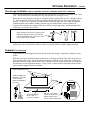
¥ Remote Control Operation (Optional)
The remote control turns the heater on from any location within the room. It utilizes a remote
control and a receiver (usually located in the wall near the heater). Make sure the following has
been done before trying to use the remote control: 1) The pilot is on; 2) The on/off switch is
turned to "ON", and; 3) The switch on the remote control receiver is turned to "REMOTE" (see
the illustration below). This switch can also be used to turn the heater on and off manually. The
remote control requires two batteries, one in the remote and one in the remote control receiver .
Both batteries must be charged for the remote control to work. If the remote control does not
work, try replacing the batteries. If this doesn't work, contact your dealer for service.
Remote Control
Receiver
(Mounted to Wall)
Remove the upper
and lower screws to
access the battery
Turn this switch to
"REMOTE" to use
the remote control
Remote Control
Hookup Wire
FIRELYTER
REMOTE OFF ON
This button
on the remote
control turns
the heater on
and off
Remove the screw on the back of the
remote control to access the battery
¥ Thermostat Operation (Optional)
After the pilot has been started the heater may be controlled by a
thermostat. The on/off switch on the heater must be turned "ON"
for the thermostat to operate. The thermostat will automatically
turn the heater on and off depending on the temperature. If the
thermostat does not turn the heater on, the thermostat may be set
too low or the on/off switch may be turned "OFF". If the
thermostat does not turn the heater off, the thermostat may be
set too high. If the thermostat does not work after making these
adjustments, call your dealer for service.
HINT:
If the heater turns on and off frequently, you may want to adjust the
flame height down until it produces just enough heat needed. This
keeps the thermostat from turning the heater on and off repeatedly.
WARNING: Do not place any combustible items on top of the heater, even
temporarily. The thermostat is automatic and may start the heater
causing a combustible item to ignite.
OPERATING YOUR HEATER (CONTINUED)
PAGE 19
Adjusting the Flame Height
Your heater has an adjustable flame to tailor the look and heat output to your specific needs. It is
adjusted by turning the middle dial on the valve assembly.
Turn clockwise to
adjust the flame higher.
The flame height adjustment
knob is located under the
ashlip behind the access panel
I
H
LO
I
LO
Index Mark
H
Flame Height
Adjustment Knob
Turn counter-clockwise
to adjust the flame lower.
Adjusting the Blower Speed
ON
OFF H I
LO
OFF
BLOWER
MAIN BURNER
The blower helps transfer the heat from the heater into the room. It will not turn on until the
heater is up to temperature (approximately 10 minutes after starting). See the illustration below
for instructions on adjusting the blower speed.
Turn the knob all the way
counter-clockwise to turn the
blower off. One click
clockwise turns the blower to
high speed. Turning the knob
clockwise from the high
position decreases the speed
of the blower.
Normal Operating Sounds
Burner Pan
The burner pan is underneath
the logs and is used to mix the
proper amount of air with the
natural gas to produce a clean
and efficient burn. When it is
started you will hear a slight
"whoosh" sound. When the
main burner is running you will
hear the gas flowing through
the burner pan and orifices Ð
this sound will decrease as the
flame height is lowered.
Gas Control Valve
As the gas control valve is
turned on and off you will
hear a dull clicking sound.
This is the valve opening
up and shutting down.
Stove Body
Due to the heavy steel
construction, occasional
clicks may come from the
heater, especially during
startup.
Pilot Flame
The pilot flame, which
remains on, makes a very
slight "whisper" sound.
Blower
This heater uses a
high tech blower to
push heated air
into the room. It
will make a whirring
sound and will
increase in volume
as the speed is
increased.
Blower Thermodisk
This part can produce a
clicking sound as it turns
the blower on and off.
PAGE 20
MAINTAINING YOUR HEATER
Every year you should inspect the firebox and door to make sure they are clean and functional.
WARNING: Failure to inspect and maintain your heater may lead to improper
burning inside the heater, leading to a dangerous situation.
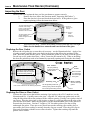
Inspecting the Firebox
The firebox should be inspected and cleaned of any soot or dust that may have been drawn into
the heater. To do this, follow the directions below.
1.
Remove the door (see the illustration below).
1.
Unscrew the handle
until it can be removed.
2.
Swing the
door open.
4.
3.
Lift the
door off
the hinges
(use both
hands).
2.
3.
When replacing the
handle make sure
the handle is facing
outwards, otherwise
it may burn.
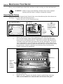
Remove the logs and coals (see the instructions on the following page).
Use a vacuum cleaner with a soft brush attachment to vacuum any dirt off the
burner pan (see the illustration below). The rear log is fragile and should not be
vacuumed. Inspect the burner pan and firebox for any deterioration. If it shows
signs of deterioration, call your dealer for a full inspection. There should be no
soot in the firebox, except for a small amount on the logs where the flames brush
up against them. If there is additional soot, the heater may need adjustment.
Contact your dealer for information.
Rear log
Make sure
all the
burner
holes are
clean and
no dirt has
collected
4.
5.
Log clips
To replace the front log and coals follow the directions in the section "Installing
the Logs and Coals".
Replace the door. Turn the door handle clockwise until the door seals tight.
Make sure the handle faces outwards and is not in front of the glass.
MAINTAINING YOUR HEATER (CONTINUED)
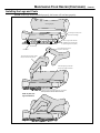
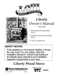
Installing the Logs and Coals
NOTE: If the logs are not installed properly, the heater will not burn properly.
Rear Log (largest)
The rear log has a flat portion
that rests on this ledge
Front Log
AA
AA
Pilot Assembly
Burner Pan
The left twig has two holes to accept
the pins in the front and rear log.
A
A
The front log has two slots that
straddle the clips on both sides
(push the log all the way back).
The right twig has a hole for
the pin on the left twig.
Right Twig
Left Twig
AA
Place the right twig so the lower
branch rests inside this channel.
Place the coals on this ledge at the front of the firebox .
Do not place the coals over the burner holes.
When in place, the
logs look like this.
PAGE 21
PAGE 22
MAINTAINING YOUR HEATER (CONTINUED)
Inspecting the Door
The door must seal against the door seal for your heater to operate correctly.
1.
Remove the door (follow the directions under "Inspecting the Firebox").
2.
Place the door face down and check the items below. If the gaskets or glass
require replacing, follow the instructions below.
The door gasket should be
unbroken, have enough
bulge to contact the face of
the unit, and be firmly
attached to the door frame.
Check the
glass for any
cracking.
The door
handle
slides out
of this hole.
The glass gasket should
form an airtight seal
between the glass and the
door frame.
3.
Then replace the door. Turn the door handle clockwise until the door seals tight.
Make sure the handle faces outwards and is not in front of the glass.
Replacing the Door Gasket
Remove the old gasket (use a screwdriver if necessary - see the illustration below). Apply a line
of gasket cement (available from your dealer) in the groove that follows the perimeter of the
door. Insert the gasket into the groove. Do not stretch the gasket as you place it into the groove.
Cut off any excess gasket when done. Allow 2 hours for the cement to dry. When re-installing
the door, the gasket may need to be flattened by repeatedly opening and closing the door firmly.
Cross Section
The glass is held in place with
the retainer clips and a 5" piece
of 3/8" flat white gasketing.
Door Gasket 7/8" rope gasketing
is held in place with
gasket cement.
Retaining Clip
Use a 5/16" nutdriver for the retaining clip screws.
3/8" flat gasketing behind the
retaining clips (prevents the glass
from cracking when being secured.
Door
Frame
Make sure there
is a small space
around the edge
of the glass
Glass Gasket 3/8" dia. white rope
gasket
Glass
Replacing the Glass or Glass Gasket
Unscrew the eight screws that hold the retaining clips in place with a 5/16" nutdriver (see the
illustration above). Carefully remove the glass. Align the 3/8" white rope gasket (new or old)
along the ledge that follows the perimeter of the window opening. If using a new gasket, trim off
any excess. Place the glass (new or old) in place so there is a small gap between the edge of the
glass and the door frame. Make sure the gasket is tucked underneath the glass so the glass does
not touch the door frame. Cut four 5" lengths of 3/8" flat white gasket or use the existing
undamaged flat gasket. These pieces are placed between the retaining clips and the glass to
prevent the glass from cracking or moving when the clips are secured. Place the glass clips in
place and secure them with the screws removed earlier. Tighten the retaining clips until the
gaskets start to flatten.
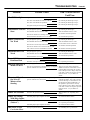
TROUBLESHOOTING
Problem:
Pilot Will Not Light
Possible Cause:
PAGE 23
Don't Call for Service
Until You:
A gas shut off valve is turned off
Check all gas shut off valves
The valve control knob isn't turned to "PILOT"
See "Starting the Pilot Light" Step C
The valve control knob isn't pushed in
See "Starting the Pilot Light" Step C
The igniter wasn't pressed repeatedly
See "Starting the Pilot Light" Step C
The pilot light has gone out
See "Starting the Pilot Light"
The ON/OFF switch is turned to "OFF"
Turn the ON/OFF switch to "ON"
The remote control is not working correctly
See "Remote Control Operation"
The thermostat is disconnected or set too high
See "Thermostat Operation"
The pilot light has gone out
See "Starting the Pilot Light"
The ON/OFF switch is turned to "OFF"
Turn the ON/OFF switch to "ON"
The remote is too far away from the heater
Use the remote closer to the heater
The remote control receiver is turned "Off" or "On"
See "Remote Control Operation"
One of the two remote control batteries is dead
See "Remote Control Operation"
The pilot light has gone out
See "Starting the Pilot Light"
The ON/OFF switch is turned to "OFF"
Turn the ON/OFF switch to "ON"
The thermostat is set too high
See "Thermostat Operation"
Heater Will Not
Distribute Heat
The heater is unplugged
Plug the heater in.
The heater is not up to temperature
See "Operating Your Heater"
Pilot Goes Out Once A
Month Or More
The gas supply has not been shut off
Keep the gas supply turned on
Flame (and Pilot) Goes
Out 10 to 25
Minutes After
Starting
The vent is experiencing a cold air blockage or a negative This is a necessary safety feature. First try
pressure situation exists in the home
restarting the heater. If it works correctly,
a cold air blockage occurred and the vent
just needed to be heated sufficiently. If
this problem is persistent the vent may
need to be improved or changes may need
to be done to remove the negative pressure
inside the home - see your dealer for
details
Flames Are Too Blue
The heater has just been started
This is normal - see "Operating Your
Heater"
Flames Are Orange
With Dirty Smoke
Flames Are Too Short
(Under 6")
Something may be placed against the heater
See "How this Heater Works"
The flame height may be turned too low
Turn the flame height to "HI" See "Operating Your Heater"
Something may be placed against the heater
See "How this Heater Works"
The logs are placed incorrectly
See "Installing the Logs and Coals"
Main Burners Will Not
Start
Remote Control Does
Not Work
Thermostat Does Not
Work
Thin Layer of Soot
Covers the Glass
The vent is experiencing a cold air blockage or a negative This is a necessary safety feature that
disables the heater if a down draft occurs.
pressure situation exists in the home
If this problem is persistent the vent may
need to be improved or changes may need
to be done to remove the negative pressure
inside the home - see your dealer for
details
PAGE 24
TROUBLESHOOTING (CONTINUED)
How this Heater Works
This gas heater is designed with safety as the primary concern. Most of the components inside
this heater are used for safety purposes. Therefore, only certified gas service technicians should
service this heater. Your dealer can help you find a certified gas service technician.
What Turns the Main Burners On and Off
This heater uses a "millivolt system" to control its operation. A millivolt is a very small
measurement of electricity. The thermopile, located directly next to the pilot light, generates
electricity when it is heated by the pilot light. If the pilot is not lit, the thermopile does not
generate electricity. This electricity is used to keep the gas valve open. Without it, the gas valve
shuts off all gas to the heater. That is why when starting the pilot the gas control knob has to be
pressed in long enough for the thermopile to heat up and start generating electricity. This current
not only keeps the gas valve open but also provides electricity for the ON/OFF switch, remote
control, or thermostat (see the illustration below). Because the thermopile generates the
electricity needed to turn the heater on and off, this heater can be operated when the power is out
(but the blower will not run).
When heated, the thermopile
generates electricity (a very small
amount, measured in "Millivolts").
This electricity is
needed to keep the
gas valve open
and to operate the
main burners.
The main burners
are switched on and
off using the
electricity generated
by the thermopile.
The ON/OFF switch,
remote control, or
thermostat control
the circuit to the
main burner.
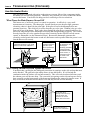
Why Nothing Should Be Placed Against the Heater
Your heater has a grill below the ashlip and convection air openings on the side and top that must
not be blocked. The grill below the ashlip allows air into the firebox. If it is blocked the
combustion inside the firebox will not burn normally. This will result in reduced efficiency and
the exhaust gases will become dirty. The convection air openings on the side and top are used to
draw room air over the hottest parts of the heater and distribute the warmed air into the room. If
they are blocked, the heater will not heat as well and may become too hot internally.
Do not block the air
openings on the side or top.
They are used to pull
convection air over the
hottest parts of the stove.
Do not block this grill. It
provides air for combustion.
TROUBLESHOOTING (CONTINUED)
PAGE 25
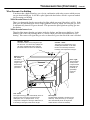
What Prevents Gas Buildup
Your heater has a high technology gas valve in combination with safety sensors which prevent
any gas from building up. It also has a pilot light inside the firebox, which is a proven method
for preventing gas buildup.
While the main burner is off
There is a thermopile directly next to the pilot light which can sense if the pilot is still lit. If the
pilot goes out, this thermopile will no longer generate electricity which will cause the gas valve
to automatically shut off all gas to the unit. This prevents the pilot light from spilling gas into
the firebox.
While the main burner is on
The pilot light insures that the gas ignites inside the firebox, and that no gas builds up. In the
unlikely case of the vent blocking, there is a sensor which will sense any backdrafts or overheating. This sensor will signal the gas valve to shut off all gas to the unit if the vent is blocked.
Spillage Sensor
This device detects if any flue gases spill
into the room. If it senses any spillage, the
gas valve automatically shuts off all gas
(the heater will then need to be restarted).
External Shut
Off Valve
This valve is
provided to shut
off gas to the
heater during
maintenance
procedures.
Gas Valve
This high technology valve automatically shuts off
all gas if it does not receive a signal from the
thermopile, door, or spillage sensor. If any
component is damged or sensing a malfunction, or
if the wiring is damaged, it will shut off all gas.
Ceramic Glass
The glass in your heater is the most
durable glass available. It has been
tested to be extremely resistant to
breakage and temperature changes.
Pilot Light
The pilot light is
a time-proven
component that
eliminates the
possibility of
gas buildup
inside the
firebox.
Thermopile
The thermopile generates a small amount of
electricity. If the pilot does go out, the gas
valve automatically shuts off all gas (the
heater will then need to be restarted).
PAGE 26
TROUBLESHOOTING (CONTINUED)
Wiring Diagram
Thermopile
Piezo Igniter
Orange
Green
Red
White
EPU
terminal
Red
Green
Red
Spill Switch
On/Off
Switch
Optional On/Off Devices
Red
Chassis
Ground
Blower
Motor
Black
Jumper
for Manual
Operation
Green
Molex
Connectors
White
Black
Optional
Thermostat
Optional
Remote
Control
Black
Black
White
Black
Black
Blower
Thermodisk
Blower
Rheostat
120 Volt A.C.
Grounded Outlet
Replacement Parts List
Replacement parts are available at your dealer. Contact Travis Industries for information on the
closest dealer. The parts listed below are the only parts that the consumer may replace. All other
parts must be replaced by a qualified gas service person.
PART
Part description
Door Gasket
Glass Gasket
Door Glass
Glass Clips
Handle for Door
Door Handle
Log Set (includes coals)
Owner's Manual
White 7/8" dia. Fiberglass rope 56" long
Black 3/8" dia. Fiberglass rope 62" long
5 mm neoceram, 10 1/8" tall @ center, 17.094" wide
Four clips used to hold glass in place, includes 4 self-adhesive fiberglass strips & 8 screws
Wood handle
Steel shaft with threaded end (includes wood handle)
Front and back log, left and right twig, and coals (ceramic fiber)
This document
WARRANTY
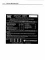
PAGE 27
TRAVIS INDUSTRIES, INC. warrants the AVALON 700 natural gas heater to be defect-free in material and workmanship for five (5)
years from the date of purchase, with the exception of the glass, paint, electrical components, switches, piezo igniter, fans, gaskets, logs,
moving parts, gas valve, manifold, and burner pan. This does not include service call cost or any other additional charges. Check with
your dealer for all costs if arranging a warranty call. The exceptions listed are warranted for one (1) year from the date of purchase to be
defect-free in material and workmanship, with the exception of the glass and paint, which are not covered by the warranty.
Exclusions to this limited warranty include: Injury malfunction to the product, loss, damage, defect, failure to function due to accident,
negligence, misuse, improper installation, alteration or adjustment of the manufacturers settings of components, lack of proper and regular
maintenance, damage incurred while the unit is in transit, alteration, or act of God.
This limited warranty excludes damage caused by normal wear and tear, such as paint discoloration or chipping, worn or torn gasketing,
eroded or cracked logs, coals, etc. Also excluded is damage to the unit caused by abuse, improper installation, modification of the unit,
drilling of the orifices, or the use of fuel other than natural gas.
TRAVIS INDUSTRIES, INC. is free of liability for any damages caused by the unit, as well as inconvenience expenses, material and labor
charges incurred by the removal or reinstallation of any AVALON 700 unit. Incidental or consequential damages are not covered by this
warranty. In some states, the exclusion of incidental or consequential damage may not apply.
This warranty does not cover any loss or damage incurred by the use or removal of any component or apparatus to or from the AVALON
700 unit without the express written permission of TRAVIS INDUSTRIES, INC. and bearing a TRAVIS INDUSTRIES, INC. label of
approval.
Any statement or representation of AVALON 700 products and their performance contained in AVALON 700 advertising, packaging
literature, or printed material is not part of this limited warranty.
This warranty is automatically voided if the unitÕs serial number has been removed or altered in any way.
Only the original purchaser of an Avalon 700 heater is covered by this warranty. If the unit is used for commercial purposes, it is excluded
from this warranty.
No dealer, distributor, or similar person has the authority to represent or warrant AVALON 700 products beyond the terms contained
within this warranty. TRAVIS INDUSTRIES, INC. assumes no liability for such warranties or representations.
THIS LIMITED WARRANTY IS THE ONLY WARRANTY SUPPLIED BY TRAVIS INDUSTRIES, INC., THE MANUFACTURER
OF THE UNITS. ALL OTHER WARRANTIES, WHETHER EXPRESS OR IMPLIED, ARE HEREBY EXPRESSLY DISCLAIMED
AND PURCHASERÕS RECOURSE IS EXPRESSLY LIMITED TO THE WARRANTIES SET FORTH HEREIN.
This warranty is limited to the time frame set forth above. In some states, time limitations on warranties do not apply.
HOW TO USE YOUR AVALON 700 FIVE-YEAR WARRANTY: If you find your unit to be defective in workmanship or material
within a 5-year period from the date of purchase contact your local authorized AVALON 700 dealer. If your dealer is unable to repair your
unitÕs defect, he may process a warranty claim through TRAVIS INDUSTRIES, INC., including the name of the dealership where you
purchased the unit, a copy of your receipt showing the date of the unitÕs purchase, and the serial number on your unit. At that time, you
will be asked to ship your unit, freight charges prepaid, to TRAVIS INDUSTRIES, INC. TRAVIS INDUSTRIES, INC., at its option, will
repair or replace, free of charge, your AVALON 700 unit if it is found to be defective in material or workmanship within the time frame
stated within this limited warranty. TRAVIS INDUSTRIES, INC. will ship your unit, freight charges prepaid by TRAVIS INDUSTRIES,
INC., to your regional distributor, or dealership.
To register your TRAVIS INDUSTRIES, INC. Five-Year Warranty, complete the enclosed warranty card and mail it within ten (10) days
of the unit purchase date to: TRAVIS INDUSTRIES, INC., 10850 117th Place N.E., Kirkland, Washington 98033.
OTHER RIGHTS:
This warranty provides you with certain legal rights. You may have additional rights, which vary from state to state, in regards to this
warranty.
Unit Serial Number
Date of Purchase
Complete and
Dealer Name and Address
save for your
records
Travis Industries, Inc. reserves the right to change, without notice, product features or specifications described.
10850 117th Place N.E. Kirkland, WA 98033
OPTIONAL EQUIPMENT
PAGE 29
Stove Legs Installation (Brass # 99200500, Cast Black # 99200800, Black Steel # 99200100)
There are three different stove legs available for your gas stove: cast brass; cast black; and, black
steel. The instructions for installing the legs are the same for each type of leg.
Raise the stove by inserting some pieces of lumber in the middle of the stove to a height of about
8". Line up the hole in the top of the leg with the threaded bolt hole in each corner of the stove
bottom. Using a 9/16" open end or socket wrench, fasten the leg to the stove with the supplied
attachment bolts and washers, making sure the legs are flush with the corners of the stove.
Unscrew the leveling bolts enough so the stove will rest on the upper tips, not the metal portion
of the legs. Lower the stove down.
Attach each leg to the stove by inserting a bolt
and washer through the hole or slot in the leg
and into the threaded hole on the stove. Use a
9/16" socket wrench to tighten.
To level the stove, lift the stove up and unscrew each leveling bolt the appropriate amount. The
rubber tips of the leveling bolts will tear if they are adjusted while weight is applied to them.
Pedestal (Part # 99200109)
Unpack the box containing the pedestal and check for any damage. Report any damage to your
dealer.
Slide the wood trim included with the pedestal on to the front and back edge of the pedestal so it
lines up from side to side. Place the pedestal in place and lift the stove on top of it. Line up the
threaded bolt holes in the bottom of the stove with the two holes on the tabs on the inside edge of
the pedestal (see the illustration below). Using a 9/16" socket wrench, fasten the pedestal to the
stove with the supplied bolts and washers.
Holes for attachment bolts
Attachment Bolts and
Washers - use a 9/16"
socket wrench to
attach the pedestal to
the stove.
17"
23"
The faceplate of the
stove is 11/4" in
front of the pedestal
Lag bolts, cover plates,
screen, insulation, and
staples (used for wood
stoves - discard these items)
PAGE 30
OPTIONAL EQUIPMENT (CONTINUED)
Surround Panels (Part number is listed below)
The panels for the 700 are purchased separately from the heater and are available in three sizes.
The table below details the finished size of the panels once they are installed. Make sure to
purchase the panels that will cover the fireplace opening in both height and width.
Size of Panels
Height
Width
Part #
8"
28"
40"
99300259
10"
30"
44"
99300260
12"
32"
48"
99300261
The panels should be installed after the insert is in place and connected to the vent.
1.
2.
3.
4.
5.
NOTE:
Remove the two button plugs from each side of the insert with a screwdriver (see
the illustration below).
Using a 5/16" nutdriver, screw the thread-cutting screws into the four holes
exposed by removing the button plugs. The holes are now pre-threaded, remove
the screws.
Place one of the side panels against the side of the insert, lining up the slots in the
panel with the threaded holes in the side of the insert. Attach the panel with the
thread-cutting screws, leaving the screws loose enough to adjust the side panel.
Repeat for the other side.
Slide the top panel onto the offset on top of the side panels. The top panel has
joggle clips that hold the top panel in place against the side panels. The best way
to insert the top panel is to hold it at an angle and insert one side first and
gradually lower it until the opposite side is inserted. Adjust the top panel so its
edges are flush with the side edges of the side panels.
Adjust the position of the side panels so they are: 1) flush with the bottom of the
insert; 2) both the same distance back from the front of the insert; 3) perpendicular
to the floor. Then tighten the screws to secure the panels.
Discard the insulation that comes with the surround panels (for wood stoves only).
The panels must not form an air-tight seal against the fireplace.
Top Panel
The joggle clips on the top
panel slide over the offset
portion on top of the side
panels.
Side Panel
Side Panel
Use two thread
cutting screws
to attach each
side panel.
Remove the button plugs located here. Use the
thread cutting screws to attach the side panel.
OPTIONAL EQUIPMENT (CONTINUED)
PAGE 31
Surround Panels (Continued)
6.
After the panels are in place, the trim can then be installed (the trim is optional).
Place the rounded edge of the trim that will be facing outwards when installed
face down (see the illustration below). Insert one small and one large "L" bracket
leg into the grooves in the 45o cut end of each side piece. Slide the other leg of
each "L" bracket into the groove in each end of the top piece. With a screwdriver,
tighten the set-screw into the larger "L" brackets, insuring that the 45o cuts are
butted together to form a neat joint. Pick up the brass trim and slide it over the
panels until the bottom of the trim is flush with the bottom edge of the side panels.
CROSS SECTION OF BRASS TRIM
Set-screw that
holds the larger "L"
bracket in place
Groove where the larger
"L" bracket fits into
Insert
Left Trim
Groove Where Top
Panel Fits Into
Lay the trim on
the floor in front of
the insert with the
rounded portion
facing down.
Smaller "L"
Brackets
Right Trim
Larger "L"
Brackets
Groove where the smaller
"L" bracket fits into
Top Trim
Front Side
Telescoping Leg Installation (Part number 99200120)
The telescoping legs are designed to support the front end of fireplace inserts on raised hearths.
It is adjustable from 4 5/8" to 7 1/2". It can be cut shorter by using a hacksaw (see the
illustration below).
1.
Place the end caps into each lower segment of the telescoping legs (see the
illustration below).
2.
Screw the telescoping legs together so the leg can be screwed into the bottom of
the insert. Hand tighten the telescoping leg into position.
3.
While grasping the upper segment of the telescoping leg, unscrew the bottom
segment until it reaches the floor and supports the insert.
Install the
telescoping leg
by tightening
the threaded rod
at the top of the
upper segment
into the bottom
of the insert.
Adjust the
length of the
telescoping leg
by rotating the
lower segment.
If the telescoping leg needs to be less than 4 5/8", a hack saw
can be used to shorten its length. Seperate the two segments
and shorten both segments by cutting them with a hack saw.
The upper segment has a threaded rod inside. Do not damage
this rod while shortening the upper segment.
NOTE: The total length removed will equal the amount cut off of
both segments combined.
PAGE 32
OPTIONAL EQUIPMENT (CONTINUED)
Remote Control (Part # 99300651)
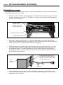
The remote control allows remote operation of the main burner. Follow the directions below to install.
1. With the gas shut off and the heater unplugged, remove the ashlip control housing by unscrewing
the three attachment screws with a 7/16" nutdriver. Carefully lay the ashlip control housing face
down in front of the heater.
Unscrew these three
bolts with a 7/16"
nutdriver to remove the
ashlip control housing
Ashlip Control Housing
Access Panel
2. Locate the 2" long green jumper wire. It can be found near the on/off switch. Remove the
jumper wire from the two green wires it attaches to (one leading to the on/off switch, the other to
the gas control valve).
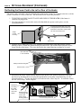
3. The remote control receiver wire enters the ashlip control housing in the same location the power
cord does. Use a pair of slip joint pliers to remove the strain relief that holds the power cord in
place (see the illustration below). Unwind the remote control receiver wire and route the end
with quick connects through strain relief and to a location near the on/off switch. Insert the strain
relief back in the hole until it snaps into place.
To remove the strain relief, use a pair
of slip joint pliers to press from the top
and bottom of the relief. Pull the relief
out once it becomes loose.
Ashlip
Control
Housing
Power Cord
4. Attach the thermostat wire to the two green wires that were detached in step 2. Make sure to
route the remote control receiver wire through the notch in the ashlip control housing partition if
it entered through the center or left side (see the illustration below).
Ashlip Control Housing
Route the thermostat through
the notch in the ashlip control
housing partition if it is coming
from the center or left side.
The thermostat wire attaches
to the green wire from the
valve and the green wire from
the on/off switch.
Red wire
from valve
Piezo
igniter
Orange wire from
spark electrode
Blower
Rheostat
On/Off
switch
Green wire
from valve
Green wire
Green Jumper wire
(remove and discard)
OPTIONAL EQUIPMENT (CONTINUED)
PAGE 33
Remote Control (continued)
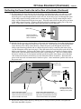
5. Replace the ashlip control housing. Make sure none of the wiring is pinched. Determine the
location of the remote control receiver. Find a location that is within reach of 10' of wire. Route
the remote control receiver wire to the location and connect it to the remote control receiver by
attaching the quick connects (the orientation of the wires does not matter).
6. Place a nine volt battery inside the remote control receiver and remote control (see the
illustration below).
This clip holds the
battery in place.
Remove this
screw with a
phillips head
screwdriver.
Attach the remote
control receiver
wire to these two
quick connects.
Mount a 9 volt battery in
both the remote control and
remote control receiver.
Remote
Control
Receiver
7. Mount the remote control receiver to the wall using two screws (not included). The screws pass
through the cover plate and hold the remote control receiver in place.
Remote Control Receiver
The hole must
be 1 3/4" wide.
Cover Plate
The hole must
be 2 1/2" tall.
The distance between the
mounting holes is 3 1/4".
The screws insert here (screws not included)
8. Test the remote control's operation prior to leaving the installation. Start the pilot, let it run five
minutes, then turn the on/off switch on the heater to "ON". Switch the remote control receiver to
"REMOTE". Press the remote control for one second to turn the heater on and off. If it does not,
check all of the electrical connections and re-test. When the remote control receiver is turned to
"ON" the heater will stay on, when on "OFF" the heater will stay off, regardless of the remote
control.
PAGE 34
OPTIONAL EQUIPMENT (CONTINUED)
Thermostat (Part # 99300650)
The thermostat allows the main burner to turn on and off automatically for consistent room temperature.
Follow the directions below to install.
1. With the gas shut off and the heater unplugged, remove the ashlip control housing by unscrewing
the three attachment screws with a 7/16" nutdriver. Carefully lay the ashlip control housing face
down in front of the heater.
Unscrew these three
bolts with a 7/16"
nutdriver to remove the
ashlip control housing
Ashlip Control Housing
Access Panel
2. Locate the 2" long green jumper wire. It can be found near the on/off switch. Remove the
jumper wire from the two green wires it attaches to (one leading to the on/off switch, the other to
the gas control valve - see the illustration on the following page).
3. The thermostat wire enters the ashlip control housing in the same location the power cord does.
Use a pair of slip joint pliers to remove the strain relief that holds the power cord in place (see
the illustration below). Unwind the thermostat wire and route the end with quick connects
through the strain relief and to a location near the on/off switch. Insert the strain relief back in
the hole until it snaps into place.
To remove the strain relief, use a pair
of slip joint pliers to press from the top
and bottom of the relief. Pull the relief
out once it becomes loose.
Ashlip
Control
Housing
Power Cord
4. Attach the thermostat wire to the two green wires that were detached in step 2. Make sure to
route the thermostat wire through the notch in the ashlip control housing partition if it entered
through the center or left side.
OPTIONAL EQUIPMENT (CONTINUED)
PAGE 35
Thermostat (continued)
Ashlip Control Housing
Red wire
from valve
Route the thermostat through
the notch in the ashlip control
housing partition if it is coming
from the center or left side.
The thermostat wire attaches
to the green wire from the
valve and the green wire from
the on/off switch.
Piezo
igniter
Orange wire from
spark electrode
Blower
Rheostat
On/Off
switch
Green wire
from valve
Green wire
Green Jumper wire
(remove and discard)
5. Replace the ashlip control housing. Make sure none of the wiring is pinched.
6. Determine the location of the thermostat. Find a location that is centralized in the room and
within reach of 50' of wire. Route the thermostat wire to the location and attach the thermostat
wire to the thermostat. Cut off any excess length of wire and expose approximately 1/2" of wire
for connection to the thermostat. Attach the thermostat wire to the two clips on the thermostat
using a standard screwdriver. Make sure the wire makes a good electrical contact.
Thermostat Back Side
Thermostat Front Side
To attach the
thermostat, pull
the cover off and
use the included
screws to hold it
against the wall.
Strip 1/2" off each
wire and attach the
exposed wire to the
clips using a standard
screwdriver.
Thermostat Wire
Holes used to attach the
thermostat to the wall.
7. Remove the cover of the thermostat by pulling it apart carefully. The thermostat has mounting
holes on each side of its base. Use the included screws to attach the thermostat to the wall. Tuck
any excess wire behind the thermostat and replace the thermostat cover.
8. Test the thermostat's operation prior to leaving the installation. Turn the thermostat to it's highest
position (all the way to the right). Start the pilot, let it run five minutes, then turn the on/off
switch on. The heater should turn on. If it does not, check all of the electrical connections and
re-test. The thermostat should turn the heater on when turned to its highest position, and turn off
when turned to its lowest position. NOTE: if the temperature in the room is not between 50° and
90° this will not work because of the thermostat's range. Wait until a suitable temperature is
achieved in the room before testing the thermostat.
PAGE 36
OPTIONAL EQUIPMENT (CONTINUED)
Re-Routing the Power Cord to the Left or Rear of the Heater
The power cord is normally routed to the right side of the heater. It may be re-routed to the left, or if the
heater is installed as a stove, at the rear. The directions below detail this procedure.
1. TURN THE GAS LINE VALVE TO OFF AND UNPLUG THE HEATER (if the heater is
connected or plugged in).
2. Use slip joint pliers to remove the strain relief that holds the power cord in place (see the
illustration below).
To remove the strain relief, use a pair
of slip joint pliers to press from the top
and bottom of the relief. Pull the relief
out once it becomes loose.
Ashlip
Control
Housing
Power Cord
3. Open the access panel and with a 7/16" nutdriver loosen the three bolts that hold the control
housing in place. When the control housing becomes loose, lift it off the bolts and place it face
down in front of the heater. The wires that lead to the control housing can then be accessed.
Loosen these
three bolts with
a 7/16" nutdriver
Ashlip Control Housing
Access Panel
4. Disconnect the molex connector that attaches to the power cord. Remove the power cord from
the heater by threading the molex plug through the hole in the ashlip control housing (see the
illustration below). To route the power cord to the left side, follow step 5A. To route the cord to
the rear (stoves only), follow step 5B.
This hole if
for routing
the power
cord to the
rear of the
heater.
Route the power
cord through this
notch in the
ashlip control
housing partition.
Blower
Rheostat
Disconnect the molex plug
to re-route the power cord.
OPTIONAL EQUIPMENT (CONTINUED)
PAGE 37
Re-Routing the Power Cord to the Left or Rear of the Heater (Continued)
5A Pry the button plug from the left side of the ashlip control housing using a screwdriver (see the
illustration below). Insert it in the hole on the right side where the strain relief was removed.
Insert the power cord through the hole on the left side. Route the power cord through the notch
in the ashlip control housing partition and re-connect the power cord by connecting the molex
plugs (see the illustration on the previous page). Place the strain relief over the power cord next
to the ashlip control housing. Compress the strain relief by clamping it with a pair of slip nose
pliers. Then insert it into the ashlip control housing until it locks into place.
Button Plug
Remove the button
plug by prying it loose
with a screwdriver
5B Included in the accessory pack are three cord mounts and a button plug. Insert the button plug in
the hole on the right where the strain relief was removed. Insert the power cord through the hole
on the bottom of the ashlip control housing. Route the power cord through the notch in the
ashlip control housing partition and re-connect the power cord by connecting the molex plugs
(see the illustration on the previous page). Place the strain relief over the power cord next to the
ashlip control housing. Compress the strain relief by clamping it with a pair of slip nose pliers.
Then insert it into the ashlip control housing until it locks into place. The cord is hidden under
the heater with the use of cord mounts inserted into the baseplate of the heater. Insert the three
cord mounts into the base of the heater (see the illustration below for details). Then insert the
power cord into each cord mount until it latches in place. After installation, pull the slack out of
the power cord.
Ashlip Control Housing
Power Cord
Strain Relief
Cord mount
Fr
o
o
nt
fS
to
ve
Baseplate
Insert this end in
until these barbs
expand, locking
it in place.
Insert the power cord
through these two arms
until they lock in place.
FOR STOVES WITH LEGS
Insert a cord mount into the hole in the
center of the stove and route the cord
down the middle of the stove.
FOR STOVES WITH PEDESTALS
Insert a cord mount into the hole on the
right side of the pedestal and route the
cord around the base of the pedestal.
6. Replace the ashlip control housing, making sure no wiring becomes pinched, and tighten the
three bolts that hold it in place.
PAGE 38
INDEX
B Vent (insert) .............................................................. 11
On/Off Operation ......................................................... 18
B vent (stove) ............................................................... 7
Operating Sounds ....................................................... 19
Blower Speed ............................................................... 19
Operating the Heater .................................................... 17
BTU Input ..................................................................... 5
Paint Curing................................................................. 17
Cap (vent termination - insert)...................................... 12
Parts List ..................................................................... 26
Cap (vent termination - stove)...................................... 8
Pedestal (installation) ................................................... 29
Clearances (insert) ....................................................... 10
Pilot (starting) ............................................................... 16
Clearances (stove) ....................................................... 6
Power Cord (re-routing to rear or left of heater) ........... 36
Controls........................................................................ 15
Propane Line Install (gas line install - insert)............... 12
Dimensions................................................................... 5
Propane Line Install (gas line install - stove) ................ 8
Door (inspection, removal, replacing components)...... 22
Propane Verses Natural Gas Heater........................... 2
Door Gasket ................................................................. 22
Purging Gas Line (insert) ............................................. 13
Emissions ..................................................................... 5
Purging Gas Line (stove)............................................. 9
Fan Speed ................................................................... 19
Remote Control (installation) ....................................... 32
Firebox (inspection) ..................................................... 20
Remote Control (operation) .......................................... 18
Fireplace Sizing ........................................................... 11
Replacement Parts...................................................... 26
Flame Height................................................................ 19
Reviewing the Installation ............................................ 14
Flexible Tube Note (insert) ........................................... 12
Running Your Heater................................................... 17
Flexible Tube Note (stove) ........................................... 8
Safety Label ................................................................. 28
Floor Protection (insert)................................................ 11
Safety Precautions ...................................................... 2
Floor Protection (stove)................................................ 7
Sounds (normal operating sounds) .............................. 19
Fuel .............................................................................. 5
Starting The Pilot .......................................................... 16
Gas Inlet Location (insert) ............................................ 12
Starting the Heater for the First Time ........................... 17
Gas Inlet Location (stove) ............................................ 8
Stove Clearances ......................................................... 6
Gas Leak............................................ See Inst. on Cover
Surround Panels (installation) ...................................... 30
Gas Line Install (insert) ................................................ 12
Table of Contents ......................................................... 4
Gas Line Install (stove) ................................................ 8
Telescoping Legs (installation).................................... 31
Gas Pressure (insert) ................................................... 13
Thermostat (installation)............................................... 34
Gas Pressure (stove) ................................................... 9
Thermostat (operation)................................................ 18
Gas Smell............................................ See Inst. on Cover
Troubleshooting Table................................................. 23
Glass, Glass Gasket .................................................... 22
Turning the Heater On and Off.................................... 18
Heater Placement (insert) ............................................ 10
Vent Requirements (insert) ......................................... 11
Heater Placement (stove) ............................................ 6
Vent Requirements (stove) .......................................... 7
Heating Specifications ................................................. 5
Vent termination (insert) ............................................... 12
How this Heater Works................................................. 24
Vent termination (stove) .............................................. 8
Leaking Gas ....................................... See Inst. on Cover
Warranty....................................................................... 27
Legs (installation) ......................................................... 29
Weight .......................................................................... 5
Listing Information........................................................ 28
What Prevents Gas Buildup ........................................ 25
Logs and Coals (installation, removal) ......................... 21
What Turns the Main Burners On and Off .................... 24
Manifold Pressure (insert) ............................................ 13
Why Nothing Should Be Placed Against the Heater ... 24
Manifold Pressure (stove) ............................................ 9
Wiring Diagram............................................................ 26
Natural Gas Verses Propane Heater ........................... 2