1
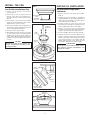
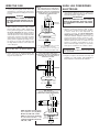
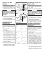
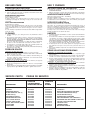
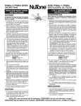
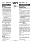
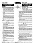
PFKB52 SERIES
CEILING FANS
SERIE PFKB52 VENTILADORS
DE TECHO
READ AND SAVE THESE
INSTRUCTIONS
WARNING
LEA Y GUARDE ESTAS
INSTRUCCIONES
ADVERTENTCIA
TO REDUCE THE RISK OF FIRE, ELECTRICAL
SHOCK, OR INJURY TO PERSONS, OBSERVE
THE FOLLOWING:
1. Use this unit only in the manner intended by the
manufacturer. If you have questions, contact
the manufacturer at the address or telephone
number listed in the warranty.
2. Before servicing or cleaning unit, or installing a
light kit, switch power off at service panel and
lock service panel to prevent power from being
switched on accidentally. When the service disconnecting means cannot be locked, securely
fasten a prominent warning device, such as a
tag, to the service panel.
3. Installation work and electrical wiring must be
done by a qualified person(s) in accordance
with all applicable codes and standards, including fire-rated construction codes and standards.
4. If the fan will be mounted to a ceiling box, the
box and its support must be able to support
the moving weight of the fan (at least 35 lbs.).
The box must not twist or work loose. DO
NOT USE PLASTIC OUTLET BOXES.
WARNING: To reduce the risk of fire, electric
shock, or personal injury, mount to outlet box
marked acceptable for fan support and use
mounting screws provided with outlet box.
5. If the fan will be mounted to a ceiling joist, the
joist must be able to support the moving weight
of the fan (at least 35 lbs.).
The weight of your fan is listed below. The weights
of light kits, down rods, and ceiling adapters are
listed in the instructions packed with those accessories.
FAN SERIES
PFKB52 18.6 lbs.
PARA REDUCIR EL RIESGO DE INCENDIO, GOLPE
ELECTRICO, O HERIDA A PERSONAS, OBSERVESE LO
SIGUIENTE:
1. Solamente use esta unidad de la manera propuesta por el
fabricante. Si tiene alguna pregunta, póngase en contacto
con el fabricante en la dirección o teléfono anotados en la
garantía.
2. Antes de limpiar o dar servicio a la unidad, o instalar un
juego de luces, corte la potencia en el panel de servicio y
tránquelo para evitar que ésta resuma accidentalmente.
Cuando el dispositivo para desconectar el servicio eléctrico
no puede ser cerrado con algún tipo de traba, sujete
fuertemente al panel de servicio, una etiqueta de
advertencia prominente.
3. El trabajo de instalación y el cableado eléctrico deben de
llevarse a cabo por personal calificado de acuerdo con
todos los códigos y las normas aplicables, incluyendo los
códigos y normas de construcción contra incendios.
4. Si el ventilador va a instalarse en una caja de techo, la
caja y su soporte deben ser capaces de soportar el
peso del ventilador en movimiento (por lo menos 15.9
kg.). La caja no debe bambolear o zafarse. NO UTILICE
LAS CAJAS PLÁSTICAS DEL ENCHUFE.
ADVERTENCIA: Para reducir el riesgo de incendio,
golpe electrico, o herida a personas, montelo en caja de
techo marcada aceptable para soportar ventilador y
uso tornillos de montaje suministran con caja de techo.
5. Si el ventilador va a instalarse en una vigueta de techo
la vigueta debe ser capaz de soportar el peso del
ventilador en movimiento (por lo menos 15.9 kg.).
A continuación se indica el peso de su ventilador. El peso
de los juegos de lámparas, varillas de descenso y
adaptadores para cielo raso se lista en las instrucciones
que vienen con estos accesorios.
VENTILADOR SERIE
PFKB52 8.5 kg
6. When cutting or drilling into wall or ceiling, do not
damage electrical wiring and other hidden utilities.
7. This unit must be grounded.
8. After installation is complete, make sure that all
connections are secure to prevent the fan from
falling. Make sure all wire connections are secure, and that there are no exposed conductor
strands.
9. WARNING: TO REDUCE THE RISK OF PERSONAL INJURY, DO NOT BEND THE BLADE
BRACKETS WHEN INSTALLING THE BRACKETS, BALANCING THE BLADES, OR CLEANING THE FAN. DO NOT INSERT FOREIGN
OBJECTS IN BETWEEN ROTATING FAN
BLADES.
10.Make sure that your installation will not allow the
fan to come into contact with any adjacent obstacles such as doors, hanging lamps, etc.
11.If you are installing more than one ceiling fan, do
not mix the blade sets.
12.The fan must be mounted with at least 7 feet of
clearance between fan blades and floor.
6. Al cortar o taladrar en una pared o cielo raso, no dañe el
cableado eléctrico u otras instalaciones no visibles.
7. Esta unidad debe estar conectada a tierra.
8. Después de completar la instalación asegúrese que todas
las conexiones están firmes para evitar que el ventilador
se caiga. Asegúrese que todas las conexiones de alambres
estén bien hechas y que no hay hilos expuestos.
9. ADVERTENCIA: PARA DISMINUIR EL PELIGRO DE
DAÑOS CORPORALES NO DUEBLE LOS SOPORTES
DE LAS ASPAS CUANDO LOS INSTALE, EQUILIBRE LAS
ASPAS, O LIMPIE EL VENTILADOR. NO INTRODUZCA
OBJETOS EXTRAÑOS ENTRE LAS ASPAS EN
MOVIMIENTO.
10.
Asegúrese que la instalación permita al ventilador
rotar libremente sin tocar ningún obstáculo, tales como
puertas, lámparas colgantes, etc.
11.Si va a instalar más de un ventilador no mezcle los juegos
de aspas.
12.
El ventilador debe instalarse dejando un claro o
espacio de por lo menos 213 cm entre el piso y las aspas
del ventilador.
CAUTION
1. Para evitar daños al cojinete del motor y/o impuldores
ruidosos o desequilibrados, mantenga la fuente de
potencia lejos de rocíos de pared de yeso, de polvo de
construcción, etc.
2. Lea la etiqueta de especificaciones del producto para
más información y requisitos.
1. To avoid motor bearing damage and noisy and/
or unbalanced impellers, keep drywall spray,
construction dust, etc. off power unit.
2. Please read specification label on product for
further information and requirements.
PRECAUCION
INSTALLER: Leave this manual with the homeowner. HOMEOWNER: Use and care instructions on page 7.
INSTALADOR: Deje este Manual con el Propietario. PROPIETARIO: Información Sobre el Uso y Cuidado en la Página 7.
UNPACK THE FAN
Unpack fan and check contents. You should receive:
1 - Fan motor
DESEMPAQUE EL
VENTILADOR
FIG. 1
CEILING
TECHO
Leave motor in box for now.
Packing materials will protect
housing finish.
1 - Canopy
5 - Blade Top Brackets
5 - Blade Bottom Brackets
5 - Blades
1 - Downrod
1 - Fan mounting bracket
1 - Plastic bag containing:
15 - Blade mounting screws
10 - Blade bracket mounting screws
1 - Downrod pin
1 - Cotter pin for downrod pin
4 - Canopy mounting screws
3 - Wire nuts
1 - Wood bead with chain
2. - Wood Screws
PREPARE THE
LOCATION
1. Choose a location for mounting the fan where
the blades will be at least 7 feet from the floor.
(FIG. 1) Additional clearance can be obtained
(FIG. 2) by using the low profile installation
described on page 3.
2. TURN OFF POWER AT SERVICE ENTRANCE
BEFORE BEGINNING.
3. Check ceiling box. Add additional support, such
as a 2x4 between joists, if necessary. Use wood
screws to secure ceiling box to building structure. (FIG. 3)
WARNING
DO NOT MOUNT FAN TO CEILING MATERIAL ONLY! TO REDUCE THE RISK OF
FIRE, ELECTRIC SHOCK, OR PERSONAL
INJURY, MOUNT TO CEILING BOX
MARKED ACCEPTABLE FOR FAN SUPPORT. THE BOX AND ITS SUPPORT MUST
BE ABLE TO SUPPORT THE MOVING
WEIGHT OF THE FAN AND LIGHTS (AT
LEAST 35 LBS.). THE BOX MUST NOT
TWIST OR WORK LOOSE.
4. Fasten fan mounting bracket to ceiling box.
Use locking screws provided with outlet box.
(FIG. 3)
10¾” - 27.3cm
1 - Motor de ventilador -
7 FEET MINIMUM
MINIMO 213 cm
FLOOR
PISO
FIG. 2
CEILING
TECHO
7½” - 19.1cm
7 FEET MINIMUM
MINIMO 213 cm
FLOOR
PISO
FIG. 3
No lo saque de la caja
ahora-los materiales de
relleno protejerán el
acabado de la carcasa.
1 - Cúpola
5 - Soportes de las aspas parte superior
5 - Soportes de las aspas fondo
5 - Aspas
1 - Varilla hueca
1 - Ménsula de montaje de ventilador
1 - Bolsita de plástico que contiene:
15 - Tornillos para montar las aspas
10 - Tornillos para asegurar los soportes a
las aspas
1 - Pasador de la varilla
1 - Clavija hendida para el pasador
4 - Tornillos para montar la cúpola
3 - Conectores para alambre
1 - Esferita de madera con cadena
2 - Tornillos de madera
SECURING CEILING BOX TO A JOIST
COMO ASEGURAR LA CAJA DE TECHO A UNA VIGUETA
JOIST
VIGUETA
ADDITIONAL SUPPORT
SOPORTE ADICIONAL
ADD WOOD SCREWS TO
REINFORCE BOX
UTILICE TORNILLOS PARA MADERA
PARA REFORZAR LA CAJA
LOCKING SCREWS
TORNILLOS DE
SUJECION
FAN MOUNTING
BRACKET
MENSULA DE MANTAJE
DEL VENTILADOR
SECURING CEILING BOX BETWEEN JOISTS
COMO ASEGURAR LA CAJA DE TECHO INSTALADA ENTRE
VIGUETAS
ADDITIONAL SUPPORT
DO NOT RELY ON
SOPORTE ADICIONAL
BAR
BAR HANGER
JOIST
HANGER
ALONE TO
VIGUETA
COLGADOR
SUPPORT FAN
DE BARRA
NO SE CONFIE EN
ADD WOOD
EL COLGADOR DE
SCREWS TO
BARRA SOLAMENTE
REINFORCE BOX
PARA SOPORTAR
UTILICE
EL VENTILADOR
TORNILLOS
PARA MADERA
PARA REFORZAR
LA CAJA
FAN MOUNTING BRACKET
MENSULA DE MANTAJE DEL
VENTILADOR
LOCKING SCREWS
TORNILLOS DE SUJECION
FIG. 4
ADD WOOD SCREWS TO REINFORCE BOX
UTILICE TORNILLOS PARA
MADERA PARA REFORZAR
LA CAJA
JOIST
VIGUETA
CROSS BRACE
PUNTAL
CRUZADO
CAUTION
To reduce the risk of personal injury, use
only the two steel locking screws provided
with the ceiling box.
Desempaque el ventilador y examine el contenido.
Deberá recibir:
OPENING ON FAN
MOUNTING BRACKET
TOWARD TOP
EL ORIFICIO EN LA
MENSULA DE MONTAJE
DEL VENTILADOR
HACIA ARRIBA
LOCKING SCREWS
TORNILLOS DE
SUJECION
PREPARE EL LUGAR
1. Escoja un lugar para instalar el ventilador donde
las aspas queden a lo menos a 213 cm del piso.
(FIG. 1) Puede conseguirse mayor distancia (FIG.
2) empleando la instalación de perfil bajo que se
describe en la página 3.
2. ¡CORTE LA CORRIENTE ELECTRICA EN EL
SERVICIO DE ENTRADA ANTES DE COMENZAR
EL TRABAJO!
3. Chequee la caja de distribución. Si fuera necesario
refúercela agregando maderos 2 x 4 entre las
viguetas. Emplee tornillos para madera para
asegurar la caja a la estructura del edificío. (FIG.
3)
ADVERTENCIA
¡NO INSTALE EL VENTILADOR SIMPLEMENTE
ASEGURANDOLO AL MATERIAL DEL TECHO!
PARA DISMINUIR EL PELIGRO DE INCENDIO,
SACUDIDA ELECTRICA, O DAÑO CORPORAL,
MONTELO EN CAJA DE TECHO MARCADA
ACEPTABLE PARA SOPORTAR VENTILADOR.
LA CAJA Y SU SOPORTE DEBEN SER CAPACES
DE SOPORTAR EL PESO DEL VENTILADOR Y
LAS LUCES EN MOVIMIENTO (A LO MENOS
15.9 KG.). LA CAJA N0 DEBE BAMBOLEAR O
ZAFARSE.
4. Asegure la ménsula de montaje del ventilador a la
caja de techo. Emplee los tornillos de sujeción que
vienen con la caja de techo. (FIG. 3)
PRECAUCION
5. FOR SLOPED CEILING INSTALLATIONS
ONLY: Ball and socket mounting system will
work on sloped ceilings up to 22 o maximum
(rise/run = 5/12) (FIG. 4).
Para reducir el peligro de daño corporal, use
solamente los dos tornillos de acero de
sujeción que vienen con la caja de techo.
A ceiling steeper than 22o requires that a mounting surface be constructed.
5. Para Instalaciones de Techo Inclinado
SOLAMENTE: El sistema de montaje de rótula
esférica queda bien en techos inclinados hasta un
máximo de 22° (elevación/carrera = 5/12) (FIG.
4.) Un techo inclinado más de 22° requiere la
construcción de una superficie de montaje.
2
INSTALL THE FAN
INSTALE EL VENTILADOR
FIG. 5
DOWNROD
SETSCREW
TORNILLO DE
AJUSTE DE LA
VARILLA
Downrod Installations Only
1. Turn fan motor on its side so that you can see
wires. Leave it in the box for now, so that packing will protect housing finish. Lead wires are
long enough to accomodate installations utilizing 48” downrods and must be cut to required
length.
CAUTION
DOWNROD
VARILLA HUECA
CANOPY
CUPOLA
DOWNROD PIN
PASADOR DE LA
VARILLA HUECA
COTTER PIN
CLAVIJA HENDIDA
DO NOT assemble fan with fan motor in an
upright position. Small parts may drop into
the motor housing and you may not be able
to get them out. Assemble the fan with the
fan motor on its side. DO NOT install blades
at this time!
2. Place downrod through canopy, then feed wires
from top of motor through downrod. (FIG. 5)
DO NOT FORCE DOWNROD PIN THROUGH
DOWNROD - WIRES INSIDE DOWNROD MAY
BE DAMAGED.
1. Dé vuelta el motor y póngalo en el lado que permite
ver los alambres. Déjelo por ahora en la caja. El
relleno protejerá el acabado de la carcasa. Los
conductores eléctricos son suficientemente largos
como para permitir instalaciones que llevan varillas
huecas de 1219 mm que pueden cortarse al largo
requerido.
PRECAUCION
NO ARME el ventilador con el motor en posición
vertical. Las piezas pequeñas pueden caerse
dentro de la caja del motor de donde es imposible
sacarlas. Arme el ventilador con el motor en su
costado. ¡NO INSTALE las aspas todavía!
COUPLING
ACOPLE
3. Align holes in motor coupling with holes in bottom of downrod. Insert downrod pin through
downrod.
WARNING
SOLAMENTE LAS
INSTALACIONES DE VARILLA
HUECA
2. Coloque la varilla hueca a través de la cúpola y
luego corra los alambres por el tope del motor bacia
abajo por dentro de la varilla. (FIG. 5)
FIG. 6
3. Alinee los agujeros en el acople del motor con los
agujeros en la parte inferior de la varilla. Inserte el
pasador a través de la varilla.
MOUNTING
BRACKET
MENSULA DE
MONTAJE
ADVERTENCIA
4. Insert cotter pin through downrod pin and bend
ends of cotter pin back so that pin will not fall
out. (FIG. 5)
NO FUERCE EL PASADOR A TRAVES DE LA
VARILLA - PUEDE PINCHAR LOS ALAMBRES
QUE CORREN DENTRO DE LA VARILLA.
5. Tighten downrod set screws securely. (FIG. 5)
6. Lift fan onto fan mounting bracket. Tab opposite opening on fan mounting bracket should fit
into slot on ball. (FIG. 6) Make sure wires are
not pinched between ball and fan mounting
bracket.
CANOPY
CUPOLA
4. Inserte la clavija hendida a través del pasador y
dueble los extrenos de la clavija para que el pasador
no se salga. (FIG. 5)
5. Apriete bien el tornillo de ajuste de la varilla. (FIG. 5)
6. Levante el ventilador y colóquelo en la ménsula de
montaje. La uña opuesta al orificio en la ménsula
de montaje deberá caber en la ranura de la bola.
(FIG. 6) Asegúrese que los alambres no estén
pinchados entre la bola y la ménsula de montaje.
3
INSTALL THE FAN
INSTALE EL VENTILADOR
FIG. 7
Low Profile Installations Only
Instalaciones de bajo perfil
solamente
1. Remove canopy bottom cover from the
canopy. (FIG. 7)
2. Remove three of the six screws and lockwashers (every other one) securing the motor collar to the top of the fan motor housing.
(FIG. 8).
3. Place canopy on top of motor housing, align
the three holes and reinstall the three screws.
Tighten all three screws securely.
1. Qute la cubierta del escudete del escudete.
(FIG. 7)
CANOPY BOTTOM
COVER
2. Remover tres de los seis tornillos y arandelas de
seguirdad (dejando uno por medio) asegurando el
collarín del motor localizado en la parte superior
de la cubierta del motor. (FIG. 8)
CUBIERTA DEL
ESCUDETE
FIG. 8
4. Place motor assembly onto mounting bracket.
The hole in the canopy should hang on the hook
on the mounting bracket. (FIG. 9)
SCREWS (3)
TORNILLOS (3)
5. Cut motor wires to proper length.
6. After making electrical connections, (See page
5), push canopy up onto mounting bracket
and turn motor so slots in canopy engage two
screws. (FIG. 10) Tighten both screws, then
install two other screws. Tighten all four screws
securely.
CANOPY
CUPOLA
CAUTION
COUPLING
ACOPLE
3. Coloque la cúpola en el tope de la carcasa del
motor, alinee los tres agujeros y reponga los cuatro
tornillos. Apriete bien todos los tres tornillos.
4. Coloque el conjunto motor en la ménsula de
montaje. El hueco de la cúpola deberá insertar en
el gancho de la ménsula de montaje. (FIG. 9)
5. Corte los alambres del motor al largo requerido.
6. Después de hacer las conexiones eléctricas (vea
la pág. 5) empuje la cúpola hacia la ménsula de
montaje y dé vuelta el motor hasta que la ranura
de la cúpola enganche los dos tornillos. (FIG. 10)
Apriete ambos tornillos y luego instale los otros
dos tornillos. Apriete bien los cuatro tornillos.
At least four screws must be used to fasten the canopy/motor assembly to the
mounting bracket.
PRECAUCION
Por lo menos cuatro tornillos deben usarse
para sujetar el conjunto cúpola/motor a la
ménsula de montaje.
FIG. 9
HOOK
GANCHO
MOUNTING
BRACKET
MENSULA DE
MONTAJE
CANOPY
CUPOLA
MOTOR ASSEMBLY
CONJUNTO MOTOR
FIG. 10
SCREWS (4)
TORNILLOS (4)
SLOT
RANURA
CANOPY
CUPOLA
4
FAN CONTROLLED BY PULL CHAIN SWITCH.
LIGHT CONTROLLED BY PULL CHAIN SWITCH.
VENTILADOR CONTROLADO POR INTERRUPTOR
A CADENILLA DE TIRO. LUZ CONTROLADA POR
INTERRUPTOR A CADENILLA DE TIRO.
BLACK
NEGRO
TURN OFF ELECTIC POWER AT SERVICE
ENTRANCE BEFORE MAKING ELECTRICAL CONNECTIONS OR INSTALLING A
LIGHT KIT.
Red or Blue wire is for optional light kit.
3. Fasten canopy to fan mounting bracket with
four screws. (FIG. 10) Remove the plastic
bag from around the fan.
GROUND
TIERRA
BLACK
NEGRO
BLUE OR RED
AZUL O ROJO
FAN
VENTILADOR
BLUE OR RED
AZUL O ROJO
WHITE - BLANCO
BLACK - NEGRO
WHITE - BLANCO
LIGHT
LUZ
Do not connect RED or BLUE if light is not installed.
Wire nut end of RED or BLUE wire.
No conecte el ROJO o AZUL si no ha instalado la luz.
El conector va al final del alambre ROJO o AZUL.
FAN CONTROLLED BY PULL CHAIN SWITCH.
LIGHT CONTROLLED BY WALL SWITCH.
VENTILADOR CONTROLADO POR INTERRUPTOR
A CADENA DE TIRO. LUZ CONTROLADA POR
INTERRUPTOR DE PARED.
GROUND
TIERRA
WHITE
BLANCO
BLACK
NEGRO
LINE
LINEA
LIGHT
SWITCH
INTERRUPTOR
DE LUZ
GROUND
TIERRA
WHITE
BLANCO
BLACK
NEGRO
BLUE OR RED
AZUL O ROJO
CEILING BOX
CAJA DE TECHO
FAN
VENTILADOR
BLUE OR RED
AZUL O ROJO
WHITE - BLANCO
BLACK - NEGRO
WHITE - BLANCO
LIGHT
LUZ
NOTA: Si se desea un ventilador
de velocidad variable - use
solamente los Modelos Broan 78V,
78W, 79V, o 79W.
WHITE-BLANCO
GROUND-TIERRA
WHITE-BLANCO
BLACK-NEGRO
BLUE OR RED
AZUL O ROJO
NOTE: If variable speed fan operation is desired - use only Broan
Models 78V, 78W, 79V, or 79W.
FAN
VENTILADOR
LINE
LINEA
GROUND-TIERRA
BLACK-NEGRO
FAN AND LIGHT CONTROLLED BY INDEPENDENT
WALL SWITCHES.
VENTILADOR Y LUZ CONTROLADOS POR
INTERRUPTORES DE PARED INDEPENDIENTES.
LIGHT
LUZ
CEILING
BOX
CAJA
DE TECHO
FAN
VENTILADOR
BLUE OR RED
AZUL O ROJO
WHITE - BLANCO
WHITE - BLANCO
BLACK - NEGRO
LIGHT
LUZ
5
HAGA LAS CONEXIONES
ELECTRICAS
1. Use la bolsa de plástico en que vino el motor para
cubrir la parte superior del motor a fin de evitar que
las piezas pequeñas caigan dentro.
ADVERTENCIA
CEILING BOX
CAJA DE TECHO
2. Make electrical connections. (FIG. 11) Wire
black to black, white to white, and green to
house ground using proper connections. FAN
MUST BE GROUNDED. All splices and wires
should be pushed back into ceiling box so they
will not be pinched or cut by canopy. After making the wire connections, the wires should be
spread apart with the grounded conductor
(white) and the equipment-grounding conductor (green) on one side of the ceiling box and
the ungrounded conductors on the other side
of the ceiling box.
NOTE
GROUND
TIERRA
LINE
LINEA
WARNING
WHITE
BLANCO
1. Use the plastic bag that the fan motor was
packaged in to cover up the top of the motor to
prevent small parts from falling into the motor
housing.
FIG. 11
WHITE
BLANCO
WIRE THE FAN
CORTE LA CORRIENTE ELECTRICA EN EL
SERVICIO DE ENTRADA ANTES DE HACER
LAS CONEXIONES ELECTRICAS O INSTALAR
LAS LUCES.
2. Haga las conexiones eléctricas. (FIG. 11) Conductor negro a conductor negro, blanco a blanco,
y verde a tierra de la casa empleando las
conexiones correctas. EL VENTILADOR DEBE
CONECTARSE A TIERRA. Todos los empalmes y
conductores deberán empujarse dentro de la caja
de techo para que la cúpola no los pinche o corte.
Después de hacer las conexiones, los alambres
deberán separarse poniendo en un lado de la caja
de techo el conductor a tierra (blanco) y el conductor a tierra del equipo (verde) y en el otro lado
de la caja los conductores sin conexión a tierra.
NOTA
El conductor rojo o azul es para el juego de
luces opcionales.
3. Asegure la cúpola a la ménsula de montaje del
ventilador con cuatro tornillos. (FIG. 10) Quite la
bolsa de plástico de alrededor del ventilador.
INSTALL THE FAN
BLADES
1. Fasten blades to blade brackets. Make sure
that blade mounting screws are tightened firmly
into blade bottom backets. (FIG. 12)
2. Fasten blade brackets to fan motor. Tighten
blade bracket mounting screws firmly. (FIG.
13)
INSTALE LAS ASPAS DEL
VENTILADOR
FIG. 12
BLADE MOUNTING
SCREWS
TORNILLOS PARA MONTAR
LA ASPA
BLADE TOP BRACKET
SOPORTE DE LA
ASPA SUPERIOR
CAUTION
The blades and blade brackets have been
carefully balanced to prevent wobble when
the fan is operating. Handle blades and
brackets carefully to avoid bending them.
Bent blade brackets are the primary cause
of fan wobble.
BLADE
ASPA
FIG. 13
3. Install optional light kit at this time. Follow the
instructions packed with the kit. USE ONLY A
U.L. LISTED LIGHT KIT MARKED FOR USE
WITH THIS CEILING FAN MODEL.
4. Turn on power and check operation of fan and
light kit, if fan is so equipped.
BLADE BALANCING
INFORMATION
All blades are grouped by weight. Natural woods
vary in density, which could cause the fan to wobble
slightly, even though all blades are weight-matched.
The procedures listed below should eliminate any
wobble.
BLADE
BOTTOM
BRACKET
SOPORTE
DE LA
ASPA
FONDO
1. Asegure las aspas a sus soportes. Asegúrese
que los tornillos de montaje de las aspas estén
firmemente apretados dentro de los soportes
fondos. (FIG.12)
2. Asegure los soportes al motor del ventilador.
Apriete bien los tornillos de montaje. (FIG. 13)
PRECAUCION
Las aspas y los soportes se han equilibrado
con cuidado para evitar el bamboleo cuando
funciona el ventilador. Maneje las aspas y
soportes cuidadosamente para no torcerlos.
Soportes torcidos son la causa principal del
bamboleo del ventilador.
3. Instale ahora el juego de luces opcionales. Siga
las instrucciones que vienen con el juego. USE
SOLAMENTE UN JUEGO DE LUCES DE LISTA
U.L. INDICADO PARA USARSE CON ESTE
MODELO DE VENTILADOR DE TECHO.
BLADE BRACKET
MOUNTING SCREWS
TORNILLOS PARA
ASEGURAR LOS
SOPORTES A LAS ASPAS
4. Conecte la electricidad y chequee el funcionamiento
del ventilador y el juego de luces si el ventilador
lleva luces.
INFORMACION SOBRE LA
MANERA DE EQUILIBRAR
LAS ASPAS
FIG. 14
1. Make sure that all blades are screwed firmly to
blade brackets.
Todas las aspas se agrupan por peso. Las maderas
naturales varían en densidad, lo cual puede hacer que
el ventilador bambolee ligeramente pese a que todas
las aspas concuerdan en peso. El procedimiento
indicado abajo eliminará el bamboleo.
2. Make sure that all blade brackets are screwed
firmly to fan motor.
1. Asegúrese que todas las aspas estén bien
atornilladas a los soportes.
3. If fan is equipped with light kit, make sure that
fitter is screwed firmly into switch box cover.
Center shade in fitter by adjusting thumbscrews.
2. Asegúrese que todos los soportes estén bien
atornillados al motor.
3. Si el ventilador lleva luces asegúrese que el
adaptador esté firmemente atornillado a la tapa de
la caja del interruptor. Centre la pantalla ajustando
los tornillos de apriete manual.
4. If the previous steps do not eliminate the
wobble, the problem is possibly a bent blade
bracket or a warped blade. This can be determined by viewing each blade at its outer edge
with the fan running. A blade out of alignment
will be easy to see - there will be differences in
height at the blade tips while the fan is running.
Remember that stopping the blades suddenly
with your hand will probably bend the blade
bracket. A bent blade bracket or a warped blade
must be replaced. Contact your Broan
representitive for replacement.
4. Si el procedimiento indicado arriba no elimina el
bamboleo, el problema posiblemente se debe a un
soporte de aspa torcido o a una aspa deformada.
Esto puede determinarse mirando el borde exterior
de cada aspa con el ventilador en funcionamiento.
Una aspa desalineada se ve fácilmente - se notará
diferencias en la altura en las puntas de la aspa
mientras funciona el ventilador. Recuerde Ud. que
si para las aspas repentinamente con la mano ello
probablemente torcerá el soporte. Un soporte
torcido o una aspa alabeada deben reemplazarse.
Póngase en contacto con el Representante de
Broan con respecto al reemplazo.
5. If the previous step does not reveal a bent blade
bracket or a warped blade, it may be possible
to eliminate any wobble by interchanging the
blade/blade bracket assemblies as shown. Follow the order shown and check for wobble after each switch. (FIG. 14)
5. Si el procedimiento anterior no descubre un soporte
torcido o una aspa alabeada es posible eliminar el
alabeo intercambiando la posición de los conjuntos
de aspa/aspa soporte como se muestra. Siga el
orden indicado y vea si hay alabeo después de cada
intercambio. (FIG. 14)
6
USE AND CARE
USO Y CUIDADO
OPERATING INSTRUCTIONS
INSTRUCCIONES DE OPERACION
1. The operating sequence for the pull chain switch is OFF - HIGH MEDIUM - LOW.
2. Push the slide switch one way for upward air movement and the other
way for downward air movement.
1. El orden de operación del interruptor a cadena de tiro es APAGADOALTO-MEDIANO-BAJO.
2. Empuje el interruptor corredizo hacia un lado para dirigir el movimiento
del aire hacia arriba y hacia el otro lado para mover el aire hacia abajo.
WARM WEATHER OPERATION
OPERACION EN TIEMPO CALIENTE
Air flow direction - Downward
Speed - Medium to High
In warmer weather, your ceiling fan will let you reduce your use of air
conditioning by keeping the air moving to help you feel cooler and more
comfortable.
Dirección de la Corriente de Aire - Hacia Abajo
Velocidad - Mediana a Alta
En tiempo caliente su ventilador de techo le permitirá reducir el uso del
acondicionador de aire manteniendo el aire en movimiento para ayudarle
a sentirse más fresco y más cómodo.
COOL WEATHER OPERATION
OPERACION EN TIEMPO FRESCO
Air flow direction - Upward
Speed - The exact speed will depend on the size of the room, the number
of fans, the ceiling height, etc. Fan speed should be fast enough to break
up air stratification in the room, but slow enough so as not to create a
breeze.
In cooler weather, an upward air flow reduces drafts while moving warmer
air off the ceiling.
Dirección de la Corriente de Aire - Hacia Arriba
Velocidad - La velocidad exacta dependerá del tamaño del cuarto, el
número de ventiladores, la altura del techo, etc. La velocidad del ventilador
deberá ser suficientemente rápida para romper la estratificación del aire en
el cuarto pero suficientemente lenta para no crear una brisa.
En tiempo fresco una corriente de aire hacia arriba reduce las ráfagas
mientras desplaza el aire caliente del techo.
CLEANING
LIMPIEZA
1. Periodic cleaning of your ceiling fan is the only maintenance that is
needed.
2. The housing is sealed with a lacquer to prevent any discoloration or
tarnishing. Therefore, use only a soft cloth or brush to avoid scratching
the finish. DO NOT USE SCOURING POWDERS, HARSH ALKALIS OR
DISHWASHING DETERGENTS.
Do not use water when cleaning your ceiling fan. Water could damage
the motor or the wood blades and could cause an electric shock.
3. You may wish to occasionally apply a light coat of furniture polish to the
wood blades to protect and enhance their beauty.
4. The fan motor is equipped with permanently lubricated ball bearings,
and will never need oiling.
1. La limpieza periódica del ventilador es el único servicio de mantenimiento
que se necesita.
2. La carcasa viene sellada con una laca que impide el descoloramiento
o las manchas. Por lo tanto, emplee solamente un trapo suave o cepillo
a fin de no rayar el acabado. NO EMPLEE POLVOS PARA FREGAR,
ALCALINOS FUERTES O DETERGENTES LAVAPLATOS.
No use agua para limpiar su ventilador. El agua puede arruinar el motor
o las aspas de madera aparte de darle un sacudón eléctrico.
3. Si desea puede de vez en cuando aplicar una capa ligera de lustre
para madera a las aspas como protección y para dar realce a su
belleza.
4. El motor del ventilador está provisto de conjinetes de bola de lubricación
permanente.
PROBLEM SOLVER
COMO SOLUCIONAR PROBLEMAS
PROBLEM: FAN WILL NOT START
1. Check fuse or circuit breaker and replace or reset if necessary.
2. Check that pull chain switch is on and that slide switch is either all the
way to one side or the other.
3. Turn off electrical power at the service entrance. Check all wiring connections in ceiling box. Remove switch box cover and check all wire
connections inside switch box.
PROBLEM: FAN IS EXCESSIVELY NOISY
1. Check all screws in fan assembly. Make sure that they are properly
seated and tight.
2. Check fan mounting bracket to make sure that it is correctly installed
and is tight.
3. Check to make sure that light kit fitter is tight and all shades are installed
properly and are tight. DO NOT use pliers to tighten shade screws.
SERVICE PARTS
PROBLEMA: EL VENTILADOR NO FUNCIONA
1. Chequee el fusible o cortacircuitos y reemplácelo o reajústelo según
sea necesario.
2. Vea que el interruptor a cadena de tiro esté conectado o que el interruptor
corredizo esté corrido completamente hacia un lado o hacia el otro.
3. Corte la corriente eléctrica en el servicio de entrada. Chequee todas las
conexiones del alambrado en la caja de techo. Quite la tapa de la caja
y verifique todas conexiones dentro de la caja.
PROBLEMA : EL VENTILADOR HACE MUCHO RUIDO
1. Chequee el ajuste de todos los tornillos en el conjunto ventilador.
Asegúrese que estén bien sentados y apretados.
2. Chequee la ménsula de montaje para cerciorarse de que está instalada
correctamente y apretada.
3. Cerciórese de que el adaptador de las luces está apretado y todas las
pantallas están bien instaladas y apretadas. NO use alicates para
apretar los tornillos de las pantallas.
PIEZAS DE SERVICIO
DESCRIPTION
PFKB52PB
POLISHED BRASS
BRONCEADO PULIDO
PFKB52WH
WHITE
BLANCO
DESCRIPCIÓN
MOUNTING BRACKET
CANOPY
DOWNROD W/BALL
BLADE BRACKET SET (5)
BLADE SET (5)
REVERSING SWITCH
WOOD BEAD W/CHAIN
PULL CHAIN SWITCH
COVER, SWITCH BOX
PLUG, SWITCH BOX COVER
CAPACITOR
PARTS BAG
99524653
99524654
99524544
99524656
99524657
99524466
99524468
99524471
99524537
99524476
99524479
99524659
99524653
99524655
99524543
99524656
99524658
99524466
99524469
99524471
99524536
99524475
99524479
99524660
MÉNSULA DE MONTAJE
CASQUETE
BARRA DESCENDENTE CON BOLA
JUEGO DE SOPORTAPALETA (5)
JUEGO DE PALETAS (5)
INTERRUPTOR INVERSOR
GOTA DE MADERA CON CADENILLA
INTERRRUPTOR DE CADENILLA DE TIRO
TAPA DE CAJA INTERRUPTOR
TAPON DE CAJA
CONDENSADOR
BOLSITA DE PARTES
7
One Year Limited Warranty
WARRANTY OWNER: NuTone warrants to the original consumer purchaser of its products that such products will be free from defects in materials or workmanship for a period
of one (1) year from the date of original purchase. THERE ARE NO OTHER WARRANTIES, EXPRESS OR IMPLIED, INCLUDING, BUT NOT LIMITED TO, IMPLIED
WARRANTIES OF MERCHANTABILITY OR FITNESS FOR A PARTICULAR PURPOSE.
During this one year period, NuTone will, at its option, repair or replace, without charge, any product or part which is found to be defective under normal use and service.
THIS WARRANTY DOES NOT EXTEND TO FLUORESCENT LAMP STARTERS OR TUBES, FILTERS, DUCT, ROOF CAPS, WALL CAPS AND OTHER ACCESSORIES
FOR DUCTING. This warranty does not cover (a) normal maintenance and service or (b) any products or parts which have been subject to misuse, negligence, accident,
improper maintenance or repair (other than by NuTone), faulty installation or installation contrary to recommended installation instructions.
The duration of any implied warranty is limited to the one year period as specified for the express warranty. Some states do not allow limitation on how long an implied warranty
lasts, so the above limitation may not apply to you.
NUTONEÕS OBLIGATION TO REPAIR OR REPLACE, AT NUTONEÕS OPTION, SHALL BE THE PURCHASERÕS SOLE AND EXCLUSIVE REMEDY UNDER THIS
WARRANTY. NUTONE SHALL NOT BE LIABLE FOR INCIDENTAL, CONSEQUENTIAL OR SPECIAL DAMAGES ARISING OUT OF OR IN CONNECTION WITH
PRODUCT USE OR PERFORMANCE. Some states do not allow the exclusion or limitation of incidental or consequential damages, so the above limitation or exclusion may
not apply to you. This warranty gives you specific legal rights, and you may also have other rights, which vary from state to state. This warranty supersedes all prior warranties.
WARRANTY SERVICE: To qualify for warranty service, you must (a) notify NuTone at the address stated below or telephone 1/800-543-8687, (b) give the model
number and part identification and (c) describe the nature of any defect in the product or part. At the time of requesting warranty service, you must present
evidence of the original purchase date.
Date of Installation
Builder or Installer
Model No. and Product Description
IF YOU NEED ASSISTANCE OR SERVICE:
For the location of your nearest NuTone Independent Authorized Service Center:
Residents of the contiguous United States Dial Free 1-800-543-8687
Please be prepared to provide:
Product model number ¥ Date and Proof of purchase ¥ The nature of the difficulty
Residents of Alaska or Hawaii should write to: NuTone Inc. Attn: Department of National Field Service, 4820 Red Bank Road, Cincinnati Ohio 45227-1599.
Residents of Canada should write to: Broan-NuTone Canada, 1140 Tristar Drive, Mississauga, Ontario, Canada L5T 1H9.
Rev. 03/2001
Garantía Limitada de un Año
GARANTêA DEL PROPIETARIO: NuTone garantiza al comprador consumidor original de sus productos, por el per’odo de un (1) a–o desde la fecha original de compra,
que tales productos est‡n libres de defectos en material y mano de obra. NO HAY OTRAS GARANTêAS, EXPRESADAS O SOBREENTENDIDAS, INCLUYENDO, PERO
NO LIMITADAS A, GARANTêAS NO EXPRESADAS DE MERCANTIBILIDAD O ADAPTABLES A UN PROPîSITO EN PARTICULAR.
Durante este per’odo de un a–o, NuTone reparar‡ o reemplazar‡ a su opci—n y sin costo, cualquier producto o parte que se encuentre defectuoso bajo condiciones
normales de uso y servicio. ESTA GARANTêA NO CUBRE A LOS ARRANCADORES PARA LçMPARAS FLUORESCENTES O A LOS TUBOS FLUORESCENTES,
FILTROS, DUCTOS, TAPAS DE TECHO, TAPAS DE PARED Y OTROS ACCESORIOS PARA CANALIZACIîN. Esta garant’a no cubre (a) Mantenimiento y servicios
normales (b) Productos o partes sujetos al mal uso, negligencia, accidente, mantenimiento inadecuado o reparaciones (por otros ajenos a NuTone), instalaci—n defectuosa
o a una instalaci—n contraria a las instrucciones de instalaci—n recomendadas.
La duraci—n de cualquier garant’a no expresada est‡ limitada a un per’odo de un a–o segœn se especifica en la garant’a expresada. Algunos estados no permiten
limitaci—n en cuanto a la duraci—n de una garant’a no expresada, por lo que la limitaci—n arriba indicada puede que no se aplique a Ud.
LA OBLIGACIîN DE NUTONE DE REPARAR O REEMPLAZAR A SU OPCIîN, SERç EL òNICO Y EXCLUSIVO RECURSO QUE TENDRç EL COMPRADOR BAJO
ESTA GARANTêA. NUTONE NO SERç RESPONSABLE POR DA„OS INCIDENTALES, CONSECUENTES O ESPECIALES QUE RESULTEN A CONSECUENCIA O
SEAN INDEPENDIENTE DEL USO O DESEMPE„O DEL PRODUCTO. Algunos estados no permiten la exclusi—n o limitaci—n de da–os incidentales o consecuentes, de
modo que la limitaci—n o exclusi—n arriba indicada pueda que no se aplique a Ud. Esta garant’a le proporciona derechos legales espec’ficos, y Ud. puede tener otros
derechos, los cuales var’an de estado a estado. Esta garant’a reemplaza a todas las garant’as anteriores.
SERVICIO DE GARANTêA: Para tener derecho al servicio de garant’a, Ud. debe (a) Notificar a NuTone a la direcci—n indicada m‡s abajo o al tel•fono 1/800-5438687, (b) indicar el nœmero de modelo y la identificaci—n de la parte y (c) describir la naturaleza de cualquier defecto en el producto o parte. Al momento de
solicitar el servicio por la garant’a, Ud. debe presentar la evidencia de la fecha original de compra.
Fecha de instalaci—n
Constructor o instalado
N¼ de modelo y descripci—n del producto
SI NECESITA ASISTENCIA O SERIVIVIO:
Para obtener la localizaci—n del Centro de Servicio Autorizado:
Los residentes de los Estados Unidos contiguos llam gratis al: 1 800 543 8687
Por favor, est• preparado para suministrar ¥ Fecha y prueba de compra ¥ La naturaleza de la dificultad
Los residentes de Alaska o Hawaii deben escribir a: NuTone Inc. Attn: Department of National Field Service, 4820 Red Bank Road, Cincinnati Ohio USA 45227-1599.
Los residentes de Canada: ƒcrivez ˆ Broan-NuTone Canada, 1140 Tristar Drive, Mississauga, Ontario Canada L5T 1H9.
Rev. 03/2001
8
99524651A