1
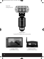
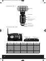
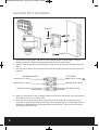
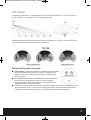
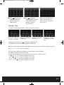
GuardCam WF Manual_Layout 2 28/11/2013 10:29 Page 1 Wire free external area protection system Installation and operation manual GuardCam WF-SAR • GuardCam WF-T • GuardCam WF-MR GuardCam WF Manual_Layout 2 28/11/2013 10:29 Page 2 2 GuardCam WF Manual_Layout 2 28/11/2013 10:29 Page 3 Table of contents System components . . . . . . . . . . . . . . . . . . . . . . . . . . . . . . . . . . . . . . . . . . . . . . . . . . . . 4 Introduction . . . . . . . . . . . . . . . . . . . . . . . . . . . . . . . . . . . . . . . . . . . . . . . . . . . . . . . . . . . . 5 GuardCam WF-T . . . . . . . . . . . . . . . . . . . . . . . . . . . . . . . . . . . . . . . . . . . . . . . . . . . . . . . . 6 GuardCam WF-SAR . . . . . . . . . . . . . . . . . . . . . . . . . . . . . . . . . . . . . . . . . . . . . . . . . . . . . 6 GuardCam WF-MR . . . . . . . . . . . . . . . . . . . . . . . . . . . . . . . . . . . . . . . . . . . . . . . . . . . . . . 7 GuardCam WF-T Installation . . . . . . . . . . . . . . . . . . . . . . . . . . . . . . . . . . . . . . . . . . . . . 8 PIR Set Up . . . . . . . . . . . . . . . . . . . . . . . . . . . . . . . . . . . . . . . . . . . . . . . . . . . . . . . . . . . . . 9 System Set Up . . . . . . . . . . . . . . . . . . . . . . . . . . . . . . . . . . . . . . . . . . . . . . . . . . . . . . . . 10 System Setup . . . . . . . . . . . . . . . . . . . . . . . . . . . . . . . . . . . . . . . . . . . . . . . . . . . . . . . . . 14 Captured Image Playback Software . . . . . . . . . . . . . . . . . . . . . . . . . . . . . . . . . . . . 17 Connecting to a Television . . . . . . . . . . . . . . . . . . . . . . . . . . . . . . . . . . . . . . . . . . . . . 21 Trouble Shooting Guide . . . . . . . . . . . . . . . . . . . . . . . . . . . . . . . . . . . . . . . . . . . . . . . . 22 Best Practice . . . . . . . . . . . . . . . . . . . . . . . . . . . . . . . . . . . . . . . . . . . . . . . . . . . . . . . . . 23 Technical Specifications . . . . . . . . . . . . . . . . . . . . . . . . . . . . . . . . . . . . . . . . . . . . . . . 24 3 GuardCam WF Manual_Layout 2 28/11/2013 10:29 Page 4 System components GuardCam WF-T Combined PIR Floodlight camera and transmitter 4 GuardCam WF-MR GuardCam WF-SAR Combined Monitor receiver Stand alone receiver module GuardCam WF Manual_Layout 2 28/11/2013 10:29 Page 5 Introduction The GuardCam-WF range of products are an ideal solution for the protection of external areas around domestic or light commercial properties. Images are captured by wire free cctv cameras built into pir controlled security lighting units and digitally transmitted to a choice of receivers with integral SD card recording. GuardCam operates on a secure stable 2.4ghz frequency to provide excellent range and image quality. The feature packed yet user friendly control interface provides a number of useful options. To obtain the most from your GuardCam-WF installation please read through this manual carefully. Getting the best from Wire free technology Whilst employing the benefits of latest digital signal technology a number of key factors should be remembered when siting both transmitter and receiver units. Think of the wire free signal travelling as a straight line between transmitter and receiver –“ The line of transmission”. The stated Open field range of 150M is exactly that , across an open field. Any line of transmission obstruction will reduce the useful range. When siting units consider minimising the number of walls, trees, doors, hills within landscaping or other solid objects that exist along the line of transmission. Avoid a line of transmission that follows the whole length of a wall rather than directly through it. A small adjustment to the position of either transmitter or receiver can make a huge difference to performance . Avoid siting transmitter or receiver units in close proximity to other wire free equipment such as routers, baby monitors or sources of electrical energy such as microwave ovens, very high voltage cable etc. Following these guidelines will achieve the best results from a given site. The construction method of obstructions will create variance in results however a satisfactory system should be achieveable on most buildings up to 4000 sq meters. System architecture Up to four transmitters (GuardCam WF-T) can be paired with a single receiver (either GuardCam WFMR or GuardCam WF-SAR). OR Note. A transmitter can only be paired with one receiver at a time. It is not possible to pair a single transmitter with two separate receivers. 5 GuardCam WF Manual_Layout 2 28/11/2013 10:29 Page 6 GuardCam WF-T LED light Pairing button Camera Termination box and mounting plate PIR detector Time adjustment / Lux adjustment GuardCam WF-SAR 1 10 2 3 6 8 9 4 5vDC power input 5 Reset AV out Jack Micro SD slot Power Button 7 1 2 3 4 5 6 7 8 9 10 6 DISPLAY MENU PLAYBACK Switch Channel Menu Switch Channel ESC REC/STOP ZOOM ALARM Cursor UP OK / ENTER Cursor Down EXIT Fast Forward PLAY / PAUSE Fast Backward Previous DEL Next REC MODE OTHER Link indicator Power indicator STOP Power Button GuardCam WF Manual_Layout 2 28/11/2013 10:29 Page 7 GuardCam WF-MR 12 1 2 4 Power Button Antenna 3 5 Micro SD slot 6 7 8 9 Reset 10 Speaker AV out Jack Speaker 11 Adaptor Plug Flip-out Stand 1 2 3 4 5 6 7 8 9 10 11 12 DISPLAY MENU PLAYBACK REC MODE Channel up Cursor UP menu Left OK / ENTER menu Right menu Down EXIT Fast Forward Switch Display CH PLAY / PAUSE Switch Display CH Fast Backward Previous Next Start/STOP Menu Channel down OTHER Link indicator Power indicator ZOOM Alarm on/off Power Button On screen Icons General Display mode Battery Power Indicator Channel Indicator Quad Display 100% Strength Signal Indicator Scan Display 70% Strength Recording Indicator (Red Flashing) Single Display 50% Strength 20% Strength 7 GuardCam WF Manual_Layout 2 28/11/2013 10:29 Page 8 GuardCam WF-T Installation Screw E Screw E Screw A 1. Place plastic masonry plugs into desired surface aligning holes as shown above. Using an electric screwdriver, fasten mounting plate directly to surface using screws E. 2. Feed the cable through the back mounting box and bush the cable entry to avoid abrasion to the cable. 3. Wire the unit as follows: (Ensure all wires are connected securely and that no loose strands are exposed) INCOMING SUPPLY EARTH (Green & Yellow) NEUTRAL (Blue or Black) LIVE (Brown or Red) TO FITTING EARTH (Green & Yellow) NEUTRAL (Blue or Black) LIVE (Brown or Red) 4. Make sure the polarity is correct. Double check the connections after wiring. Errors may damage the motion sensor or cause a fire hazard. 5. Attach the unit to the mounting plate. You will first need to angle the unit back so that the catch at the top of the mounting plate fits into slot on the back of the unit. Next lower the unit until holes at the bottom of the mounting plate and unit are flush. Then screw (screw A) into this hole, tightening carefully. 8 GuardCam WF Manual_Layout 2 28/11/2013 10:29 Page 9 PIR Set Up For optimum performance it is recommended to mount the GuardCam WF-T 1.8 to 2.5 m above the ground. The PIR has a range of 12m over a 140 degree angle. 140º 12m 2.5m PIR technology provides much better target capture if movement is across the face of the PIR. Aim the PIR to achieve the highest chance of this happening. Setting the Time and Lux control Time control: The time the floodlight is illuminated after triggering can be set between 30 seconds to 7 minutes. Turning the dial clockwise will increase the time, turning counter-clockwise will reduce the time. Lux control: PIR activation of the floodlight is also controlled by a photocell to ensure illumination only occurs when required. Adjustment can be set between darkness , fully clockwise and daylight (walktest), fully anti clockwise. To perform a walk test turn the dial fully anti clockwise. When the walk test is completed adjust the dial clockwise to the "+" side to your desired light on time (we recommend this be at least 2 minutes to ensure lighting of the area is sufficient for the minimum recording time. 9 GuardCam WF Manual_Layout 2 28/11/2013 10:29 Page 10 System Set Up Before commencing system configuration ensure all GuardCam WF –T units to be included in the system are powered and a clean formatted mini SD card is present in the chosen GuardCam WF receiver. Please also ensure the chosen GuardCam RF receiver is powered using the supplied 5VDC plug in power supply. Important. Only use the plug in power supply provided with the unit. Use of other power supplies may damage the unit and invalidate the warranty. Note. It is not possible to enter the set up menu if a recording session is occurring. It is possible to stop recording by pressing Rec/Del. Main Menu Press the MENU button to enter the MAIN MENU. The system highlights EVENT LIST by default. Use to navigate through the menus; press the MENU button to confirm selection and enter sub-menu. Camera Setup Select CAMERA SETUP, press the MENU button to enter sub-menu. Use to select the camera to set up (camera 1-4). Use to select the sub-menu Pair a new device (GuardCam WF-T) Pairing GuardCam WF-T to a Receiver Pairing allows the GuardCam WF-T to communicate with a chosen receiver (GuardCam WF-MR or GuardCam WF-SAR). Up to four GuardCam WF-T transmitters can be paired with each receiver. A GuardCam WF-T can only be paired to a single receiver at any one time. Pairing to a second receiver will delete the pairing with the initial receiver. The GuardCam WF-T pairing button is located to the rear of the floodlight. Pair each GuardCam WF-T individually to a separate channel. With the PAIRING option highlighted, press the menu / select button once to begin camera pairing. Press and release the pairing button on the GuardCam WF-T twice. The System will confirm pairing process to be successful by displaying "PAIRED" on screen. 10 GuardCam WF Manual_Layout 2 28/11/2013 10:29 Page 11 Image brightness adjustment Press ▼▲ to select a camera for adjustment. Press ▼▲ to select brightness level. Press ESC to return to MAIN MENU or press ▼▲ to select another camera. Camera Activation It is possible to turn cameras on or off. Please turn cameras to off position if channel has no camera paired. Press ▼▲ to select a camera for adjustment. Press ▼▲ camera on or off. Press ESC to return to MAIN MENU or press ▼▲ to select another camera. Record Setup From main menu select record setup icon, press the MENU button to enter sub-menu. Use ▼▲ to select the required sub menu. Record mode selection It is possible to select a specific recording style for each hour of the day or generally for the whole day. Note : all channels are effected by selection made M-Motion Only record when on movement is visible on screen S-Schedule Always record at all times X-Manual Select a record style for each time of day Use to select the recording style If X-Manual is selected use and ▼▲ to select each hour of the day then press menu to toggle through the record options ( Manual , Schedule, Motion ) for the selected hour. Note : A recording cannot be stopped until 30 seconds after the start of a recording by any method. To manually stop recording, press REC/DEL on the front panel. Menu control functions are disabled while system is recording. NB . A manual recording can be activated in any mode by pressing the Rec/Del button. 11 GuardCam WF Manual_Layout 2 28/11/2013 10:29 Page 12 Motion Detection Sensitivity Motion detection sensitivity can be selected on each camera from highest sensitivity to off. This can be useful when motion detection recording mode is selected for the whole system but only certain cameras are required to make a motion record trigger. Use ▼▲ to select motion detection sensitivity section Use to highlight camera for setup Use ▼▲ to adjust sensitivity level Press ESC to save and exit. Setup Masking Area Specific sections within the viewed area can be masked to avoid false or repetitive triggering by motion detection. Use ▼▲ to select SETUP MASKING AREA section. Use to highlight camera for setup, press MENU to enter. Usee to highlight the grid for motion detection area. Use the MENU button to mask/unmask within the grid. Movements taking place inside the masked area will be ignored. Use to select another grid for setup or press ESC to save and exit. Record Time The length of record time following a motion trigger can be selected between three options. 2 minutes, 5 minutes or 10 minutes. Use ▼▲ to select RECORD TIME section. Use to highlight recording period: 2 Min / 5 Min / 10 Min, press the MENU button to confirm. Press ESC to save and exit. Event List Playback Select EVENT LIST, press the main menu to enter sub-menu. Use to highlight desired DATE index for playback. Press MENU to confirm selection and enter selected folder. 12 GuardCam WF Manual_Layout 2 28/11/2013 10:29 Page 13 Press to select Hour (each block represents one hour time). Press MENU to enter. Use to highlight desired HOUR for playback. Press MENU to confirm selection and enter selected folder. NOTE: Each RECORDED FILE folder indicated with file start / end time and type of file recorded. Starting / Time The type of recorded file (Schedule / Motion / Manual) is indicated. Start Time = PM10:33 End Time = PM10:43 Channel 1 is SCHEDULE Channel 1 is MOTION recorded file recorded file Channel 1, 2, 3 and 4 are MANUAL recorded files To playback recorded file, use to highlight RECORDED FILE. Press MENU to confirm selection and playback selected file. NOTE: By default, playback display will be QUAD (displaying images of all cameras paired to receiver). ■ 1 2 3 4 = All channel playback For single camera display, press MENU once after playback started to PAUSE. Use ◄► to select from channel to channel. Channel indicator (bottom left screen) will indicate the channel number selected. □ 1 2 3 4 = Channel 1 playback in full screen □ 1 2 3 4 = Channel 2 playback in full screen □ 1 2 3 4 = Channel 3 playback in full screen □ 1 2 3 4 = Channel 4 playback in full screen 13 GuardCam WF Manual_Layout 2 28/11/2013 10:29 Page 14 System Setup Select to set up the general configuration of the system. Select SYSTEM SETUP, press the MENU button to enter sub-menu. Use ▼▲ to select the sub menu Date and Time Use ▲▼ to highlight DATE AND TIME, press MENU to enter. Use to highlight adjust: YEAR / MONTH / DATE / HOUR / MINUTE, use ▲▼ to adjust each section and press MENU to confirm adjustment. Press ESC to save and exit. TV Output Adjusts the TV output protocol between PAL and NTSC NB Ensure PAL is selected for use in the UK. Use to highlight NTSC or PAL, press MENU to confirm selection. Press ESC to save and exit. Power Saving After a preset time following no button or menu selection the system can automatically switch off the monitor (only when using GuardCam WF –MR) to save energy and preserve screen life. Use to select SCREEN OFF AFTER 5 MINUTES / SCREEN OFF AFTER 10 MINUTES IDLE / SCREEN ALWAYS ON, press MENU to confirm setting. Press ESC to save and exit. NOTE: POWER SAVING is for GuardCam WF-MR ONLY. 14 GuardCam WF Manual_Layout 2 28/11/2013 10:29 Page 15 Multi Channels Idle Display Selects style of display after no inputs received or selections made for 3 minutes . Use to select: DISPLAY QUAD(all images) after idle period Display each channel at 5 SEC intervals Display each channel at 10 SEC intervals Display each channel at 15 SEC intervals Press MENU to confirm selection Press ESC to save and exit Display QUAD mode Display each channel at 5 sec Intervals Display each channel at 10 sec Intervals Display each channel at 15 sec Intervals Default Use to select the system language for SYSTEM RESTORE. Press MENU to confirm selection and system will restore to factory default. A. Camera Setup CH1=ON CH2=ON CH3=OFF CH4=OFF Brightness= level 2 B. Recorder Setup X = Manual REC Motion detection sensitivity = level 2 Masking area = all activated REC time = 2 minutes C. System Setup Time = 2013 01 01 Power Save = OFF Idle display = Quad D. Alarm = OFF E. SD Card Overwrite = OFF 15 GuardCam WF Manual_Layout 2 28/11/2013 10:29 Page 16 Alarm Buzzer Select on/off for alarm sound on activation of motion detection on any camera . Select ALARM BUZZER, press the MENU button to turn buzzer ON or OFF. Note: The SD card must be inserted and have sufficient space for the alarm to operate. Alarm can also be switched on and off at front panel Pan, Tilt, Zoom Allows user to zoom image by 2x and then move around the zoomed image in the horizontal and vertical plane. Select PAN TILT ZOOM, press the MENU button to enter ZOOM mode, press MENU again to zoom in (2X). When zoomed in, use to select various view areas. Press MENU to zoom out. In zoom out (1X), use ▲▼ to change available channel. Press ESC to exit ZOOM. Scan Activated Cameras Used to check which cameras are paired to the system and switched on. Select SCAN ACTIVATED CAMERAS, press MENU once to begin camera scan mode. Note: System will automatically activate QUAD display if recording function is activated. Memory Card Overwrite When memory card overwrite is selected the system will record over the oldest recorded file when the SD card is full Select MEMORY CARD OVERWRITE, press MENU to activate overwrite function and press MENU again to deactivate. Note: One of the following examples will appear on MAIN MENU. (1) Available capacity on memory card. (2) ERROR - either memory card is missing, locked or damaged. If the overwrite function is not selected the system will display "MEMORY FULL PLEASE FORMAT" on preview screen when the SD card is full. Please be sure to backup the data if required to an alternative storage device before formatting the memory card. 16 GuardCam WF Manual_Layout 2 28/11/2013 10:29 Page 17 Captured Image Playback Software Images captured by GuardCam-WF can be transferred to PC for storage and transfer. To increase the security of these images they are encoded in .snx format. Playback and control of .snx files is possible via the Sec24 Media Player included on the CD provided with your GuardCam-WF. Files are physically transferred from GuardCam-WFs micro SD card using the included MicroSD – SD coverter and SD – USB adaptor. 1 2 3 4 5 6 7 8 1. Channel 1 Playback Screen 2. Channel 2 Playback Screen 3. Channel 3 Playback Screen 4. Channel 4 Playback Screen 9 10 11 5. Playback Progress Bar 6. Play 7. Pause 8. Stop 12 9. Fast Rewind 10. Fast Forward 11. Load Recorded File(s) 12. Channel Enable / Disable Select 17 GuardCam WF Manual_Layout 2 28/11/2013 10:29 Page 18 Software Installation Insert the CD into the CD-ROM of the PC. Click on MY COMPUTER, double click on the drive where the CD-ROM is assigned by the PC (for example: E;\) and you will find the Sec24 Media Player icon. Please read the following steps to complete installation. Sec24 Media Player icon If Window 7 is running on your PC, please right click on icon “Sec24 Media Player” and select “Run as administrator” option first to begin installation. Note: The following error message will appear if you did not select “Run as administrator” option first before starting the installation. 18 GuardCam WF Manual_Layout 2 28/11/2013 10:29 Page 19 Double click the icon to start the installation process. Click “Next” to continue the installation. When the installation is completed, click “Finish” to exit the install wizard. 19 GuardCam WF Manual_Layout 2 28/11/2013 10:29 Page 20 Playback Recorded File(s) Double click the Sec24 Media Player icon on the desktop to start the software.  Sec24 Media Player icon Click on “Load” to import and playback previous recorded files (SNX files) already stored on your PC. Note: You will first need to save the files from the Micro SD card to the PC first. Using the supplied SD-USB adapter. During playback, all four channels can playback at once. Select 1 to playback video image from channel 1 Select 2 to playback video image from channel 2 Select 3 to playback video image from channel 3 Select 4 to playback video image from channel 4 When more then one channel selected for playback, system will display playback screen in QUAD format. Please note that if you wish to distribute .SNX files the PC used for viewing must also load the enclosed sec24 media player software. 20 GuardCam WF Manual_Layout 2 28/11/2013 10:29 Page 21 Connecting to a Television Both GuardCam WF receivers can be directly connected to a television with AV inputs to display live images or menu controls. An AV lead is supplied for this purpose. GUARDCAM WF-MR GUARDCAM WF-SAR 21 GuardCam WF Manual_Layout 2 28/11/2013 10:29 Page 22 Trouble Shooting Guide 22 Problem Solution No image appears • Make sure the power adaptor is not damaged or defective and is plugged into an electrical outlet with power. • Make sure the receiver has enough charge • Make sure the GuardCam-WF-T is powered. • Relocate the camera/receiver to obtain the best reception for wireless signals. • Make sure the camera is properly paired to the receiver. • Make sure your paired transmitter is not located on another channel. • Press the Menu button on the receiver to exit the system idle mode and go back to the main screen. Low wireless signal or Low frame rate • Other wireless devices may reduce the signal strength. • Leave as much space as possible between the transmitter(s)/receiver and wireless devices. • Flip the antenna of the receiver to obtain the best reception from the GuardCam WF-T units. Poor picture quality • Move the GuardCam WF-T(s) and receiver closer to ensure the appropriate wireless range. • Remove the obstacles between the camera(s) and receiver. • Clean the camera lens using lens cleaning cloth. Spots or dust on the lens can also cause image quality issues. Motion detection not working • Confirm the motion detection has been correctly set up or scheduled. • Adjust the sensitivity of the motion sensor. The recording doesn’t work as scheduled. • Make sure correct DATE AND TIME has been correctly set. • Make sure the Record Schedule has been setup correctly. • Make sure the memory card is inserted and formatted. • In motion detection mode, a moving object within the camera viewing angle is necessary to trigger the motion sensor for recording. Unable to pair the camera to the receiver • Make sure the camera and the receiver are powered on. • Press and release the pairing button on the camera. • Power off the receiver and restart. If power button does not work, use a pin to press the reset button on the side of the receiver. Memory card error • Make sure the memory card is correctly inserted and formatted. Wrong data and/or time is shown. • Wrong date and/or time will result in unexpected record schedule. Please configure correct system date/time. Please note Time and date settings will be lost if the receiver looses power . More cameras are added but not all of them show images on the receiver • Make sure all cameras are properly paired. • Make sure all cameras are properly activated. • Follow the solution of ‘No image appears’. GuardCam WF Manual_Layout 2 28/11/2013 10:29 Page 23 Best Practice Please consider the following points to achieve best performance from your GuardCam WF system. Before inserting an SD card for the first time and each time it is re-inserted it’s a good idea to format the card using a PC or Laptop. To format the SD card Ensure to save any required images to an alternative folder prior to formatting. – Place it in the SD / USB adaptor supplied – Place the adaptor in a spare USB port on your PC / Laptop – Right click on the SD card location – Select Format – Ensure the correct file system is selected FAT16 ( or FAT ) for SD and FAT32 for SDHC – Ensure the Quick Format option is NOT selected – Select "Start" Following these simple points will ensure correct operation of GuardCam WF and should be considered as part of its maintenance schedule. Bear in mind that time and date settings should be checked on the GuardCam WF receivers if the units may have been left without power. If power has been removed from the receiver and / or battery power has been lost stored images will retain the correct time and date stamp however time and date settings will need to be corrected before starting further recording sessions. GuardCam WF-T transmitter units should not be mounted lower than 1.8m to achieve best detection range and avoid unwanted attention. Use the built in motion detection masking facility to avoid false triggering of recordings in areas where recording is not required. Regularly clean the camera and PIR lens of the GuardCam WF-T with a soft dry cloth. Avoid locating GuardCam WF receivers in close proximity to sources of electrical energy or wire free transmissions. Carefully consider the line of transmission between the location of transmitters and receivers. Try to avoid locations where the line will travel along the length of a wall or other solid object rather than directly through it. 23 GuardCam WF Manual_Layout 2 28/11/2013 10:29 Page 24 Technical Specifications GuardCam WF-T Detection Method Sensor Range Camera Resolution LED Floodlight output Lumen output Time adjustment Lux adjustment Transmitter signal technology Transmitter output power Transmission Range Voltage Current drain IP rating Operating Temperature Dimensions Weight Passive Infrared 12m x 140° 640 X 480 8 PCS 1W Nichia High Power LED 1100 30 seconds ~ 7 minutes Dark - daylight 2.4G FHSS Technology 16bBm 150m open field 100-240V 50Hz/60Hz 225±20mA IP55 -10°C ~ 40°C 160 x 176 x 260MM 1400g GuardCam WF-SAR Channels Reception Range Receiver Resolution Maximum SD card size Receiver technology Video Output Operating Voltage Current Consumption Operating Temperature Dimensions Weight 4 150 meters in open field 800 X 480 32Gb 2.4GHz FHSS Technology 1.2±0.2Vp-p/75ohm DC 5V / 1A 250mA(max) -10°C ~ 50°C 122 x 113 x 25 mm 335g GuardCam WF-MR Channels Reception Range Receiver Resolution Screen size Maximum SD card size Receiver technology Video Output Operating Voltage Current Consumption Operating Temperature Video Output Audio output Dimension Weight Elite Security Products Unit 7, Target Park, Shawbank Rd Lakeside, Redditch B98 8YN 4 150 meters in open field 800 X 480 7” Screen (16:9) 32Gb 2.4GHz FHSS Technology 1.2±0.2Vp-p/75ohm DC 5V / 1A 860mA(max) -10°C ~ 50°C 1.2±0.2Vp-p/75ohm 75±10dB 200 x 122 x 26 mm 400g Telephone: 01527 515150 Fax: 01527 515143 email: [email protected]