1
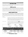
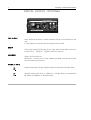
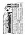
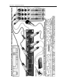
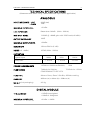
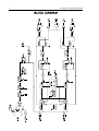
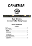
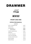
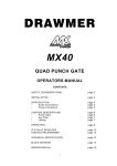
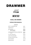
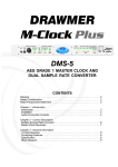
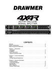
DRAWMER
Stereo Vacuum Tube
Compressor
with Instrument & Mic Pre
OPERATORS MANUAL
CONTENTS
SAFETY CONSIDERATIONS
INTRODUCTION
INSTALLATION
•
Audio Connections
•
Power Connection
•
Digital Module
CONTROL DESCRIPTIONS
•
Analogue
•
Digital
OPERATION
IF A FAULT DEVELOPS
CONTACTING DRAWMER
TECHNICAL SPECIFICATION
BLOCK DIAGRAM
i
page 1
page 2
page 2
page 3
page 4
page
page
page
page
page
page
page
5
8
9
12
12
13
14
COPYRIGHT
This manual is copyrighted © 2002 by Drawmer Electronics, Ltd. With all rights
reserved. Under copyright laws, this manual may not be duplicated in whole or in
part without the written consent of Drawmer.
ONE YEAR LIMITED WARRANTY
Drawmer Electronics Ltd., warrants the Drawmer Tube Station 1 audio processor to
conform substantially to the specifications of this manual for a period of one year
from the original date of purchase when used in accordance with the specifications
detailed in this manual. In the case of a valid warranty claim, your sole and exclusive
remedy and Drawmer’s entire liability under any theory of liability will be to, at
Drawmer’s discretion, repair or replace the product without charge, or, if not
possible, to refund the purchase price to you. This warranty is not transferable. It
applies only to the original purchaser of the product.
For warranty service please call your local Drawmer dealer. Alternatively call
Drawmer Electronics Ltd. at +44 (0)1709 527574. Then ship the defective product,
with transportation and insurance charges pre-paid, to Drawmer Electronics Ltd.,
Coleman Street, Parkgate, Rotherham, S62 6EL UK. Write the RA number in large
letters in a prominent position on the shipping box. Enclose your name, address,
telephone number, copy of the original sales invoice and a detailed description of
the problem. Drawmer will not accept responsibility for loss or damage during
transit.
This warranty is void if the product has been damaged by misuse, modification or
unauthorised repair.
THIS WARRANTY IS IN LIEU OF ALL WARRANTIES, WHETHER ORAL OR WRITTEN,
EXPRESSED, IMPLIED OR STATUTORY. DRAWMER MAKES NO OTHER WARRANTY
EITHER EXPRESS OR IMPLIED, INCLUDING, WITHOUT LIMITATION, ANY IMPLIED
WARRANTIES OF MERCHANTABILITY, FITNESS FOR A PARTICULAR PURPOSE, OR
NON-INFRINGEMENT. PURCHASER’S SOLE AND EXCLUSIVE REMEDY UNDER THIS
WARRANTY SHALL BE REPAIR OR REPLACEMENT AS SPECIFIED HEREIN.
IN NO EVENT WILL DRAWMER ELECTRONICS LTD. BE LIABLE FOR ANY DIRECT,
INDIRECT, SPECIAL, INCIDENTAL OR CONSEQUENTIAL DAMAGES RESULTING
FROM ANY DEFECT IN THE PRODUCT, INCLUDING LOST PROFITS, DAMAGE TO
PROPERTY, AND, TO THE EXTENT PERMITTED BY LAW, DAMAGE FOR PERSONAL
INJURY, EVEN IF DRAWMER HAS BEEN ADVISED OF THE POSSIBILITY OF SUCH
DAMAGES.
Some states and specific countries do not allow the exclusion of implied warranties
or limitations on how long an implied warranty may last, so the above limitations
may not apply to you. This warranty gives you specific legal rights. You may have
additional rights that vary from state to state, and country to country.
In the interests of product development, Drawmer reserve the right to modify or
improve specifications of this product at any time, without prior notice.
ii
1
Tube Station 1 OPERATORS’ MANUAL
DRAWMER Tube Station 1
Stereo Vacuum Tube
Compressor with Instrument
& Mic Pre
SAFETY CONSIDERATIONS
CAUTION - MAINS FUSE
TO REDUCE THE RISK OF FIRE REPLACE THE MAINS FUSE ONLY WITH THE
SAME TYPE, WHICH MUST BE A CLASS 3, 250 VOLT, TIME DELAY TYPE,
RATED AT 160mA WHERE THE MAINS INPUT IS SET TO 230 VOLTS AC. AND
315mA WHERE THE MAINS INPUT VOLTAGE IS 115 VOLTS AC.
ALL FUSES MUST COMPLY WITH IEC127-2.
THE FUSE BODY SIZE IS 20mm x 5mm.
CAUTION - MAINS CABLE
DO NOT ATTEMPT TO CHANGE OR TAMPER WITH THE SUPPLIED MAINS
CABLE.
CAUTION - SERVICING
DO NOT PERFORM ANY SERVICING. REFER ALL SERVICING TO QUALIFIED
SERVICE PERSONNEL.
WARNING
TO REDUCE THE RISK OF FIRE OR ELECTRIC SHOCK DO NOT EXPOSE THIS
EQUIPMENT TO RAIN OR MOISTURE.
2
Tube Station 1 OPERATORS’ MANUAL
INTRODUCTION
The Tube Station 1 is a high quality Stereo Vacuum Tube Compressor with Instrument
& Mic Pre. It has an optional Digital Output module which enables SPDIF and AES/EBU
to be output from the unit. The Tube Station 1 is suitable for both live sound and studio
applications. All buttons have status LEDs.
INSTALLATION
The TS1 is designed for standard 19" rack mounting and occupies 1U of rack space.
Because the tube circuitry generates more heat than an equivalent solid-state design,
it is recommended that 1u of space is left above and below the unit, where space is
available, to allow the heat to dissipate. In addition the rack should be fan cooled, with
air blowing onto the TS1, this will extend the life and reliability of the units. Avoid
mounting the unit directly above power amplifiers or power supplies that radiate
significant amounts of heat and always connect the mains earth to the unit.
AUDIO CONNECTIONS
Input and Output connections are provided for use at +4dBu via balanced XLRs for
Mic. Line is at +4dBu via a Balanced jack, if unbalanced operation at +4dBu is
required, simply connect the unused terminal to Ground inside the balanced jack
socket. This applies to both inputs and outputs. The wiring convention for XLR being:
pin 1 Ground, pin 2 Hot and pin 3 Cold. For use with unbalanced systems, the Cold pin
3 must be grounded at both the input and output XLR’s. For jack operation refer to
diagram.
Interference:
If the unit is to be used where it maybe exposed to high levels of
disturbance such as found close to a TV or radio transmitter, we
suggest that the unit be operated using the XLR connectors. The
screens of the signal cables should be connected to the chassis
connection on the XLR connector as opposed to connecting to
pin1. The TS1 fully conforms to the EMC standards.
Ground Loops:
If ground loop problems are encountered, never disconnect the
mains earth, but try disconnecting the signal screen on one end
of each of the cables connecting the outputs of the TS1 to the
patchbay. If such measures are necessary, balanced operation is
recommended.
AUDIO CONNECTION DIAGRAM
3
Tube Station 1 OPERATORS’ MANUAL
POWER CONNECTION
If the unit is required to operate at a mains input voltage which is different to that
supplied:
The following procedure must be carried out by a qualified technical engineer.
1:
Disconnect the unit from the mains.
2:
Remove the twelve screws that retain the top cover.
Accessing the internal power switch and fuse
3. Set the voltage rating and replace the fuse.
Mains Voltage
230V
Fuse Value
Mains Voltage
115V
Fuse Value
4. Replace the cover.
160mA.
315mA.
4
Tube Station 1 OPERATORS’ MANUAL
DIGITAL MODULE INSTALLATION
The Digital modules are designed only for operation within a Drawmer Tube Station.
Under NO circumstances should the module be installed into any other manufacturers’
or custom device.
Full anti static handling precautions must be followed to prevent
damage to sensitive circuitry.
To Install the module:
a:
Disconnect the mains power cable from the unit.
b:
Remove the top cover.
c:
Remove the blanking panel from the rear of the unit.
d:
Slide the Digital Module through the rear panel.
e:
Fasten the Digital Cover Plate to the rear panel.
f:
Fasten the Digital PCB onto the three supporting posts.
g:
Connect the flexi strip into the holder on the main board.
h:
Replace the top cover.
Tube Station 1 OPERATORS’ MANUAL
5
CONTROL DESCRIPTION
INPUT and FRONT END SECTION
Pre-Amp Input
Selects the Instrument input
................................................................................
Gain
48V
Adjusts the Mic Gain over a range of 0dB to 60dB.
Adjusts the instrument gain over a range of !20dB to +40dB.
Switches on the phantom power if Mic source is selected.
2Rev
Inverts the phase of the signal leaving the preamplifier.
................................................................................
Hi Pass.
H.F. Contour
25Hz - 250Hz
The Hi Pass filter severely attenuates frequencies below the
cut-off frequency selected.
Offers high frequency enhancement to add definition, particularly
to the human voice and acoustic instruments.
6
Tube Station 1 OPERATORS’ MANUAL
COMPRESSOR SECTION
Source
Compressor
Attack
Release
Selects between the Line Input and the Front End Section.
This serves as the input gain control to the compressor which has
a preset threshold. Rotate clockwise until the required amount of
compression is achieved. The amount of compression is indicated
by a LED bar indicator on the front panel.
Attack controls the speed at which the compressor responds to a
rise in signal level. The sound of any percussive signals can be
altered by using this control because long attack times allow the
initial part of the signal to escape compression thus giving a
certain amount of ‘punch’ to the sound.
Release controls the speed which the compressor recovers when
the signal drops in level. The faster the release, the louder the
apparent output level, but most compressors create some
distortion when short release times are used, so care should be
taken to arrive at the correct setting.
Tube Station 1 OPERATORS’ MANUAL
7
TUBE DRIVE
Tube Drive
Active
A variable control that regulates the amount of tube colouration.
Note: even with the control rotated fully counter-clockwise some
tube warmth will be added. To disable the tube stage fully, the
section must be switched off.
Switches the tube circuitry into the signal path and illuminates the
status LED.
OUTPUT SECTION
Gain Trim
Limit
Meters
Analogue Output
Bypass
The output level may be adjusted between !30dB and +5dB to
compensate for level changes caused by compression and
limiting.
This is a Hard level limiter fixed at +16dB (ref +4dBu). A led
indicates when limiting occurs.
Two eight-section LED meters display the signal level (from !35dB
to 0dB) sent to the Digital Output (if fitted).
Sets the overall Analogue output level of the TS1 from Off to
+16dB. Adjusting this control does not change the meter levels.
Switches the unit into Bypass to allow comparison with the input
signal, illuminates the status LED.
8
Tube Station 1 OPERATORS’ MANUAL
DIGITAL OUTPUT - OPTIONAL
EXT CLOCK
SPDIF
AES/EBU
Auto detects whether a valid external clock is connected to the
unit.
A Led lights to indicate that the signal has locked.
Via a high quality RCA type phono jack where the data conforms
to the Sony™ Phillips™ Digital InterFace format.
Via an XLR connector.
Wired pin 1 screen, pin 2 and 3 balanced data, and the XLR shell
connected to the chassis.
SAMPLE RATE
Selects between Single Sample Rate and Double Sample Rate.
Selects either 44.1KHz or 48KHz on Single Rate and between
88.2KHz and 96KHz on Double Rate.
Tube Station 1 OPERATORS’ MANUAL
9
10
Tube Station 1 OPERATORS’ MANUAL
Tube Station 1 OPERATORS’ MANUAL
11
12
Tube Station 1 OPERATORS’ MANUAL
IF A FAULT DEVELOPS
For warranty service please call Drawmer Electronics Ltd. Or their nearest authorised
service facility, giving full details of the difficulty. On receipt of this information,
service or shipping instructions will be forwarded to you. No equipment should be
returned under the warranty without prior consent from Drawmer or their authorised
representative.
For service claims under the warranty agreement a service Returns Authorisation (RA)
number will be given. Write this RA number in large letters in a prominent position on
the shipping box. Enclose your name, address, telephone number, copy of the original
sales invoice and a detailed description of the problem.
Authorised returns should be prepaid and must be insured. All Drawmer products are
packaged in specially designed containers for protection. If the unit is to be returned,
the original container must be used. If this container is not available, then the
equipment should be packaged in substantial shock-proof material, capable of
withstanding the handling for the transit.
CONTACTING DRAWMER
Drawmer Electronics Ltd., will be pleased to answer all application questions to
enhance your usage of this equipment. Please address correspondence to:
Drawmer (Technical Help line) : Coleman St. : Parkgate : Rotherham : S62 6EL : UK
or, E-mail us on :
[email protected]
Drawmer dealers, Authorised service departments and other contact information can
be obtained from our web pages on
http://www.drawmer.com
13
Tube Station 1 OPERATORS’ MANUAL
TECHNICAL SPECIFICATIONS
(Measurements taken using +4dBu balanced input where applicable)
ANALOGUE
INPUT IMPEDANCE - LINE
- INSTR
20KS (bal)
1MS
MAXIMUM INPUT LEVEL
+21dBu
LINE INPUT CMR
Better than !40dB
MIC INPUT NOISE
!130dB @ +60dB gain with 150S load (ref 0dBu)
OUTPUT IMPEDANCE
100S
MAXIMUM OUTPUT LEVEL
+20dBu
BANDWIDTH
12Hz to 52KHz (!1dB)
NOISE (ref +4dBu)
!87dB (22Hz - 22KHz)
(20Hz - 22KHz)
DISTORTION
Typical Input
Unity Gain
100Hz
1KHz
10KHz
< 0.03%
< 0.03%
<0.03%
POWER REQUIREMENTS
115Volt or 230Volt at 50-60Hz,
FUSE RATING
T160mA for 230Volt,
CONFORMING TO IEC127-2
FUSE TYPE
20mm x 5mm, Class 3 Slo-Blo, 250Volt working
CASE SIZE
482mm (w) x 44mm (h) x 228mm (d)
WEIGHT (incl packaging)
4.3 Kg
DIGITAL MODULE
THD and NOISE
>105dB Unweighted
>108dB A- Weighted
MAXIMUM INPUT LEVEL
+21dBu = 0dBfs
15VA
T315mA for 115Volt
14
Tube Station 1 OPERATORS’ MANUAL
BLOCK DIAGRAM