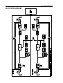
1
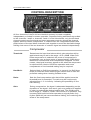
DL441
QUAD COMPRESSOR LIMITER
OPERATORS MANUAL
CONTENTS
SAFETY CONSIDERATIONS
page 1
INTRODUCTION
page 2
INSTALLATION
page 3
CONTROL DESCRIPTIONS
C
Compressor
C
Peak Limit
C
Stereo Link
page
page
page
page
OPERATION
page 7
IF A FAULT DEVELOPS
page 8
CONTACTING DRAWMER
page 8
TECHNICAL SPECIFICATION
page 9
BLOCK DIAGRAM
page 10
i
5
5
6
6
COPYRIGHT
This manual is copyrighted © 1997 by Drawmer Electronics, Ltd. With all rights
reserved. Under copyright laws, this manual may not be duplicated in whole or in
part without the written consent of Drawmer.
ONE YEAR LIMITED WARRANTY
Drawmer Electronics Ltd., warrants the Drawmer DL441 audio processor to
conform substantially to the specifications of this manual for a period of one year
from the original date of purchase when used in accordance with the
specifications detailed in this manual. In the case of a valid warranty claim, your
sole and exclusive remedy and Drawmer’s entire liability under any theory of
liability will be to, at Drawmer’s discretion, repair or replace the product without
charge, or, if not possible, to refund the purchase price to you. This warranty is
not transferable. It applies only to the original purchaser of the product.
For warranty service please call your local Drawmer dealer. Alternatively call
Drawmer Electronics Ltd. at +44 (0)1709 527574. Then ship the defective
product, with transportation and insurance charges pre-paid, to Drawmer
Electronics Ltd., Coleman Street, Parkgate, Rotherham, S62 6EL UK. Write the
RA number in large letters in a prominent position on the shipping box. Enclose
your name, address, telephone number, copy of the original sales invoice and a
detailed description of the problem. Drawmer will not accept responsibility for loss
or damage during transit.
This warranty is void if the product has been damaged by misuse, modification or
unauthorised repair.
THIS WARRANTY IS IN LIEU OF ALL WARRANTIES, WHETHER ORAL OR
WRITTEN, EXPRESSED, IMPLIED OR STATUTORY. DRAWMER MAKES NO
OTHER WARRANTY EITHER EXPRESS OR IMPLIED, INCLUDING, WITHOUT
LIMITATION, ANY IMPLIED WARRANTIES OF MERCHANTABILITY, FITNESS
FOR A PARTICULAR PURPOSE, OR NON-INFRINGEMENT. PURCHASER’S
SOLE AND EXCLUSIVE REMEDY UNDER THIS WARRANTY SHALL BE REPAIR
OR REPLACEMENT AS SPECIFIED HEREIN.
IN NO EVENT WILL DRAW MER ELECTRONICS LTD. BE LIABLE FOR ANY
DIRECT, INDIRECT, SPECIAL, INCIDENTAL OR CONSEQUENTIAL DAMAGES
RESULTING FROM ANY DEFECT IN THE PRODUCT, INCLUDING LOST
PROFITS, DAMAGE TO PROPERTY, AND, TO THE EXTENT PERMITTED BY
LAW, DAMAGE FOR PERSONAL INJURY, EVEN IF DRAWMER HAS BEEN
ADVISED OF THE POSSIBILITY OF SUCH DAMAGES.
Some states and specific countries do not allow the exclusion of implied
warranties or limitations on how long an implied warranty may last, so the above
limitations may not apply to you. This warranty gives you specific legal rights. You
may have additional rights that vary from state to state, and country to country.
In the interests of product development, Drawmer reserve the right to modify or
improve specifications of this product at any time, without prior notice.
ii
DL441 OPERATORS’ MANUAL
1
DRAWMER DL441
Quad Compressor Limiter
SAFETY CONSIDERATIONS
CAUTION - MAINS FUSE
TO REDUCE THE RISK OF FIRE REPLACE THE MAINS FUSE ONLY WITH
THE SAME TYPE, WHICH MUST BE A CLASS 3, 230 VOLT, TIME DELAY
TYPE, RATED AT 63mA WHERE THE MAINS INPUT VOLTAGE SWITCH IS
SET TO 230 VOLTS AC. AND 125mA WHERE THE MAINS INPUT VOLTAGE
IS 115 VOLTS AC.
ALL FUSES MUST COMPLY WITH IEC 127-2.
THE FUSE BODY SIZE IS 20mm x 5mm.
CAUTION - MAINS CABLE
DO NOT ATTEMPT TO CHANGE OR TAMPER WITH THE SUPPLIED MAINS
CABLE.
CAUTION - SERVICING
DO NOT PERFORM ANY SERVICING. REFER ALL SERVICING TO
QUALIFIED SERVICE PERSONNEL.
WARNING
TO REDUCE THE RISK OF FIRE OR ELECTRIC SHOCK DO NOT EXPOSE
THIS EQUIPMENT TO RAIN OR MOISTURE.
2
DL441 OPERATORS’ MANUAL
INTRODUCTION
The DL441 is a quad channel compressor / limiter designed to meet the needs of
professional studio and live sound applications. It may be used in balanced or
unbalanced systems and each channel is independently switchable between +4dBu
and -10dBv operating levels by means of a rear panel button. In addition to the
compressor / limiter, each channel also contains an independent, fast-acting peak
limiter.
The compressor section features a highly developed, auto attack/release system
which adapts itself to the programme material being processed and is equally
effective on individual sounds or complex mixes.
To maximise flexibility, each channel of the DL441 is switchable between traditional
ratio (hard knee) and soft-knee operation; in the soft-knee mode, the transition from
unity gain to gain reduction at the selected ratio is progressive and occurs over a
nominal 15dB input level range. The four channels may be operated independently or
linked in pairs for true stereo operation.
Traditionally, soft-knee compressors are preferable for unobtrusive level control or
for the control of finished mixes, whereas ratio type compressors are generally
considered more successful in creative applications or where large amounts of gain
reduction are required. By offering a choice of both modes, the DL441 is capable of
outstanding results in a very wide range of studio and live sound situations.
Also included in each channel of the DL441 is a peak limiter which allows the user to
set an absolute output signal level that will not be exceeded. If the peak limiter
threshold is exceeded for more than a few milliseconds, additional gain reduction will
be applied to reduce the overall signal level to within accepted limits without
distortion. Once the peak has passed, the system gain will return to normal after a
period of about one second. This facility is extremely valuable both in live sound
applications, for driver protection, and in digital recording where an absolute
maximum recording level exists. Furthermore, when deliberately overdriven, it can be
used creatively to produce level "pumping" effects which can be useful on electric
guitar or rock vocal sounds.
DL441 OPERATORS’ MANUAL
3
INSTALLATION
The DL441 is designed for standard 19" rack mounting and occupies 1U of rack
space. Avoid mounting the unit directly above power amplifiers or power supplies
that radiate significant amounts of heat and always connect the mains earth to the
unit. Fibre or plastic washers may be used to prevent the front panel becoming
marked by the mounting bolts.
AUDIO CONNECTIONS
INPUTS and OUTPUTS:
Both the input and output XLRs may be used either balanced or
unbalanced, the wiring convention being: pin 1 Ground, pin 2 Hot
and pin 3 Cold. The rear panel push buttons should be released
(out) for +4dBu operation or depressed (in) for -10dBV operation
in order to optimise the internal gain structure of the unit. For
use with unbalanced systems, the Cold pin (3) must be grounded
at both input and output XLRs.
Interference:
If the unit is to be used where it maybe exposed to high levels of
disturbance such as found close to a TV or radio transmitter, we
advise that the unit is operated in a balanced configuration. The
screens of the signal cables should be connected to the chassis
connection on the XLR connector as opposed to connecting to
pin1. The DL441 conforms to the EMC standards.
Ground Loops:
If ground loop problems are encountered, never disconnect the
mains earth, but instead, try disconnecting the signal screen on
one end of each of the cables connecting the outputs of the
DL441 to the patchbay. If such measures are necessary,
balanced operation is recommended.
POWER CONNECTION
The DL441 is supplied with a power cable suitable for domestic power outlets in your
country. For your own safety it is important that you use this cable to connect to the
mains supply earth. The cable should not be tampered with or modified.
If, for some reason, the unit is to be used at a mains input operating voltage which is
different to that as supplied, the following procedure must be carried out. (see
following diagram, over page)
4
DL441 OPERATORS’ MANUAL
1:
Disconnect the unit from the mains.
2:
Using a number 1 size pozidrive screwdriver, remove the two
self-tapping screws holding the voltage selection switch cover plate on
the rear panel.
3:
Remove the cover plate and slide the switch fully to its opposite end.
4:
Rotate the cover plate one half turn, (180E) and refit the two screws.
5:
Replace with a correctly rated fuse for the selected operation voltage.
6:
Re-connect to mains power source.
DL441 OPERATORS’ MANUAL
5
CONTROL DESCRIPTION
All four channels of the DL441 are identical and may be used completely
independently or linked for stereo operation. Separate linking switches are provided
to link channels 1 and 2 or channels 3 and 4. In the linked mode, only the left hand
channel controls are functional and serve as master controls, though the channel
bypass switches remain independent. In linked mode, the compressor/limiters and
peak limiters of the two linked channels track together to avoid the inevitable image
shifting that occurs if the two channels of a stereo signal are treated independently.
Compressor
Threshold:
Determines the input level above which gain reduction will be
applied and may be set in the range -40 to +20dB. When Soft
Knee compression is selected, the onset of compression is
progressive over an input range of approximately 15dB, above
which level conventional ratio compression is applied. For this
reason, the signal level may appear to fall when the compressor
is switched from Hard to Soft Knee operation and some
readjustment of the threshold setting may be required.
Hard/Soft:
Selects Hard or Soft Knee operation. In general, the Soft Knee
mode provides the least obtrusive gain control and is often the
preferred setting when treating finished mixes.
Ratio:
Sets the final compression ratio that will be applied once the
threshold level is exceeded. The ratio may be continuously
adjusted from 1.2:1 to infinity:1 allowing the possibility of true
hard limiting.
Gain:
During compression, the signal is attenuated depending on the
dynamics of the signal. As a result, gain may need to be applied
in order to produce the desired output level. The GAIN control
has a range of !20dB to +20dB. If the limiter is in operation, only
increase GAIN until the limiter operates on signal peaks. Any
further GAIN will just cause excessive limiting, thus reducing the
effect of the compressor.
6
DL441 OPERATORS’ MANUAL
Bypass:
This switch will disable the functioning of the Compressor
section and the Peak Limiter. If operating in Stereo Linked
mode, both linked channels will be bypassed simultaneously.
The DL441 Bypass is a 'hard bypass' which directly links the
input sockets to the output sockets whenever Bypass is active.
The adjacent red LED indicates the Bypass status.
Gain Reduction Meter:
An eight segment LED bargraph meter continuously monitors the
gain reduction applied by the compressor/limiter over the range
0 to 30dB.
Output Level Meter:
This is a 5-segment LED bargraph level meter that monitors the
level of the output signal over the range -10dB to +10dB with
reference to the selected (-10dBu or +4dBu) operating level.
Peak Limiter
Level:
This control sets an absolute limit to the level that the output
signal will not be permitted to exceed. This limiter is very fast
acting enabling it to control any peaks without audible distortion.
If the output signal is so high as to cause the limiter to operate
for more than 20mS, the system gain is automatically reduced to
bring the signal back within range. The system gain is then
returned to normal over a period of approximately one second.
The compressor Gain control should be used to ensure that the
peak limiter operates only rarely if at all if the limiter is to be
used purely for peak protection. Alternatively, the unit may be
deliberately driven into limiting to produce creative effects.
Linking
Stereo Link:
These two switches configure channels 1,2 or 3,4 for stereo
operation where the left hand channel’s controls act as masters
for both slave audio channels.
The same degree of gain reduction is applied to both audio
channels to prevent image shifting which would otherwise occur
whenever the left and right signal dynamics varied from each
other by any significant degree.
DL441 OPERATORS’ MANUAL
7
OPERATION
The unit should be connected in-line with the signal to be processed via suitable
insert points. Ensure that the insert send and return level on your console matches
the operating level set up using the rear panel push-buttons on the DL441. If not,
select the appropriate operating level on the DL441.
For mono use, each channel may be considered as being completely independent
and set up accordingly. For use with stereo signals such as complete mixes or
submixes, the appropriate pair of channels should be switched to Stereo Link mode
and all setting up done using the left hand channel(s) controls.
Setting up is simplified by the auto attack and release system which continually
optimises the attack and release times to suit the dynamics of the material being
processed. The ratio setting depends on how firmly the signal dynamics need
controlling; as a rule, higher ratios provide a higher degree of control but also tend to
be more audibly apparent in operation when high levels of gain reduction are
required. In general, a higher compression ratio may be used when in Soft Knee
mode without compromising the subjective sound quality.
Having selected Hard or Soft Knee and set a suitable Ratio, setting up is simply a
matter of adjusting the Threshold control until the desired amount of gain reduction
occurs. This is judged partly by ear and partly by observing the gain reduction meter.
Normally a maximum gain reduction of between 8dB and 12dB will be adequate. If
more gain reduction appears necessary, it is worth considering applying a
conservative degree of compression during recording and then further compression
while mixing.
Compressing during a mix does increase the subjective level of tape and other
background noises during pauses and quiet passages as maximum gain is applied
when the signal level is minimum. For this reason, it is unwise to use more
compression than is strictly necessary.
Finally, the Gain control may be set to provide the required output level using the
level meter as a guide. Avoid running at very high output levels as this reduces the
available amount of signal headroom and could lead to distortion in extreme cases.
Once the gain is correct, the Peak limiter Level control should be adjusted so that the
limiter LED only lights briefly on extreme signal peaks. Alternatively, the Peak limiter
Level may first be set to the desired value and then the compressor Gain control
adjusted to ensure minimum limiter activity.
The Peak limiter has no bypass control, but turning the Level control fully clockwise
will effectively prevent the limiter from operating.
Compressors are often accused of dulling the sound being processed, but the auto
circuitry in the DL441 has been designed to allow transient sounds to pass through
cleanly, thus maintaining the clarity and transparency of the original source. Soft
Knee operation is usually preferable when unobtrusive gain control is required.
8
DL441 OPERATORS’ MANUAL
IF A FAULT DEVELOPS
For warranty service please call Drawmer Electronics Ltd. Or their nearest
authorised service facility, giving full details of the difficulty. On receipt of this
information, service or shipping instructions will be forwarded to you. No equipment
should be returned under the warranty without prior consent from Drawmer or their
authorised representative.
For service claims under the warranty agreement a service Returns Authorisation
(RA) number will be given. Write this RA number in large letters in a prominent
position on the shipping box. Enclose your name, address, telephone number, copy
of the original sales invoice and a detailed description of the problem.
Authorised returns should be prepaid and must be insured. All Drawmer products are
packaged in specially designed containers for protection. If the unit is to be returned,
the original container must be used. If this container is not available, then the
equipment should be packaged in substantial shock-proof material, capable of
withstanding the handling for the transit.
CONTACTING DRAWMER
Drawmer Electronics Ltd., will be pleased to answer all application questions to
enhance your usage of this equipment. Please address correspondence to:
Drawmer (Technical Help line) : Coleman St.: Parkgate : Rotherham : S62 6EL : UK
or, E-mail us on :
[email protected]
Drawmer dealers, Authorised service departments and other contact information can
be obtained from our web pages on
http://www.drawmer.com
DL441 OPERATORS’ MANUAL
9
TECHNICAL SPECIFICATIONS
INPUT IMPEDANCE
20KOhm
MAXIMUM INPUT LEVEL
+21dBu (+17dB ref. +4dBu)
OUTPUT IMPEDANCE
50 Ohm
MAXIMUM OUTPUT LEVEL
+20dBu
BANDWIDTH
<12Hz to 35KHz -1dB
CROSSTALK
@10kHz
@20kHz
Better than !80dB
Better than !75dB
OUTPUT BALANCE
Better than 40dB 20Hz to 10kHz
INPUT CMR
Better than 40dB 20Hz to 10kHz
NOISE AT UNITY GAIN reference +4dBu
Wideband
22Hz - 22KHz
CCIR ARM
IEC A
Q-Pk CCIR
AV
!90dB
!98dB
!99dB
!100dB
!88dB
RMS
!89dB
!96dB
!97dB
!98dB
DISTORTION
100Hz
1KHz
10KHz
Unity Gain, +4dBu Input
< 0.02%
< 0.015%
< 0.035%
+14dBu Input, 10dB G.R.
< 0.3%
< 0.1%
< 0.1%
POWER REQUIREMENTS
115Volt or 230Volt at 50-60Hz,
13 W atts
FUSE RATING
63mA for 230Volt,
CONFORMING TO IEC 127-2
FUSE TYPE
20mm x 5mm, Class 3 Slo-Blo, 250Volt working
CASE SIZE
482mm (w) x 44mm (h) x 200mm (d)
WEIGHT (incl packaging)
3.4 Kgs
125mA for 115Volt
10
BLOCK DIAGRAM
DL441 OPERATORS’ MANUAL